Article

Investigation on a Shutdown Control Strategy with Residual Oxygen Rapid Elimination for Proton Exchange Membrane Fuel Cell System

1
Wuhan Institute of Marine Electric Propulsion, Wuhan 430070, China
2
School of Automotive Studies, Tongji University, Shanghai 201804, China
3
Institute of Carbon Neutrality, Tongji University, Shanghai 200092, China
*
Author to whom correspondence should be addressed.
Energies 2023, 16(3), 1285; https://doi.org/10.3390/en16031285
Submission received: 15 December 2022 / Revised: 9 January 2023 / Accepted: 20 January 2023 / Published: 25 January 2023
(This article belongs to the Section A5: Hydrogen Energy)

Abstract

:
During the shutdown process of the fuel cell system for vehicles, the air entering the anode chamber can form the hydrogen/air interface, accelerating the carbon corrosion of the catalytic layer. According to optimized control strategies, the carbon corrosion of fuel cells can be reduced. Nowadays, the main control strategies include gas purging and the consumption of residual oxygen in the stack by the auxiliary load. However, the oxygen in the fuel cell stack cannot be fully consumed or can cause the single-cell voltage to rise to 0.8 V with an inappropriate discharge current drop rate and auxiliary load resistance value, thus affecting the protective effect of the shutdown strategy. In this work, a shutdown strategy of the fuel cell system is studied. After the experiment, the optimized value of the discharge current drop rate and the auxiliary load resistance were obtained. With the resistance value of 50 Ω and the current drop rate of 7 A/s, the shutdown time of the fuel cell system is 13.5 s and the time of single-cell voltage above 0.82 V in the fuel cell stack is 0.1 s. Thus, the optimized shutdown strategy can reduce the shutdown time.

1. Introduction

In order to achieve the decarbonization goal, renewable energy sources such as solar energy and wind energy are increasingly becoming an alternative to fossil energy [1]. Nonetheless, renewable energy sources are unstable and intermittent during their generation, and thus these valuable electric energies are difficult to apply continuously and stably [2]. To tackle this issue, hydrogen production from renewable energy is used to improve the utilization rate and stability of renewable energy [3]. Meanwhile, proton exchange membrane fuel cell (PEMFC), as the consumption terminal of hydrogen energy, has the advantages of zero-emission, high energy density, and low working temperature, which is expected to be applied in the automotive field [4,5,6]. However, the poor durability of fuel cells is the main factor restricting their application in the automotive field [7].
First of all, the chemical degradation of membrane materials and catalyst materials is considered to be the main factor affecting the durability of the fuel cell [8]. In addition to the chemical degradation of the fuel cell at the material level, many operating conditions can also affect the durability of fuel cells, such as start and stop, cold start, reaction gas impurities, frequent load change, and so on. Among them, the startup and shutdown of PEMFCs have proved to be important factors affecting their durability [9]. During the shutdown or startup process of the PEMFC, the air entering into the anode chamber can form the hydrogen/air interface, accelerating the carbon corrosion of the catalytic layer [10,11]. Furthermore, some studies found that the agglomeration of platinum particles and carbon corrosion of the catalytic layer would also occur when the single-cell voltage was higher than 0.8 V [12,13]. However, in the shutdown or startup process of the PEMFC, the voltage above 0.8 V was unavoidable, so it was necessary to minimize the time of the PEMFC staying above 0.8 V. Therefore, previous studies mainly focused on the degradation mechanism of carbon corrosion and platinum agglomeration caused by the hydrogen/air interface and the high potential of the PEMFC [14,15]. For example, Tang et al. [16] found that the formation of a hydrogen/air interface at the anode would lead to a sharp decline in the catalyst’s active area and the degradation of fuel cell performance. Yu et al. [17] investigated the corrosion of carbon carriers in the catalytic layer through the frequent start–stop experiment of fuel cells. They found that the thickness of the cathode catalytic layer decreased from the original 9.60 μm to 2.47 μm, indicating that the carbon carrier was seriously oxidized, and that the catalytic layer was seriously damaged. In order to mitigate the degradation of PEMFCs caused by the hydrogen/air interface, a significant amount of research has been carried out on material modification [18,19].
Moreover, the optimized control strategies can also reduce the carbon corrosion of the PEMFC, thus extending its life [20,21]. At present, the main control strategies include anode/cathode gas purging [22] and the consumption of residual gas in the stack by auxiliary load [23,24]. On one hand, gas purging is an effective method to prevent the generation of a hydrogen/air interface and to reduce its existence time, while the N2 purge strategy is proved as the most effective strategy [22,25]. However, this strategy requires additional nitrogen supply devices, which increases the complexity of the fuel cell system and is not suitable for the fuel cell vehicle. Moreover, this method has only a significant effect on the gas removal in the flow channel and cannot eliminate the gas remaining in the diffusion layer and catalytic layer effectively [26,27].
On the other hand, the auxiliary load can effectively solve this problem and reduce the existence time of the hydrogen/air interface and obtain a good effect on a single fuel cell [28]. This method only needs to add an auxiliary load and does not require an additional nitrogen supply device to the fuel cell system, which can avoid increasing the complexity of the fuel cell system and is suitable for the fuel cell vehicle. However, during the shutdown process of the fuel cell vehicle, using only an auxiliary load can result in a long shutdown time, and can operate at a high potential (>0.8 V) for a long time [29]. Moreover, an inappropriate discharge current drop rate can lead to the single-cell voltage rising to 0.8 V. Meanwhile, an inappropriate auxiliary load resistance value can also cause that the oxygen in the fuel cell stack cannot be consumed rapidly and completely, thus forming a hydrogen/air interface in the fuel cell. Additionally, all the inappropriate parameters can lead to the agglomeration of platinum particles and carbon corrosion in the PEMFC, which can affect the protective effect of the fuel cell vehicle shutdown strategy.
In this work, the shutdown experiment of the PEMFC system is carried out. According to the experiment, auxiliary load resistance value and discharge current drop rate are examined to rapidly consume the residual oxygen in the PEMFC and shorten the operating time of the fuel cell at high potential. Based on experimental data, an optimized shutdown strategy is proposed to accelerate the rate of residual oxygen consumption in the fuel cell stack. Moreover, the purpose of this control strategy is to reduce the shutdown time of the fuel cell system for vehicles without adding additional components and costs, while contributing to the development of fuel cell vehicles.

2. Experimental

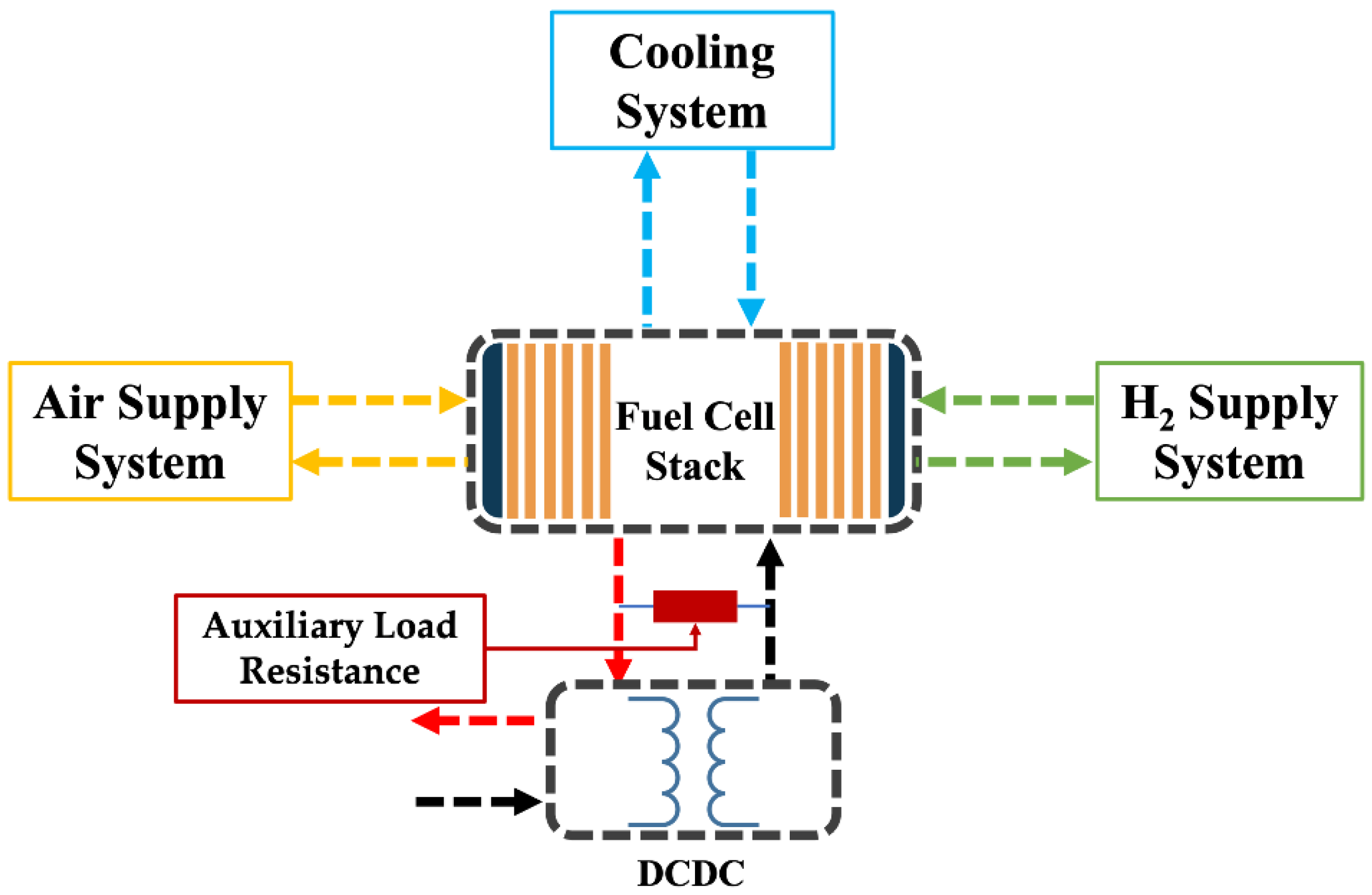
2.1. The PEMFC Stack Parameters and Experimental Test Platform

In this work, the experiment was performed on a PEMFC system combined by our group. Additionally, a commercial PEMFC stack with liquid-cooled manufactured by Sinosynergy Co., Ltd. (Foshan, China) was used in the test. The main parameters of the PEMFC stack are displayed in Table 1.
The schematic diagram of the PEMFC system testbench is shown in Figure 1, which consisted of hydrogen, air, and cooling systems. The fuel cell system generally consists of hydrogen, air, and cooling subsystems. The air supply system includes an air compressor, a cooler, and a humidifier, which is mainly responsible for providing air to the fuel cell. The hydrogen supply system includes a water separator, a recirculation pump, and a hydrogen exhaust valve, which is mainly responsible for supplying hydrogen to the fuel cell. The cooling supply system includes an ion filter, a water tank, and a radiator, which is primarily responsible for supplying coolant to the fuel cell. The water management system is contained in the air supply system and the hydrogen supply system. A humidifier is used in the air supply system to adjust the humidity of the air, and a recirculation pump and a water separator are used in the hydrogen supply system to adjust the humidity of the hydrogen. Meanwhile, to continue consuming the residual oxygen in the PEMFC stack after the DCDC is shut down, an auxiliary load resistance is added between the DCDC and PEMFC stack. The main parameters of the PEMFC system testbench were displayed in Table 2. When the input voltage of the DCDC is lower than 20 V, the DCDC stops working.

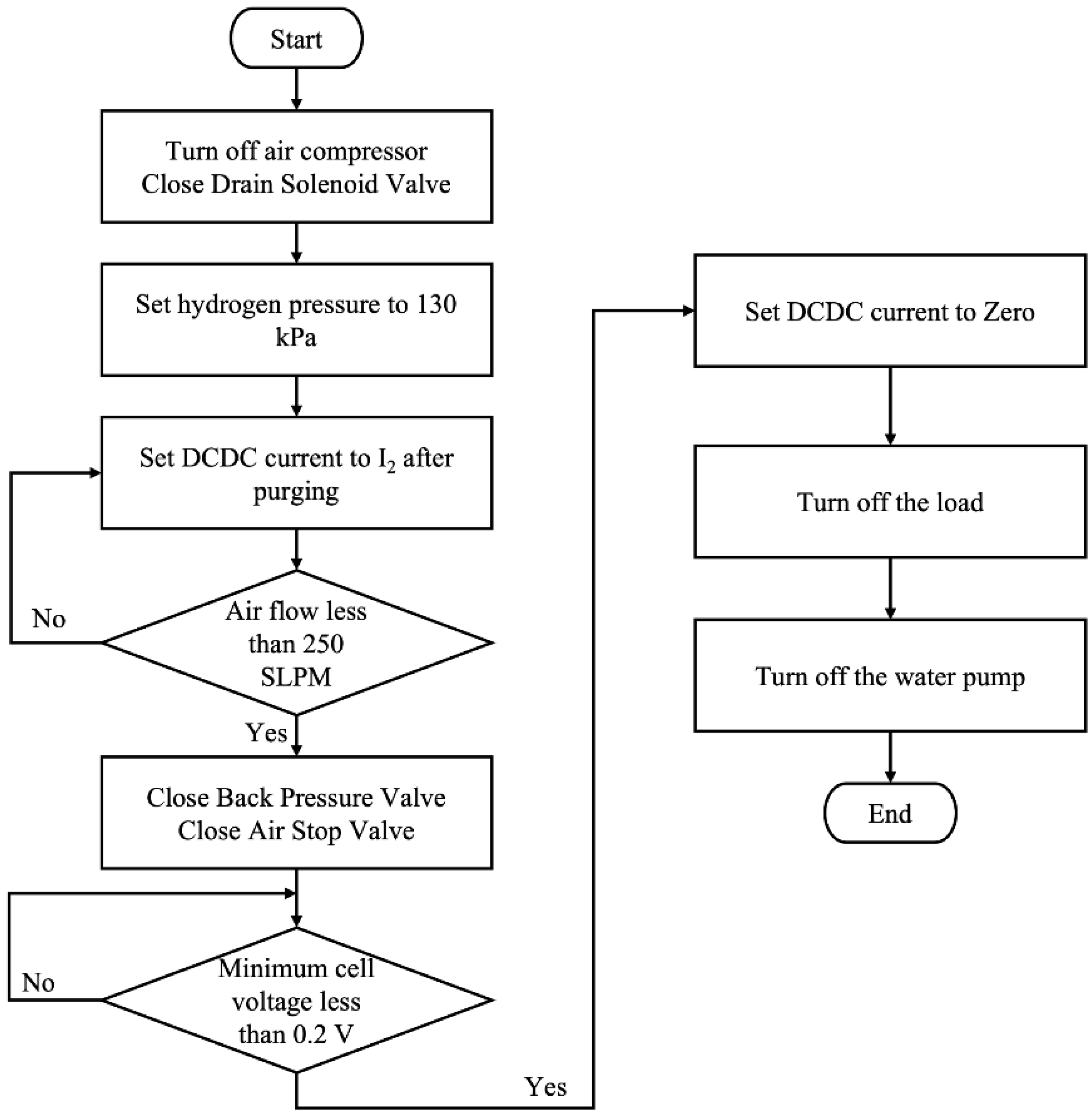
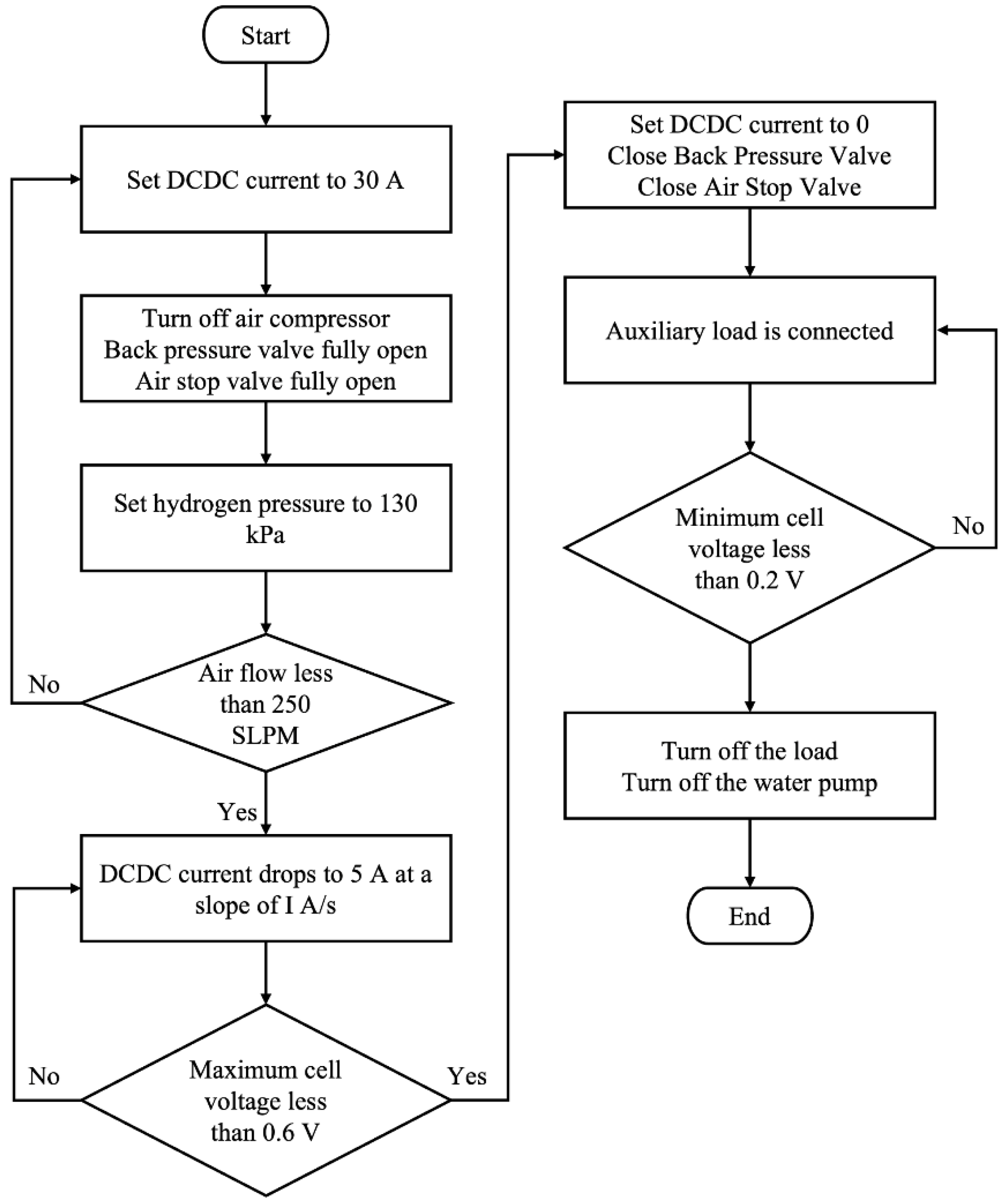
2.2. Procedure of the Experimental Test

In this work, the shutdown process of the fuel cell system after purging is mainly investigated. Firstly, the PEMFC system is tested with an unoptimized shutdown strategy and the experimental flow chart of the unoptimized shutdown strategy is shown in Figure 2. In the unoptimized shutdown strategy, the DCDC current is set to 30 A during the gas purging. Then, the DCDC current is adjusted to 5 A after gas purging. After that, when the air flow drops to 250 SLPM, the back pressure valve and air stop valve are closed. Until the single-cell voltage is lower than 0.2 V, the DCDC current is adjusted to 0 A and the shutdown process is finished. Secondly, the auxiliary load resistance and the discharge current drop rate are optimized and the experimental flow chart of the optimized shutdown strategy is shown in Figure 3. In this shutdown strategy, the DCDC current is set to 30 A during the gas purging. Then, the DCDC current is adjusted to a specific discharge current drop rate until the current drops to 5 A after gas purging. When the single-cell voltage is lower than 0.6 V, the DCDC current is adjusted to 0 A and the auxiliary load is connected. Simultaneously, the back pressure valve and air stop valve are closed. Once the single-cell voltage becomes lower than 0.2 V, the shutdown process is finished.
Before the test, the PEMFC system was purged to remove the water in the stack. During the gas purging, the DCDC current is set to 30 A. Meanwhile, the flow rate of air is 2000 SLPM and the pressure of hydrogen (H2) is 130 kPa.a with a 0.5 s period of gas exhaust. After gas purging, the DCDC current decreased to 5 A. When the single-cell voltage reaches 0.2 V, the auxiliary load is shut down.
In order to optimize the shutdown strategy of the fuel cell system, 9 cases of experiments were designed to optimize the discharge current drop rate and auxiliary load resistance value. Case 1 is the test for an unoptimized shutdown strategy. Case 2 to case 4 are the test for optimizing the discharge current drop rate. Case 5 to case 9 are the test for optimizing the auxiliary load resistance value. The shutdown operating parameters of the PEMFC system are displayed in Table 3.

3. Results and Discussion

In this section, the different drop rate of the discharge current and auxiliary load resistance was studied to obtain an optimized operating condition of the fuel cell shutdown control strategy. By optimizing the parameters, it is hoped that residual oxygen in the PEMFC can be consumed rapidly and completely, and the operating time at the high potential in the shutdown process can be shortened.

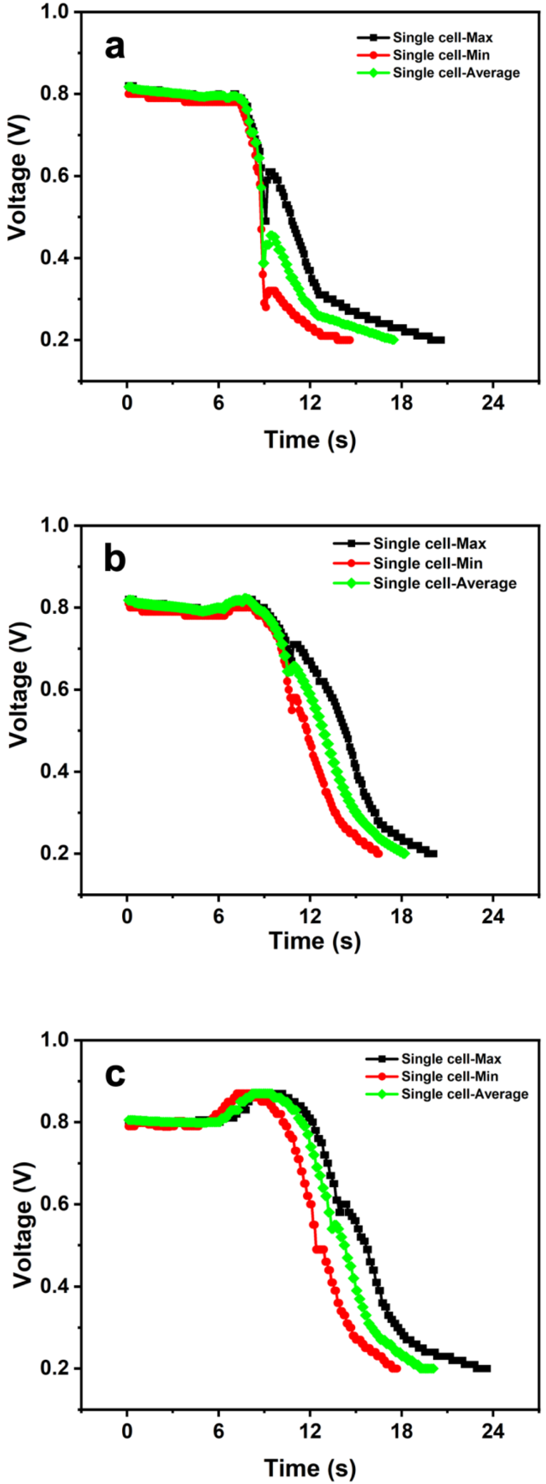
3.1. Impact of the Fuel Cell Drop Rate of the Discharge Current during Shutdown Process

To study the influence of the different drop rates of the discharge current on the PEMFC shutdown process, 5 A/s, 7 A/s, and 10 A/s were investigated as the discharge current drop rates of the PEMFC for experiments. Case 2 to Case 4 were the experimental operating parameters, which are shown in Table 3.
Figure 4 displayed the curve of the single-cell voltage during the shutdown process of the PEMFC system at different discharge current drop rates. On one hand, the results show that the shutdown time of PEMFC system was the longest at a 10 A/s discharge current drop rate. When the current started to decline at a discharge current drop rate of 10 A/s, the discharge current of the PEMFC dropped to 5 A rapidly. Meanwhile, the single-cell voltage of the PEMFC was rising and the highest voltage was 0.87 V. The reason for this was that when the current of the PEMFC stack started to drop, the current was greater than 5 A, which could rapidly consume oxygen in the catalytic layer or even the gas diffusion layer of the PEMFC stack. However, as the current declined too fast to 5 A, the oxygen in the catalytic layer and gas diffusion layer of the PEMFC stack could not be consumed rapidly when under the operating current of 5 A. Thus, the residual oxygen in the flow field of the PEMFC stack could be replenished to the gas diffusion layer and the catalytic layer in time, and the cathode electrode potential is re-established. Meanwhile, the polarization of the PEMFC stack decreased under the operating current of 5 A, resulting in an increase in the PEMFC voltage. On the other hand, when the current drop rate is adjusted to 5 A/s, the shutdown time of the PEMFC system was the shortest and the single-cell voltage of the PEMFC did not rise above 0.8 V during the shutdown process, which effectively alleviated the agglomeration of platinum particles and carbon corrosion. However, at a time of 10 s, the voltage of the single cell rebounded. Meanwhile, the relationship between the current and voltage of the PEMFC during the shutdown process at a discharge current drop rate is displayed in Figure 5. Based on the discharge current drop rate of 10 A/s (Figure 5a), the time for the current to drop from 30 A to 5 A is 2.7 s, which can prove that the DCDC adopted in the fuel cell system has good current control accuracy to ensure the discharge current drop rate required in this work. After the DCDC current dropped to 5 A, the constant discharge process was carried out until the single-cell voltage dropped to 0.6 V. Then, the DCDC current dropped to 0 A and the residual oxygen in the PEMFC was consumed by the auxiliary load until the single-cell voltage dropped to 0.2 V. However, when the current of the PEMFC dropped to 12 A at a discharge current drop rate of 5 A/s, the maximum single-cell voltage of the PEMFC was lower than 0.6 V, which is displayed in Figure 5b. Additionally, this situation led to the direct shutdown of DCDC without the 5 A constant-current discharge to consume the remaining oxygen. At the same time, the sudden disappearance of the DCDC current caused the recovery of the single-cell voltage.
Moreover, the consistency of the PEMFC stack at different discharge current drop rates is shown in Figure 6. A large discharge current drop rate means a small discharge current, which results in a better consistency of each cell in the PEMFC stack during the shutdown process. However, the large discharge current drop rate could also result in a long operating time at a high potential. Combined with the experimental results in Figure 4 and Figure 6, the discharge current drop rate of 7 A/s could shorten the operating time of the PEMFC at a high potential. Thus, 7 A/s was selected as the best discharge current drop rate for the shutdown process of the PEMFC system and was used as the discharge current drop rate in the subsequent experiments.

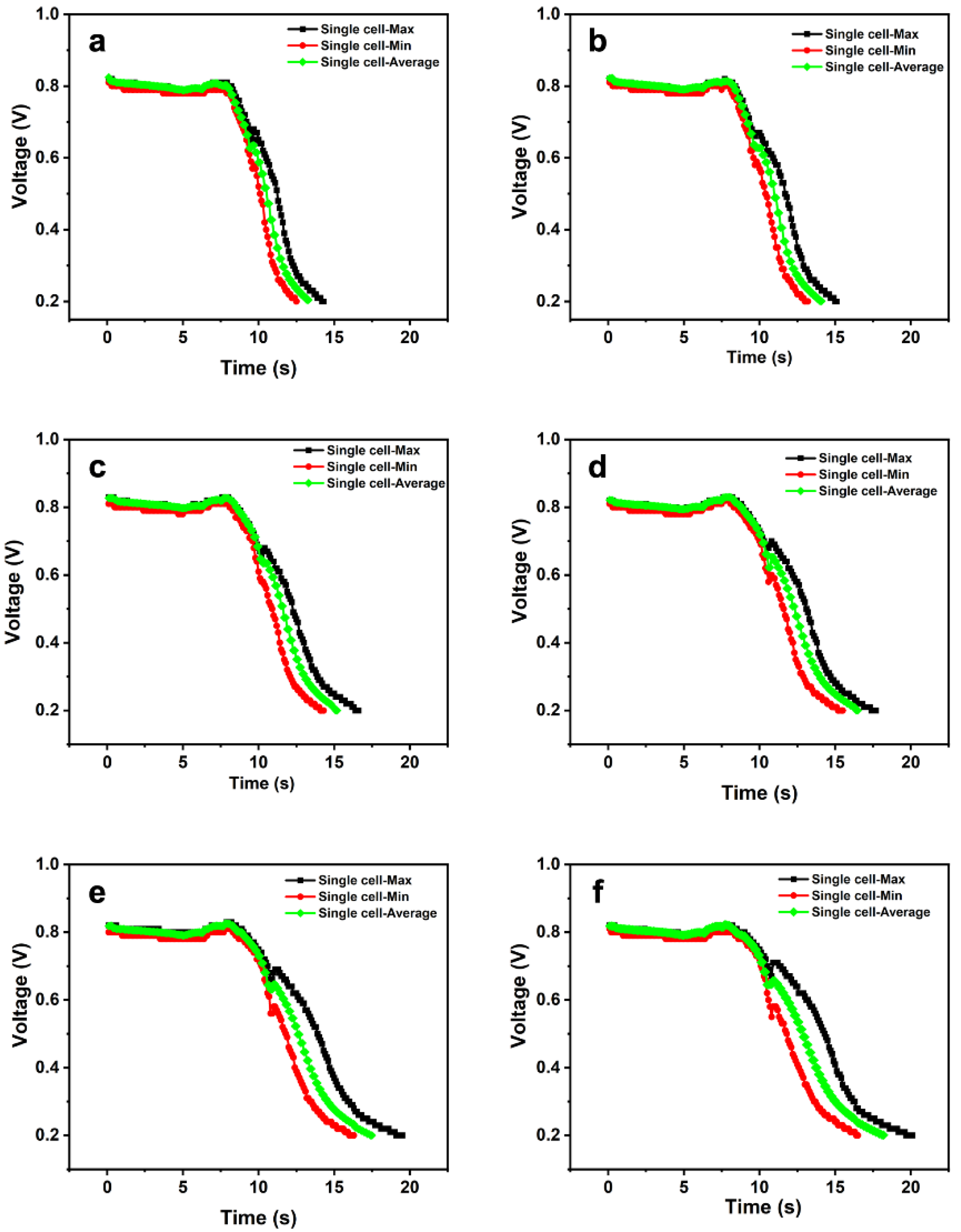
3.2. Impact of the Auxiliary Load Resistance on Shutdown Process

Based on the optimization analysis of the discharge current drop rate of the PEMFC stack in the previous section, the optimal discharge current drop rate of the PEMFC stack is obtained in this shutdown strategy. However, in addition to the uniformity and voltage increase in single cells in the PEMFC stack, the reduction in discharge time should also be considered during the shutdown process. Thus, in the shutdown strategy mentioned in our study, the auxiliary load resistance is also one of the key factors affecting the shutdown process of the PEMFC system to accelerate the consumption of residual oxygen in the PEMFC stack and shorten the discharge time.
In this section, the auxiliary load resistance values of 50 Ω, 60 Ω, 80 Ω, 100 Ω, 120 Ω, and 150 Ω were, respectively, used in the experiments to investigate the effect of the auxiliary load on the shutdown strategy of the PEMFC system and Case 4 to Case 9 were the experimental operating parameters which are shown in Table 3. Meanwhile, the relationship between the auxiliary load resistance and the shutdown discharge characteristics is exhibited in Figure 7. Evidently, the discharge characteristics of different auxiliary load resistance values have the same tendency, and the smaller the auxiliary load resistance value, the shorter the shutdown time. This means that the smaller the auxiliary load resistance value in the discharge process, the larger the discharge current, resulting in a high rate of oxygen consumption. Under the auxiliary load resistance value of 50 Ω, the shutdown time of the PEMFC system was 13.5 s. With the increase in resistance value, the shutdown times of the PEMFC system were 14.1 s, 15.3 s, 16.8 s, 17.9 s, and 18.6 s. Moreover, the consistency of the PEMFC stack at different auxiliary load resistance values was discussed. As shown in Figure 8, the PEMFC stack demonstrated good consistency in discharging with different auxiliary load resistance values. Additionally, the smaller the auxiliary load resistance value, the better the consistency of the PEMFC. In other words, the PEMFC has the best consistency when the auxiliary load resistance value is 50 Ω. Therefore, combined with the experimental results in Figure 7 and Figure 8, 50 Ω was selected as the best auxiliary load resistance value for the shutdown process of the PEMFC system.

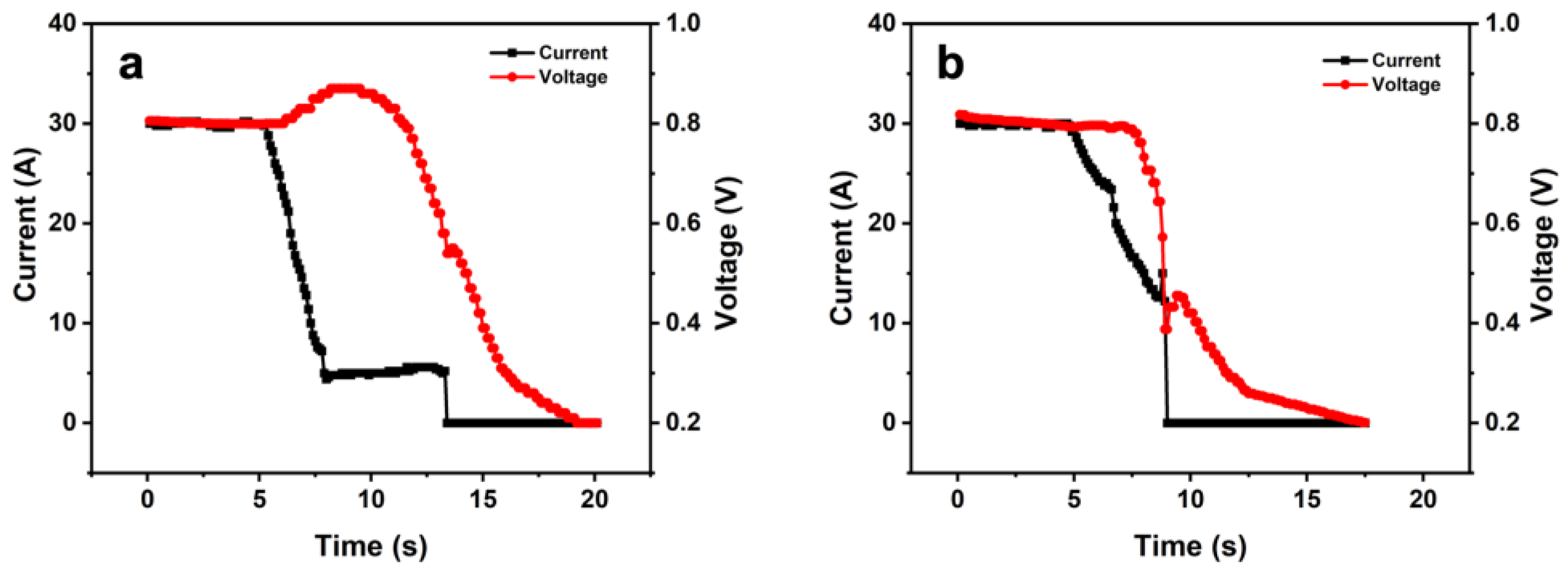
3.3. Comparison of Shutdown Strategy of the PEMFC System before and after Optimization

To survey the effect of the optimized shutdown strategy, the discharge characteristics of the unoptimized shutdown strategy and the optimized shutdown strategy were compared in Figure 9. On one hand, the shutdown time of the PEMFC system was 18.4 s before the downtime strategy was optimized. Meanwhile, the maintenance time of single-cell voltage above 0.82 V in the PEMFC stack during the shutdown process was 10.9 s. The reason for this is that the shutdown process of the air compressor has a hysteresis effect, and there is still air entering the fuel cell after closing the air compressor. At this time, the PEMFC stack is full of oxygen. When the DCDC discharge current drops directly to 5 A, the residual oxygen consumption rate in the PEMFC stack slows down. Simultaneously, the continuous supply of oxygen from the air compressor causes the PEMFC stack to work for a long time at a single-cell voltage above 0.8 V, resulting in a prolonged shutdown time of the PEMFC system. On the other hand, in order to avoid the excessive oxygen caused by the hysteresis of the air compressor, in the optimized shutdown strategy, the discharge current of DCDC was reduced at a rate of 7 A/S after the air flow dropped to 250 SLPM. Then, the shutdown time of the PEMFC system was 13.5 s after the downtime strategy was optimized. Additionally, the maintenance time of single-cell voltage above 0.82 V in the PEMFC stack during the shutdown process was 0.1 s, shortening the operating time of the PEMFC above 0.8 V. Additionally, the detail of these results is shown in Table 4. Thus, the optimized shutdown strategy can effectively reduce the residual oxygen consumption time in the PEMFC stack and the time that the PEMFC stack stays at high potential during the shutdown process, which ultimately shortens the shutdown time of the PEMFC system.

4. Conclusions

In this work, a shutdown strategy of the PEMFC system is studied to consume the residual oxygen in the PEMFC stack rapidly and shorten the operating time of the PEMFC at high potential. After the PEMFC system experiment, the optimized value of the discharge current drop rate and the auxiliary load resistance are obtained. As for the discharge current drop rate, the optimized value is 7 A/s, which can control the voltage of a single cell below 0.8 V during the discharge current drop and results in better consistency of each cell in the PEMFC stack during the shutdown process. Meanwhile, under the auxiliary load resistance value of 50 Ω, the shutdown time of the PEMFC system was 13.5 s and the maintenance time of the single-cell voltage above 0.82 V in the PEMFC stack during the shutdown process was 0.1 s. In addition, the PEMFC stack demonstrated good consistency in discharging with the discharge current drop rate of 7 A/s and the auxiliary load resistance values of 50 Ω. Thus, the optimized shutdown strategy with a discharge current drop rate at 7 A/s and an auxiliary load resistance value at 50 Ω can effectively reduce the shutdown time of the PEMFC system and the time that the fuel cell stack stays at high potential during the shutdown process, so as to rapidly consume the residual oxygen and reduce the degradation in the PEMFC. Moreover, these results can reduce the shutdown time of the fuel cell system for vehicles without adding additional components and costs, while improving the durability of the PEMFC and contributing to the development of fuel cell vehicles.

Author Contributions

Conceptualization, J.F., Y.Y. and T.M.; Data curation, J.F. and Y.Y.; Methodology, J.F.; Project administration, Y.Y. and T.M.; Formal analysis, J.F. and Y.Y.; Investigation, Y.Y.; Resources, T.M.; Supervision, Y.Y. and T.M.; Validation, J.F. and Y.Y.; Visualization, Y.Y.; Writing—original draft, J.F.; Writing—review and editing, D.Z. and X.X. All authors have read and agreed to the published version of the manuscript.

Funding

This research received no external funding.

Institutional Review Board Statement

Not applicable.

Informed Consent Statement

Not applicable.

Data Availability Statement

There is no new data.

Conflicts of Interest

The authors declare no conflict of interest. The funders had no role in the design of the study; in the collection, analyses, or interpretation of data; in the writing of the manuscript, or in the decision to publish the results.

References

  1. Herc, L.; Pfeifer, A.; Duić, N. Optimization of the possible pathways for gradual energy system decarbonization. Renew. Energ. 2022, 193, 617–633. [Google Scholar] [CrossRef]
  2. Sun, C.; Zhang, H. Review of the Development of First-Generation Redox Flow Batteries: Iron-Chromium System. ChemSusChem 2022, 15, e202101798. [Google Scholar] [CrossRef] [PubMed]
  3. Kim, J.; Huh, C.; Seo, Y. End-to-end value chain analysis of isolated renewable energy using hydrogen and ammonia energy carrier. Energ. Convers. Manag. 2022, 254, 115247. [Google Scholar] [CrossRef]
  4. Huang, Z.; Shen, J.; Chan, S.H.; Tu, Z. Transient response of performance in a proton exchange membrane fuel cell under dynamic loading. Energ. Convers. Manag. 2020, 226, 113429. [Google Scholar] [CrossRef]
  5. Zhu, D.; Ma, T.; Yang, Y. Optimization and application of the distribution of relaxation times based on characteristic frequency resolution and hyperparameters. J. Power Sources 2022, 545, 231955. [Google Scholar] [CrossRef]
  6. Zhu, D.; Yang, Y.; Pei, F.; Ma, T. High-precision identification of polarization processes of distribution of relaxation times by polarization curve model for proton exchange membrane fuel cell. Energ. Convers. Manag. 2022, 268, 115994. [Google Scholar] [CrossRef]
  7. Wu, J.; Yuan, X.Z.; Martin, J.J.; Wang, H.Z.; Hang, J.; Shen, J.; Wu, S.; Merida, W. A review of PEM fuel cell durability: Degradation mechanisms and mitigation strategies. J. Power Sources 2008, 184, 104–119. [Google Scholar] [CrossRef]
  8. Zhao, J.; Li, X. A review of polymer electrolyte membrane fuel cell durability for vehicular applications: Degradation modes and experimental techniques. Energ. Convers. Manag. 2019, 199, 112022. [Google Scholar] [CrossRef]
  9. Pei, P.; Chang, Q.; Tang, T. A quick evaluating method for automotive fuel cell lifetime. Int. J. Hydrogen Energy 2008, 33, 3829–3836. [Google Scholar] [CrossRef]
  10. Zhang, T.; Wang, P.; Chen, H.; Pei, P. A review of automotive proton exchange membrane fuel cell degradation under start-stop operating condition. Appl. Energy 2018, 223, 249–262. [Google Scholar] [CrossRef]
  11. Ma, T.; Zhu, D.; Xie, J.; Lin, W.; Yang, Y. Investigation on a parking control strategy for automotive proton exchange membrane fuel cell. Fuel Cells 2021, 21, 390–397. [Google Scholar] [CrossRef]
  12. Stevens, D.A.; Hicks, M.T.; Haugen, G.M.; Dahn, J.R. Ex Situ and In Situ Stability Studies of PEMFC Catalysts. J. Electrochem. Soc. 2005, 152, A2309–A2315. [Google Scholar] [CrossRef]
  13. Guilminot, E.; Corcella, A.; Charlot, F.; Maillard, F.; Chatenet, M. Detection of Ptz+ Ions and Pt Nanoparticles Inside the Membrane of a Used PEMFC. J. Electrochem. Soc. 2007, 154, B96–B105. [Google Scholar] [CrossRef]
  14. Jung, G.-B.; Chuang, K.-Y.; Jao, T.-C.; Yeh, C.-C.; Lin, C.-Y. Study of high voltage applied to the membrane electrode assemblies of proton exchange membrane fuel cells as an accelerated degradation technique. Appl. Energy 2012, 100, 81–86. [Google Scholar] [CrossRef]
  15. Lamibrac, A.; Maranzana, G.; Lottin, O.; Dillet, J.; Mainka, J.; Didierjean, S.; Thomas, A.; Moyne, C. Experimental characterization of internal currents during the start-up of a proton exchange membrane fuel cell. J. Power Sources 2011, 196, 9451–9458. [Google Scholar] [CrossRef]
  16. Tang, H.; Qi, Z.; Ramani, M.; Elter, J.F. PEM fuel cell cathode carbon corrosion due to the formation of air/fuel boundary at the anode. J. Power Sources 2006, 158, 1306–1312. [Google Scholar] [CrossRef]
  17. Yu, Y.; Tu, Z.; Zhang, H.; Zhan, Z.; Pan, M. Comparison of degradation behaviors for open-ended and closed proton exchange membrane fuel cells during startup and shutdown cycles. J. Power Sources 2011, 196, 5077–5083. [Google Scholar] [CrossRef]
  18. Oh, H.-S.; Oh, J.-G.; Haam, S.; Arunabha, K.; Roh, B.; Hwang, I.; Kim, H. On-line mass spectrometry study of carbon corrosion in polymer electrolyte membrane fuel cells. Electrochem. Commun. 2008, 10, 1048–1051. [Google Scholar] [CrossRef]
  19. Genorio, B.; Strmcnik, D.; Subbaraman, R.; Tripkovic, D.; Karapetrov, G.; Stamenkovic, V.R.; Pejovnik, S.; Markovic, N.M. Selective catalysts for the hydrogen oxidation and oxygen reduction reactions by patterning of platinum with calix [4] arene molecules. Nat. Mater. 2010, 9, 998–1003. [Google Scholar] [CrossRef]
  20. Ishigami, Y.; Takada, K.; Yano, H.; Inukai, J.; Uchida, M.; Nagumo, Y.; Hyakutake, T.; Nishide, H.; Watanabe, M. Corrosion of carbon supports at cathode during hydrogen/air replacement at anode studied by visualization of oxygen partial pressures in a PEFC—Start-up/shut-down simulation. J. Power Sources 2011, 196, 3003–3008. [Google Scholar] [CrossRef]
  21. Eom, K.; Jo, Y.Y.; Cho, E.; Lim, T.-H.; Jang, J.H.; Kim, H.-J.; Hong, B.K.; Lee, J.H. Effects of residual oxygen partial pressure on the degradation of polymer electrolyte membrane fuel cells under reverse current conditions. J. Power Sources 2012, 198, 42–50. [Google Scholar] [CrossRef]
  22. Oyarce, A.; Zakrisson, E.; Ivity, M.; Lagergren, C.; Ofstad, A.B.; Bodén, A.; Lindbergh, G. Comparing shut-down strategies for proton exchange membrane fuel cells. J. Power Sources 2014, 254, 232–240. [Google Scholar] [CrossRef]
  23. Yu, Y.; Wang, G.; Tu, Z.; Zhan, Z.; Pan, M. Effect of gas shutoff sequences on the degradation of proton exchange membrane fuel cells with dummy load during startup and shutdown cycles. Electrochim. Acta 2012, 71, 181–193. [Google Scholar] [CrossRef]
  24. Lin, R.; Liu, D.; Xia, S.; Ma, T.; Dutruel, B. Stack shut-down strategy optimisation of proton exchange membrane fuel cell with the segment stack technology. Int. J. Hydrogen Energy 2020, 45, 1030–1044. [Google Scholar] [CrossRef]
  25. Schneider, I.A.; von Dahlen, S. Start-Stop Phenomena in Channel and Land Areas of a Polymer Electrolyte Fuel Cell. Electrochem. Solid-State Lett. 2011, 14, B30–B33. [Google Scholar] [CrossRef]
  26. Kim, J.H.; Cho, E.A.; Jang, J.H.; Kim, H.J.; Lim, T.H.; Oh, I.H.; Ko, J.J.; Son, I.-J. Development of a Durable PEMFC Start-Up Process by Applying a Dummy Load- II. Diagnostic Study. J. Electrochem. Soc. 2010, 157, B118–B124. [Google Scholar] [CrossRef]
  27. Linse, N.; Scherer, G.G.; Wokaun, A.; Gubler, L. Quantitative analysis of carbon corrosion during fuel cell start-up and shut-down by anode purging. J. Power Sources 2012, 219, 240–248. [Google Scholar] [CrossRef]
  28. Kim, J.H.; Cho, E.A.; Jang, J.H.; Kim, H.J.; Lim, T.-H.; Oh, I.-H.; Ko, J.J.; Oh, S.C. Development of a Durable PEMFC Startup Process by Applying a Dummy Load- I. Electrochemical Study. J. Electrochem. Soc. 2009, 156, B955–B961. [Google Scholar] [CrossRef]
  29. Kim, H.-J.; Lim, S.J.; Lee, J.W.; Min, I.-G.; Lee, S.-Y.; Cho, E.; Oh, I.-H.; Lee, J.H.; Oh, S.-C.; Lim, T.-W.; et al. Development of shut-down process for a proton exchange membrane fuel cell. J. Power Sources 2008, 180, 814–820. [Google Scholar] [CrossRef]
Figure 1. The schematic diagram of the PEMFC system testbench.
Energies 16 01285 g001
Figure 2. The experimental flow chart of unoptimized shutdown strategy.
Energies 16 01285 g002
Figure 3. The experimental flow chart of optimized shutdown strategy.
Energies 16 01285 g003
Figure 4. Influence of the different drop rates of the discharge current on the PEMFC shutdown process.
Energies 16 01285 g004
Figure 5. The relationship between the current and voltage of the PEMFC during the shutdown process at a discharge current drop rate. (a) 10 A/s, (b) 5 A/s.
Energies 16 01285 g005
Figure 6. The consistency of the PEMFC stack at different discharge current drop rates. (a) 5 A/s, (b) 7 A/s, (c) 10 A/s.
Energies 16 01285 g006
Figure 7. Influence of the different auxiliary load resistance on the PEMFC shutdown process.
Energies 16 01285 g007
Figure 8. The consistency of the PEMFC stack at different auxiliary load resistance values. (a) 50 Ω, (b) 60 Ω, (c) 80 Ω, (d) 100 Ω, (e) 120 Ω, (f) 150 Ω.
Energies 16 01285 g008
Figure 9. Comparison of discharge characteristics between the unoptimized and the optimized shutdown strategy.
Energies 16 01285 g009
Table 1. The parameters of the PEMFC stack.
NameParameters
Type9 ssl
Single-cell number135
Active area285 cm2
Hydrogen/air stoichiometry1.5/2
Working temperature60 °C
Working relative humidity100%
Cooling typeLiquid-cooled
Maximum power27 kW
Bipolar plateGraphite
Flow fieldCocurrent flow
Table 2. The parameters of the PEMFC system testbench.
NameParameters
Current of the PEMFC stack0~300 A
Voltage of the PEMFC stack0~130 V
Flow rate of the hydrogen0~500 SLPM
Relative humidity of the hydrogen40~100%
Pressure of the hydrogen0~160 kPa.a
Flow rate of the air0~1500 SLPM
Pressure of the air0~150 kPa.a
Relative humidity of the air40~100%
Flow rate of coolant0~50 SLPM
Temperature of coolant60~65 °C
Protection voltage of DCDC20 V
Table 3. Shutdown operating parameters of the PEMFC system in a different case.
Case No.Auxiliary Load Resistance (Ω)Current Drop Rate (A/s)
1--
215010
31505
41507
5507
6607
7807
81007
91207
Table 4. Discharge characteristics parameters between the unoptimized and the optimized shutdown strategy.
Auxiliary Load Resistance (Ω)Shutdown Time (s)Potential Maintenance Time above 0.82 V (s)
-18.410.9
5013.50.1
Disclaimer/Publisher’s Note: The statements, opinions and data contained in all publications are solely those of the individual author(s) and contributor(s) and not of MDPI and/or the editor(s). MDPI and/or the editor(s) disclaim responsibility for any injury to people or property resulting from any ideas, methods, instructions or products referred to in the content.

