
Review on Test Benches Studying Sliding Electrical Contact and Synthesis of Experimental Results
 ,
,
Abstract
:1. Introduction
2. A Variety of Experimental Setups
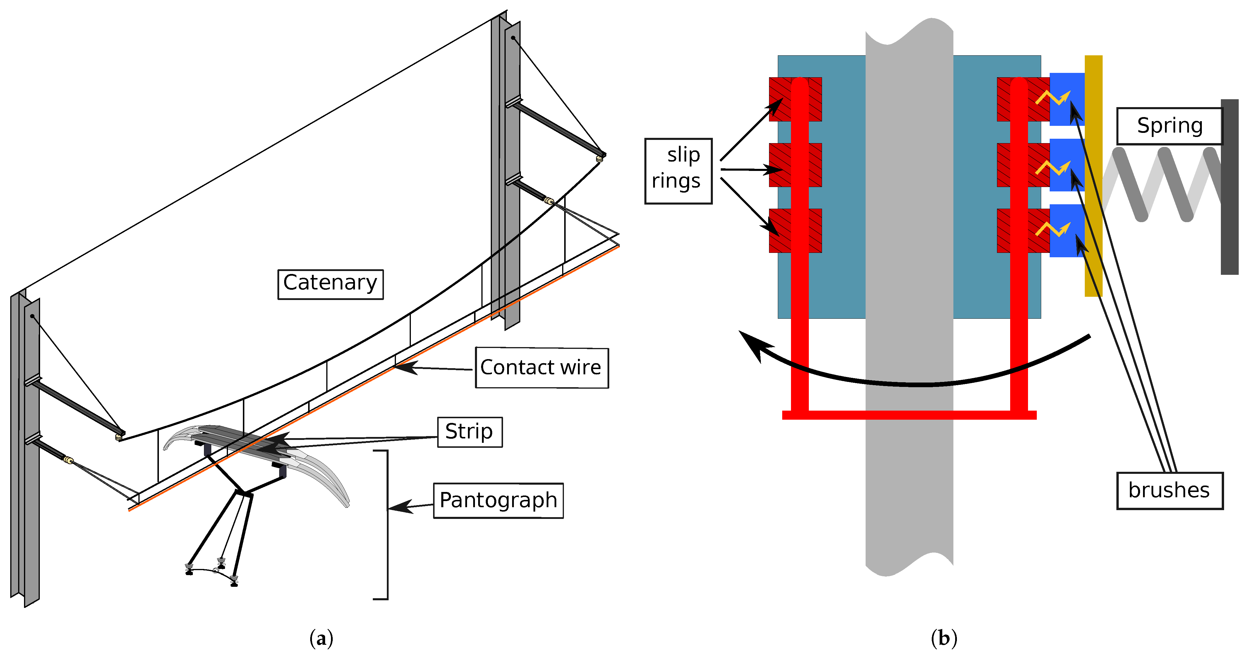
2.1. Experimental Study of Pantograph–Catenary Contacts
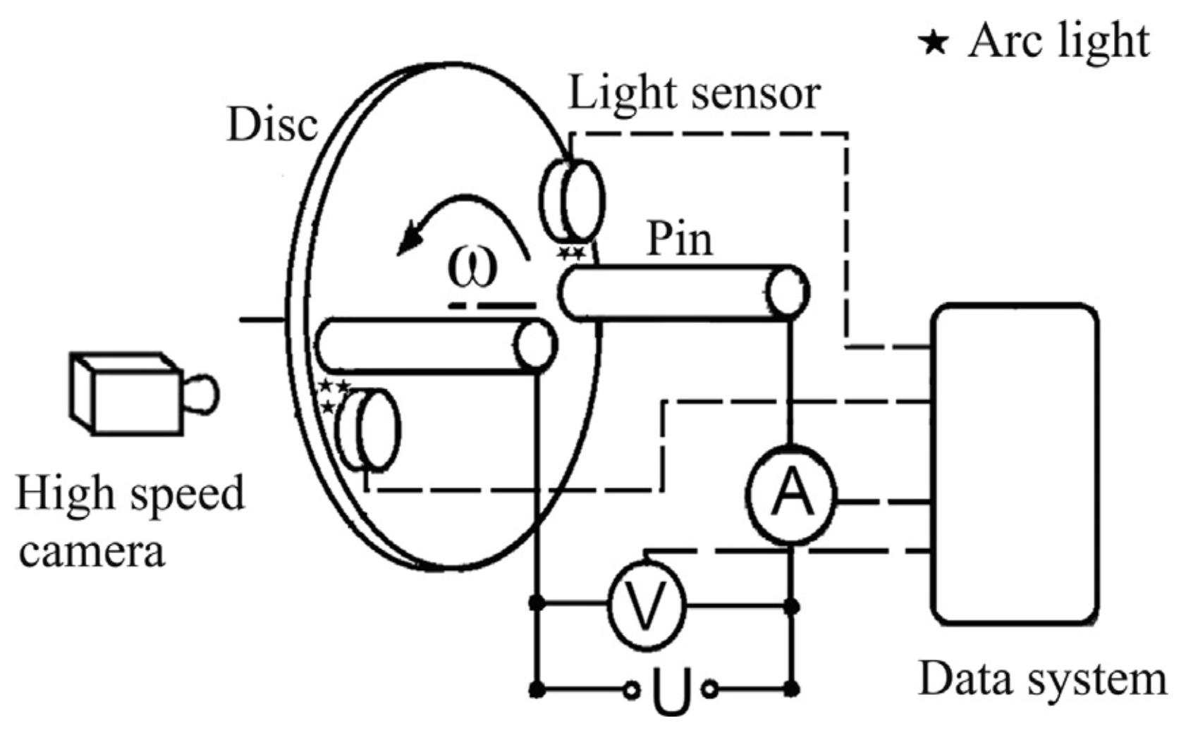
2.1.1. Current-Carrying Friction and Wear Tester Pin-on-Disc Tribometer
2.1.2. Ring Block-Type Test Machine
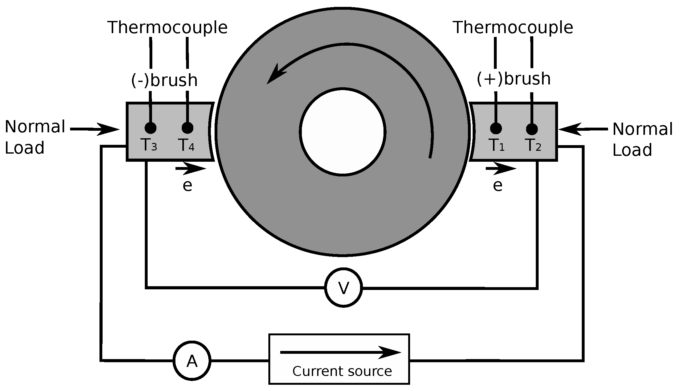
2.1.3. Full-Scale Experimental Ring Block
2.2. Experimental Study of Slip Rings
2.2.1. Studies of a Sliding Electrical Contact at Low Speed
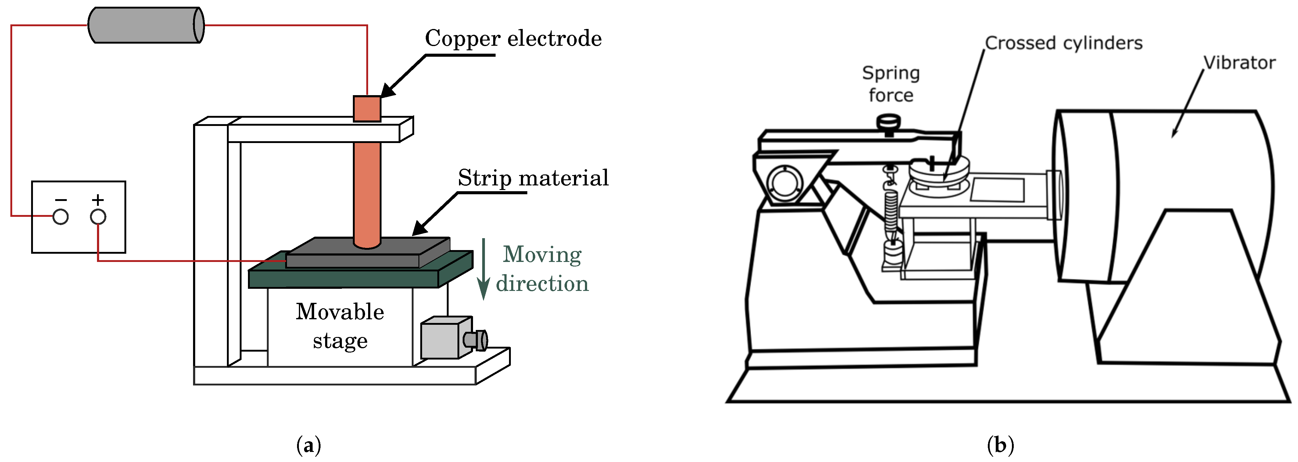
2.2.2. Tribological Testing Device
2.2.3. Slip Ring Brush Tribostester
2.3. Other Studies of Electrical Sliding Contacts
Electrical Arc Generation
2.4. Conclusions
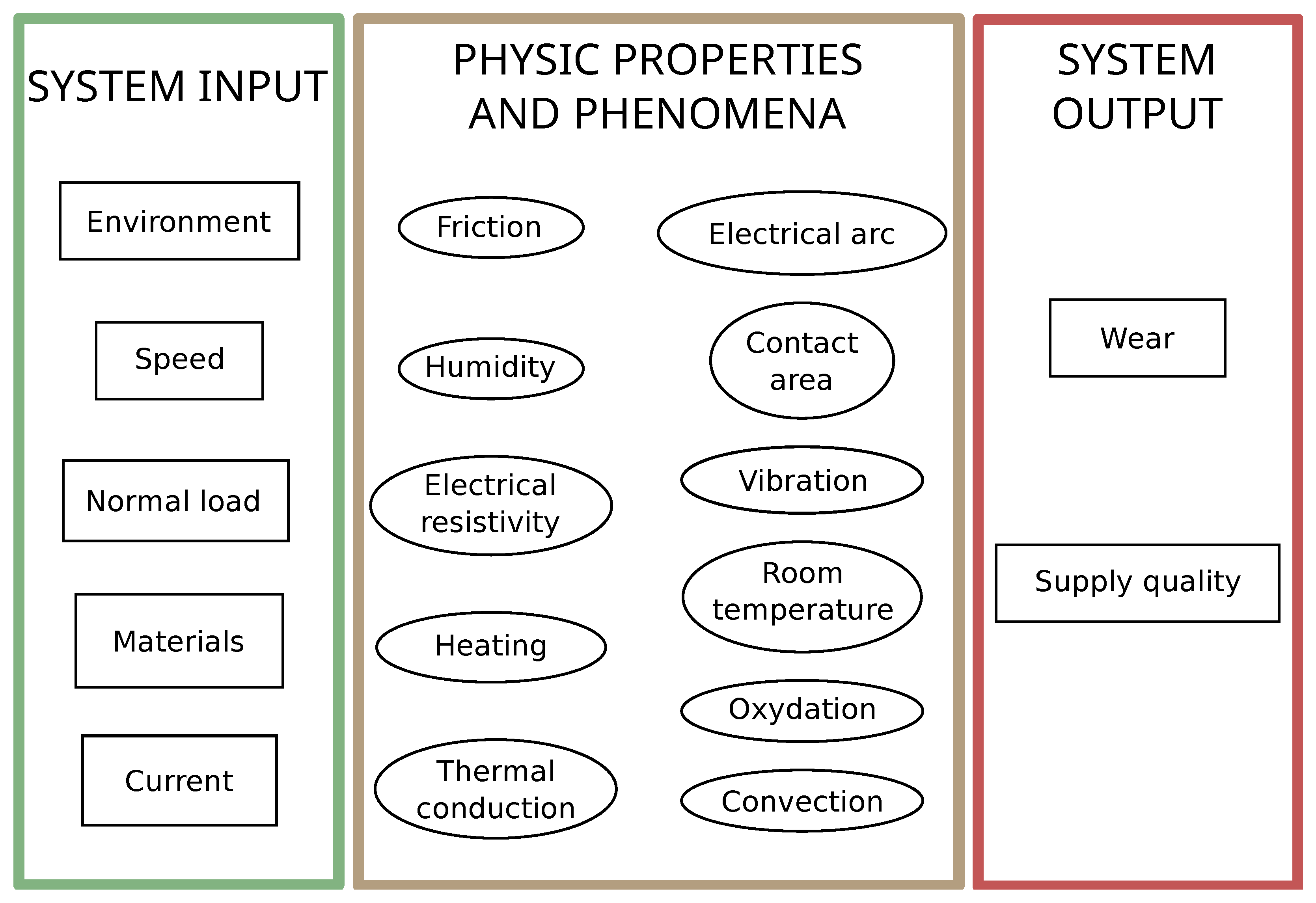
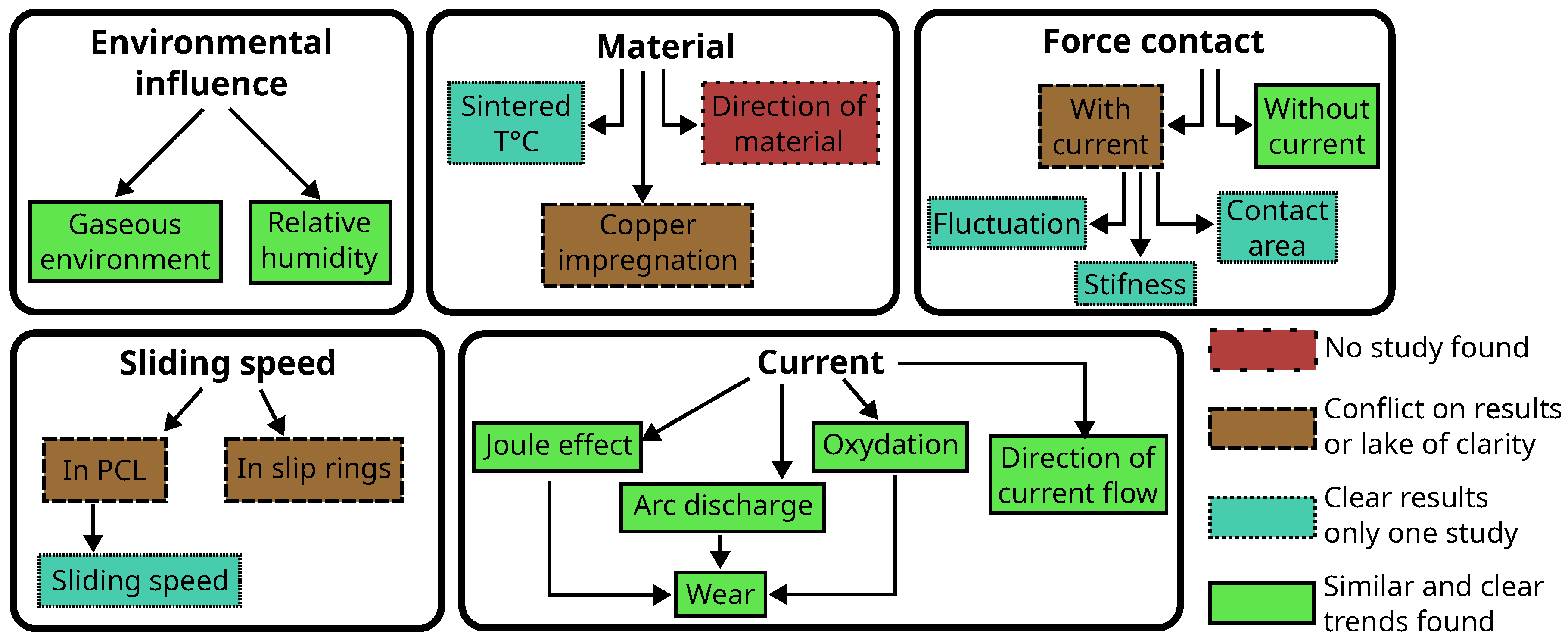
3. Discussion
3.1. Environmental Influences
3.1.1. Ambient Temperature
3.1.2. Gaseous Environment
3.2. Strip/Brush Material
3.2.1. Sintered Temperature
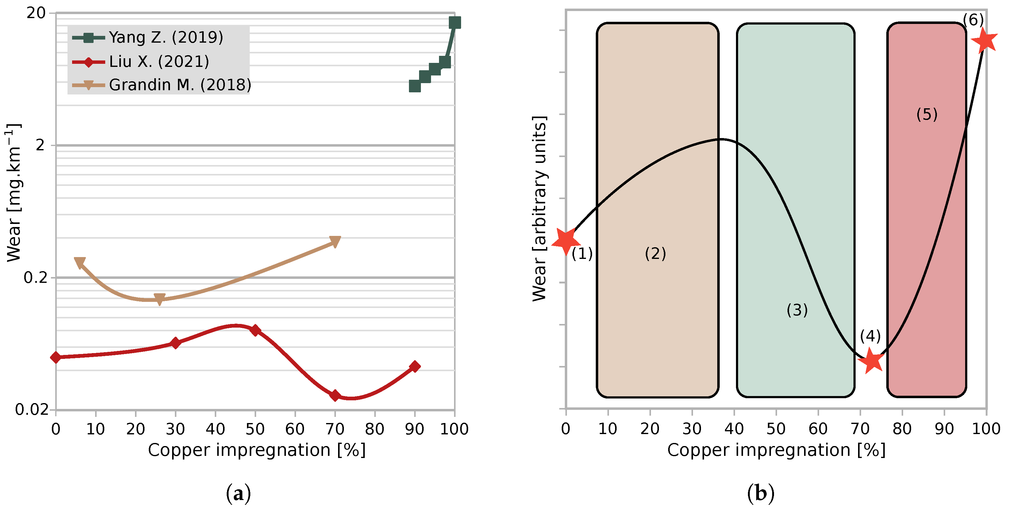
3.2.2. Copper Impregnation
- As for the optimal point, the amount of copper is different from one author to the other.
- The effects on the friction coefficient and the wear rate of the copper oxide CuO found on the surface are still unclear.
- Authors did not observe the same wear rate trend at low amounts of copper content.
3.3. Normal Load
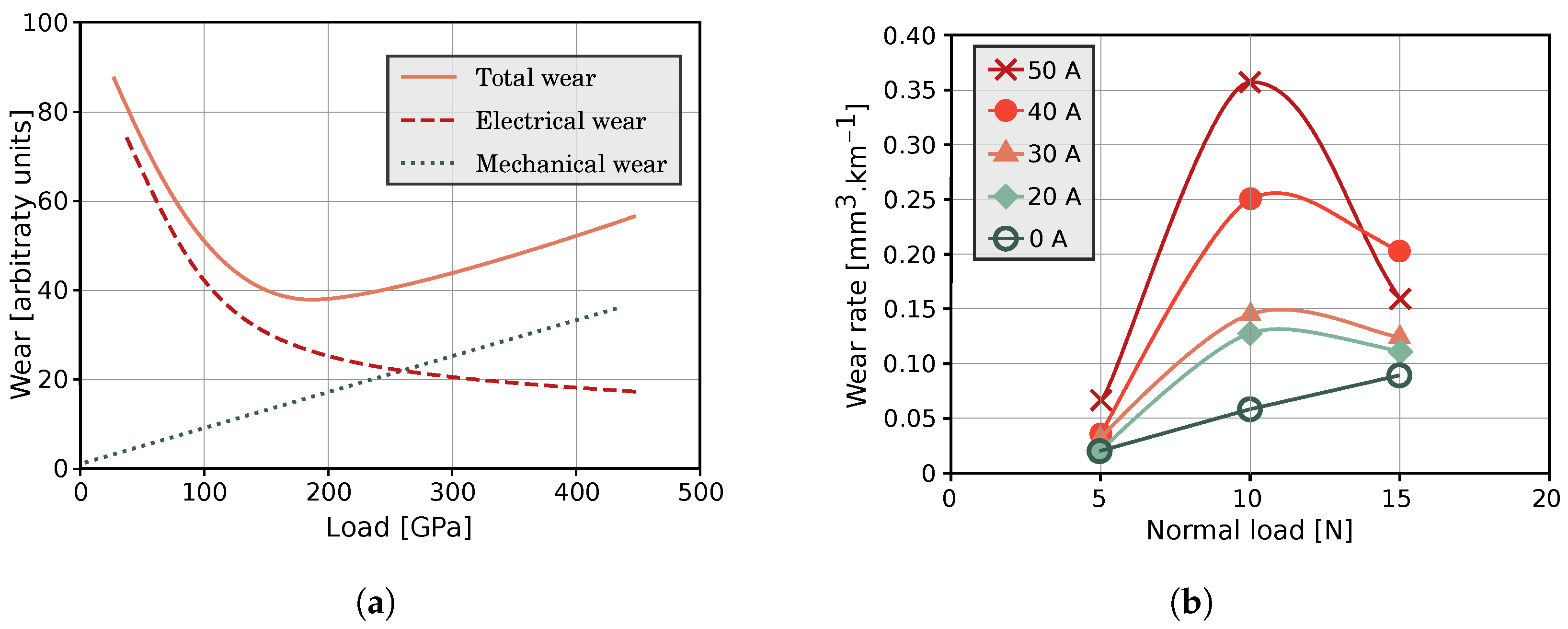
3.3.1. Impact of Normal Load on Mechanical Wear Versus Electrical Wear
3.3.2. Parameters Related to the Normal Load
- Periodic fluctuations: It is known that the contact force fluctuates due to the geometry of the catenary [63,64]. Zhang Y. et al. [29] observed that a periodic fluctuation of the normal load also influences the current carrying stability, its efficiency, and the arcing rate. In this work, the normal load is modulated in frequency f and amplitude B and the results obtained have shown that the arcing rate increases when f and B increase [18]. Model, force fluctuation, span length, preload, and speed. Strip spacing, friction coefficient, and lift force. More spacing between strips, more lift force, and friction coefficient.
- The stiffness of the contact: A pantograph is a lumped-mass system of three levels. The value of the stiffness and the lump have a direct impact on the contact behaviour and the behaviour of the contact force [63,64]. Stiffness has been experimentally studied by Ding T. et al. [65]. They observed that stiffness has a significant effect on the friction coefficient and the wear rate. The latter increases at the extreme stiffness values: slightly with low stiffness and sharply when stiffness becomes too high, reaching a maximum when the contact is strongly rigid. These variations are explained by vibration, which leads to arc discharge.The impact of stiffness is different depending on the sliding speed and the current. Nonetheless, it has been found that an optimal stiffness value leads to wear minimisation.
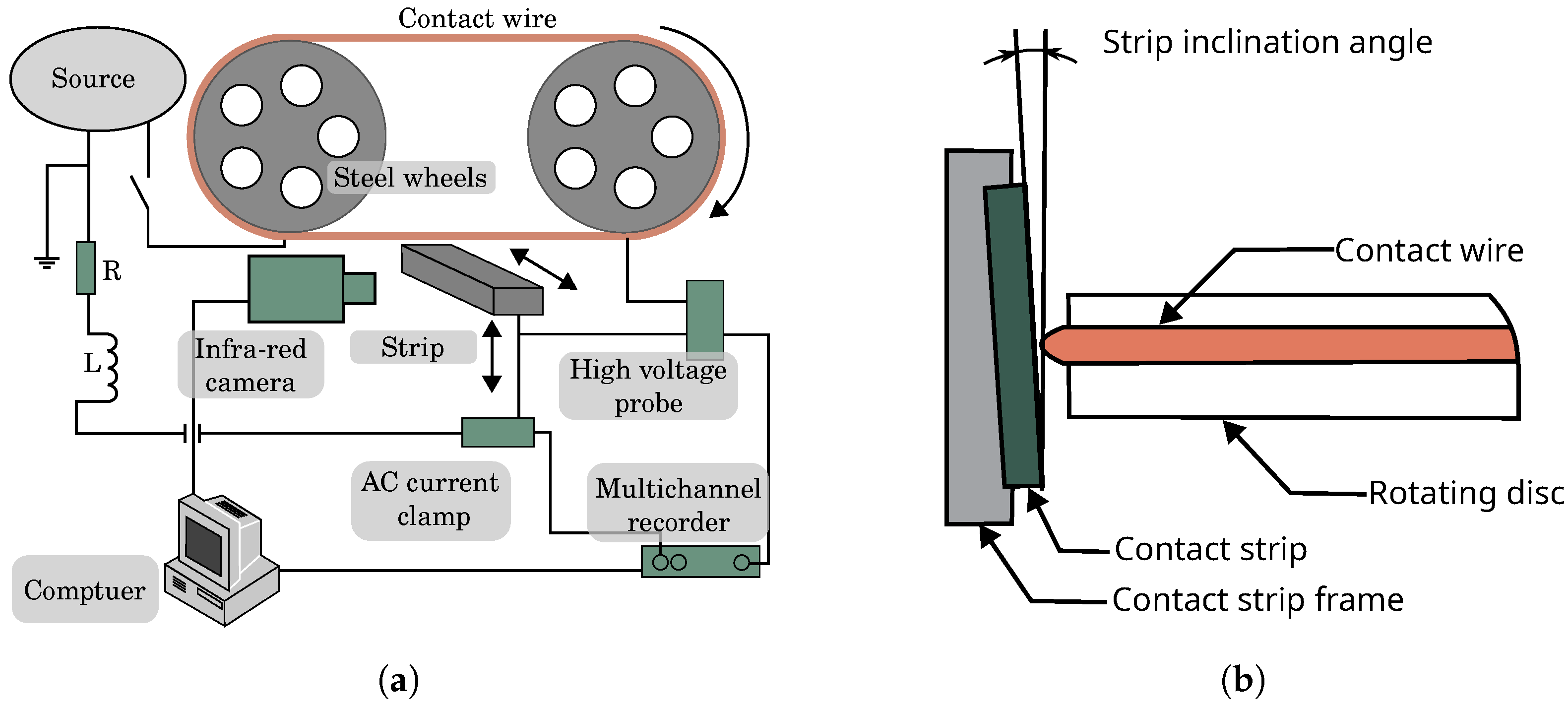
- Contact area: By setting an inclination angle between the contact strip and the wire, Chen G. et al. [34] changed the contact area and thus the contact pressure between the strip and the wire. The increase in the contact pressure results in decreasing the friction coefficient and the temperature of the contact. It also reduces the wear rate and the scaled accumulated energy (see Equation (2)), especially at low normal load (30 N).
3.4. Sliding Speed
3.4.1. Slip Ring
3.4.2. Pantograph–Catenary Link
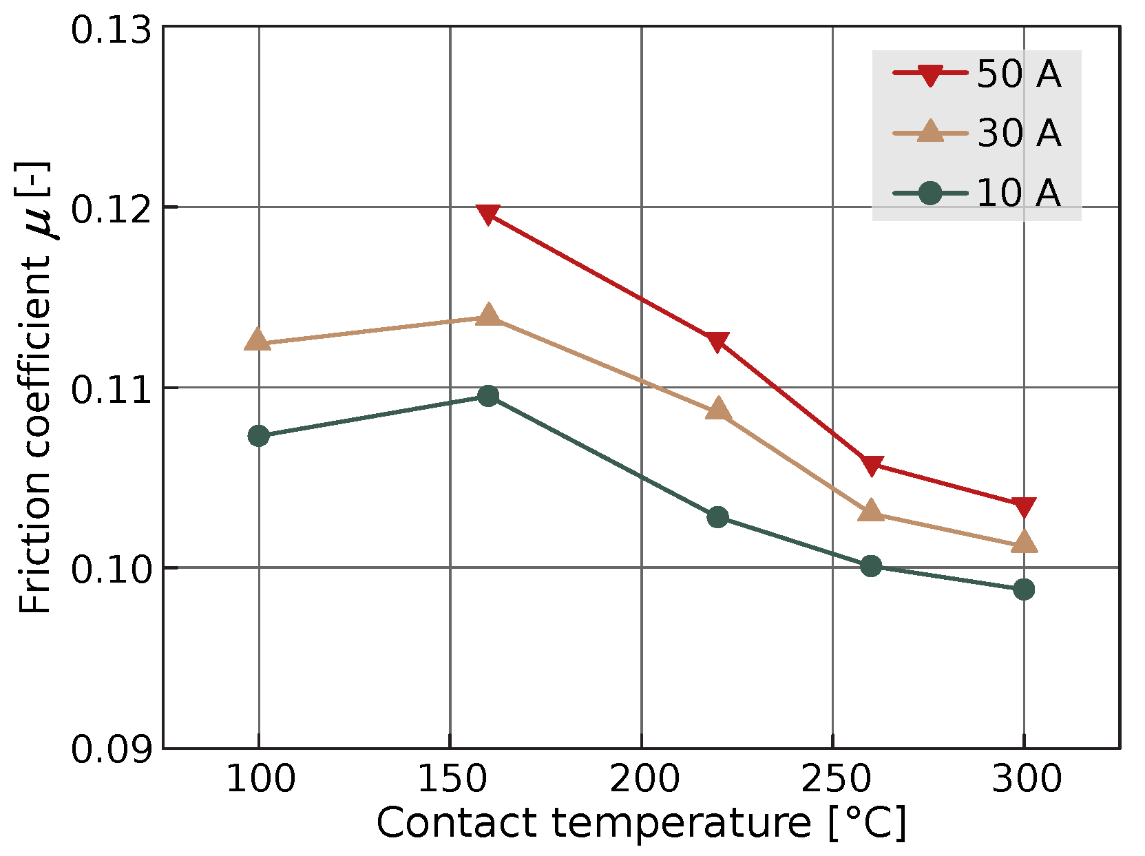
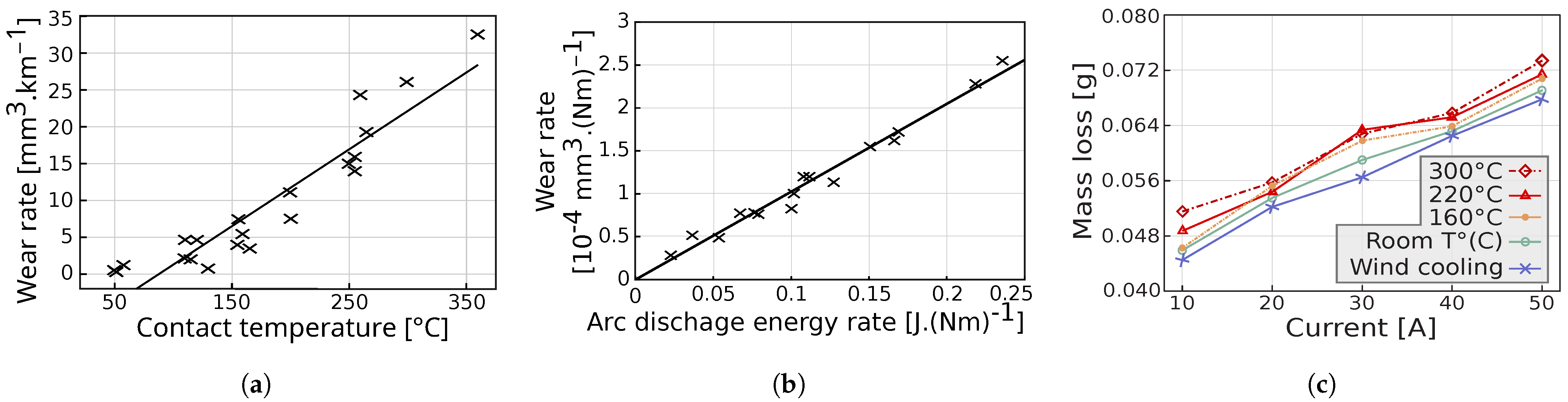
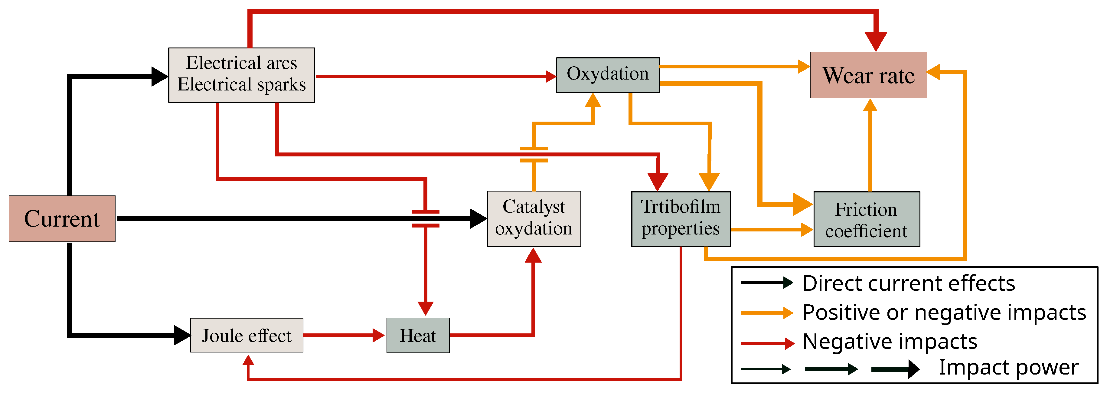
3.5. Current
- (1)
- The oxidation catalysis of the contact surface impacts the friction coefficient, the wear rate, and the contact temperature;
- (2)
- The Joule effect produces heat due to high electrical contact resistance;
- (3)
- Sparks and arcs discharge when contact loss occurs, increasing the temperature and wear rate.
3.5.1. Catalysis Oxidation
3.5.2. Heat by Joule Effect
3.5.3. Arcing
- (1)
- (2)
- Melted copper asperities can solidify directly close to the contact. The resulting particle makes grooves and ridges on the friction track due to the tangential force, making the surface rougher. This also enhances abrasive wear rate [74];
- (3)
- The exudate copper from impregnated carbon can form a metallic film [74];
- (4)
- After arcing, some cracks can be observed on the surface. This could be due to the non-homogenous thermal conduction properties of the material, leading to thermal strain between the carbon substrate and the impregnated copper. Crack nucleation can then occur through contact fatigue [74].
3.5.4. Direction of Current Flow
3.5.5. Wear Rate
- •
- When increasing the normal load, a downward trend of the wear rate is most often observed. Nevertheless, this trend is controversial among scholars. Furthermore, the stiffness of the strip plays a key role in vibration and arc occurrence, yet it has been discussed very little.
- •
- The causes of wear are also being discussed and processes are still not well understood when the current is flowing. Electric arc and Joule effects are the main factors in the wear of electric sliding contact. Yet, from a chemical standpoint, the role of current flowing through copper and graphite has not been much studied.
- •
- Through the articles mentioned and their results, specific wear rate and wear rate are both used to quantify wear properties. Results show strong differences from one another.
- •
- The material used as a strip of course plays a key role in the wear mechanism and the behaviour of the electrical sliding contact. As a matter of fact, the manufacturing process, impregnated rate, impregnated process, hardness, and electrical resistance have been said to change the wear rate, the friction coefficient, and contact temperature increase. Materials also have displayed different behaviours when changing the normal load, the sliding speed, and the current flow.
4. Conclusions
Author Contributions
Funding
Acknowledgments
Conflicts of Interest
Abbreviations
| SEC | Sliding electrical contacts |
| SEM | Scanning electron microscopy |
| EDS | Energy dispersive spectroscopy |
| CCTB | Current collection test bench |
| PCL | Pantograph–catenary link |
References
- Delcey, N.; Baucour, P.; Chamagne, D.; Wimmer, G.; Bucca, G.; Bruyere, N.; Bouger, O.; Auditeau, G.; Bausseron, T. Analysis of the thermal variations in a moving pantograph strip using an electro-thermal simulation tool and validating by experimental tests. Proc. Inst. Mech. Eng. Part F J. Rail Rapid Transit 2019, 234, 859–868. [Google Scholar] [CrossRef]
- Bares, J.; Argibay, N.; Mauntler, N.; Dudder, G.; Perry, S.; Bourne, G.; Sawyer, W. High current density copper-on-copper sliding electrical contacts at low sliding velocities. Wear 2009, 267, 417–424. [Google Scholar] [CrossRef]
- He, D.H.; Manory, R. A novel electrical contact material with improved self-lubrication for railway current collectors. Wear 2001, 249, 626–636. [Google Scholar] [CrossRef]
- Ordoñez, M.; Farias, M.; Descartes, S.; Machado, I.; Souza, R. Tribofilm formation during dry sliding of graphite- and MoS2- based composites obtained by spark plasma sintering. Tribol. Int. 2021, 160, 107035. [Google Scholar] [CrossRef]
- Bausseron, T.; Baucour, P.; Glises, R.; Verschelde, S.; Chamagne, D. Experimental study and modelling of overheating of electrical catenary-pantograph interface for trains supplied with power in station. Eur. Phys. J. Appl. Phys. 2015, 70, 30901. [Google Scholar] [CrossRef]
- Grandin, M.; Wiklund, U. Wear phenomena and tribofilm formation of copper/copper-graphite sliding electrical contact materials. Wear 2018, 398-399, 227–235. [Google Scholar] [CrossRef]
- Hu, Z.; Chen, Z.; Xia, J. Study on surface film in the wear of electrographite brushes against copper commutators for variable current and humidity. Wear 2008, 264, 11–17. [Google Scholar] [CrossRef]
- Zhang, Y.; Li, C.; Pang, X.; Song, C.; Ni, F.; Zhang, Y. Evolution processes of the tribological properties in pantograph/catenary system affected by dynamic contact force during current-carrying sliding. Wear 2021, 477, 203809. [Google Scholar] [CrossRef]
- Ding, T.; Chen, G.; Bu, J.; Zhang, W. Effect of temperature and arc discharge on friction and wear behaviours of carbon strip/copper contact wire in pantograph-catenary systems. Wear 2011, 271, 1629–1636. [Google Scholar] [CrossRef]
- Derosa, S.; Nåvik, P.; Collina, A.; Bucca, G.; Rønnquist, A. Contact point lateral speed effects on contact strip wear in pantograph-catenary interaction for railway operations under 15 kV 16.67 Hz AC systems. Wear 2021, 486-487, 204103. [Google Scholar] [CrossRef]
- Bucca, G.; Collina, A. Electromechanical interaction between carbon-based pantograph strip and copper contact wire: A heuristic wear model. Tribol. Int. 2015, 92, 47–56. [Google Scholar] [CrossRef] [Green Version]
- Mei, G.; Song, Y. Effect of Overhead Contact Line Pre-Sag on the Interaction Performance with a Pantograph in Electrified Railways. Energies 2022, 15, 6875. [Google Scholar] [CrossRef]
- Song, Y.; Zhang, M.; Øiseth, O.; Rønnquist, A. Wind deflection analysis of railway catenary under crosswind based on nonlinear finite element model and wind tunnel test. Mech. Mach. Theory 2022, 168, 104608. [Google Scholar] [CrossRef]
- Materra, J.P. Développement d’un outil de modélisation électrothermique d’une caténaire du domaine ferroviaire. Ph.D. Thesis, Université de Franche-Comte, Besançon, France, 2010. [Google Scholar]
- Song, Y.; Liu, Z.; Wang, H.; Lu, X.; Zhang, J. Nonlinear analysis of wind-induced vibration of high-speed railway catenary and its influence on pantograph–catenary interaction. Veh. Syst. Dyn. 2016, 54, 723–747. [Google Scholar] [CrossRef]
- Song, Y.; Liu, Z.; Rxnnquist, A.; Navik, P.; Liu, Z. Contact Wire Irregularity Stochastics and Effect on High-speed Railway Pantograph-Catenary Interactions. IEEE Trans. Instrum. Meas. 2020, 69, 8196–8206. [Google Scholar] [CrossRef]
- Song, Y.; Antunes, P.; Pombo, J.; Liu, Z. A methodology to study high-speed pantograph-catenary interaction with realistic contact wire irregularities. Mech. Mach. Theory 2020, 152, 103940. [Google Scholar] [CrossRef]
- Simarro, M.; Castillo, J.J.; Cabrera, J.A.; Postigo, S. Evaluation of the influence of the speed, preload and span length on the contact forces in the interaction between the pantograph and the overhead conductor rail. Eng. Struct. 2021, 243, 112678. [Google Scholar] [CrossRef]
- Pappalardo, C.M.; Patel, M.D.; Tinsley, B.; Shabana, A.A. Contact force control in multibody pantograph/catenary systems. Proc. Inst. Mech. Eng. Part K J. Multi-Body Dyn. 2016, 230, 307–328. [Google Scholar] [CrossRef]
- Daocharoenporn, S.; Mongkolwongrojn, M.; Kulkarni, S.; Shabana, A.A. Prediction of the Pantograph/Catenary Wear Using Nonlinear Multibody System Dynamic Algorithms. J. Tribol. 2019, 141, 051603. [Google Scholar] [CrossRef]
- Jia, S.; Liu, P.; Ren, F.; Tian, B.; Zheng, M.; Zhou, G. Wear behavior of Cu—Ag—Cr alloy wire under electrical sliding. Mater. Sci. Eng. A 2005, 398, 262–267. [Google Scholar] [CrossRef]
- Dai, Z.; Li, T.; Deng, J.; Zhou, N.; Zhang, W. Effect of the strip spacing on the aerodynamic performance of a high-speed double-strip pantograph. Veh. Syst. Dyn. 2021, 60, 3358–3374. [Google Scholar] [CrossRef]
- Dai, Z.; Li, T.; Zhou, N.; Zhang, J.; Zhang, W. Numerical simulation and optimization of aerodynamic uplift force of a high-speed pantograph. Railw. Eng. Sci. 2022, 30, 117–128. [Google Scholar] [CrossRef]
- Carnevale, M.; Facchinetti, A.; Maggiori, L.; Rocchi, D. Computational fluid dynamics as a means of assessing the influence of aerodynamic forces on the mean contact force acting on a pantograph. Proc. Inst. Mech. Eng. Part F J. Rail Rapid Transit 2016, 230, 1698–1713. [Google Scholar] [CrossRef]
- Yang, Z.; Xu, P.; Wei, W.; Gao, G.; Zhou, N.; Wu, G. Influence of the Crosswind on the Pantograph Arcing Dynamics. IEEE Trans. Plasma Sci. 2020, 48, 2822–2830. [Google Scholar] [CrossRef]
- Derosa, S.; Nåvik, P.; Collina, A.; Bucca, G.; Rønnquist, A. A heuristic wear model for the contact strip and contact wire in pantograph-catenary interaction for railway operations under 15 kV 16.67 Hz AC systems. Wear 2020, 456-457, 203401. [Google Scholar] [CrossRef]
- Bucca, G.; Collina, A. A procedure for the wear prediction of collector strip and contact wire in pantograph-catenary system. Wear 2009, 266, 46–59. [Google Scholar] [CrossRef]
- Lin, Y.; Wu, M.; Ju, X.; Lin, W.; Ma, D.; Jin, L. Finite Element Simulation Study on Wear under Pantograph-Catenary System with Electric Current. In Proceedings of the 2020 IEEE International Conference on High Voltage Engineering and Application (ICHVE), Beijing, China, 6–10 September 2020. [Google Scholar] [CrossRef]
- Zhang, Y.; Zhang, Y.; Song, C. Arc Discharges of a Pure Carbon Strip Affected by Dynamic Contact Force during Current-Carrying Sliding. Materials 2018, 11, 796. [Google Scholar] [CrossRef] [Green Version]
- Yang, Z.; Zhang, Y.; Zhao, F.; Shangguan, B. Dynamic variation of arc discharge during current-carrying sliding and its effect on directional erosion. Tribol. Int. 2016, 94, 71–76. [Google Scholar] [CrossRef]
- Yang, Z.; Ge, Y.; Zhang, X.; Shangguan, B.; Zhang, Y.; Zhang, J. Effect of Carbon Content on Friction and Wear Properties of Copper Matrix Composites at High Speed Current-Carrying. Materials 2019, 12, 2881. [Google Scholar] [CrossRef] [PubMed] [Green Version]
- Wu, G.; Wei, W.; Gao, G.; Wu, J.; Zhou, Y. Evolution of the electrical contact of dynamic pantograph-catenary system. J. Mod. Transp. 2016, 24, 132–138. [Google Scholar] [CrossRef] [Green Version]
- Wu, G.; Wu, J.; Wei, W.; Zhou, Y.; Yang, Z.; Gao, G. Characteristics of the Sliding Electric Contact of Pantograph/Contact Wire Systems in Electric Railways. Energies 2017, 11, 17. [Google Scholar] [CrossRef] [Green Version]
- Chen, G.; Yang, H.; Zhang, W.; Lu, Y.; Zhang, S.; Zhou, Z. Effect of the strip inclination angle on the friction and wear behavior of contact strip against contact wire with electric current. Proc. Inst. Mech. Eng. Part J J. Eng. Tribol. 2013, 227, 1406–1417. [Google Scholar] [CrossRef]
- Chen, G.X.; Hu, Y.; Dong, B.J.; Yang, H.J.; Gao, G.Q.; Wu, G.N.; Zhang, W.H.; Zhou, Z.R. Experimental study on the temperature of the contact strip in sliding electric contact. Eng. Tribol. 2017, 231, 1–8. [Google Scholar] [CrossRef]
- Mei, G. Tribological performance of rigid overhead lines against pantograph sliders under DC passage. Tribol. Int. 2020, 151, 106538. [Google Scholar] [CrossRef]
- Bucca, G.; Collina, A.; Manigrasso, R.; Mapelli, F.; Tarsitano, D. Analysis of electrical interferences related to the current collection quality in pantograph–catenary interaction. J. Rail Rapid Transit 2011, 225, 483–499. [Google Scholar] [CrossRef]
- Bucca, G.; Collina, A.; Tanzi, E. Experimental analysis of the influence of the electrical arc on the wear rate of contact strip and contact wire in a.c. system. In Advances in Italian Mechanism Science; Springer: Berlin/Heidelberg, Germany, 2016. [Google Scholar]
- Benfoughal, A.; Bouchoucha, A.; Mouadji, Y. Effect of electrical current on friction and wear behavior of copper against graphite for low sliding speeds. U.P.B. Sci. Bull. Ser. D Mech. Eng. 2018, 80, 117–130. [Google Scholar]
- Poljanec, D.; Kalin, M.; Kumar, L. Influence of contact parameters on the tribological behaviour of various graphite/graphite sliding electrical contacts. Wear 2018, 406–407, 75–83. [Google Scholar] [CrossRef]
- Shin, W.G.; Lee, S.H. An analysis of the main factors on the wear of brushes for automotive small brush-type DC motor. J. Mech. Sci. Technol. 2010, 24, 37–41. [Google Scholar] [CrossRef]
- Turel, A.; Slavič, J.; Boltežar, M. Electrical contact resistance and wear of a dynamically excited metal–graphite brush. Adv. Mech. Eng. 2017, 9, 1687814017694801. [Google Scholar] [CrossRef] [Green Version]
- Zhao, H.; Feng, Y.; Zhou, Z.; Qian, G.; Zhang, J.; Huang, X.; Zhang, X. Effect of electrical current density, apparent contact pressure, and sliding velocity on the electrical sliding wear behavior of Cu—Ti3AlC2 composites. Wear 2020, 444-445, 203156. [Google Scholar] [CrossRef]
- Wu, G.; Zhou, Y.; Gao, G.; Wu, J.; Wei, W. Arc Erosion Characteristics of Cu-Impregnated Carbon Materials Used for Current Collection in High-Speed Railways. IEEE Trans. Compon. Packag. Manuf. 2018, 8, 1014–1023. [Google Scholar] [CrossRef]
- Midya, S.; Bormann, D.; Larsson, A.; Schutte, T.; Thottappillil, R. Understanding pantograph arcing in electrified railways—Influence of various parameters. In Proceedings of the 2008 IEEE International Symposium on Electromagnetic Compatibility, Hamburg, Germany, 8–12 September 2008. [Google Scholar] [CrossRef]
- Midya, S.; Bormann, D.; Schutte, T.; Thottappillil, R. Pantograph Arcing in Electrified Railways—Mechanism and Influence of Various Parameters—Part I: With DC Traction Power Supply. IEEE Trans. Power Deliv. 2009, 24, 1931–1939. [Google Scholar] [CrossRef]
- Liu, X.; Hu, M.; Li, Z.; Zhou, C.; Xiao, Q.; Yang, W.; Chen, D. Effect of copper contents on the current-carrying wear properties of carbon brush under different temperatures conditions. J. Mater. Res. Technol. 2021, 15, 3110–3121. [Google Scholar] [CrossRef]
- Liu, R.; Cheng, K.; Chen, J.; Xiong, X.; Lin, X. Friction and wear properties of high temperature and low temperature sintered copper-graphite brushes at different ambient temperatures. J. Mater. Res. Technol. 2020, 9, 7288–7296. [Google Scholar] [CrossRef]
- Qian, G.; Feng, Y.; Li, B.; Huang, S.; Liu, H.; Ding, K. Effect of electrical current on the tribological behavior of the Cu-WS2-G composites in air and vacuum. Chin. J. Mech. Eng. 2013, 26, 384–392. [Google Scholar] [CrossRef]
- Senouci, A.; Zaidi, H.; Frene, J.; Bouchoucha, A.; Paulmier, D. Damage of surfaces in sliding electrical contact copper/steel. Appl. Surf. Sci. 1999, 144–145, 287–291. [Google Scholar] [CrossRef]
- Cantürk, S.B.; Kováčik, J. Review of Recent Development in Copper/Carbon Composites Prepared by Infiltration Technique. Energies 2022, 15, 5227. [Google Scholar] [CrossRef]
- Cheng, K.; Liu, R.; Xiong, X.; Lin, X.; Chen, J. The Effect of Sintering Temperature on the Microstructures and Properties of Resin-Bonded Copper—Graphite Brush Materials. Tribol. Lett. 2019, 67, 77. [Google Scholar] [CrossRef]
- Mańka, A.; Hełka, A.; Ćwiek, J. The Influence of Pantograph Carbon—Metal Composite Slider Thermal Properties on the Railroad Wire Temperature. Energies 2021, 14, 7940. [Google Scholar] [CrossRef]
- Holm, R. Electric Contacts—Theory and Application, 3rd ed.; Springer: Berlin/Heidelberg, Germany, 1967. [Google Scholar] [CrossRef] [Green Version]
- Chen, G.X.; Li, F.X.; Dong, L.; Zhu, M.H.; Zhou, Z.R. Friction and wear behaviour of stainless steel rubbing against copper-impregnated metallized carbon. Tribol. Int. 2009, 42, 934–939. [Google Scholar] [CrossRef]
- Ding, T.; Xuan, W.; He, Q.; Wu, H.; Xiong, W. Study on Friction and Wear Properties of Pantograph Strip/Copper Contact Wire for High-Speed Train. Open Mech. Eng. J. 2014, 8, 125–128. [Google Scholar] [CrossRef] [Green Version]
- Delcey, N. Modélisation électro-thermique d’un pantographe pour un train en mouvement. Ph.D. Thesis, Université Bourgogne-Franche Comté, Besançon, France, 2018. [Google Scholar]
- Mei, G. Impact of voltage on the electric sliding tribological properties of current collectors against overhead lines. Wear 2021, 474–475, 203868. [Google Scholar] [CrossRef]
- Wang, W.; Dong, A.; Wu, G.; Gao, G.; Zhou, L.; Wang, B.; Cui, Y.; Liu, D.; Li, D.; Li, T. Study on Characterization of Electrical Contact Between Pantograph and Catenary. In Proceedings of the IEEE 57th Holm Conference on Electrical Contacts (Holm), Minneapolis, MN, USA, 11–14 September 2011. [Google Scholar]
- Braunovic, M.; Myshkin, N.K.; Konchits, V.V. Electrical Contacts; Taylor & Francis Ltd.: Abingdon-on-Thames, UK, 2017. [Google Scholar]
- Wang, Y.; Li, J.; Yan, Y.; Qiao, L. Effect of electrical current on tribological behavior of copper-impregnated metallized carbon against a Cu-Cr-Zr alloy. Tribol. Int. 2012, 50, 26–34. [Google Scholar] [CrossRef]
- Zhao, H.; Barber, G.; Liu, J. Friction and wear in high speed sliding with and without electrical current. Wear 2001, 249, 409–414. [Google Scholar] [CrossRef]
- Vo-Van, O.; Massat, J.P.; Laurent, C.; Balmes, E. Introduction of variability into pantograph-catenary dynamic simulations. Veh. Syst. Dyn. 2014, 52, 1254–1269. [Google Scholar] [CrossRef] [Green Version]
- Pombo, J.; Ambrósio, J. Influence of pantograph suspension characteristics on the contact quality with the catenary for high speed trains. Comput. Struct. 2012, 110–111, 32–42. [Google Scholar] [CrossRef]
- Ding, T.; Chen, G.; Zhu, M.; Zhang, W.; Zhou, Z. Influence of the spring stiffness on friction and wear behaviours of stainless steel/copper-impregnated metallized carbon couple with electrical current. Wear 2009, 267, 1080–1086. [Google Scholar] [CrossRef]
- Ratovoson, P.L. Caractérisation expérimentale d’un arc impulsionnel. Ph.D. Thesis, Université Toulouse III Paul Sabatier, Toulouse, France, 2015. [Google Scholar]
- Ding, T.; Chen, G.X.; Wang, X.; Zhu, M.H.; Zhang, W.H.; Zhou, W.X. Friction and wear behavior of pure carbon strip sliding against copper contact wire under AC passage at high speeds. Tribol. Int. 2011, 44, 437–444. [Google Scholar] [CrossRef]
- Kubota, Y. Relationship between Wear Profile of Pantograph Contact Strip and Arc Discharge Energy Distribution. In Proceedings of the 2018 IEEE Holm Conference on Electrical Contacts, Albuquerque, NM, USA, 14–18 October 2018. [Google Scholar] [CrossRef]
- Csapo, E.; Zaidi, H.; Paulmier, D.; Kadiri, E.; Bouchoucha, A.; Robert, F. Influence of the electrical current on the graphite surface in an electrical sliding contact. Surf. Coat. Technol. 1995, 76-77, 421–424. [Google Scholar] [CrossRef]
- Bouchoucha, A.; Chekroud, S.; Paulmier, D. Influence of the electrical sliding speed on friction and wear processes in an electrical contact copper–stainless steel. Appl. Surf. Sci. 2004, 223, 330–342. [Google Scholar] [CrossRef]
- Grandin, M.; Wiklund, U. Friction, wear and tribofilm formation on electrical contact materials in reciprocating sliding against silver-graphite. Wear 2013, 302, 1481–1491. [Google Scholar] [CrossRef]
- Jin, M.; Hu, M.; Li, H.; Yang, Y.; Liu, W.; Fang, Q.; Liu, S. Experimental Study on the Transient Disturbance Characteristics and Influence Factors of Pantograph-Catenary Discharge. Energies 2022, 15, 5959. [Google Scholar] [CrossRef]
- Kubo, S.; Kato, K. Effect of arc discharge on wear rate of Cu-impregnated carbon strip in unlubricated sliding against Cu trolley under electric current. Wear 1997, 216, 172–178. [Google Scholar] [CrossRef]
- Kubota, Y.; Nagasaka, S.; Miyauchi, T.; Yamashita, C.; Kakishima, H. Sliding wear behavior of copper alloy impregnated C/C composites under an electrical current. Wear 2013, 302, 1492–1498. [Google Scholar] [CrossRef]
- Senouci, A.; Frene, J.; Zaidi, H. Wear mechanism in graphite–copper electrical sliding contact. Wear 1999, 225, 949–953. [Google Scholar] [CrossRef]
- El Mansori, M.; Paulmier, D.; Ginsztler, J.; Horvath, M. Lubrication mechanisms of a sliding contact by simultaneous action of electric current and magnetic field. Wear 1999, 225-229, 1011–1016. [Google Scholar] [CrossRef]
- Bouchoucha, A.; Zaidi, H.; Kadiri, E.; Paulmier, D. Influence of electric fields on the tribological behaviour of electrodynamical copper/steel contacts. Wear 1997, 203-204, 434–441. [Google Scholar] [CrossRef]
- Hounkponou, E.; Nery, H.; Paulmier, D.; Bouchoucha, A.; Zaidi, H. Tribological behaviour of graphite/graphite and graphite/copper couples in sliding electrical contact: Influence on the contact electric field on the surface passivation. Appl. Surf. Sci. 1993, 70–71, 176–179. [Google Scholar] [CrossRef]
- Chapteuil, E.; Renouf, M.; Zeng, C.; Berthier, Y. Influence of Copper/Graphite Properties on the Tribological and Electrical Behavior of Copper-Graphite Third Body Layer. Lubricants 2018, 6, 109. [Google Scholar] [CrossRef] [Green Version]
- Mei, G.; Fu, W.; Chen, G.; Zhang, W. Effect of high-density current on the wear of carbon sliders against Cu-Ag wires. Wear 2020, 452-453, 203275. [Google Scholar] [CrossRef]
- Kubo, S.; Kato, K. Effect of arc discharge on the wear rate and wear mode transition of a copper-impregnated metallized carbon contact strip sliding against a copper disk. Tribol. Int. 1999, 32, 367–378. [Google Scholar] [CrossRef]
- Wu, G.; Gao, G.; Wei, W.; Yang, Z. Friction and Wear of Pantograph and Catenary. In The Electrical Contact of the Pantograph-Catenary System; Springer: Singapore, 2019; pp. 71–107. [Google Scholar] [CrossRef]
- Lin, X.; Liu, R.; Chen, J.; Xiong, X.; Liao, N. Study on current-carrying friction and wear properties of copper-graphite brush material reinforced by organosilicon. J. Mater. Res. Technol. 2021, 12, 365–375. [Google Scholar] [CrossRef]
- Yang, H.; Wang, K.; Liu, Y.; Fu, L.; Cui, X.; Jiang, G.; Hu, B. The formation of the delamination wear of the pure carbon strip and its influence on the friction and wear properties of the pantograph and catenary system. Wear 2020, 454-455, 203343. [Google Scholar] [CrossRef]
- Yang, H.; Li, C.; Liu, Y.; Fu, L.; Jiang, G.; Cui, X.; Hu, B.; Wang, K. Study on the delamination wear and its influence on the conductivity of the carbon contact strip in pantograph-catenary system under high-speed current-carrying condition. Wear 2021, 477, 203823. [Google Scholar] [CrossRef]


| Pin on Disc Tribotester [29] | Pin on Disc Tribotester [30,31] | Ring Block Test Bench [32,33] | Ring Block Test Bench [34,35,36] | Ring Block CCTB [1,27,37,38] | |
|---|---|---|---|---|---|
| Speed | 28 m·s | 20 m·s | 8.4 m·s | 110 m·s | 60 m·s |
| Normal load | 70 N | 70 N | 80 N | 10–300 N | 60–110 N |
| Voltage Current * | 300 A(AC) 50 Hz | 100 A(AC) 125 Hz | 200 A(AC) | 400 A(AC) 100–3000 V; 700 A(DC) 15–180 V | 1400 A(DC) 500 A(AC) 16 Hz 350 A(AC) 50 Hz |
| Zigzag motion | None | None | Yes | Yes (0.3–3 Hz) | Yes |
| Arc detection | Photo diode | None | None | Hall effect current sensor | Contact voltage history |
| Temperature measurement | None | None | Infrared camera | Infrared camera | K-type Thermocouple |
| Wear measurement | None | Mass loss method | None | Volume loss distance | Instantaneous NWR mass difference |
| Friction measurement | None | Yes | None | Load cells | Load cells |
| Surface analysis | SEM, XPS 3D profiler | SEM, EDS density Hardness roughness | SEM, EDS | Digital camera SEM, EDS | None |
| Strip material | Pure carbon | Pure copper, Copper–graphite composites, Copper–graphite-coated, | Pure carbon | Pure carbon | Carbon, Carbon-impregnated Cu (20–30%) |
| Wire material | QCr0.5 chromium copper alloy | QCr0.5 chromium copper alloy | Copper–magnesium alloy | Copper–silver alloy | Pure copper |
| Particularity | Fluctuation of dynamic normal load | Study frictional behaviour, Study of current | Precise non-intrusive thermal measurement | Adjustable angle of strip | Full-scale experiments Use of different types of current |
| Low-Speed Test Bench [39] | Tribological Test Device [40] | Test Bench of Brushes for Automotive Small Brush-Type DC Motor [41] | In Situ Experimental Test Bench of Metal Graphite Brush [42] | Friction Wear Tester for Cu-TiAlC Brush [43] | |
|---|---|---|---|---|---|
| Speed | 0.02–0.5 m·s | 10 m·s | 15 m·s | 14 m·s | 15 m·s |
| Normal load | 5–30 N | 1.25–5 N | 1.5–2.5 N | 2.4 N | 1.25–7.5 N·cm |
| Current | 0–10 A | 0–8 A(DC) 4.3 A·cm | 5–20 A(DC) | 1–5 A(DC) 3.4–17 A·cm | 0–15 A·cm |
| Arc detection | None | None | None | None | None |
| Temperature measurement | K-type Thermocouple | K-type Thermocouple | T-type Thermocouple | T-type Thermocouple | None |
| Wear measurement | None | Measure with mass loss and distance | Measure with mass loss and distance | Measure with position difference before/after test | Calculated with mass loss |
| Friction measurement | 3D piezoelectric sensor | None | Yes | None | Power loss method |
| Mass loss measurement | Before/after test | Before/after test | Before/after test | None | Before/after test |
| Surface analysis | OM, SEM EDS, 3D SP | 3D optical microscope, SEM, white light inter- ferometry, 3D SP | None | Digital camera | SEM, 3D surface profiler Raman Spectroscopy |
| Brush material | Electrographite DE9000 | Hard carbon, electrographite, polymer-bonded, graphite | Copper–graphite brush | Metal graphite (40wt% Cu, 60wt% C) | Cu-30%TiAlC |
| Ring material | Pure copper (99.9%) | Hard carbon electrographite polymer-bonded graphite | Copper | Copper (SE-Cu F25) | Cu-5%Ag |
| Particularity | Study at low speed | Use three different types of carbon, repeatability of results, contact surface given | Anode and cathode studied apart | Adjustable T Adjustable HR | Study of homemade Cu-TiAlC composites |
| Process | Sintered Temperature [°C] | Metal [%] | Misc [%] | Hardness HR10-392] | Resistivity [µΩ·mm] | Opening Porosity | Flexual Strength [Mpa] |
|---|---|---|---|---|---|---|---|
| Dry powder mixed Compressed (150 Mpa) Sintered 6 h | 450 | 62 | 1.5 Sn 4 MoS2 4.5 Resin | 64.3 | 901 | 8 | 23.8 |
| 910 | 45.6 | 785 | 17.5 | 32.4 |
Disclaimer/Publisher’s Note: The statements, opinions and data contained in all publications are solely those of the individual author(s) and contributor(s) and not of MDPI and/or the editor(s). MDPI and/or the editor(s) disclaim responsibility for any injury to people or property resulting from any ideas, methods, instructions or products referred to in the content. |
© 2023 by the authors. Licensee MDPI, Basel, Switzerland. This article is an open access article distributed under the terms and conditions of the Creative Commons Attribution (CC BY) license (https://creativecommons.org/licenses/by/4.0/).
Share and Cite
Kziazyk, T.; Gavignet, E.; Cornuault, P.-H.; Baucour, P.; Chamagne, D. Review on Test Benches Studying Sliding Electrical Contact and Synthesis of Experimental Results. Energies 2023, 16, 1294. https://doi.org/10.3390/en16031294
Kziazyk T, Gavignet E, Cornuault P-H, Baucour P, Chamagne D. Review on Test Benches Studying Sliding Electrical Contact and Synthesis of Experimental Results. Energies. 2023; 16(3):1294. https://doi.org/10.3390/en16031294
Chicago/Turabian StyleKziazyk, Théo, Eric Gavignet, Pierre-Henri Cornuault, Philippe Baucour, and Didier Chamagne. 2023. "Review on Test Benches Studying Sliding Electrical Contact and Synthesis of Experimental Results" Energies 16, no. 3: 1294. https://doi.org/10.3390/en16031294