
Triboelectric Nanogenerator-Based Vibration Energy Harvester Using Bio-Inspired Microparticles and Mechanical Motion Amplification

 , , ,
, , ,
Abstract
1. Introduction
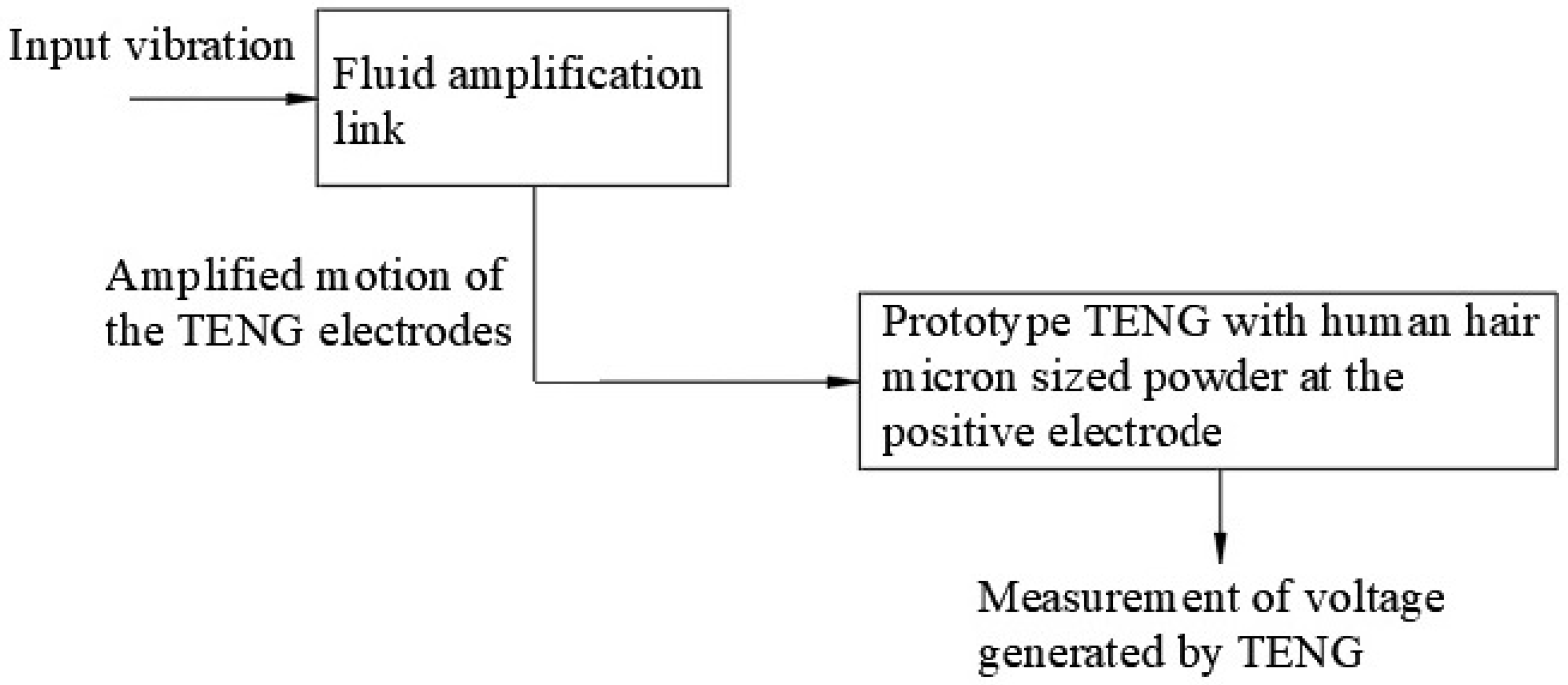
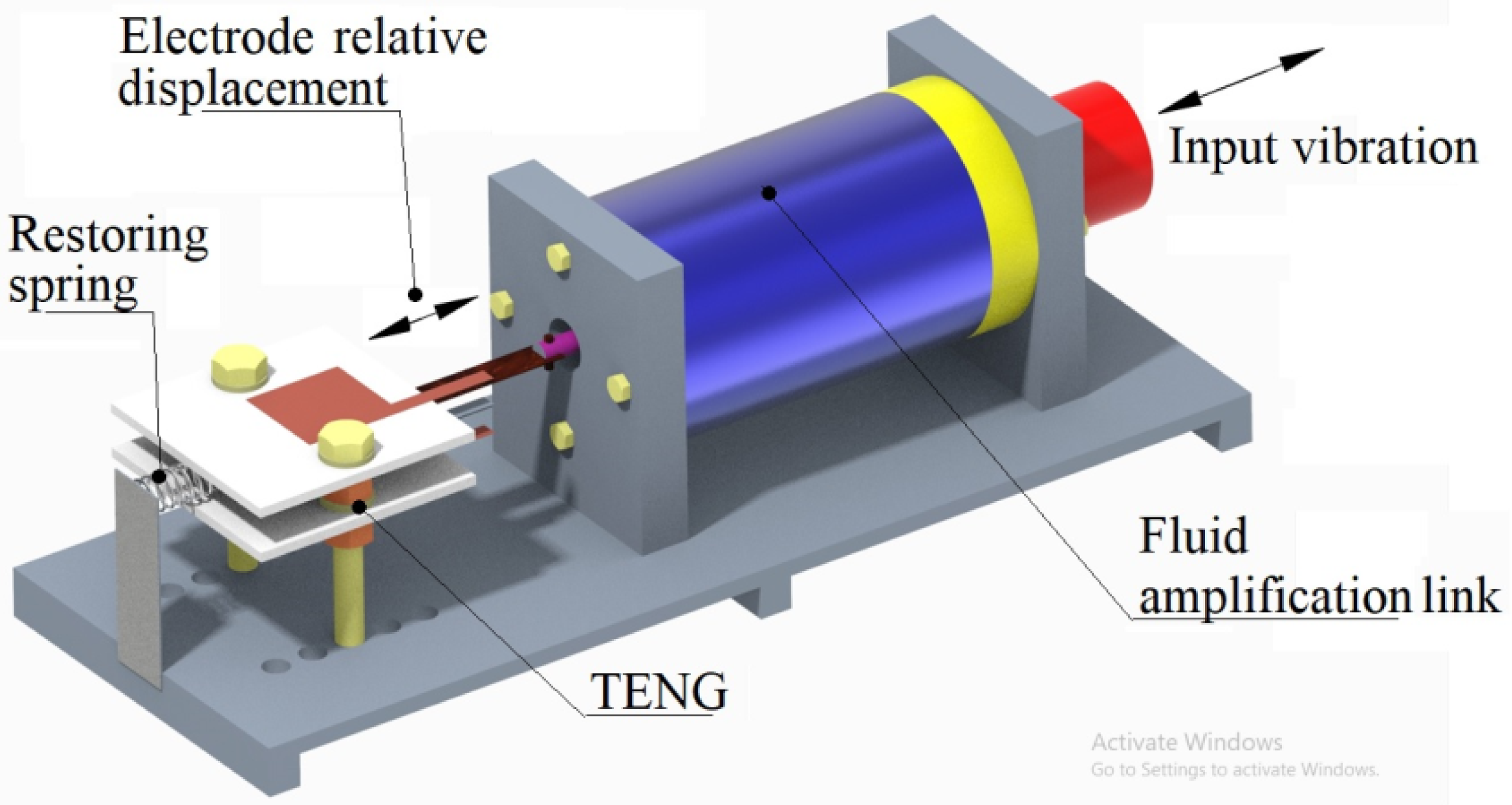
- In corporation of displacement amplification with the fluid link to ensure higher relative displacement of the TENG electrode, even if the input vibration amplitude is smaller. Absence of gears for motion amplification results in a robust and reliable construction.
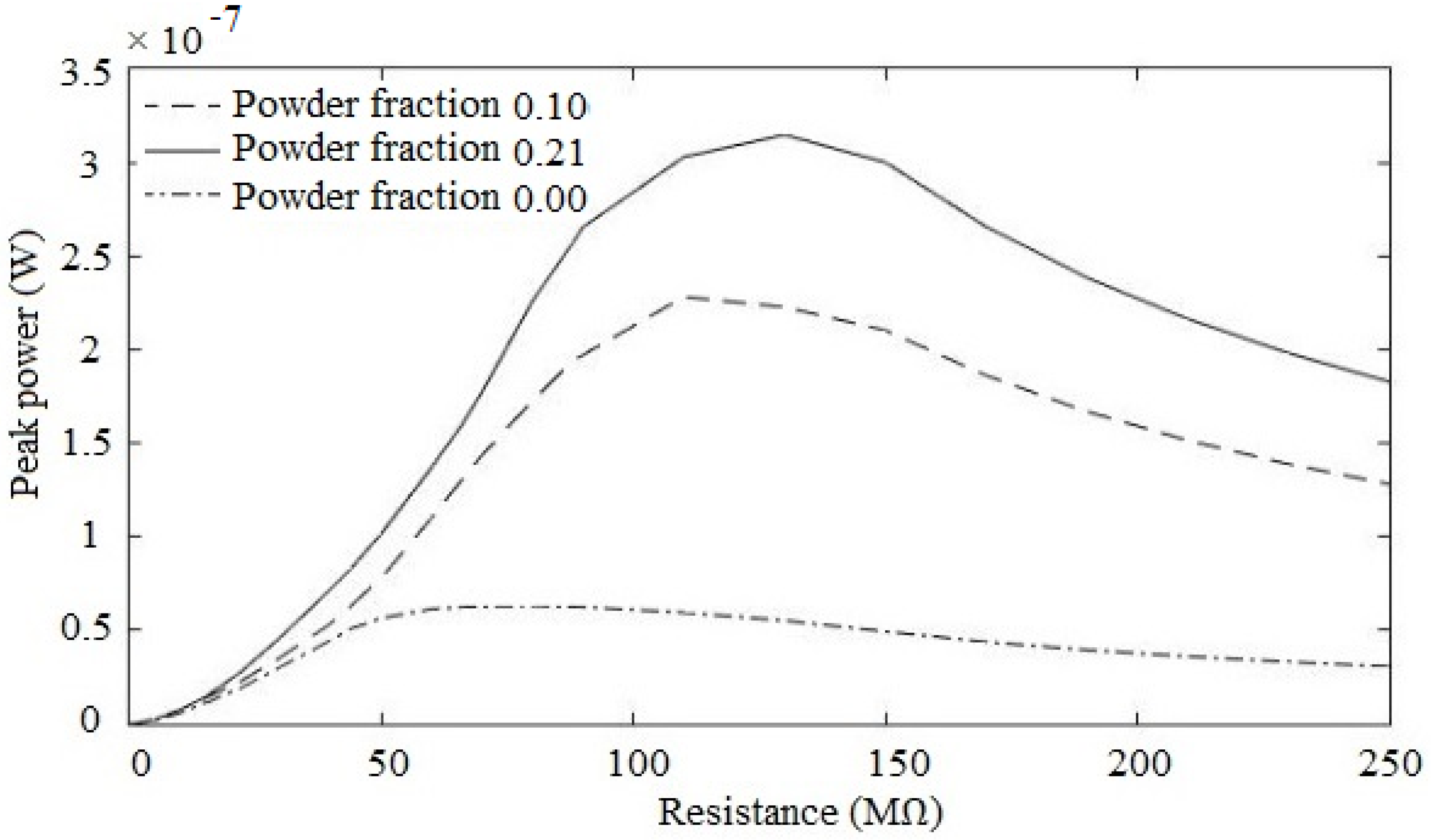
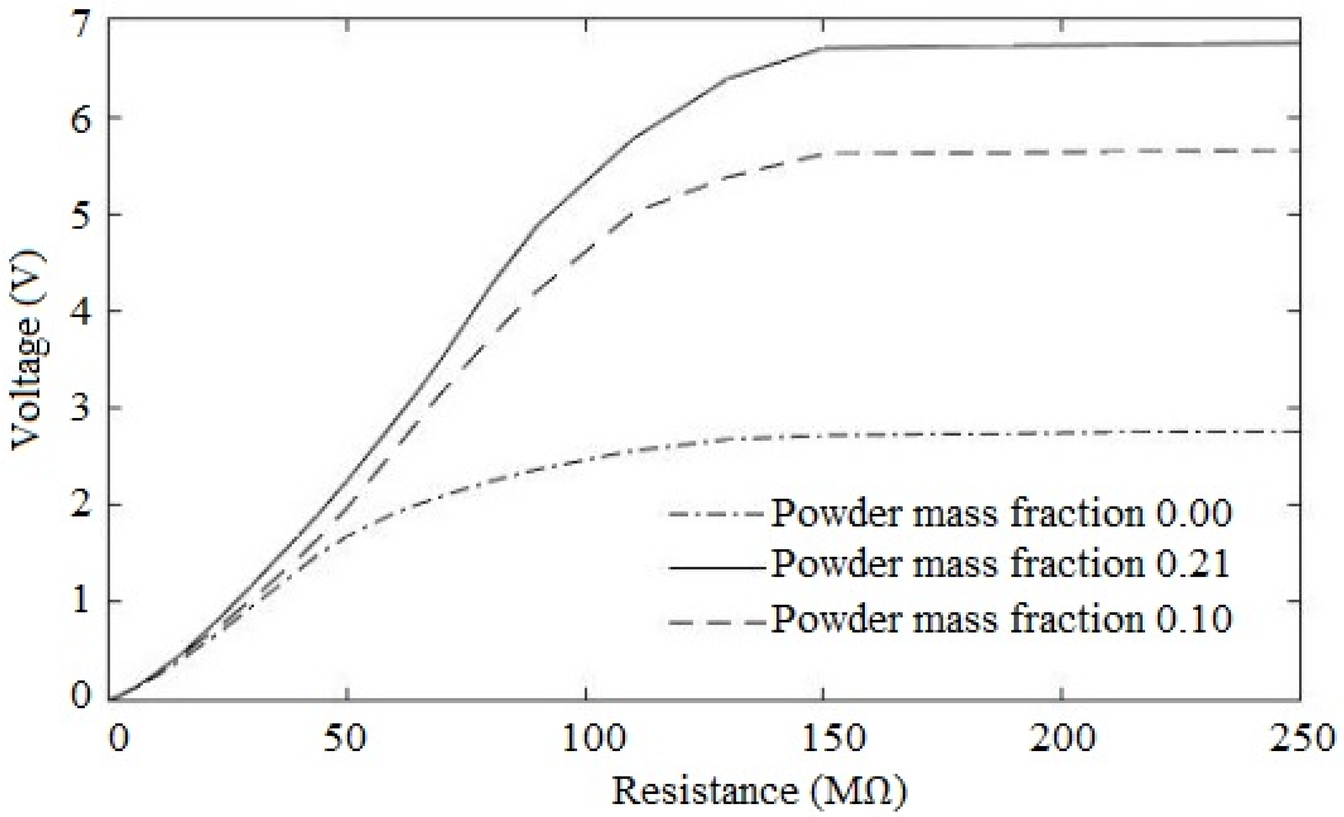
- Use of human hair powder with particle size lower than 25 µm to increase surface charge at the positive electrode to ensure peak power density of 0.262 mW/m2 and increase in the peak power of up to 403.7%.
- Detailed mathematical modeling supported with experimental validation.
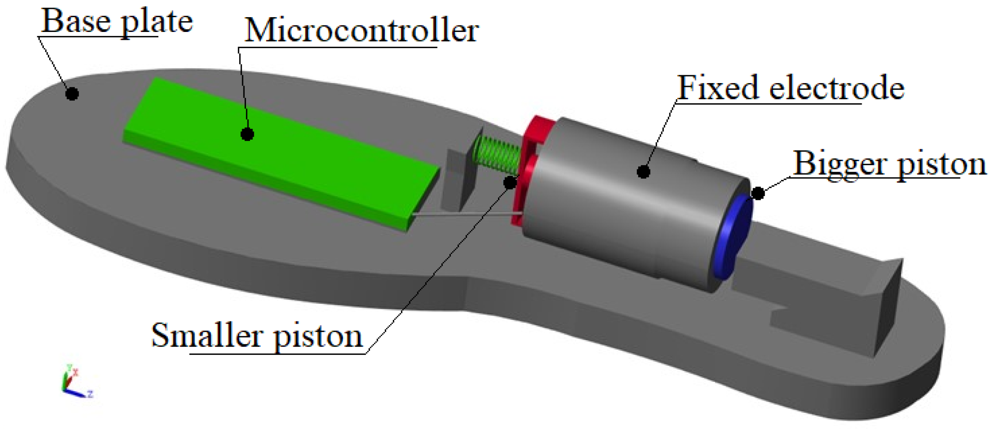
- Demonstration of application of the energy harvester for an in-shoe sensor to deliver peak power density of 0.747 mW/m2 and ability to detect walking anomaly and perform step counting.
2. Materials and Methods
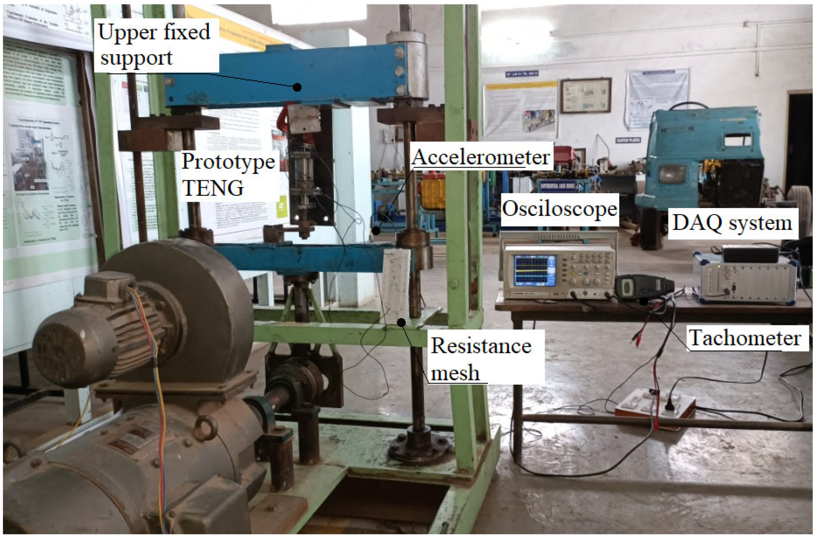
2.1. Prototype and Experimentation Details
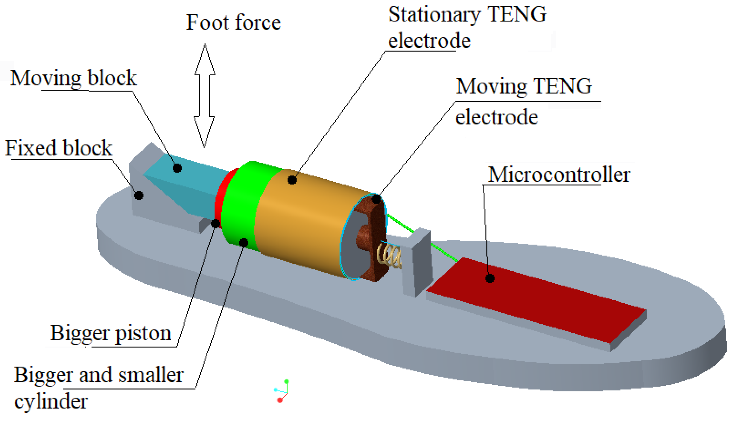
2.1.1. Prototype Details
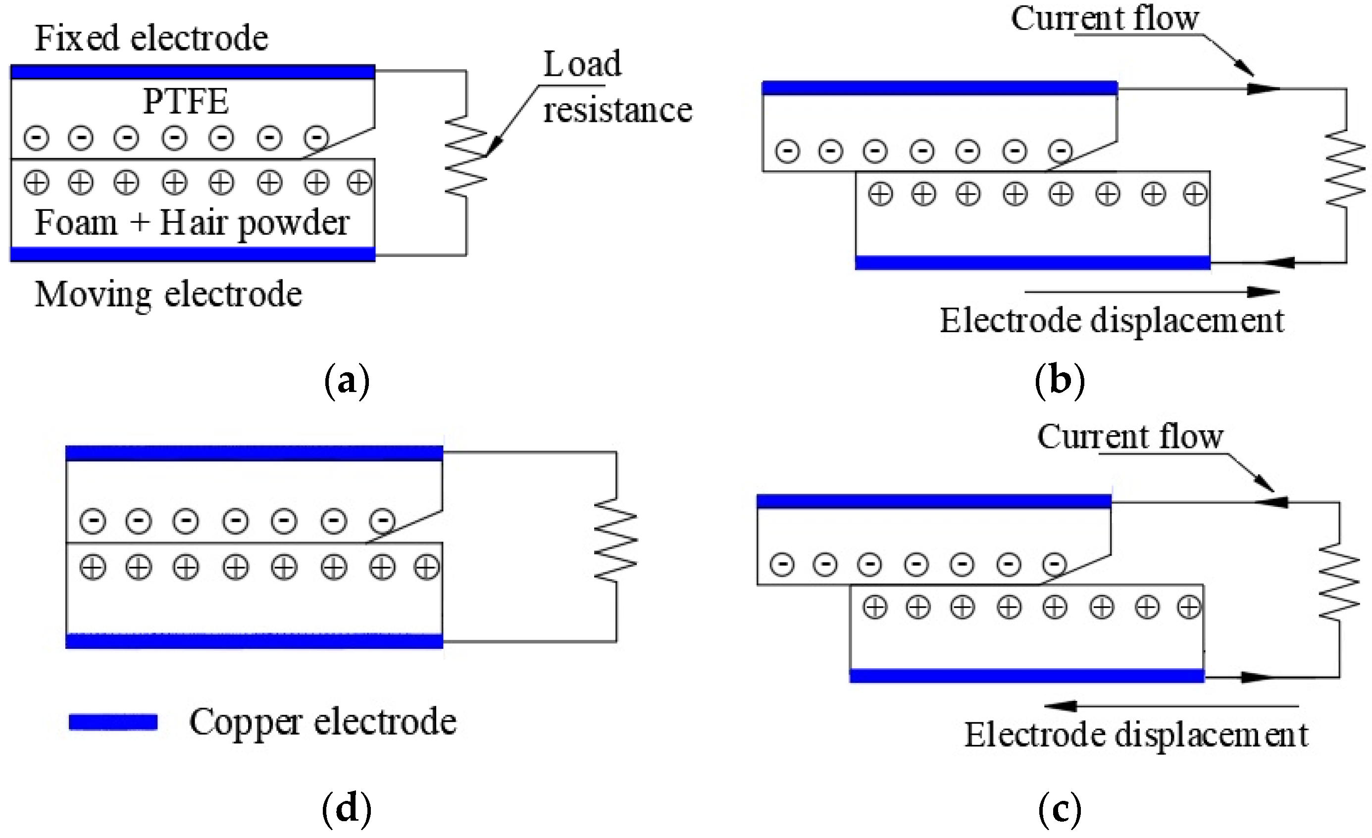
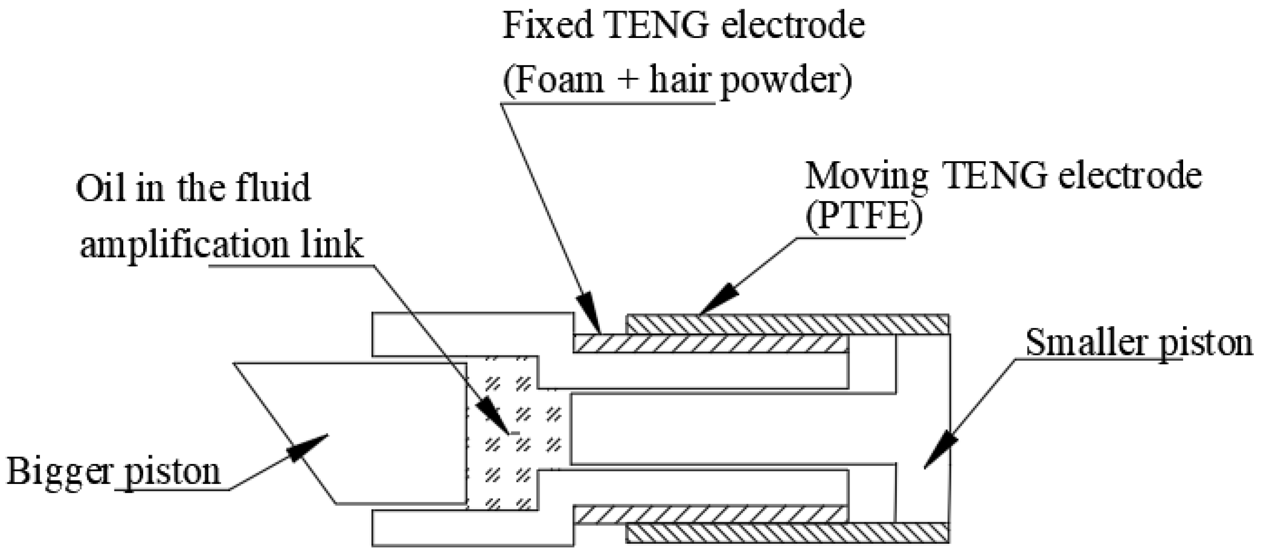
- PTFE and foam thickness: 0.5 mm
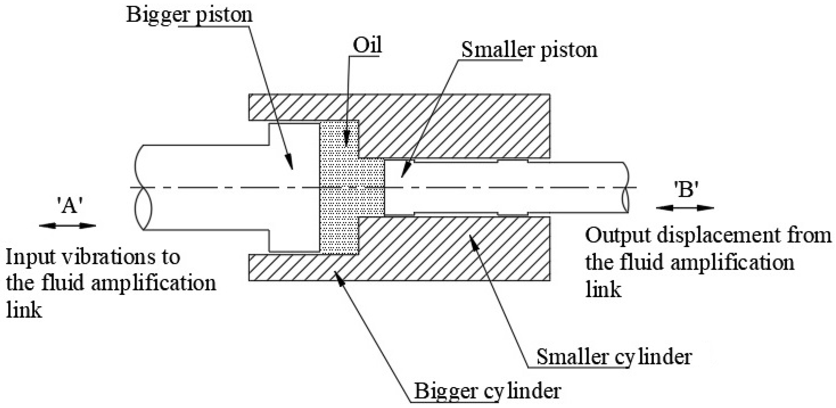
- Diameter of bigger piston in the fluid amplification link: 32 mm
- Diameter of smaller piston in the fluid amplification link: 4 mm
- Dimensions of the foam and PTFE electrode:40 mm in Width and 30 mm in Length
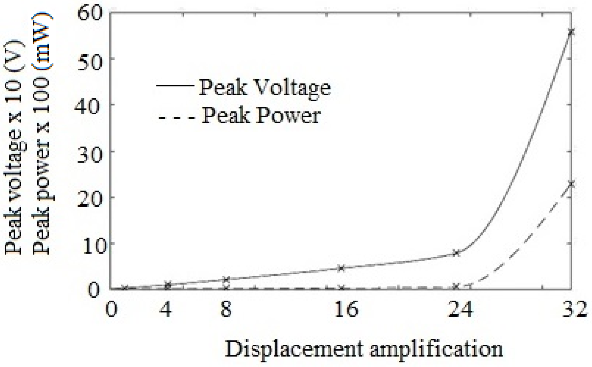
- TENG electrode relative displacement: 32 mm (Displacement amplification of 64.0)
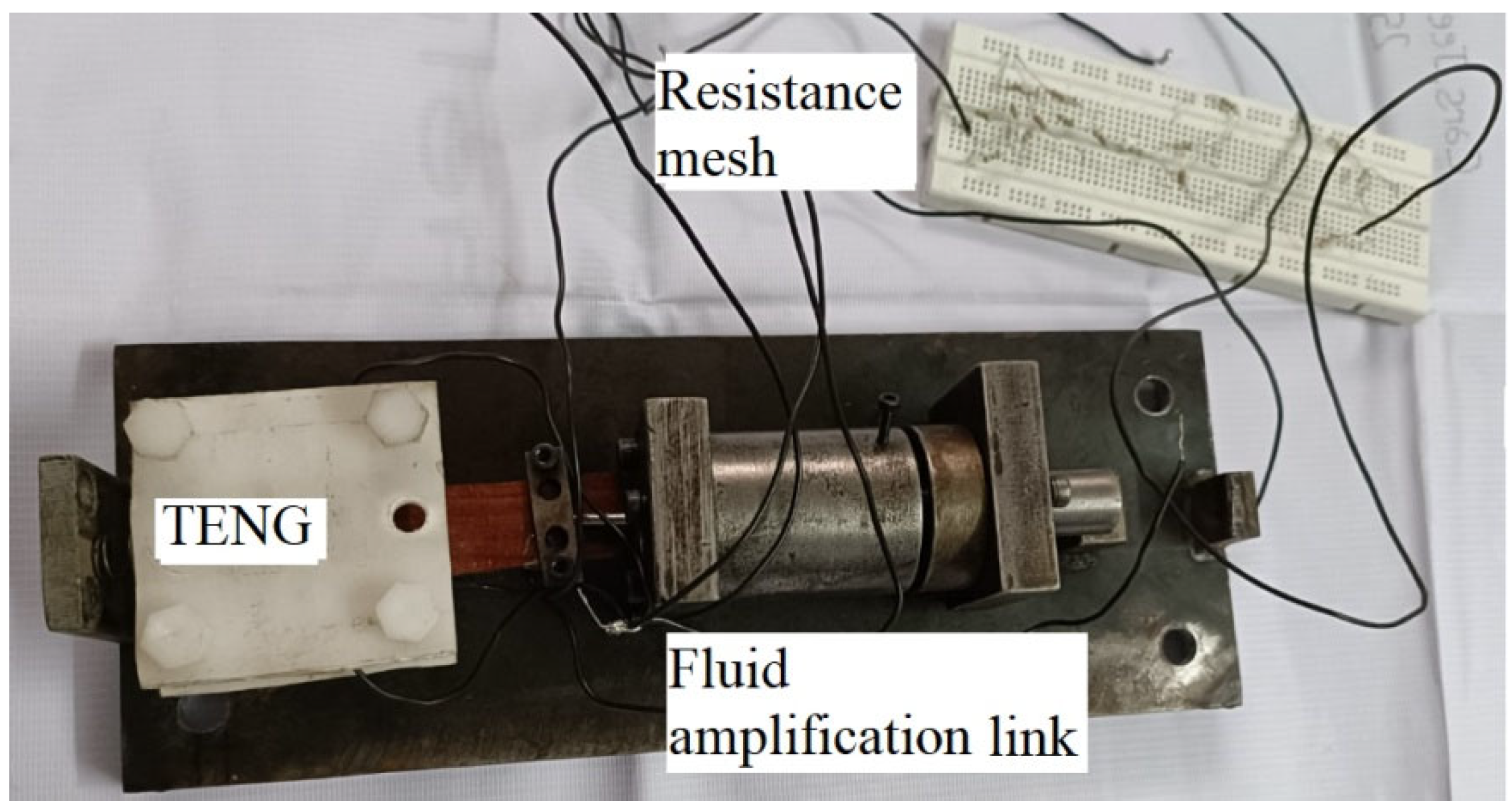
2.1.2. Experimentation Details
3. Mathematical Modeling
- F: force at the input of fluid amplification link;
- d: diameter of the smaller piston in the fluid amplification link;
- D: diameter of the bigger piston in the fluid amplification link;
- Fpf: Piston friction at the fluid amplification link;
- Fdf: Friction force between the sliding dielectric materials of TENG;
- Fff: Force due to fluid friction inside the cylinders of fluid amplification link;
- k: Restoring spring stiffness; and
- x: Displacement of the TENG moving electrode.
- ρ: oil density;
- ʋ: oil kinematic viscosity;
- Leq: equivalent length of pipe;
- dh: hydraulic diameter of the smaller cylinder; and
- d: diameter of the smaller cylinder.
- R: external load resistance;
- Q: charge induced at the electrodes;
- W: width of the electrode;
- z: separation distance;
- d1: thickness of PTFE electrode;
- d2: thickness of foam electrode;
- ε0: free space permittivity;
- l: electrode length;
- εr1: relative permittivity of PTFE;
- εr2: relative permittivity of foam and hair powder; and
- σ: surface charge density.
4. Results and Discussion
- Thickness of PTFE and foam electrodes: 0.5 mm;
- Smaller and bigger piston diameter in the fluid amplification link: 16 mm and 4 mm;
- Surface area of TENG electrode: 640.56 mm2;
- Optimized load resistance for maximum power of 0.3550 mW: 140 MΩ;
- Recommended load resistance: 400 MΩ; and
- Restoring spring stiffness: 500 N/m.
5. Conclusions
Author Contributions
Funding
Informed Consent Statement
Data Availability Statement
Acknowledgments
Conflicts of Interest
References
- Lin, Z.; Chen, J.; Yang, J. Recent progress in triboelectric nanogenerators as a renewable and sustainable power source. J. Nanomater. 2016, 2016, 5651613. [Google Scholar] [CrossRef]
- Hou, C.; Chen, T.; Li, Y.; Huang, M.; Shi, Q.; Liu, H.; Lee, C. A rotational pendulum based electromagnetic/triboelectric hybrid-generator for ultra-low-frequency vibrations aiming at human motion and blue energy applications. Nano Energy 2019, 63, 103871. [Google Scholar] [CrossRef]
- Sukumaran, C.; Vivekananthan, V.; Mohan, V.; Alex, Z.C.; Chandrasekhar, A.; Kim, S.J. Triboelectric nanogenerators from reused plastic: An approach for vehicle security alarming and tire motion monitoring in rover. Appl. Mater. Today 2020, 19, 100625. [Google Scholar] [CrossRef]
- Zou, H.; Guo, L.; Xue, H.; Zhang, Y.; Shen, X.; Liu, X.; Wang, Z.L. Quantifying and understanding the triboelectric series of inorganic non-metallic materials. Nat. Commun. 2020, 11, 1–7. [Google Scholar] [CrossRef]
- Wang, Y.; Yang, Y.; Wang, Z.L. Triboelectric nanogenerators as flexible power sources. npj Flex. Electron. 2017, 1, 10. [Google Scholar] [CrossRef]
- Pan, S.; Zhang, Z. Fundamental theories and basic principles of triboelectric effect: A review. Friction 2019, 7, 2–17. [Google Scholar] [CrossRef]
- Bai, P.; Zhu, G.; Liu, Y.; Chen, J.; Jing, Q.; Yang, W.; Wang, Z.L. Cylindrical rotating triboelectric nanogenerator. ACS Nano 2013, 7, 6361–6366. [Google Scholar] [CrossRef]
- Nguyen, V.; Yang, R. Effect of humidity and pressure on the triboelectric nanogenerator. Nano Energy 2013, 2, 604–608. [Google Scholar] [CrossRef]
- Wang, K.; Qiu, Z.; Wang, J.; Liu, Y.; Chen, R.; An, H.; Kim, T.W. Effect of relative humidity on the enhancement of the triboelectrification efficiency utilizing water bridges between triboelectric materials. Nano Energy 2022, 93, 106880. [Google Scholar] [CrossRef]
- Han, S.A.; Seung, W.; Kim, J.H.; Kim, S.W. Ultrathin noncontact-mode turboelectric nanogenerator triggered by giant dielectric material adaption. ACS Energy Lett. 2021, 6, 1189–1197. [Google Scholar] [CrossRef]
- Dewi, A.S.P.; Mufti, N.; Fibriyanti, A.A.; Diantoro, M.; Taufiq, A.; Hidayat, A.; Nur, H. The improvement of Triboelectric effect of ZnO Nanorods/PAN in flexible Nanogenerator by adding TiO2 nanoparticle. J. Polym. Res. 2020, 27, 139. [Google Scholar] [CrossRef]
- Zou, Y.; Xu, J.; Chen, K.; Chen, J. Advances in Nanostructures for High-Performance Triboelectric Nanogenerators. Adv. Mater. Technol. 2021, 6, 2000916. [Google Scholar] [CrossRef]
- Xie, Z.; Zeng, Z.; Wang, Y.; Yang, W.; Xu, Y.; Lu, X.; Wang, Z.L. Novel sweep-type triboelectric nanogenerator utilizing single freewheel for random triggering motion energy harvesting and driver habits monitoring. Nano Energy 2020, 68, 104360. [Google Scholar] [CrossRef]
- Yao, X. A flexible triboelectric nanogenerator based on soft foam for rehabilitation monitor after foot surgery. Mater. Technol. 2022, 37, 1516–1522. [Google Scholar] [CrossRef]
- Su, Y.; Chen, G.; Chen, C.; Gong, Q.; Xie, G.; Yao, M.; Chen, J. Self-powered respiration monitoring enabled by a triboelectric nanogenerator. Adv. Mater. 2021, 33, 2101262. [Google Scholar] [CrossRef] [PubMed]
- Hu, S.; Weber, J.; Chang, S.; Xiao, G.; Lu, J.; Gao, J.; Tao, Y. A Low-Cost Simple Sliding Triboelectric Nanogenerator for Harvesting Energy from Human Activities. Adv. Mater. Technol. 2022, 7, 2200186. [Google Scholar] [CrossRef]
- Xu, G.; Zheng, Y.; Feng, Y.; Ma, S.; Luo, N.; Feng, M.; Wang, D. A triboelectric/electromagnetic hybrid generator for efficient wind energy collection and power supply for electronic devices. Science. Sci. China Technol. 2021, 64, 2003–2011. [Google Scholar] [CrossRef]
- Lu, X.; Zheng, L.; Zhang, H.; Wang, W.; Wang, Z.L.; Sun, C. Stretchable, transparent triboelectric nanogenerator as a highly sensitive self-powered sensor for driver fatigue and distraction monitoring. Nano Energy 2020, 78, 105359. [Google Scholar] [CrossRef]
- Wu, Y.; Li, Y.; Zou, Y.; Rao, W.; Gai, Y.; Xue, J.; Li, Z. A multi-mode triboelectric nanogenerator for energy harvesting and biomedical monitoring. Nano Energy 2022, 92, 106715. [Google Scholar] [CrossRef]
- Choi, A.Y.; Lee, C.J.; Park, J.; Kim, D.; Kim, Y.T. Corrugated textile based triboelectric generator for wearable energy harvesting. Sci. Rep. 2017, 7, 45583. [Google Scholar] [CrossRef]
- Tian, Z.; Shao, G.; Zhang, Q.; Geng, Y.; Chen, X. A shared-electrode and nested-tube structure triboelectric nanogenerator for motion energy harvesting. Micromachines 2019, 10, 656. [Google Scholar] [CrossRef] [PubMed]
- Kim, D.; Park, J.; Kim, Y.T. Core-shell and helical-structured cylindrical triboelectric nanogenerator for wearable energy harvesting. ACS Appl. Energy Mater. 2019, 2, 1357–1362. [Google Scholar] [CrossRef]
- He, W.; Liu, W.; Chen, J.; Wang, Z.; Liu, Y.; Pu, X.; Hu, C. Boosting output performance of sliding mode triboelectric nanogenerator by charge space-accumulation effect. Nat. Commun. 2020, 11, 4277. [Google Scholar] [CrossRef]
- Ryu, H.; Lee, J.H.; Khan, U.; Kwak, S.S.; Hinchet, R.; Kim, S.W. Sustainable direct current powering a triboelectric nanogenerator via a novel asymmetrical design. Energy Environ. Sci. 2018, 11, 2057–2063. [Google Scholar] [CrossRef]
- Zhang, J.H.; Li, Y.; Hao, X. A high-performance triboelectric nanogenerator with improved output stability by construction of biomimetic superhydrophobic nanoporous fibers. Nanotechnology 2020, 31, 215401. [Google Scholar] [CrossRef]
- Wang, Y.; Pham, A.T.T.; Tohl, D.; Tang, Y. Simulation Guided Hand-Driven Portable Triboelectric Nanogenerator: Design, Optimisation, and Evaluation. Micromachines 2021, 12, 955. [Google Scholar] [CrossRef]
- Zhang, B.; Tian, G.; Xiong, D.; Yang, T.; Chun, F.; Zhong, S.; Yang, W. Understanding the percolation effect in triboelectric nanogenerator with conductive intermediate layer. Research 2021, 2021, 7189376. [Google Scholar] [CrossRef]
- Sun, Q.; Wang, L.; Yue, X.; Zhang, L.; Ren, G.; Li, D.; Huang, W. Fully sustainable and high-performance fish gelatin-based triboelectric nanogenerator for wearable movement sensing and human-machine interaction. Nano Energy 2021, 89, 106329. [Google Scholar] [CrossRef]
- Singh, M.; Sheetal, A.; Singh, H.; Sawhney, R.S.; Kaur, J. Animal hair-based triboelectric nanogenerator (TENG): A substitute for the positive polymer layer in TENG. J. Electron. Mater. 2020, 49, 3409–3416. [Google Scholar] [CrossRef]
- Zhang, H.; Zhang, P.; Li, P.; Deng, L.; Zhang, W.; Liu, B.; Yang, Z. Enhanced performance triboelectric nanogenerator based on porous structure C/MnO2 nanocomposite for energy harvesting. Nano Res. 2022, 15, 7163–7171. [Google Scholar] [CrossRef]
- Wu, C.; Wang, A.C.; Ding, W.; Guo, H.; Wang, Z.L. Triboelectric nanogenerator: A foundation of the energy for the new era. Adv. Energy Mater. 2019, 9, 1802906. [Google Scholar] [CrossRef]
- Qian, J.; Kim, D.S.; Lee, D.W. On-vehicle triboelectric nanogenerator enabled self-powered sensor for tire pressure monitoring. Nano Energy 2018, 49, 126–136. [Google Scholar] [CrossRef]
- Heo, D.; Chung, J.; Kim, B.; Yong, H.; Shin, G.; Cho, J.W.; Lee, S. Triboelectric speed bump as a self-powered automobile warning and velocity sensor. Nano Energy 2020, 72, 104719. [Google Scholar] [CrossRef]
- Luo, J.; Gao, W.; Wang, Z.L. The triboelectric nanogenerator as an innovative technology toward intelligent sports. Adv. Mater. 2021, 33, 2004178. [Google Scholar] [CrossRef] [PubMed]
- Feng, H.; Zhao, C.; Tan, P.; Liu, R.; Chen, X.; Li, Z. Nanogenerator for biomedical applications. Adv. Healthcare Mater. 2018, 7, 1701298. [Google Scholar] [CrossRef]
- Wang, M.; Li, W.; You, C.; Wang, Q.; Zeng, X.; Chen, M. Triboelectric nanogenerator based on 317L stainless steel and ethyl cellulose for biomedical applications. RSC Adv. 2017, 7, 6772–6779. [Google Scholar] [CrossRef]
- Li, J.; Long, Y.; Yang, F.; Wang, X. Respiration-driven triboelectric nanogenerators for biomedical applications. EcoMat 2020, 2, e12045. [Google Scholar] [CrossRef]
- Parandeh, S.; Kharaziha, M.; Karimzadeh, F.; Hosseinabadi, F. Triboelectric nanogenerators based on graphene oxide coated nanocomposite fibers for biomedical applications. Nanotechnology 2020, 31, 385402. [Google Scholar] [CrossRef]
- Sun, J.; Li, W.; Liu, G.; Li, W.; Chen, M. Triboelectric nanogenerator based on biocompatible polymer materials. J. Phys. Chem. C 2015, 119, 9061–9068. [Google Scholar] [CrossRef]
- Liu, Y.; Zhao, W.; Liu, G.; Bu, T.; Xia, Y.; Xu, S.; Zhang, H. Self-powered artificial joint wear debris sensor based on triboelectric nanogenerator. Nano Energy 2021, 85, 105967. [Google Scholar] [CrossRef]
- Liao, J.; Zou, Y.; Jiang, D.; Liu, Z.; Qu, X.; Li, Z.; Zheng, L. Nestable arched triboelectric nanogenerator for large deflection biomechanical sensing and energy harvesting. Nano Energy 2020, 69, 104417. [Google Scholar] [CrossRef]
- Zhang, B.; Wu, Z.; Lin, Z.; Guo, H.; Chun, F.; Yang, W.; Wang, Z.L. All-in-one 3D acceleration sensor based on coded liquid–metal triboelectric nanogenerator for vehicle restraint system. Mater. Today 2021, 43, 37–44. [Google Scholar] [CrossRef]
- Zhang, B.; Gu, Y.; Guo, H.; Gao, Y.; Zou, Y.; Zhang, R.; Yang, W. Sustainable tunnel lighting system based on mechanical-regulated and soft-contact hybridized nanogenerator. Nano Energy 2022, 104, 107868. [Google Scholar] [CrossRef]
- Liu, H.; Wang, H.; Lyu, Y.; He, C.; Liu, Z. A novel triboelectric nanogenerator based on carbon fiber reinforced composite lamina and as a self-powered displacement sensor. Microelectron. Eng. 2020, 224, 111231. [Google Scholar] [CrossRef]
- Li, X.; Cao, Y.; Yu, X.; Xu, Y.; Yang, Y.; Liu, S.; Wang, Z.L. Breeze-driven triboelectric nanogenerator for wind energy harvesting and application in smart agriculture. Appl. Energy 2022, 306, 117977. [Google Scholar] [CrossRef]
- Xia, K.; Du, C.; Zhu, Z.; Wang, R.; Zhang, H.; Xu, Z. Sliding-mode triboelectric nanogenerator based on paper and as a self-powered velocity and force sensor. Appl. Mater. Today 2018, 13, 190–197. [Google Scholar] [CrossRef]
- Candido, I.C.M.; da S. Oliveira, G.; Viana, G.G.; da Silva, F.A.G., Jr.; da Costa, M.M.; de Oliveira, H.P. Wearable Triboelectric Nanogenerators Based on Chemical Modification of Conventional Textiles for Application in Electrically Driven Antibacterial Devices. ACS Appl. Electron. Mater. 2021, 4, 334–344. [Google Scholar]
- Chen, C.; Guo, H.; Chen, L.; Wang, Y.C.; Pu, X.; Yu, W.; Wang, Z.L. Direct current fabric triboelectric nanogenerator for biomotion energy harvesting. ACS Nano. 2020, 14, 4585–4594. [Google Scholar] [CrossRef]
- Zi, Y.; Wang, J.; Wang, S.; Li, S.; Wen, Z.; Guo, H.; Wang, Z.L. Effective energy storage from a triboelectric nanogenerator. Nat. Commun. 2016, 7, 10987. [Google Scholar] [CrossRef]
- Pu, X.; Liu, M.; Li, L.; Zhang, C.; Pang, Y.; Jiang, C.; Wang, Z.L. Efficient charging of Li-ion batteries with pulsed output current of triboelectric nanogenerators. Adv. Sci. 2016, 3, 1500255. [Google Scholar] [CrossRef]
- Kouritem, S.A.; Altabey, W.A. Ultra-broadband natural frequency using automatic resonance tuning of energy harvester and deep learning algorithms. Energy Convers. Manag. 2022, 272, 116332. [Google Scholar] [CrossRef]
- Kouritem, S.A.; Bani-Hani, M.A.; Beshir, M.; Elshabasy, M.M.; Altabey, W.A. Automatic Resonance Tuning Technique for an Ultra-Broadband Piezoelectric Energy Harvester. Energies 2022, 15, 7271. [Google Scholar] [CrossRef]
- Bani-Hani, M.A.; Almomani, A.M.; Aljanaideh, K.F.; Kouritem, S.A. Mechanical Modeling and Numerical Investigation of Earthquake-Induced Structural Vibration Self-Powered Sensing Device. IEEE Sens. J. 2022, 22, 19237–19248. [Google Scholar] [CrossRef]
- Aabid, A.; Raheman, M.A.; Ibrahim, Y.E.; Anjum, A.; Hrairi, M.; Parveez, B.; Mohammed, Z.J. A systematic review of piezoelectric materials and energy harvesters for industrial applications. Sensors 2021, 21, 4145. [Google Scholar] [CrossRef] [PubMed]
- An, X.; Wang, C.; Shao, R.; Sun, S. Advances and prospects of triboelectric nanogenerator for self-powered system. Int. J. Smart Nano Mater. 2021, 12, 233–255. [Google Scholar] [CrossRef]
- Zhao, J.; Zhen, G.; Liu, G.; Bu, T.; Liu, W.; Fu, X.; Wang, Z.L. Remarkable merits of triboelectric nanogenerator than electromagnetic generator for harvesting small-amplitude mechanical energy. Nano Energy 2019, 61, 111–118. [Google Scholar] [CrossRef]
- Mao, Y.; Zhu, Y.; Zhao, T.; Jia, C.; Wang, X.; Wang, Q. Portable Mobile Gait Monitor System Based on Triboelectric Nanogenerator for Monitoring Gait and Powering Electronics. Energies 2021, 14, 4996. [Google Scholar] [CrossRef]
- Cui, X.; Zhao, T.; Yang, S.; Xie, G.; Zhang, Z.; Zhang, Y.; Zhang, H. A spongy electrode-brush-structured dual-mode triboelectric nanogenerator for harvesting mechanical energy and self-powered trajectory tracking. Nano Energy 2020, 78, 105381. [Google Scholar] [CrossRef]
- Zhang, H.; Quan, L.W. Theoretical prediction and optimization approach to triboelectric nanogenerator. In Electrostatic Discharge from Electrical Breakdown in Micro-Gaps to Nano-Generators; IntechOpen: London, UK, 2019; pp. 69–89. [Google Scholar]
- Liu, T.; Inoue, Y.; Shibata, K. Development of a wearable sensor system for quantitative gait analysis. Measurement 2009, 42, 978–988. [Google Scholar] [CrossRef]
- Więckowski, J.S.; Pietrusiak, D.; Rafajłowicz, W. Low frequency vibration in Heavy Machinery-preliminary identification and control. In Proceedings of the ISMA2020-International Conference on Noise and Vibration Engineering, Banagalore, India, 27–28 February 2020; pp. 3261–3270. [Google Scholar]
- Lahdelma, S.; Juuso, E. Generalised lp norms in vibration analysis of process equipments. In Proceedings of the 7th International Conference on Condition Monitoring and Machinery Failure Prevention Technologies, CM 2010/MFPT. Nottingham, UK, 22–24 June 2010. [Google Scholar]
- Cengel, Y.A.; Cimbala, J. Fluid Mechanics-Fundamentals and Applications; McGraw-Hill: New York, NY, USA, 2006. [Google Scholar]
- Kumar, S.; Singh, T.P.; Kumar, R.; Jain, S.C. Experiment and parametric analysis of sliding mode triboelectric energy harvester. Mech. Based Des. Struct. Mach. 2022, 50, 1–15. [Google Scholar] [CrossRef]
- Niu, S.; Liu, Y.; Wang, S.; Lin, L.; Zhou, Y.S.; Hu, Y.; Wang, Z.L. Theory of sliding-mode triboelectric nanogenerators. Adv. Mater. 2013, 25, 6184–6193. [Google Scholar] [CrossRef] [PubMed]
- Jayaweera, E.N.; Wijewardhana, K.R.; Ekanayaka, T.K.; Shahzad, A.; Song, J.K. Triboelectric nanogenerator based on human hair. ACS Sustain. Chem. Eng. 2018, 6, 6321–6327. [Google Scholar] [CrossRef]
- Zhang, R.; Hummelgård, M.; Örtegren, J.; Olsen, M.; Andersson, H.; Yang, Y.; Olin, H. The triboelectricity of the human body. Nano Energy 2021, 86, 106041. [Google Scholar] [CrossRef]
- Chun, J.; Ye, B.U.; Lee, J.W.; Choi, D.; Kang, C.Y.; Kim, S.W.; Wang, L.Z.; Baik, J.M. Boosted output performance of triboelectric nanogenerator via electric double layer effect. Nat. Commun. 2016, 7, 12985. [Google Scholar] [CrossRef]
- Lee, Y.; Kang, S.G.; Jeong, J. Sliding triboelectric nanogenerator with staggered electrodes. Nano Energy 2021, 86, 106062. [Google Scholar] [CrossRef]
- Ding, Y.; Khazoom, C.; Chignoli, M.; Kim, S. Dynamic Walking with Footstep Adaptation on the MIT Humanoid via Linear Model Predictive Control. arXiv 2022, arXiv:2205.15443. [Google Scholar]
- Yu, T.; Jin, H.; Nahrstedt, K. Shoesloc: In-shoe force sensor-based indoor walking path tracking. Proc. ACM Interact. Mob. Wearable Ubiquitous Technol. 2019, 3, 1–23. [Google Scholar]
- Yang, W.; Chen, J.; Zhu, G.; Yang, J.; Bai, P.; Su, Y.; Wang, Z.L. Harvesting energy from the natural vibration of human walking. ACS Nano. 2013, 7, 11317–11324. [Google Scholar] [CrossRef]
- Vivekananthan, V.; Kim, W.J.; Alluri, N.R.; Purusothaman, Y.; Abisegapriyan, K.S.; Kim, S.J. Asliding mode contact electrification based triboelectric-electromagnetic hybrid generator for small-scale biomechanical energy harvesting. Micro Nano Syst. Lett. 2019, 7, 14. [Google Scholar] [CrossRef]
- Pang, Y.; Chen, S.; Chu, Y.; Wang, Z.L.; Cao, C. Matryoshka-inspired hierarchically structured triboelectric nanogenerators for wave energy harvesting. Nano Energy 2019, 66, 104131. [Google Scholar] [CrossRef]
- Jiao, J.; Lu, Q.; Wang, Z.; Qin, Y.; Cao, X. Sandwich as a triboelectric nanogenerator. Nano Energy 2021, 79, 105411. [Google Scholar] [CrossRef]
- Long, L.; Liu, W.; Wang, Z.; He, W.; Li, G.; Tang, Q.; Hu, C. High performance floating self-excited sliding triboelectric nanogenerator for micro mechanical energy harvesting. Nat. Commun. 2021, 12, 4689. [Google Scholar] [CrossRef] [PubMed]
- Li, Y.; Zhao, Z.; Gao, Y.; Li, S.; Zhou, L.; Wang, J.; Wang, Z.L. Low-cost, environmentally friendly, and high-performance triboelectric nanogenerator based on a common waste material. ACS Appl. Mater. Interfaces 2021, 13, 30776–30784. [Google Scholar] [CrossRef] [PubMed]
- Nie, S.; Fu, Q.; Lin, X.; Zhang, C.; Lu, Y.; Wang, S. Enhanced performance of a cellulose nanofibrils-based triboelectric nanogenerator by tuning the surface polarizability and hydrophobicity. Chem. Eng. J. 2021, 404, 126512. [Google Scholar] [CrossRef]
- Guo, T.; Liu, G.; Pang, Y.; Wu, B.; Xi, F.; Zhao, J.; Wang, Z.L. Compressible hexagonal-structured triboelectric nanogenerators for harvesting tire rotation energy. Extreme Mech. Lett. 2018, 18, 1–8. [Google Scholar] [CrossRef]
- Askari, H.; Saadatnia, Z.; Khajepour, A.; Khamesee, M.B.; Zu, J. A triboelectric self-powered sensor for tire condition monitoring: Concept, design, fabrication, and experiments. Adv. Eng. Mater. 2017, 19, 1700318. [Google Scholar] [CrossRef]
- Xu, X.; Wu, Q.; Pang, Y.; Cao, Y.; Fang, Y.; Huang, G.; Cao, C. Multifunctional Metamaterials for Energy Harvesting and Vibration Control. Adv. Funct. Mater. 2022, 32, 2107896. [Google Scholar] [CrossRef]


| Element | Mass Percentage (%) |
|---|---|
| Carbon | 59.37 |
| Oxygen | 34.19 |
| Sulphur | 2.04 |
| Calcium | 1.55 |
| Iron | 1.47 |
| Silicon | 1.39 |
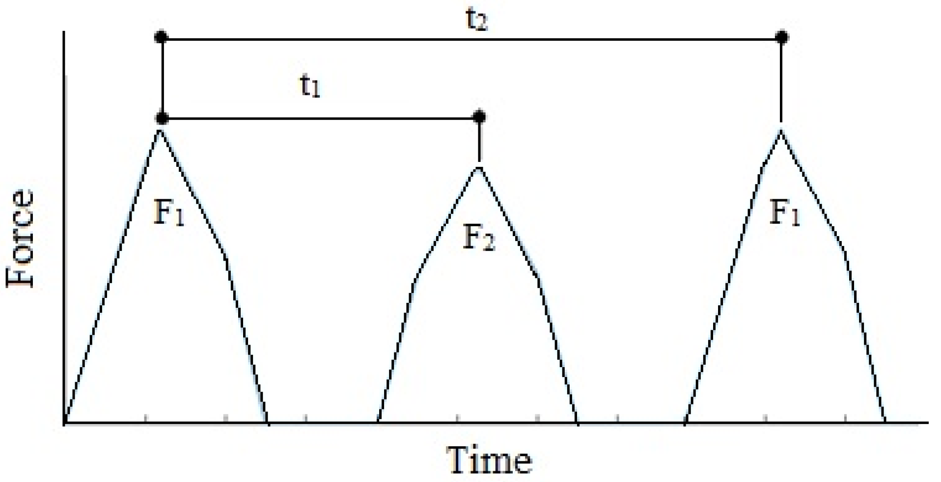
| F1 | F2 | t1 (s) | t2 (s) | |
|---|---|---|---|---|
| Pattern 1 | 100 N | 80 N | 0.5 | 1.7 |
| Pattern 2 | 80 N | 64 N | 2.1 | 5.7 |
| Pattern 3 | 70 N | 60 N | 8.2 | 15.1 |
| Sr. No. | Reference | Materials Used | Power Density | Total Displacement of Electrodes |
|---|---|---|---|---|
| 1 | Zhao et al., 2019 [59] | Acrylic sheet and FEP | 0.25 mW/m2 | 1 mm |
| 2 | Yang et al., 2013 [72] | PTFE and Aluminium operating in sliding mode | 350 mW/m2 for 100 MΩ electric load | 16 mm |
| 3 | Liu et al., 2020 [45] | Carbon fiber reinforced composite lamina and papers operating in sliding mode | 4.2 mW/m2 for 100 MΩ electric load | 4 mm at 5 Hz |
| 4 | Vivekananthan et al., 2019 [73] | Paper and Kapton films in sliding mode | 1.07 mW/m2 for 16,110 Ω electric load | 10 mm |
| 5 | Pang et al., 2019 [74] | PTFE balls and Acrylic shell | 544 mW/m2 | 60 mm at 2 Hz |
| 6 | Zou et al., 2021 [12] | FEP film and Aluminium in sliding mode | 190 mW/m2 | 50 mm by hand motion |
| 7 | Jiao et al., 2020 [75] | Bread and natural vegetable | 45 µW open circuit power | 20 mm |
| 8 | Long et al., 2021 [76] | PTFE and Nylon film in rotary mode | 13 nm/m2 | 360° rotations of the electrode |
| 9 | Li et al., 2021 [77] | Katpon and Silicone in contact separation mode | 5 nm/m2 | Not reported |
| 10 | Nie et al., 2021 [78] | Cellulode nanofibrils and Trirthoxy-tridecafluore-octylsilane in contact separation mode | 13 mW/m2 for 55 MΩ electric load for 50 N force | Not reported |
| 11 | Guo et al., 2017 [79] | Polymide and Fluorinated ethylene propylene in contact separation mode | 17.29 mW/m2 for 65 MΩ electric load for 10 N force | Not reported |
| 12 | Askari et al., 2017 [80] | Polyurethane and Kapton layers in hybrid mode | 63 mW/m3 for 100 MΩ electric load | 35 mm |
| 13 | Xu et al., 2022 [81] | Metamaterial structure with PTFE and nylon | Open circuit voltage up to 12 V | 2.2–15 mm |
| 14 | This work | PTFE and Memory foam with human hair micropowder | Prototype: 0.262 mW/m2 for 130 MΩ of electric load Real size design in-shoe sensor: 0.747 mW/m2 for 140 MΩ of electric load | 1.0 mm |
Disclaimer/Publisher’s Note: The statements, opinions and data contained in all publications are solely those of the individual author(s) and contributor(s) and not of MDPI and/or the editor(s). MDPI and/or the editor(s) disclaim responsibility for any injury to people or property resulting from any ideas, methods, instructions or products referred to in the content. |
© 2023 by the authors. Licensee MDPI, Basel, Switzerland. This article is an open access article distributed under the terms and conditions of the Creative Commons Attribution (CC BY) license (https://creativecommons.org/licenses/by/4.0/).
Share and Cite
Satpute, N.; Iwaniec, M.; Iwaniec, J.; Mhetre, M.; Arawade, S.; Jabade, S.; Banaś, M. Triboelectric Nanogenerator-Based Vibration Energy Harvester Using Bio-Inspired Microparticles and Mechanical Motion Amplification. Energies 2023, 16, 1315. https://doi.org/10.3390/en16031315
Satpute N, Iwaniec M, Iwaniec J, Mhetre M, Arawade S, Jabade S, Banaś M. Triboelectric Nanogenerator-Based Vibration Energy Harvester Using Bio-Inspired Microparticles and Mechanical Motion Amplification. Energies. 2023; 16(3):1315. https://doi.org/10.3390/en16031315
Chicago/Turabian StyleSatpute, Nitin, Marek Iwaniec, Joanna Iwaniec, Manisha Mhetre, Swapnil Arawade, Siddharth Jabade, and Marian Banaś. 2023. "Triboelectric Nanogenerator-Based Vibration Energy Harvester Using Bio-Inspired Microparticles and Mechanical Motion Amplification" Energies 16, no. 3: 1315. https://doi.org/10.3390/en16031315
APA StyleSatpute, N., Iwaniec, M., Iwaniec, J., Mhetre, M., Arawade, S., Jabade, S., & Banaś, M. (2023). Triboelectric Nanogenerator-Based Vibration Energy Harvester Using Bio-Inspired Microparticles and Mechanical Motion Amplification. Energies, 16(3), 1315. https://doi.org/10.3390/en16031315