Review

Active Damping Stabilization Techniques for Cascaded Systems in DC Microgrids: A Comprehensive Review

by
Ranjan Kumar
and
Chandrashekhar N. Bhende
*
School of Electrical Science, Indian Institute of Technology Bhubaneswar, Argul, Khordha 752050, India
*
Author to whom correspondence should be addressed.
Energies 2023, 16(3), 1339; https://doi.org/10.3390/en16031339
Submission received: 21 November 2022 / Revised: 14 January 2023 / Accepted: 21 January 2023 / Published: 27 January 2023
(This article belongs to the Special Issue Trends and Prospects in Photovoltaic Systems)

Abstract

:
Microgrids have arisen as an alternate solution to the problem of power generation in distributed energy. Compared to ac microgrids, dc microgrids (DC MGs) are superior in terms of system efficiency, power quality, affordability, and ease of control. For the integration of renewable energy generation into microgrids, power electronic converters are required. When power electronics converters are tightly regulated, they behave as a constant power load (CPL) which exhibits a negative incremental impedance characteristic. As a result, oscillations occur in voltage response at a DC bus. To suppress the voltage oscillations in DC MGs, various damping stabilization techniques are proposed by researchers. This paper provides a comprehensive review on active damping stabilization techniques. To improve the system’s stability, active damping can be implemented in three distinct zones: source-side, load side or CPL side, and intermediate level. After analyzing each zone, their merits and drawbacks have been presented. Moreover, CPL modelling, performance of cascaded DC-DC systems, the effect of the load on the source subsystem, the effect of the source on the load converter, and stability analysis are discussed. Finally, concluding remarks and future research directions are highlighted.

1. Introduction

Globally: Energy scarcity and related environmental issues are becoming major concerns. On the other hand, the ever-increasing need for electricity is putting a great strain on the present electrical supply system [1,2,3,4]. Renewable and sustainable energy development is a feasible solution to these problems. For the integration of renewable energy generation (REG) into microgrids (MGs), power converters are required [5,6]. The Microgrid Exchange Group (MEG) of the US Department of Energy (DOE) defines the microgrid as follows: “A microgrid is a group of interconnected loads and distributed energy resources within defined electrical borderlines that acts as a single controllable unit with respect to the grid. A microgrid can be connected/disconnected from the grid so that it can operate in grid-connected or island-mode” [7]. Figure 1 shows the typical DC Microgrid (DC MG) architecture, which consists of various micro sources, energy storage systems, energy conversion converters, resistive load and constant power load (CPL). A DC-DC conversion cascaded system is the most popular system in DC MGs and has been extensively employed, such as in more electric aircraft (MEA), satellites, hybrid vehicles, shipboards, electrical vehicles (EV), data centres and renewable applications in the last few decades [8,9,10,11,12]. The DC MG offers several benefits, including simple control, no reactive power and no frequency synchronisation issues. Furthermore, it allows natural connectivity with DC-based renewable energy sources (such as PV), electric loads (such as EVs) and energy storage systems (such as batteries) as compared to the AC Microgrid [13,14].
Therefore, DC MGs have been gaining attention recently. However, voltage stability is one of the issues with DC MGs [15,16].
Stable functioning of the DC MGs should be guaranteed under all situations in addition to voltage and current regulation. Points of load (POL) converters and their associated loads are often considered to be CPL (Figure 2); in particular, the power converter is tightly controlled. However, because of the negative incremental impedance (NII) characteristics of CPL, DC MGs are more prone to be unstable [17,18,19]. As a result, CPL causes limited cycle oscillation, reduced system damping, reduced stability margins, voltage collapse on the DC bus, and in the worst-case scenario, the entire system shutting down [16,20,21,22]. Source-side converters and CPLs are close to each other in some power electronic converter systems, like small power systems in EVs. In these kinds of systems, there is no need for an LC input filter because the output filter of the source-side converter can provide the same function, which reduces the noises caused by switching [18]. Figure 3 shows the typical cascaded DC system that comprises a source converter or input filter in series with a load converter. There is a significant effect on the stability of DC MGs due to the exponential rise in CPLs caused by the growing use of power electronics devices [23]. Electric motors driven by a DC/AC converter (e.g., BLDC motors), DC-DC converters feeding resistive loads and fast DC chargers for EVs that are tightly regulated are examples of CPLs [24,25]. As shown in Figure 3, individually, both the source and load converters can work properly, but the entire system may become unstable due to their impedance interaction reason, as explained in Section 3.3.
To improve the voltage stability of DC MGs, various schemes are proposed in the literature. These schemes are mainly categorized into passive and active damping techniques. Active compensation techniques have numerous advantages over passive damping (discussed in Section 4). Therefore, in this work, an extensive literature review is presented about various active damping methods.
The main contribution of this article can be summarized as follows:
  • This paper reviews the active damping compensation techniques for a cascaded system to stabilize the CPL effects in DC MGs. The merits and drawbacks of each scheme are elaborated.
  • Stability analysis and stability challenges of cascaded system in DC MGs have been presented.
  • The delays in digitally controlled systems and their effect on active damping control have been covered and discussed.
  • This review paves the road for further investigation on active damping control strategies and their application in DC MGs.
The structure of this paper is organized as follows. In Section 2, constant power load (CPL) modelling is presented. In Section 3, performance and stability analysis of cascaded DC-DC systems are discussed. The classification of CPL compensation techniques is reviewed in Section 4. The delays in digitally controlled systems and their effect on active damping control are discussed in Section 5. Finally, the challenges and future research directions of the DC MG, and our conclusions, are presented in Section 6 and Section 7, respectively.

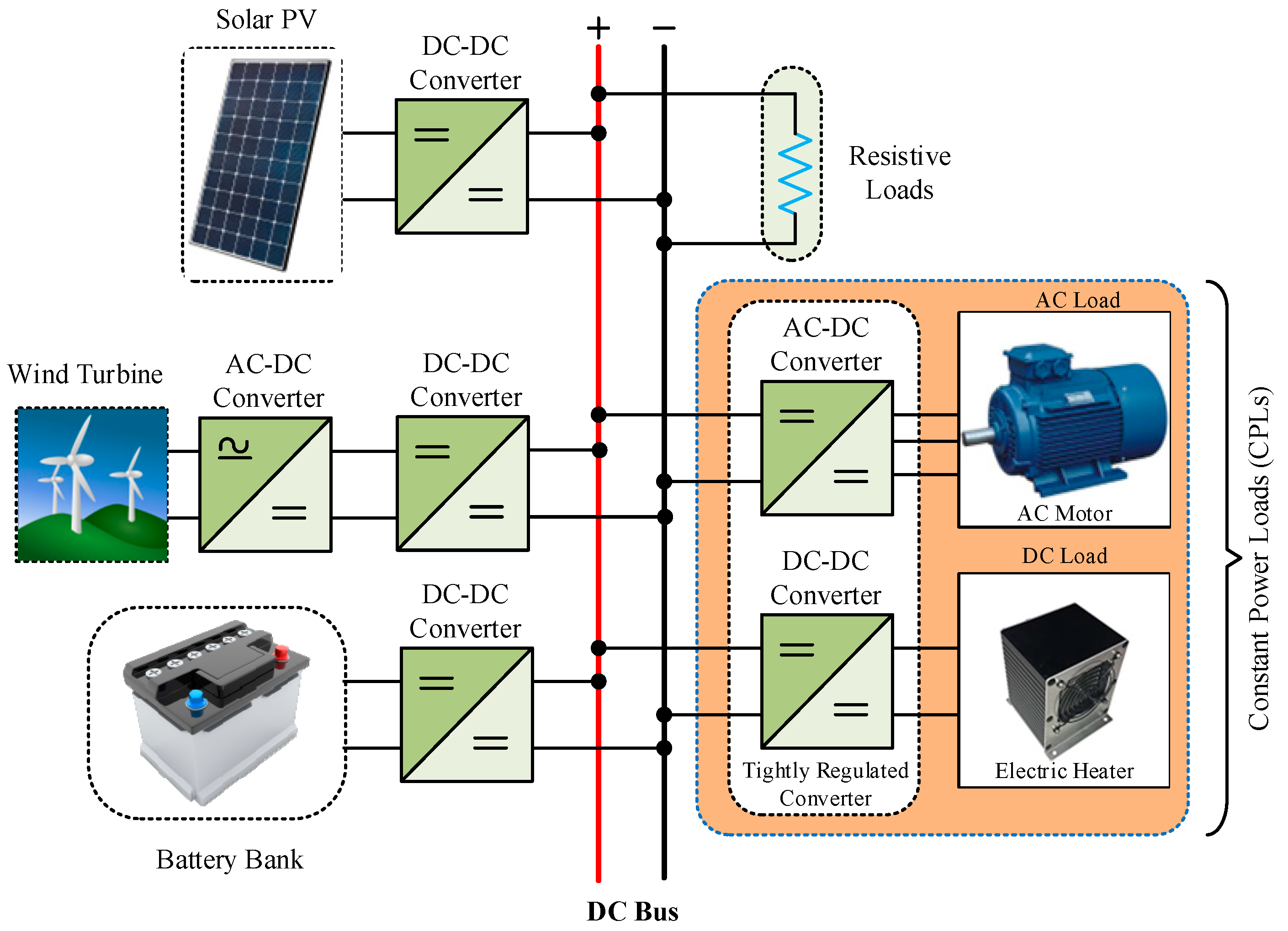
2. Constant Power Load (CPL) Modelling

Tightly regulated POL converters behave as CPLs, exhibiting NII and posing significant instability challenges for DC MGs [26,27,28,29,30,31]. This can be explained as follow: if a disturbance causes the load voltage to fall below the voltage value of the stable point, the load current will be greater than the load current at constant power of the load, resulting in the discharge of the filter capacitor. As a result, the load current will rise to maintain the power constant but the voltage will fall.
In the absence of a proper control mechanism, the voltage will drop to zero and the current will increase to infinity during a transient or any small disturbance [18,32,33,34,35]. Similarly, if the voltage of the source converter varies (i.e., decreases), the duty cycle of the load converter increases to control the voltage, which implies that the current increases to maintain constant power [36,37,38,39,40,41,42]. As a result, in the absence of a properly designed feedback control, the DC bus voltage tends to oscillate, resulting in limit cycle behaviour with an unstable equilibrium point. Limit cycles are undesirable because they create stress on the switches of the source power converters. This stress causes temperature to rise, limiting the lifespan of the switching components, or it may completely damage it [43,44]. Furthermore, the CPL model introduces nonlinearity to the system [45]. Figure 2a depicts the CPL V-I characteristic. As shown in Figure 2b, the current i C P L t through the CPL terminal can be expressed as (1)
i C P L t = P v C P L t
For a given operating point I = P / V , the CPL small signal model can be approximated by a straight line tangent to the curve as seen in Figure 2a, which is computed as (2)
i C P L t = P V 2 v C P L t + 2 P V
Equation (2) can be represented as negative resistance ( R C P L = V 2 / P ) with a parallel constant current source ( I C P L = 2 P / V ) as shown in Figure 2c.

3. Performance and Stability Analysis of Cascaded DC-DC Systems

Several research works have been conducted to solve cascaded system stability issues by establishing the source and the load subsystems at the DC bus interface of the POL converter. Figure 3a depicts the equivalent system divided into two subsystems, the source subsystem and the load subsystem, both of which are considered to be independently stable. G v g , S   and G v g , L are the source and load converter input-to-output voltage stable transfer functions, respectively. Since switched-mode regulators are connected in cascade to form DC-distributed power systems (DPSs), the load converter modifies the dynamics of the source converter and vice versa (explained in Section 3.1 and Section 3.2) [21,46]. As a result, both subsystems suffer from reduced relative stability margins [21]. Therefore, this section explains how cascading two DC-DC converters affect each one’s dynamic performance. A generic cascaded system feeding CPL is depicted in Figure 3a, where, Z i s , Z O s , v i n   v o and v b u s are the input impedance of the load converter, the output impedance of the source converter, the input voltage of the source converter, the output voltage of the load converter and the DC bus voltage, respectively. The conventional model of a single-load-single-source that may be used to study the effect of negative input impedance on cascaded systems is depicted in Figure 3 [21]. The input-to-output voltage relationship for such a system may be defined as
v ^ o v ^ i n = G v g , S   G v g , L 1 + T S 1 + T L 1 + T m
T S and T L are the voltage loop gains of the source and load converters, respectively. T m = Z o / Z i n is called minor loop gain and plays an important role in the stability analysis of the overall system. Connecting the converters adds more poles to the system and affects its dynamic response [47] due to the added component 1 + T m in (3). Each converter in the cascaded system will work individually if T m 1 . T m is critical for guaranteeing both the stability and dynamic performance in order to assure the cascaded system’s stability.

3.1. The Effect of the Load on the Source Subsystem

Because of the loading influence, the loop gain of the source converter is modified when the load converter is involved. This can be seen in [21,48].
T S L = T S 1 + T m 1 + T S
where T S is the control loop gain of the source converter and T S L is the load-affected control loop gain. The source converter’s dynamic performance will be maintained even if Z o 1   ( i . e . ,   T S L T S )

3.2. The Effect of the Source on the Load Converter

According to [47,49], the source converter has an impact on the load converter’s dynamics.
T L S = T L 1 + T m 1 + Z o Z i n _ o l
where Z i n _ o l represents the open-loop input impedance of the load converter, T L represents the control loop gain of the load converter, and T L S represents the source-influenced control loop gain of the load. Similarly, the load dynamic performance will be maintained even if Z o 1   ( i . e . ,   T L S T L ) .

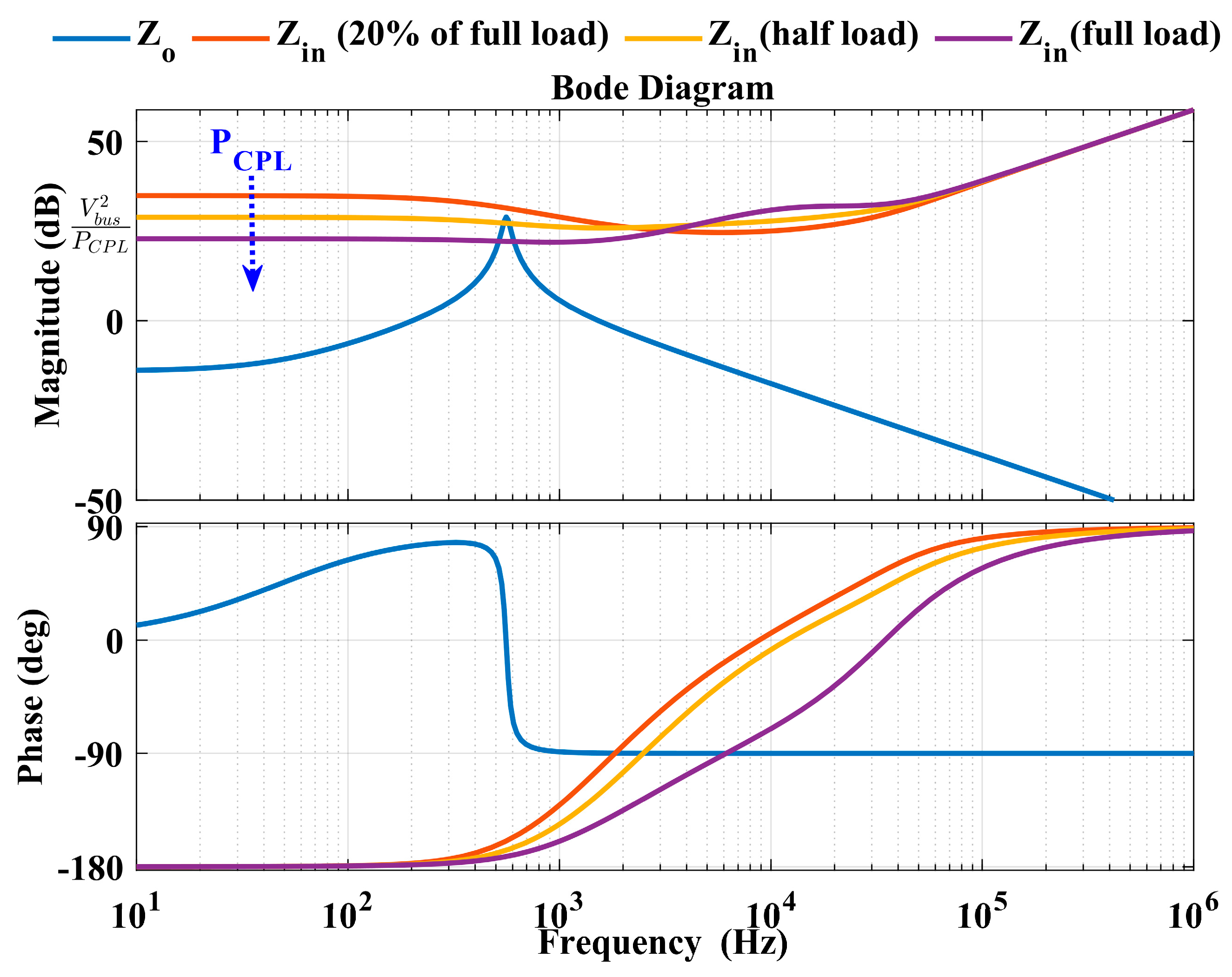
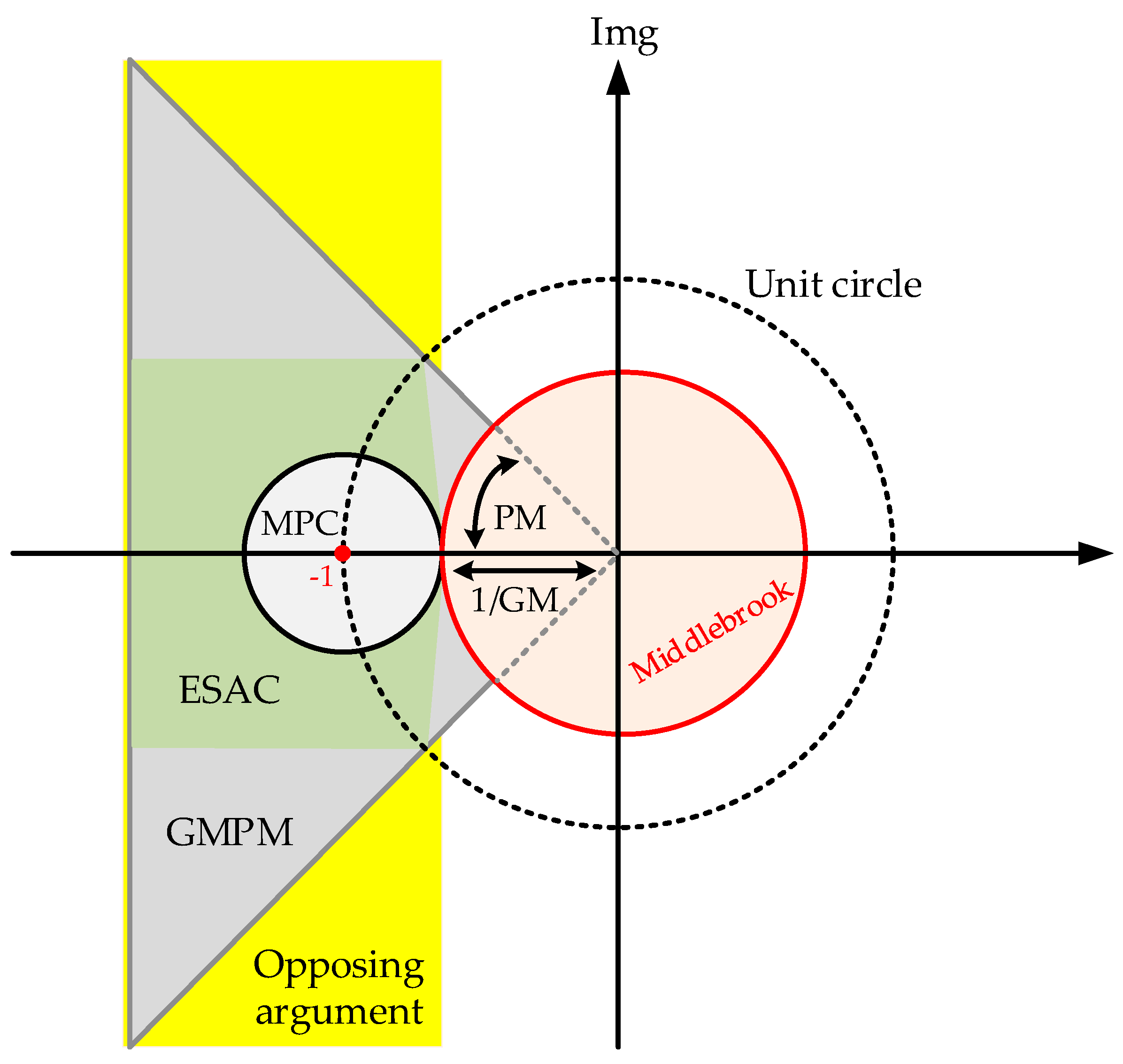
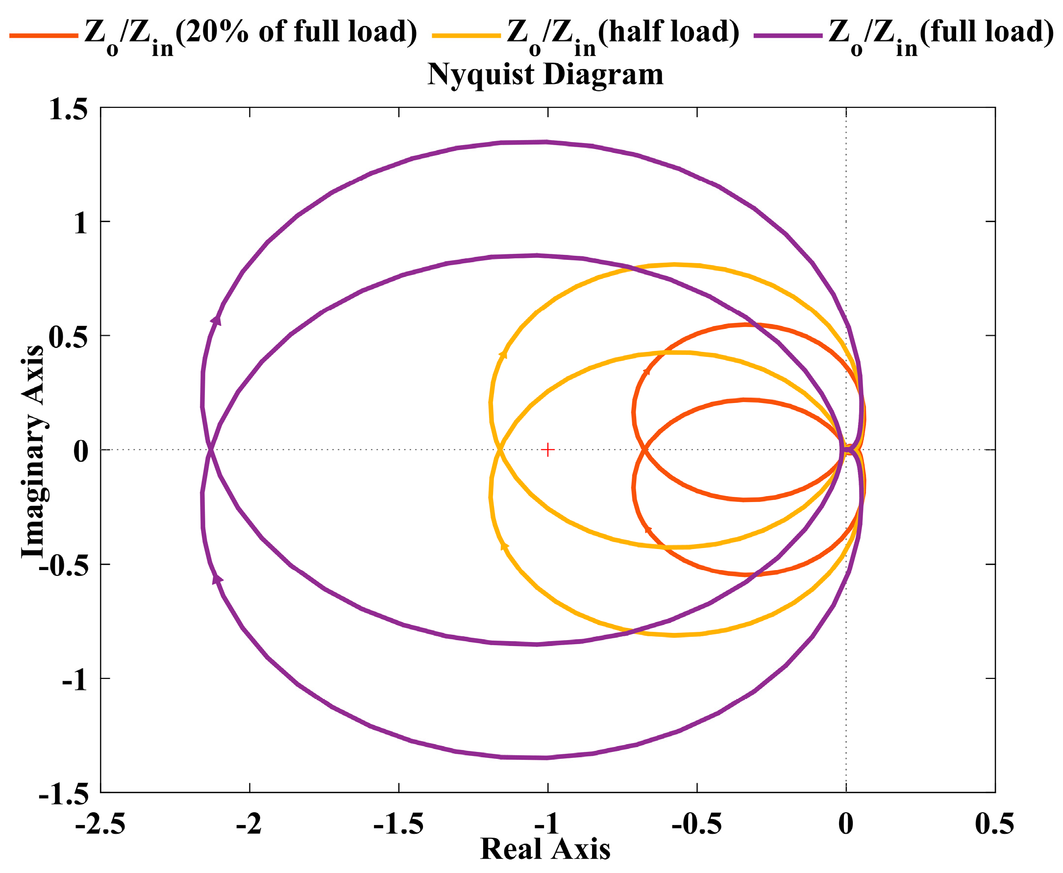
3.3. Impedance Interaction and Stability Analysis

Power electronics converters are often designed and tested separately using just resistive loads [49,50,51]. When an individually designed power converter is cascaded to other circuits, the stability properties of closed-loop converters designed as stand-alone devices are no longer preserved, and the system may exhibit unanticipated dynamic responses [52,53,54,55,56,57,58]. Oscillation in DC bus voltage caused by CPL is depicted in Figure 3b. Because of impedance interactions between the source-side and load-side converters, voltage response oscillations occur.
This impedance interaction occurs when the POL converter’s control loop gain and bandwidth are sufficiently greater than those of the source-side converter [58,59,60]. As a result, regardless of its terminal voltage, the CPL draws constant power from its feeder. The bode diagram of Z i n s and Z o s shown in Figure 4 is plotted by using the parameter given in [61]. Figure 4 can be used to analyse if the amplitude curve of Z o s and Z i n s intersects at a frequency where the phase angle difference is greater than 180°, the system is unstable. In order to ensure the stability of the cascaded system, at least one of the inequalities in (6) should be satisfied.
Z o Z i n 1 φ Z o φ Z i n 180 °  
Various methods have been developed for small-signal stability analysis of the power electronics cascaded system. These methods are based on eigenvalue methods or impedance-based methods [40,62,63,64]. For detailed systematic analysis, the eigenvalue technique is preferred because it has advantages in finding oscillation modes and instability roots of system variables. However, to carry out a stability analysis, it is necessary to have access to all system data, which varies between suppliers and may be kept private [62,63]. In an impedance-based method, a system is separated into a source equivalent and a load equivalent, and system stability is assessed using the Nyquist criteria by comparing the impedance ratios of the source and load. As a result, it is appropriate for examining how different subsystems interact as well as for converter design. The impedance-based method also includes a black box capability, which makes it a powerful tool for online stability study or when system information is unavailable [62]. However, some impedance stability criteria may result in a conservative design due to their conservatism, which makes it difficult to determine the oscillation modes and participation components [40,61,62,63]. As can be seen in Figure 5, numerous stability criteria for DC systems based on forbidden regions for the minor loop gain have been presented in the literature to assess overall system stability. These include the Middlebrook Criterion [46] and its different extensions, such as the gain and phase margin (GMPM) criterion [65], the opposing argument criterion [65,66,67,68], the energy source analysis consortium (ESAC) criterion [69,70] and the maximum peak criterion (MPC) [71,72]. The system stability can be predicted with the help of impedances, by observing the nature of Z o s / Z i n s using the minor loop gain criterion [73,74,75,76]. The cascaded system is stable according to the minor-loop gain criterion, if and only if the Nyquist contour of Z o s / Z i n s does not encircle the critical point (−1, j0) in the complex plain. Figure 6 is plotted by using the parameter given in [61]. From Figure 6, it can be observed that a Nyquist plot of Z o s / Z i n s does not encircle the critical point (−1, j0) at 20% of full load, but it does encircle at half of the full load and at full load.
This stability can be ensured by reshaping either Z o s or Z i n s using the proper stabilization techniques (i.e., passive damping or active damping).

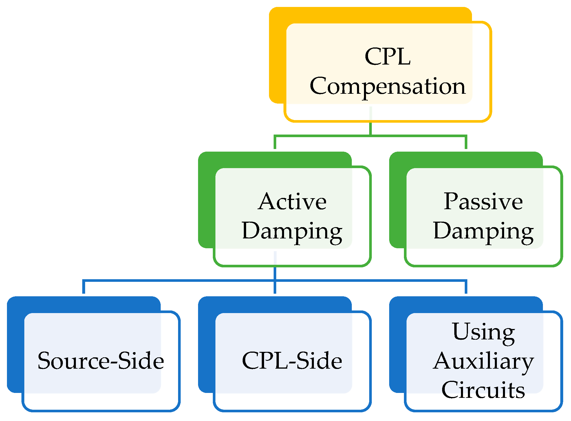
4. Classification of CPL Compensation Techniques

To compensate for the instability caused by CPL connected in cascaded systems, numerous methods have been proposed. These methods essentially rely on two basic concepts: passive damping and active damping as shown in Figure 7.

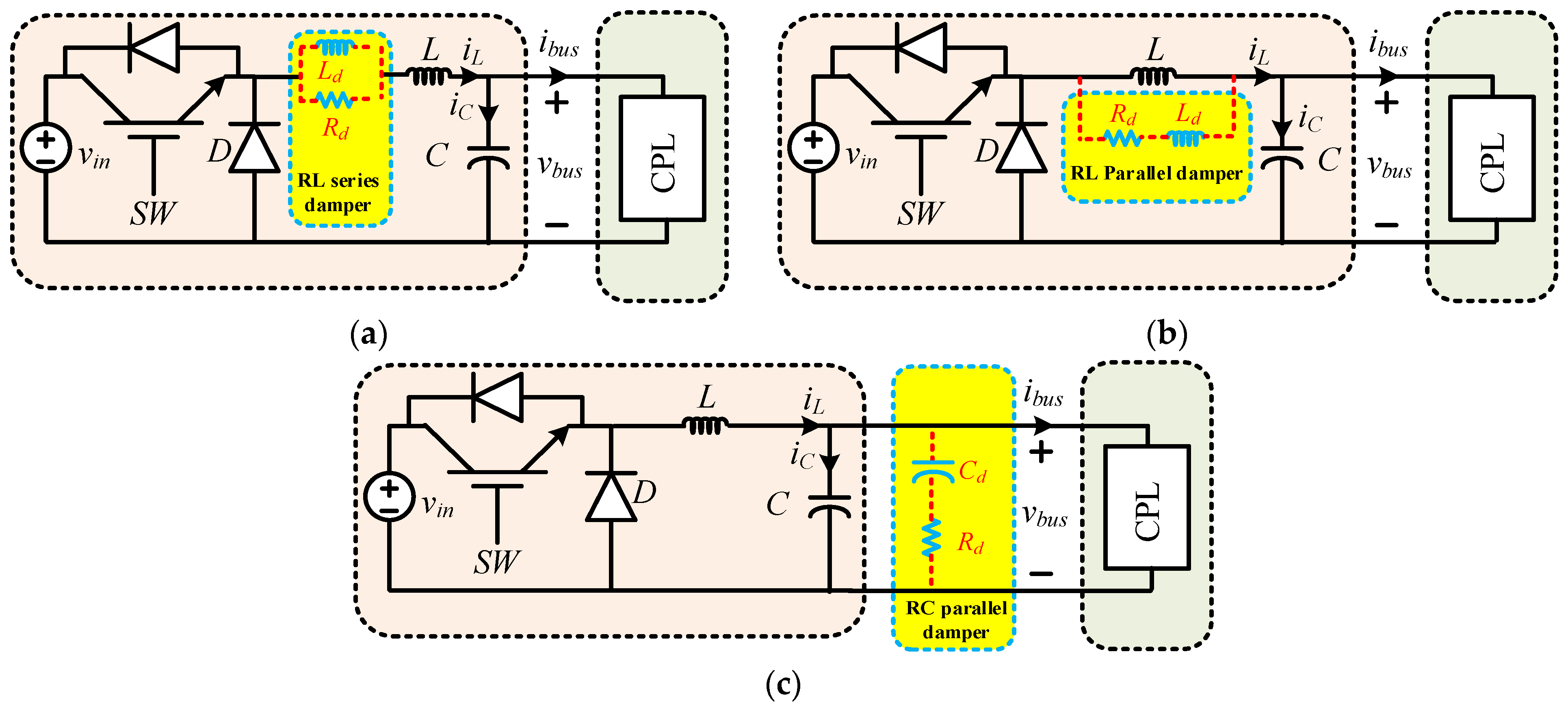
4.1. Passive Damping
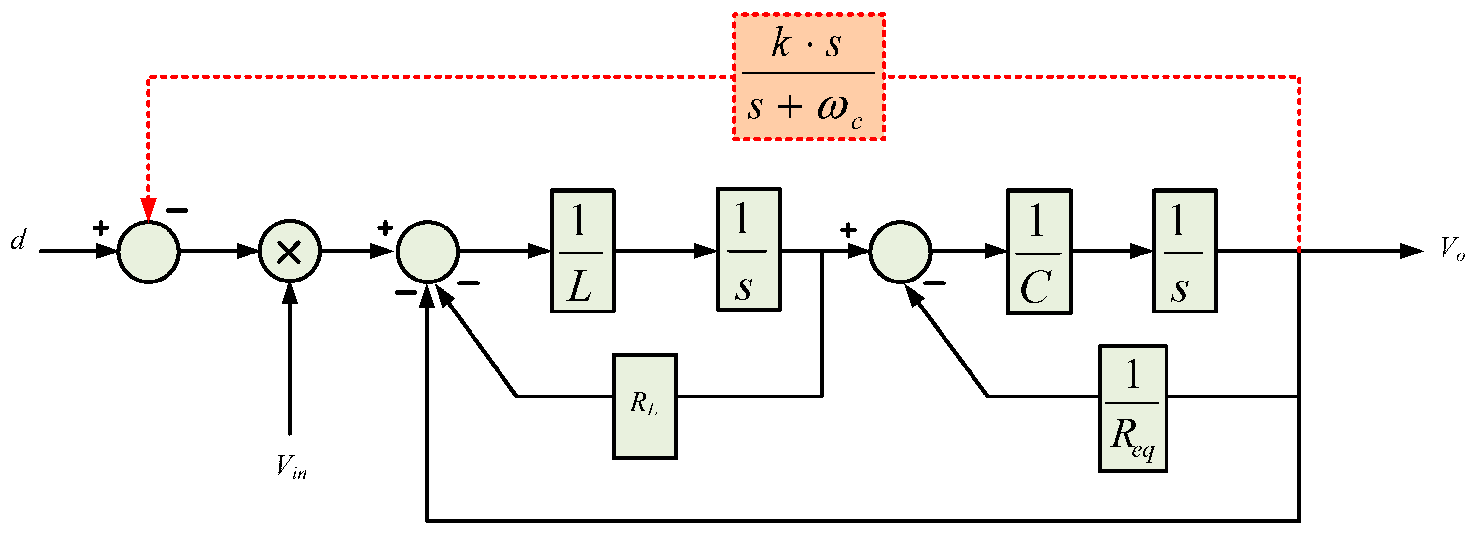
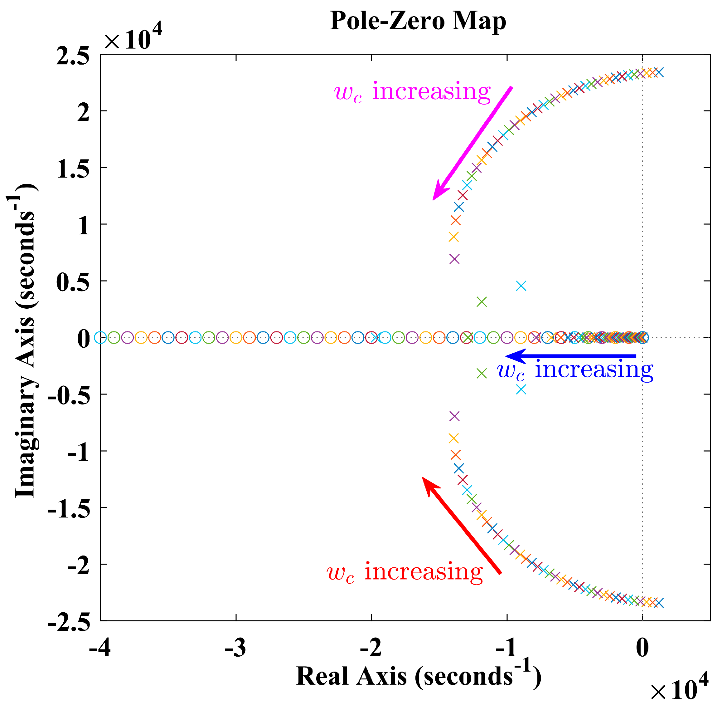
The damping of a system can be improved by adding passive elements such as a resistor (R), an inductor (L) and a capacitor (C), or any combination of these [77,78]. Different types of passive damping stabilization techniques have shown in Figure 8. Adding passive damping to a system is a simple way to increase its damping. The improvement is due to changes in either the cascaded system’s source converter’s output impedance or the load converter’s input impedance. To stabilise the system, the authors of [29] proposed an RC parallel damper to overcome the NII of the CPL and the input LC filter. Moreover, the rise in rated voltage increases the chance of capacitor failure in passive damping [79].
The addition of the damping resistor is a very reliable and effective way to achieve stabilization, but it increases losses in the system and so reduces its energy efficiency [80]. The loss-free resistance (LFR) [81] method may be utilised to decrease power dissipation. The disadvantage of LFR is that it increases the system’s size, complexity and expense.

4.2. Active Damping

Active damping approaches have been developed to address the shortcomings of passive damping. To meet the stability criterion, active damping modifies the control loop of the source side or load side converters [82,83,84]. To increase system stability, active damping can be applied at three distinct zones: source side, CPL side and intermediate level.

4.2.1. Source Side Active Damping

This section summarises source-side active damping implementation via modification in the control loops of the source converter. Active damping at the source side modifies the output impedance of the source converter so that the impedance stability criterion is fulfilled. The major advantage of this method is that the system can be stabilized without affecting the load performance. A virtual RC damper across the converter capacitor is adopted to mitigate the oscillations [24]. Furthermore, an adaptive parallel virtual resistance based on a proportional-derivative load current feedback strategy has been proposed in [53] to mitigate the oscillations. In the controller, the inductor current is used to damp oscillations by creating a virtual resistance in series with the converter inductor [85]. In [86], active damping on the source side has been used to dampen out the oscillation caused by CPLs and the transfer function is given in (7), which is derived from Figure 9. R e q is the equivalent resistance of R and R C P L ( i . e . , R e q = R | | R C P L ) .
V o s d s = V i n L C s 2 + L R e q + R L · C s + 1 + R L R e q
By computing the locations of the pole of (7), we can easily investigate the DC-DC buck converter’s stability.
P 1 , P 2 = L R e q + R L · C ± L R e q + R L · C 2 4 L C 1 + R L R e q 2 L C  
From (8), it can be said that if R e q < 0 and R e q > R L , the system will become unstable because the pole will lie in a right-half plane (RHP). Therefore, one of the LC filter parameters, i.e., R L ,   L , or C , should be correctly modified to fulfil (9).
L R e q < R L · C  
The transfer function given in (10) is derived by implementing the proposed method in [86] as
V o s d s = V i n L C s 3 + L C · ω c + L R e q + R L · C s 2 + B · s + R L R e q · ω c + ω c  
where
B = L R e q · ω c + R L · C · ω c + R L R e q + 1 + k  
We can observe in Figure 10 that by varying damping parameters ω c , poles of the V o s / d s move towards the negative real axis of the s-plane and ensure the stability of the cascaded system [86].

Case study on Source Side Active Damping

In [87], as shown in Figure 11, applying the AD stabiliser loop (red colour) behaves like a dependent voltage source V A D , as shown in Figure 12a. Convert the Thevenin circuit, which includes the voltage source V A D in series with the impedance R L L , to the appropriate Norton equivalent circuit, as illustrated in Figure 12b. As indicated in Figure 12b, dependent current source I A D is moved between nodes x and y, first from node x to node z, then to node y, as illustrated in Figure 12c. The parallel dependent current source to the voltage source can be ignored [24]. Convert the dependent current source to an impedance Z A V R C (Figure 12c) as illustrated in Figure 12d. Referring to Figure 12c, the expression for virtual impedance can be expressed as follows:
Z A V R C = v ^ o I A D = R e q V T r R L K A D V i n s C + L R e q V T r K A D V i n C = 1 s C A V C + R A V R
K A D m i n = V T r V i n   ·   C A V C m i n · R e q · R L C  
where C A V C m i n = C m i n C in that C m i n is calculated by using (9).
The method reported in [87] is easy to tune, adaptive, has less settling time, includes digital delay and provides robust stabilization. However, effectiveness is affected by frequency switching. By using the parameter given in [87], the simulation result has been shown in Figure 13. Up to t = 0.5   s , there is no AD control, so oscillation occurs in the output voltage. At = 0.5   s , AD is enabled and oscillation dampened out, during the change in input voltage and constant power load at = 1   s and at = 1.5   s , respectively. It is observed that in Figure 13, the given method in [87] provides robust stabilization.
The salient features and drawbacks of source-side CPL compensation techniques are summarized in Table 1. Some authors are considering that when CPLs are connected to nearby source-side converters, there is no need for an LC input filter [24,52,85,86]. This is because the source-side converter’s output filter can provide the same function as the LC input filter, which reduces the noise caused by switching. Moreover, some authors are considering a cascaded DC system that comprises a source converter and input filter in series with a load converter [60,88]. Both types of structures are presented in Table 1.

4.2.2. CPL Side Active Damping

When the source side of a cascaded system consists of an LC filter or an uncontrolled converter with no closed loop, active control strategies on the source side cannot be employed to increase system damping [88]. In such circumstances, there are two options for CPL compensation: one is CPL side compensation and the other, use of an active shunt damper between the feeder and the load subsystems. Active damping techniques based on CPL side compensation will be reviewed in this section. To meet Middlebrook’s stability criteria, these techniques adjust the CPL control loops’ input impedance by injecting a compensating current or power. The main issue with this strategy is that the dynamics of the extra compensating loop may disrupt the primary control loop of CPL, resulting in a trade-off between load performance and stability margin. On the other hand, this method is beneficial because CPL itself is used to reduce the negative impedance instabilities. In [93], authors proposed a CPL-side active damping control in which virtual impedance is inserted to damp the oscillation caused by CPL. The cascaded system used in this work is shown in Figure 14. The output impedance of the LC input filter is given in (14) and input impedance can be expressed as (15), where y i n _ o l s , G v d _ o l s , D, T s are the open loop input admittance, control-to-output voltage transfer function, duty cycle and loop gain of the voltage loop of the CPL converter, respectively.
Z o s = s L f + R f s 2 L f C f + s R f C f + 1
Z i n s = y i n o l s 1 + T s P C P L V b u s 2 · T s 1 + T s   1
where
y i n _ o l s = s C L D 2 + D 2 R L d s 2 L L C L + s L L R L d + 1   T s = G C s G P W M G v d _ o l s G v d _ o l s = V b u s s 2 L L C L + s L L R L d + 1  
As we can observe in Figure 4, if the output impedance (i.e., LC input filter) resonance frequency is inside the closed loop bandwidth of the CPL’s input impedance, in such a circumstance, instability occurs beyond the threshold power of the CPL. The threshold power expression is calculated by (17) [60,94].
P t h R f × C f L f × v b u s 2  
A typical DC-coupled hybrid microgrid is reported in the literature [95] as depicted in Figure 15. Because the power consumed from the DC bus is constant for a given AC load, the bidirectional interlinking converter (BIC) appears as CPL to the DC bus during the islanded mode of operation. As a result, voltage oscillation at the DC bus interface of the BIC occurs due to impedance interaction (i.e., Z i p interacts with Z o t ) [96,97]. In [95], a control strategy based on active damping is suggested to address the aforementioned CPL instability without impairing the BIC’s AC voltage regulation performance. However, the implementation of this control method requires six AC sensors, which increases the capital cost of the BIC. The output impedance ( Z o t ) and the input impedance ( Z i p ) can be expressed as follows:
Z o t = s L D C + R D C s 2 L D C C D C + s R D C C D C + 1
Z i p = A s B s i b u s v b u s 1
where
A s = 1.5 [ v d + i d × R f + s L f × ( s C f + 1 / R L ) + i d ] × v d v b u s B s = v b u s [ ( s C f + 1 / R L ) R f + s L f + G C S + G C S G v S ]
The salient features and drawbacks of the CPL side active damping methods are summarized in Table 2.

4.2.3. Using Auxiliary Circuits or Intermediate-Level Active Damping

In this strategy, an extra circuit is added between the source and load subsystems to mitigate the effect of CPLs, while the source and load subsystems remain unchanged. This auxiliary circuit is often a regulated DC-DC converter as seen in Figure 16 that injects the required compensatory current over the entire operating range of the main system [103]. However, this method eliminates the challenges of the previous two approaches (i.e., source side and CPL side). While it increases the overall complexity of the system, it also imposes additional cost and power losses. In [104], the authors proposed an auxiliary circuit active damping method which is connected to the output of the load side converter as depicted in Figure 17. It improves the transient performance of the cascaded system. However, the implementation is complex and also imposes an extra cost.

5. The Delays in Digitally Controlled Systems and Their Effect on Active Damping Control

Implementation of the AD techniques in the digital domain is an important practical aspect that needs to be taken care of. The control system in the digital platform consists of two types of delays: computational delay and pulse width modulation (PWM) delay [24,105,106,107]. As synchronous sampling is frequently employed in digitally controlled systems; the computation delay is represented by the interval of time T s between two samples, which is expressed as
G d , C O M = e s T s  
The PWM delay may be due to zero-order hold (ZOH), which is expressed as [105]
G d , P W M s = 1 e s T s s  
G d , P W M s can be expressed in the frequency domain as (23)
G d , P W M j ω = 1 e j ω T s j ω = sin 0.5 ω T s 0.5 ω e j 0.5 ω T s T s e j 0.5 ω T s
From (23), G d , P W M s   T s e 0.5 s T s , which may be responsible for the delay of half of the sample time. These delay effects are incorporated in the control loop of the digitally controlled converter by cascading Z O H (for PWM delay) and Z 1 (for computational delay) blocks. By combining the abovementioned delays, the net delay in the digital control system can be considered as e 1.5 s T s   . The bode plot of the open-loop gain V ^ o s / d ^ s of a buck converter with the parameters given in [87] is shown in Figure 18, where, K A D is the gain of the active damping controller and its minimum value (i.e., K A D min ) is calculated by using (13). In Figure 18a, for K A D min , the system is approaching the marginal stability scenario. Increasing K A D improves the phase margin of the system, indicating an increase in system damping as shown in Figure 18a. In this way, the stability of the closed-loop control system is ascertained. Figure 18b shows that, while considering computational and modulation delays, increasing K A D by a specific amount gradually reduces the system’s phase margin until the system becomes unstable. This implies that K A D must have a stable range between K A D min ,   K A D m a x . The stable range of K A D can also be increased by decreasing T s . K A D m a x can be easily calculated by solving the (24) and (25) [21,107]:
e j ω T s G s = π  
e j ω T s G s = 1  
G s = V ^ b u s s d ^ s | o p e n l o o p = e j 0.5 ω T s · E q u a t i o n   7 · G P I s G A D s
where G A D s is the resulting active damping gain and G P I s is the PI controller ( i . e . ,   K p + K I / s )
The delay-induced phase lag effect reduces the phase margin in the high-frequency region. However, because of the minimal quantity of T s , the delay in the low-frequency zone has no effect and only restricts the upper band of K A D to a certain value. Figure 18b shows a significant flexibility in selecting an appropriate damping gain K A D , which may change based on the designer’s viewpoint. To provide the system roboustness under abrupt changes in input voltage and load, K A D should be much larger than K A D m i n   (i.e., 15 to 20 times of K A D m i n ) .

6. Challenges and Future Research Directions

This article contributes to the prospects of the various stabilization techniques for cascaded systems in DC microgrids based on the active damping approach. The benefits and drawbacks of various active damping approaches have been discussed extensively in the preceding sections. This section summarises the overall findings of this review work as well as recommendations for future work.
Load-side active damping: Active control strategies on the source side cannot be used to increase the system damping when the source side is an LC filter or an uncontrolled converter in a cascaded system. In these situations, CPL-side compensation is a viable choice. However, the main issue with this strategy is that the dynamics of the extra compensating loop may disrupt the primary control loop of the CPL, resulting in a trade-off between load performance and stability margin.
Source-side active damping: This method’s major advantage is that the system can be stabilized without affecting load performance. However, it is not applicable when the source converter operates in an open loop.
Intermediate-level active damping: In this strategy, an extra circuit is added between the source and load subsystems to mitigate the destabilizing effect of CPLs, while the source and load subsystems remain unchanged. However, this method eliminates the challenges of the previous two approaches (i.e., source-side and CPL-side). While it increases the system’s overall complexity, it also imposes additional costs and power losses.
From the above explanation in Table 1 and Table 2, it can be inferred that each damping control technique has merits and drawbacks. The recommendations are as follows.
  • An investigation of the generalization of active stabilizing techniques is required for the complex DC MGs. Moreover, the stability issues for DC MGs in the presence of dynamic loads and CPLs need to be addressed.
  • The linear active damping techniques are operating point-dependent and can compensate only a limited amount of CPL. Therefore, non-linear damping techniques can be investigated to address the above problem.
  • Further, the tuning parameters of active damping techniques are converter-dependent and they would vary from one converter to another. Thus, converter-free active damping techniques need to be developed to address the problems of converter dependence.
  • The performance of damping techniques depends on converters and the modelling of the complex system and the perfect design of parameters. Therefore, to make model-free stabilization, one can look into data-driven control techniques to improve the stability of the DC MGs.
  • In a more complicated DC network with several source converters, interactions between their control loops have an impact on the converter performance. Therefore, the modelling and stability analysis of the much more practical systems, e.g., multi-terminal DC MG with CPL, is required to investigate.
  • Research on the optimal placement of CPL (e.g., fast DC chargers for EVs) is further required to ensure the stability of the DC MGs, a practical scenario in an EV parking lot with incoming and outgoing EVs.
  • When addressing the effects of CPL in cascaded systems, the majority of active damping techniques focused on small-signal stability, which can only ensure stability for small disturbances. However, the system under large disturbances is also important. Thus, further exploration with large-signal stability is required to ensure the global stability of the system over a wide dynamic range.
  • Based on the observations above, we can conclude that the majority of the work is based on a cascaded DC-DC converter system. However, there has been very little work with cascaded DC–AC converter systems or in islanded MGs. Future research is still needed.
  • Finally, research that aims to reduce the number of sensors, controller order and implementation complexity is required.

7. Conclusions

This paper has presented a comprehensive review of the active damping stabilization method for cascaded systems in DC microgrids. Because of the negative impedance properties of CPLs, oscillation occurs in voltage response at DC bus. Therefore, a reliable control system is essential. Thus, this paper focuses on active damping control techniques. First, this paper discussed the CPL modelling and the analysis of cascaded systems in DC MGs. Furthermore, classification of CPL compensation techniques and their merits and drawbacks was summarized. It is envisaged that it would be useful, directing researchers in the appropriate path for developing damping stabilisation in DC microgrids. More research on active approaches is required in the future to increase the dynamics and robustness of the cascaded system.

Author Contributions

Conceptualization, R.K. and C.N.B.; methodology, R.K. and C.N.B.; software, R.K.; validation, R.K. and C.N.B.; formal analysis, R.K.; investigation, R.K. and C.N.B.; resources, R.K.; data curation, R.K.; writing—original draft preparation, R.K.; writing—review and editing, R.K. and C.N.B.; visualization, R.K. and C.N.B.; supervision, C.N.B.; project administration, R.K. and C.N.B.; funding acquisition, C.N.B. All authors have read and agreed to the published version of the manuscript.

Funding

This research received no external funding.

Data Availability Statement

Not applicable.

Conflicts of Interest

The authors declare no conflict of interest.

Nomenclature

A D Active damping
D G M G s Direct Current microgrids
C P L Constant power load
E V sElectric vehicles
P O L Point of load converter
D O E Department of Energy
Z O H Zero-order hold
A D Active damping
M G s Microgrids
R E G Renewable energy generation
S S V I Source-side series virtual impedance
L S V I Load-side series virtual impedance
L P V I Load-side parallel virtual impedance
A S V I Adaptive series virtual impedance
A P V I Adaptive parallel virtual impedance
L P F Low pass filter
H P F High pass filter
B P F Bandpass filter
K A D Gain of active damping
L V D C Low voltage direct current
P W M Pulse width modulation
M E G Microgrid exchange group
M E A more electric aircraft
N I I negative incremental impedance
G M P M Gain and phase margin
E S A C Energy source analysis consortium
M P C Maximum peak criterion
L F R Loss-free resistance
A A C C Adaptive active capacitor converter

References

  1. Fotopoulou, M.; Rakopoulos, D.; Trigkas, D.; Stergiopoulos, F.; Blanas, O.; Voutetakis, S. State of the Art of Low and Medium Voltage Direct Current (DC) Microgrids. Energies 2021, 14, 5595. [Google Scholar] [CrossRef]
  2. Abraham, D.S.; Verma, R.; Kanagaraj, L.; Giri Thulasi Raman, S.R.; Rajamanickam, N.; Chokkalingam, B.; Sekar, K.M.; Mihet-Popa, L. Electric Vehicles Charging Stations’ Architectures, Criteria, Power Converters, and Control Strategies in Microgrids. Electronics 2021, 10, 1895. [Google Scholar] [CrossRef]
  3. Al-Ismail, F. DC Microgrid Planning, Operation, and Control: A Comprehensive Review. IEEE Access 2021, 9, 36154–36172. [Google Scholar] [CrossRef]
  4. Dragicevic, T.; Lu, X.; Vasquez, J.; Guerrero, J. DC Microgrids—Part I: A Review of Control Strategies and Stabilization Techniques. IEEE Trans. Power Electron. 2015, 31, 4876–4891. [Google Scholar] [CrossRef] [Green Version]
  5. Dragičević, T.; Wheeler, P.; Blaabjerg, F. DC Distribution Systems and Microgrids; IET: Stevenage, UK, 2018. [Google Scholar]
  6. Han, Y.; Ning, X.; Yang, P.; Xu, L. Review of Power Sharing, Voltage Restoration and Stabilization Techniques in Hierarchical Controlled DC Microgrids. IEEE Access 2019, 7, 149202–149223. [Google Scholar] [CrossRef]
  7. Smith, M.; Ton, D. Key Connections: The U.S. Department of Energy’s Microgrid Initiative. IEEE Power Energy Mag. 2013, 11, 22–27. [Google Scholar] [CrossRef]
  8. Gries, M.; Wasynczuk, O.; Selby, B.; Lamm, P. Designing for Large-Displacement Stability in Aircraft Power Systems. SAE Int. J. Aerosp. 2008, 1, 894–902. [Google Scholar] [CrossRef]
  9. Mukherjee, N.; Strickland, D. Control of Cascaded DC-DC Converter Based Hybrid Battery Energy Storage Systems: Part—I: Stability Issue. IEEE Trans. Ind. Electron. 2015, 63, 2340–2349. [Google Scholar] [CrossRef] [Green Version]
  10. Julian, A.; Cuzner, R. Design, Modelling and Stability Analysis of an Integrated Shipboard DC Power System. In Proceedings of the 2009 IEEE Electric Ship Technologies Symposium, Baltimore, MD, USA, 20–22 April 2009. [Google Scholar]
  11. Smithson, S.; Williamson, S. Constant Power Loads in More Electric Vehicles—An Overview. In Proceedings of the IECON 2012—38th Annual Conference on IEEE Industrial Electronics Society, Montreal, QC, Canada, 25–28 October 2012. [Google Scholar]
  12. Krein, P. Data Center Challenges and Their Power Electronics. CPSS Trans. Power Electron. Appl. 2017, 2, 39–46. [Google Scholar] [CrossRef]
  13. Kumar, D.; Zare, F.; Ghosh, A. DC Microgrid Technology: System Architectures, AC Grid Interfaces, Grounding Schemes, Power Quality, Communication Networks, Applications, and Standardizations Aspects. IEEE Access 2017, 5, 12230–12256. [Google Scholar] [CrossRef]
  14. Bhargavi, K.; Jayalakshmi, N.; Gaonkar, D.; Shrivastava, A.; Jadoun, V. A Comprehensive Review on Control Techniques for Power Management of Isolated DC Microgrid System Operation. IEEE Access 2021, 9, 32196–32228. [Google Scholar] [CrossRef]
  15. Garcés, A. Modeling, Operation, and Analysis of DC Grids: From High Power DC Transmission to DC Microgrids; Academic Press: San Diego, CA, USA, 2021. [Google Scholar]
  16. Singh, S.; Gautam, A.; Fulwani, D. Constant power loads and their effects in DC distributed power systems: A review. Renew. Sustain. Energy Rev. 2017, 72, 407–421. [Google Scholar] [CrossRef]
  17. Shafiee, Q.; Dragicevic, T.; Vasquez, J.; Guerrero, J. Modeling, Stability Analysis and Active Stabilization of Multiple DC-Microgrid Clusters. In Proceedings of the 2014 IEEE International Energy Conference (ENERGYCON), Cavtat, Croatia, 13–16 May 2014. [Google Scholar]
  18. Emadi, A.; Khaligh, A.; Rivetta, C.; Williamson, G. Constant Power Loads and Negative Impedance Instability in Automotive Systems: Definition, Modeling, Stability, and Control of Power Electronic Converters and Motor Drives. IEEE Trans. Veh. Technol. 2006, 55, 1112–1125. [Google Scholar] [CrossRef]
  19. Bottrell, N.; Prodanovic, M.; Green, T. Dynamic Stability of a Microgrid with an Active Load. IEEE Trans. Power Electron. 2013, 28, 5107–5119. [Google Scholar] [CrossRef] [Green Version]
  20. Liang, H.; Liu, Z.; Liu, H. Stabilization Method Considering Disturbance Mitigation for DC Microgrids with Constant Power Loads. Energies 2019, 12, 873. [Google Scholar] [CrossRef] [Green Version]
  21. Ahmadi, R. Dynamic Modeling, Stability Analysis, and Controller Design for DC Distribution Systems. Ph.D. Thesis, Missouri University of Science and Technology, Rolla, MO, USA, 2013. [Google Scholar]
  22. Riccobono, A.; Santi, E. Comprehensive Review of Stability Criteria for DC Power Distribution Systems. IEEE Trans. Ind. Appl. 2014, 50, 3525–3535. [Google Scholar] [CrossRef]
  23. Hossain, E.; Perez, R.; Nasiri, A.; Padmanaban, S. A Comprehensive Review on Constant Power Loads Compensation Techniques. IEEE Access 2018, 6, 33285–33305. [Google Scholar] [CrossRef]
  24. Lorzadeh, O.; Lorzadeh, I.; Soltani, M.; Hajizadeh, A. Source-Side Virtual RC Damper-Based Stabilization Technique for Cascaded Systems in DC Microgrids. IEEE Trans. Energy Convers. 2021, 36, 1883–1895. [Google Scholar] [CrossRef]
  25. Hussain, M.; Agarwal, V. A Novel Feedforward Stabilizing Technique to Damp Power Oscillations Caused by DC-DC Converters Fed from a DC Bus. IEEE J. Emerg. Sel. Top. Power Electron. 2020, 8, 1528–1535. [Google Scholar] [CrossRef]
  26. Emadi, A.; Fahimi, B.; Ehsani, M. On the concept of negative impedance instability in the more electric aircraft power systems with constant power loads. SAE Trans. 1999, 108, 689–699. [Google Scholar]
  27. Griffo, A.; Wang, J. Modeling and stability analysis of hybrid power systems for the more electric aircraft. Electr. Power Syst. Res. 2012, 82, 59–67. [Google Scholar] [CrossRef]
  28. Zhang, F.; Yan, Y. Start-up process and step response of a DC-DC converter loaded by constant power loads. IEEE Trans. Ind. Electron. 2011, 58, 298–304. [Google Scholar] [CrossRef]
  29. Jusoh, A.B. The Instability Effect of Constant Power Loads. In Proceedings of the PECon 2004. Proceedings. National Power and Energy Conference, Kuala Lumpur, Malaysia, 29–30 November 2004. [Google Scholar]
  30. Zamierczuk, M.K.; Cravens, R.C.; Reatti, A. Closed-Loop Input Impedance of PWM Buck-Derived DC-DC Converters. In Proceedings of the Proceedings of IEEE International Symposium on Circuits and Systems—ISCAS’94, London, UK, 30 May–2 June 1994. [Google Scholar]
  31. Rivetta, C.; Williamson, G.A.; Emadi, A. Constant Power Loads and Negative Impedance Instability in Sea and Undersea Vehicles: Statement of the Problem and Comprehensive Large-Signal Solution. In Proceedings of the IEEE Electric Ship Technologies Symposium, 2005, Philadelphia, PA, USA, 27 July 2005. [Google Scholar]
  32. Kim, S.; Williamson, S. Negative Impedance Instability Compensation in More Electric Aircraft DC Power Systems Using State Space Pole Placement Control. In Proceedings of the 2011 IEEE Vehicle Power and Propulsion Conference 2011, Chicago, IL, USA, 6–9 September 2011. [Google Scholar]
  33. Liu, X.; Zhou, Y.; Zhang, W.; Ma, S. Stability Criteria for Constant Power Loads with Multistage LC Filters. IEEE Trans. Veh. Technol. 2011, 60, 2042–2049. [Google Scholar] [CrossRef]
  34. Emadi, A.; Ehsani, M.; Miller, J.M. Vehicular Electric Power Systems: Land, Sea, Air, and Space Vehicles; CRC Press: Boca Raton, FL, USA, 2003. [Google Scholar]
  35. AL-Nussairi, M.; Bayindir, R.; Padmanaban, S.; Mihet-Popa, L.; Siano, P. Constant Power Loads (CPL) with Microgrids: Problem Definition, Stability Analysis and Compensation Techniques. Energies 2017, 10, 1656. [Google Scholar] [CrossRef]
  36. Emadi, A.; Ehsani, M. Negative Impedance Stabilizing Controls for PWM DC-DC Converters Using Feedback Linearization Techniques. In Proceedings of the Collection of Technical Papers. 35th Intersociety Energy Conversion Engineering Conference and Exhibit (IECEC) (Cat. No.00CH37022), Las Vegas, NV, USA, 24–28 July 2000. [Google Scholar]
  37. Rivetta, C.; Emadi, A.; Williamson, G.; Jayabalan, R.; Fahimi, B. Analysis and control of a buck DC-DC converter operating with constant power load in sea and undersea vehicles. IEEE Trans. Ind. Appl. 2006, 42, 559–572. [Google Scholar] [CrossRef]
  38. Ahmadi, R.; Paschedag, D.; Ferdowsi, M. Analyzing stability issues in a cascaded converter system comprised of two voltage-mode controlled dc-dc converters. In Proceedings of the 2011 Twenty-Sixth Annual IEEE Applied Power Electronics Conference and Exposition (APEC), Fort Worth, TX, USA, 6–11 March 2011. [Google Scholar]
  39. Khaligh, A.; Rahimi, A.; Chakraborty, A.; Emadi, A. Analysis and Stabilization of a Buck-Boost DC-DC Converter Feeding Constant Power Loads in Parallel with Conventional Loads in Vehicular Systems. In Proceedings of the IECON 2006—32nd Annual Conference on IEEE Industrial Electronics, Paris, France, 6–10 November 2006. [Google Scholar]
  40. Vesti, S.; Oliver, J.; Prieto, R.; Cobos, J.; Suntio, T. Simplified Small-Signal Stability Analysis for Optimized Power System Architecture. In Proceedings of the 2013 Twenty-Eighth Annual IEEE Applied Power Electronics Conference and Exposition (APEC), Long Beach, CA, USA, 17–21 March 2013. [Google Scholar]
  41. Basso, C.P. Designing Control Loops for Linear and Switching Power Supplies: A Tutorial Guide; Artech House: Norwood, MA, USA, 2012. [Google Scholar]
  42. Suntio, T. Dynamic Profile of Switched-Mode Converter: Modeling, Analysis and Control; Wiley-VCH: Weinheim, Germany, 2009. [Google Scholar]
  43. Hassan, M.; Su, C.-L.; Chen, F.-Z.; Lo, K.-Y. Adaptive passivity-based control of a DC-DC boost power converter supplying constant power and constant voltage loads. IEEE Trans. Ind. Electron. 2022, 69, 6204–6214. [Google Scholar] [CrossRef]
  44. Hassan, M.A.; Su, C.-L.; Pou, J.; Sulligoi, G.; Almakhles, D.; Bosich, D.; Guerrero, J.M. DC shipboard microgrids with constant power loads: A review of Advanced Nonlinear Control Strategies and Stabilization Techniques. IEEE Trans. Smart Grid 2022, 13, 3422–3438. [Google Scholar] [CrossRef]
  45. Tian, Y.; Loh, P.; Chen, Z.; Deng, F.; Hu, Y. Impedance interactions in bidirectional cascaded converter. IET Power Electron. 2016, 9, 2482–2491. [Google Scholar] [CrossRef]
  46. Middlebrook, R.D. Input Filter Considerations in Design and Application of Switching Regulators. IEEE Ind. Appl. Soc. Annu. Meet. 1976, IA-12, 366–382. [Google Scholar]
  47. Li, P.; Lehman, B. Performance prediction of DC-DC converters with impedances as loads. IEEE Trans. Power Electron. 2004, 19, 201–209. [Google Scholar] [CrossRef]
  48. Pidaparthy, S.; Choi, B. Control Design and Loop Gain Analysis of DC-to-DC Converters Intended for General Load Subsystems. Math. Probl. Eng. 2015, 2015, 426315. [Google Scholar] [CrossRef] [Green Version]
  49. Mayo-Maldonado, J.; Ruiz-Martinez, O.; Escobar, G.; Maupong, T.; Valdez-Resendiz, J.; Rosas-Caro, J. Power shaping control of DC-DC converters with constant power loads. Control Eng. Pract. 2020, 105, 104639. [Google Scholar] [CrossRef]
  50. Erickson, R.W.; Dragan, M. Fundamentals of Power Electronics; Kluwer Academic: Norwell, MA, USA, 2001. [Google Scholar]
  51. Pourmohammad, M.; Toulabi, M.; Rayati, M.; Khajehoddin, S. Load type impacts on the stability and robustness of DC microgrids. Int. J. Electr. Power & Energy Syst. 2022, 140, 108036. [Google Scholar] [CrossRef]
  52. Lorzadeh, O.; Lorzadeh, I.; Soltani, M.; Hajizadeh, A.; Jessen, K. Active Load Stabilization of Cascaded Systems in DC Microgrids Using Adaptive Parallel-Virtual-Resistance Control Scheme. IEEE J. Emerg. Sel. Top. Power Electron. 2021. [Google Scholar] [CrossRef]
  53. Emadi, A.; Ehsani, M. Multi-Converter Power Electronic Systems: Definition and Applications. In Proceedings of the 2001 IEEE 32nd Annual Power Electronics Specialists Conference (IEEE Cat. No.01CH37230), Vancouver, BC, Canada, 17–21 June 2001. [Google Scholar]
  54. Khaligh, A.; Emadi, A.; Williamson, G.A.; Rivetta, C. Constant Power Load Characteristics in Multi-Converter Automotive Power Electronic Intensive Systems; SAE Technical Paper 2005-01-3451; SAE International: Warrendale, PA, USA, 2005. [Google Scholar]
  55. Khaligh, A.; Emadi, A. Power Alignment, New Digital Control Approach for a DC-DC Flyback Converter with Constant Power Loads. In Proceedings of the 2006 1ST IEEE Conference on Industrial Electronics and Applications, Singapore, 24–26 May 2006. [Google Scholar]
  56. Tahim, A.; Pagano, D.; Lenz, E.; Stramosk, V. Modeling and Stability Analysis of Islanded DC Microgrids Under Droop Control. IEEE Trans. Power Electron. 2015, 30, 4597–4607. [Google Scholar] [CrossRef]
  57. Herrera, L.C.; Tsao, B.-H. Analysis and control of energy storage in aircraft power systems with pulsed power loads. SAE Int. J. Aerosp. 2016, 9, 8–13. [Google Scholar] [CrossRef]
  58. Ansari, S.; Zhang, J.; Singh, R. A review of stabilization methods for DCMG with CPL, the role of bandwidth limits and droop control. Prot. Control Mod. Power Syst. 2022, 7, 2. [Google Scholar] [CrossRef]
  59. Hankaniemi, M. Dynamical Profile of Switched-Mode Converter—Fact or Fiction? Ph.D. Thesis, Tampere University of Technology, Tampere, Finland, 2007. [Google Scholar]
  60. Hussain, M.; Mishra, R.; Agarwal, V. A Frequency-Dependent Virtual Impedance for Voltage-Regulating Converters Feeding Constant Power Loads in a DC Microgrid. IEEE Trans. Ind. Appl. 2018, 54, 5630–5639. [Google Scholar] [CrossRef]
  61. Wu, M.; Lu, D.; Tse, C. Direct and Optimal Linear Active Methods for Stabilization of LC Input Filters and DC/DC Converters Under Voltage Mode Control. IEEE J. Emerg. Sel. Top. Circuits Syst. 2015, 5, 402–412. [Google Scholar] [CrossRef]
  62. Blaabjerg, F. Control of Power Electronic Converters and Systems; Academic Press: Amsterdam, The Netherlands, 2021. [Google Scholar]
  63. Sun, J. Small-signal methods for AC Distributed Power Systems—A Review. IEEE Trans. Power Electron. 2009, 24, 2545–2554. [Google Scholar]
  64. Wang, Y.; Wang, X.; Chen, Z.; Blaabjerg, F. Small-Signal Stability Analysis of inverter-fed power systems using component connection method. IEEE Trans. Smart Grid 2018, 9, 5301–5310. [Google Scholar] [CrossRef] [Green Version]
  65. Wildrick, C.M.; Lee, F.C.; Cho, B.H.; Choi, B. A method of defining the load impedance specification for a stable distributed power system. IEEE Trans. Power Electron. 1995, 10, 280–285. [Google Scholar] [CrossRef]
  66. Feng, X.; Ye, Z.; Xing, K.; Lee, F.C.; Borojevic, D. Impedance Specification and Impedance Improvement for DC Distributed Power System. In Proceedings of the 30th Annual IEEE Power Electronics Specialists Conference. Record. (Cat. No.99CH36321), Charleston, SC, USA, 1 July 1999. [Google Scholar]
  67. Feng, X.; Ye, Z.; Xing, K.; Lee, F.C.; Borojevic, D. Individual Load Impedance Specification for a Stable DC Distributed Power System. In Proceedings of the APEC’99. Fourteenth Annual Applied Power Electronics Conference and Exposition. 1999 Conference Proceedings (Cat. No.99CH36285), Dallas, TX, USA, 14–18 March 1999. [Google Scholar]
  68. Feng, X.; Liu, J.; Lee, F.C. Impedance specifications for stable DC distributed Power Systems. IEEE Trans. Power Electron. 2002, 17, 157–162. [Google Scholar] [CrossRef]
  69. Sudhoff, S.D.; Glover, S.F.; Lamm, P.T.; Schmucker, D.H.; Delisle, D.E. Admittance space stability analysis of power electronic systems. IEEE Trans. Aerosp. Electron. Syst. 2000, 36, 965–973. [Google Scholar] [CrossRef]
  70. Sudhoff, S.D.; Glover, S.F. Three-Dimensional Stability Analysis of DC Power Electronics Based Systems. In Proceedings of the 2000 IEEE 31st Annual Power Electronics Specialists Conference. Conference Proceedings (Cat. No.00CH37018), Galway, Ireland, 23 June 2000. [Google Scholar]
  71. Vesti, S.; Suntio, T.; Oliver, J.A.; Prieto, R.; Cobos, J.A. Effect of control method on impedance-based interactions in a buck converter. IEEE Trans. Power Electron. 2013, 28, 5311–5322. [Google Scholar] [CrossRef] [Green Version]
  72. Suntio, T.; Messo, T.; Berg, M.; Alenius, H.; Reinikka, T.; Luhtala, R.; Zenger, K. Impedance-Based Interactions in Grid-Tied Three-Phase Inverters in Renewable Energy Applications. Energies 2019, 12, 464. [Google Scholar] [CrossRef] [Green Version]
  73. Zhang, X.; Ruan, X.; Tse, C. Impedance-Based Local Stability Criterion for DC Distributed Power Systems. IEEE Trans. Circuits Syst. I Regul. Pap. 2015, 62, 916–925. [Google Scholar] [CrossRef]
  74. Fang, J.; Shuai, Z.; Li, Y.; Wang, Z.; Wu, X.; Shen, X.; Shen, Z.J. Stability Investigation and Improvement for DC Cascade Systems with Simplified Impedance-Based Stability Criterion. CSEE J. Power Energy Syst. 2022. [Google Scholar] [CrossRef]
  75. Du, W.; Zhang, J.; Zhang, Y.; Qian, Z. Stability Criterion for Cascaded System with Constant Power Load. IEEE Trans. Power Electron. 2013, 28, 1843–1851. [Google Scholar] [CrossRef]
  76. Dragicevic, T. Dynamic Stabilization of DC Microgrids with Predictive Control of Point-of-Load Converters. IEEE Trans. Power Electron. 2018, 33, 10872–10884. [Google Scholar] [CrossRef] [Green Version]
  77. Cespedes, M.; Xing, L.; Sun, J. Constant-Power Load System Stabilization by Passive Damping. IEEE Trans. Power Electron. 2011, 26, 1832–1836. [Google Scholar] [CrossRef]
  78. Erickson, R. Optimal Single Resistors Damping of Input Filters. In Proceedings of the APEC’99. Fourteenth Annual Applied Power Electronics Conference and Exposition. 1999 Conference Proceedings (Cat. No.99CH36285), Dallas, TX, USA, 14–18 March 1999. [Google Scholar]
  79. Wang, H.; Blaabjerg, F. Reliability of Capacitors for DC-Link Applications in Power Electronic Converters—An Overview. IEEE Trans. Ind. Appl. 2014, 50, 3569–3578. [Google Scholar] [CrossRef] [Green Version]
  80. Rahimi, A.; Emadi, A. An Analytical Investigation of DC/DC Power Electronic Converters with Constant Power Loads in Vehicular Power Systems. IEEE Trans. Veh. Technol. 2009, 58, 2689–2702. [Google Scholar] [CrossRef]
  81. Singer, S. Realization of loss-free resistive elements. IEEE Trans. Circuits Syst. 1990, 37, 54–60. [Google Scholar] [CrossRef]
  82. Radwan, A.; Mohamed, Y. Linear Active Stabilization of Converter-Dominated DC Microgrids. IEEE Trans. Smart Grid 2012, 3, 203–216. [Google Scholar] [CrossRef]
  83. Lee, J.-S.; Choi, Y.-J. A Stability Improvement Method of DC Microgrid System Using Passive Damping and Proportional-Resonance (PR) Control. Sustainability 2021, 13, 9542. [Google Scholar] [CrossRef]
  84. Lu, X.; Sun, K.; Guerrero, J.; Vasquez, J.; Huang, L.; Wang, J. Stability Enhancement Based on Virtual Impedance for DC Microgrids with Constant Power Loads. IEEE Trans. Smart Grid 2015, 6, 2770–2783. [Google Scholar] [CrossRef] [Green Version]
  85. Rahimi, A.; Emadi, A. Active Damping in DC/DC Power Electronic Converters: A Novel Method to Overcome the Problems of Constant Power Loads. IEEE Trans. Ind. Electron. 2009, 56, 1428–1439. [Google Scholar] [CrossRef]
  86. Ashourloo, M.; Khorsandi, A.; Mokhtari, H. Stabilization of DC Microgrids with Constant-Power Loads by an Active Damping Method. In Proceedings of the 4th Annual International Power Electronics, Drive Systems and Technologies Conference, Tehran, Iran, 13–14 February 2013. [Google Scholar]
  87. Kumar, R.; Bhende, C.N. A virtual adaptive RC damper control method to suppress voltage oscillation in DC microgrid. Int. J. Electr. Power Energy Syst. 2023, 146, 108795. [Google Scholar] [CrossRef]
  88. Wu, M.; Lu, D. A Novel Stabilization Method of LC Input Filter with Constant Power Loads without Load Performance Compromise in DC Microgrids. IEEE Trans. Ind. Electron. 2015, 62, 4552–4562. [Google Scholar] [CrossRef]
  89. Zhang, X.; Zhong, Q.; Ming, W. Source-Side Series-Virtual-Impedance Control Strategy to Stabilize the Cascaded System with Improved Performance. In Proceedings of the 2016 IEEE Energy Conversion Congress and Exposition (ECCE), Milwaukee, WI, USA, 18–22 September 2016. [Google Scholar]
  90. Aldhaheri, A.; Etemadi, A. Impedance Decoupling in DC Distributed Systems to Maintain Stability and Dynamic Performance. Energies 2017, 10, 470. [Google Scholar] [CrossRef]
  91. Aldhaheri, A.; Etemadi, A. Adaptive Stabilization and Dynamic Performance Preservation of Cascaded DC-DC Systems by Incorporating Low Pass Filters. Energies 2018, 11, 440. [Google Scholar] [CrossRef] [Green Version]
  92. Liao, J.; Guo, C.; Huang, Y.; Qiu, G.; Zhou, N.; Wang, Q. Active damping control of cascaded DC converter in DC microgrids based on optimized parallel virtual resistance. IEEE J. Emerg. Sel. Top. Ind. Electron. 2022, 1–10. [Google Scholar] [CrossRef]
  93. Zhang, X.; Ruan, X.; Zhong, Q.-C. Improving the stability of cascaded DC/DC converter systems via shaping the input impedance of the load converter with a parallel or series virtual impedance. IEEE Trans. Ind. Electron. 2015, 62, 7499–7512. [Google Scholar] [CrossRef]
  94. Hussain, M.N.; Agarwal, V. Optimal placement of constant power loads at different buses of a DC microgrid ensuring maximum stability margins. IEEE J. Emerg. Sel. Top. Power Electron. 2021, 9, 510–519. [Google Scholar] [CrossRef]
  95. Hussain, M.N.; Melath, G.; Agarwal, V. An active damping technique for PI and predictive controllers of an interlinking converter in an islanded hybrid microgrid. IEEE Trans. Power Electron. 2021, 36, 5521–5529. [Google Scholar] [CrossRef]
  96. Wen, B.; Boroyevich, D.; Burgos, R.; Mattavelli, P.; Shen, Z. Small-signal stability analysis of three-phase AC systems in the presence of constant power loads based on measured D-q frame impedances. IEEE Trans. Power Electron. 2015, 30, 5952–5963. [Google Scholar] [CrossRef]
  97. Wen, B.; Burgos, R.; Boroyevich, D.; Mattavelli, P.; Shen, Z. AC stability analysis and dq frame impedance specifications in power-electronics-based Distributed Power Systems. IEEE J. Emerg. Sel. Top. Power Electron. 2017, 5, 1455–1465. [Google Scholar] [CrossRef]
  98. Zhang, X.; Ming, W.-L.; Zhong, Q.-C.; Ruan, X.-B. Stabilization of a Cascaded DC System via Adding a Virtual Impedance in Parallel with the Load Converter. In Proceedings of the 2015 IEEE 6th International Symposium on Power Electronics for Distributed Generation Systems (PEDG), Aachen, Germany, 22–25 June 2015. [Google Scholar]
  99. Zhang, X.; Zhong, Q.-C.; Ming, W.-L. Stabilization of cascaded DC/DC converters via adaptive series-virtual-impedance control of the load converter. IEEE Trans. Power Electron. 2016, 31, 6057–6063. [Google Scholar] [CrossRef]
  100. Zhang, X.; Zhong, Q.-C.; Ming, W.-L. Stabilization of a cascaded DC converter system via adding a virtual adaptive parallel impedance to the input of the load converter. IEEE Trans. Power Electron. 2016, 31, 1826–1832. [Google Scholar] [CrossRef] [Green Version]
  101. He, B.; Chen, W.; Li, X.; Shu, L.; Ruan, X. A power adaptive impedance reshaping strategy for cascaded DC system with Buck-type constant power load. IEEE Trans. Power Electron. 2022, 37, 8909–8920. [Google Scholar] [CrossRef]
  102. Cyriac, S.; Haritha, B.; Kobaku, T.; Ramchand, R. Virtual Impedance-Based Stabilization of Dual Active Bridge Converter Cascaded with LC Filter. In Proceedings of the 2020 IEEE International Conference on Power Electronics, Drives and Energy Systems (PEDES), Jaipur, India, 16–19 December 2020. [Google Scholar]
  103. Zhang, X.; Ruan, X.; Kim, H.; Tse, C.K. Adaptive active capacitor converter for improving stability of cascaded DC Power Supply System. IEEE Trans. Power Electron. 2013, 28, 1807–1816. [Google Scholar] [CrossRef]
  104. Shan, Z.; Fan, S.; Liu, X.; Ding, X.; Li, Z. Transient mitigation using an auxiliary circuit in cascaded DC-DC converter systems with virtual impedance control. IEEE Trans. Ind. Electron. 2022, 69, 4652–4664. [Google Scholar] [CrossRef]
  105. Pan, D.; Ruan, X.; Bao, C.; Li, W.; Wang, X. Capacitor-current-feedback active damping with reduced computation delay for improving robustness of LCL-type grid-connected inverter. IEEE Trans. Power Electron. 2014, 29, 3414–3427. [Google Scholar] [CrossRef]
  106. Sun, J.; Vieto, I.; Larsen, E.V.; Buchhagen, C. Impedance-Based Characterization of Digital Control Delay and Its Effects on System Stability. In Proceedings of the 2019 20th Workshop on Control and Modeling for Power Electronics (COMPEL), Toronto, ON, Canada, 17–20 June 2019. [Google Scholar]
  107. Lorzadeh, I.; Askarian Abyaneh, H.; Savaghebi, M.; Bakhshai, A.; Guerrero, J.M. Capacitor Current Feedback-Based Active Resonance Damping Strategies for Digitally-Controlled Inductive-Capacitive-Inductive-Filtered Grid-Connected Inverters. Energies 2016, 9, 642. [Google Scholar] [CrossRef] [Green Version]
Figure 1. Architecture of DC Microgrid.
Energies 16 01339 g001
Figure 2. (a) Constant power load V-I Characteristics. (b) Large signal CPL model. (c) Small signal CPL model.
Energies 16 01339 g002
Figure 3. (a) A generic cascaded system feeding CPL. (b) Observed oscillation in DC bus voltage caused by CPL.
Energies 16 01339 g003
Figure 4. Bode diagram of Z i n s and Z o s with different loading [61].
Energies 16 01339 g004
Figure 5. Stability Criteria boundaries [65].
Energies 16 01339 g005
Figure 6. Nyquist diagram of Z i n s and Z o s with different loading [61].
Energies 16 01339 g006
Figure 7. Broad classification of CPL compensation techniques.
Energies 16 01339 g007
Figure 8. Passive damping stabilization techniques: (a) RL series damper; (b) RL parallel damper; (c) RC parallel damper [77].
Energies 16 01339 g008
Figure 9. Block diagram representation of the buck converter with CPL [86].
Energies 16 01339 g009
Figure 10. Pole-zero maps of V o s / d s given in (10) [86].
Energies 16 01339 g010
Figure 11. AVRC methods given in [87].
Energies 16 01339 g011
Figure 12. (a) Small-signal averaged model; (b) analytical interpretation of (a); (c) analytical represented in (b); (d) physical idea of AVRC damping [87].
Energies 16 01339 g012
Figure 13. Output voltage using parameter given in [87].
Energies 16 01339 g013
Figure 14. Cascaded system given in [93].
Energies 16 01339 g014
Figure 15. Cascaded system given in [95].
Energies 16 01339 g015
Figure 16. Intermediate-level active damping by adding an adaptive active capacitor converter (AACC) [103].
Energies 16 01339 g016
Figure 17. Using auxiliary circuit active damping [104].
Energies 16 01339 g017
Figure 18. Bode diagram of V ^ o s d ^ s of buck converter: (a) without delay; (b) with delay [87].
Energies 16 01339 g018
Table 1. Summary of source-side CPL compensation techniques.
Ref.Stabilization StructureSalient Features Drawbacks
[24]Energies 16 01339 i001
  • It is easy to set the control parameters, and the control strategy is simple.
  • Higher efficiency and reliability
  • Increasing the virtual capacitance value will adversely affect the speed of system dynamic responses.
  • The controller’s gain is not adaptable to system changes.
[52]Energies 16 01339 i002
  • It features an intrinsic control parameter for self-tuning.
  • No change in the hardware.
  • This may interfere with the main control objectives.
  • Effectiveness is affected by frequency switching.
  • Difficult to implement due to the PD controller.
[60]Energies 16 01339 i003
  • It exhibits a superior dynamic response to external disturbances.
  • Fast response.
  • It is incapable of adapting to changes in system parameters.
[85]Energies 16 01339 i004
  • Easy to tune the control parameter.
  • It is tested on all three basic DC-DC converters.
  • It has poor dynamic and transient performance.
  • It is incapable of adapting to changes in system parameters.
  • Energy efficiency is slightly reduced.
[86]Energies 16 01339 i005
  • The particle swarm optimization algorithm was used to find the best values for the active damper’s parameters.
  • Root locus was used to place system poles appropriately.
  • The calculation is complex to find the value of damping elements.
  • No experimental results are provided.
  • Computation delay and PWM delay are not included.
[88]Energies 16 01339 i006
  • Preserved stability.
  • The performance of the CPL is not degraded.
  • To make the virtual resistor to effectively dampen the unstable LC input filter resonant oscillation, the closed-loop control bandwidth of the source-side converter must be greater than the LC input filter resonant frequency.
  • The LC input filters of the different CPLs should have different resonant frequencies.
[89]Energies 16 01339 i007
  • It Improves source converter performance.
  • The experimental results are provided.
  • It cannot handle multiple load converters.
  • Poor transient characteristics.
[90]Energies 16 01339 i008
  • Preserved stability.
  • Less settling time.
  • It reshapes the output impedance of the source converter.
  • It can handle multiple loads.
  • It is incapable of adapting to changes in system parameters.
  • Lacks speed and robustness.
[91]Energies 16 01339 i009
  • This approach can be applied to both minimum and non-minimum phase converters employing linearized feedback control techniques.
  • It reshapes the output impedance of the source converter.
  • Poor transient performances.
  • Long settling time.
[92]Energies 16 01339 i010
  • Fast response.
  • Optimized virtual resistance is inserted.
  • Effect of R L is neglected.
  • The controller gain is not adaptable to system changes.
Table 2. Summary of CPL side active damping.
Ref.Stabilization StructureSalient FeaturesDrawbacks
[25]Energies 16 01339 i011
  • Changes caused by the load will be taken into account by its control.
  • No change in the hardware.
  • The DC bus alterations are not considered.
  • Can only compensate for a limited amount of CPL.
[61]Energies 16 01339 i012
  • It presents direct and optimal LPVI control techniques for the CPL based on the buck converter.
  • Implementation of compensation controllers is simple.
  • It involves complex calculations and cannot possess load power adaptability.
  • Tuning parameters are converter-dependent, and they would vary from one converter to another.
[93]Energies 16 01339 i013
  • A virtual impedance is to be connected in series with the input impedance of the load converter.
  • The load converter’s input impedance is modified only in a small frequency range.
  • It degrades the CPL’s dynamic performance, such as response time.
  • It is incapable of adapting to changes in system parameters.
[98]Energies 16 01339 i014
  • Making a total separation between the output impedance of the source converter and the input impedance of the load converter.
  • Preserved stability.
  • This scheme has an inherent limitation while using SAC across the entire load and input voltage range of the load converter.
  • The trade-off between dc link dynamics and performance in load regulation.
  • It is incapable of adapting to changes in system parameters.
[99]Energies 16 01339 i015
  • It reshapes the input impedance of the load converter.
  • The experimental results are provided.
  • It can handle multiple loads.
  • A separate power detection circuit is needed.
  • The blocks require knowledge of the plant parameters, making their implementation relatively complex.
[100]Energies 16 01339 i016
  • It Improves source converter performance.
  • It reshapes the input impedance of the load converter at low frequencies.
  • The control sampling rate, which has a locked ratio to the switching frequency, limits the POL converter’s bandwidth.
  • Controller order is more than 3.
  • The complex calculation is required.
[101]Energies 16 01339 i017
  • Power adaptive control technique is presented.
  • Less sensors are required compared to APVI.
  • Easy to implement.
  • Increase in overshoot.
  • More dynamic response time.
[102]Energies 16 01339 i018
  • Implementation is easy.
  • Increase the peak of the input impedance at resonance frequency.
  • Deteriorates the performance of the load converter.
  • Tuning parameter is converter dependent.
Disclaimer/Publisher’s Note: The statements, opinions and data contained in all publications are solely those of the individual author(s) and contributor(s) and not of MDPI and/or the editor(s). MDPI and/or the editor(s) disclaim responsibility for any injury to people or property resulting from any ideas, methods, instructions or products referred to in the content.

