
Design and Optimization of Organic Rankine Cycle Based on Heat Transfer Enhancement and Novel Heat Exchanger: A Review
Abstract
:1. Introduction
2. Heat Exchangers Used in the ORC
2.1. Heat Exchanger Type
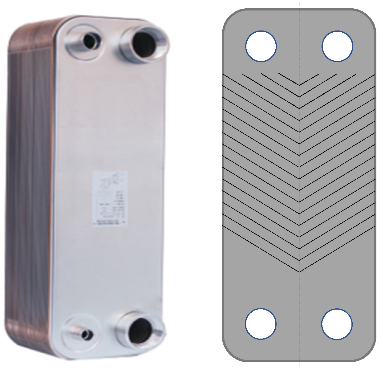
2.1.1. Plate Heat Exchanger
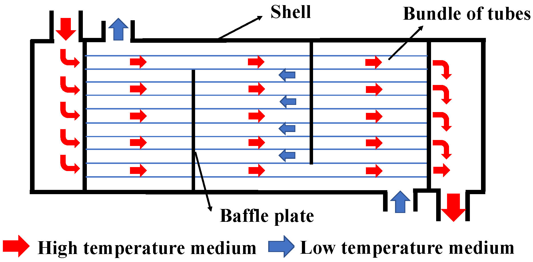
2.1.2. Shell–and–Tube Heat Exchanger
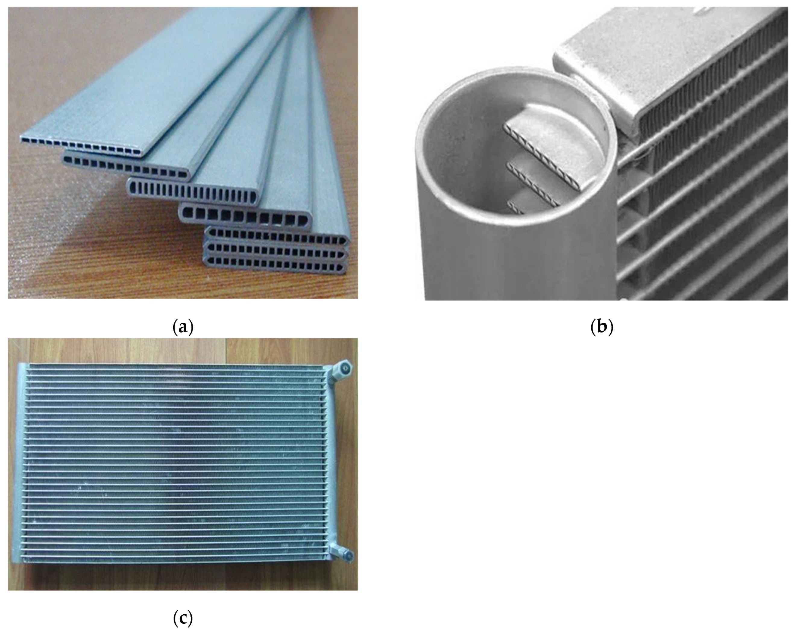
2.1.3. Fin–and–Tube Heat Exchanger
2.2. Comparison and/or Screening of Heat Exchangers in the ORC
2.2.1. Comparison of ORC Using Different Types of Heat Exchangers
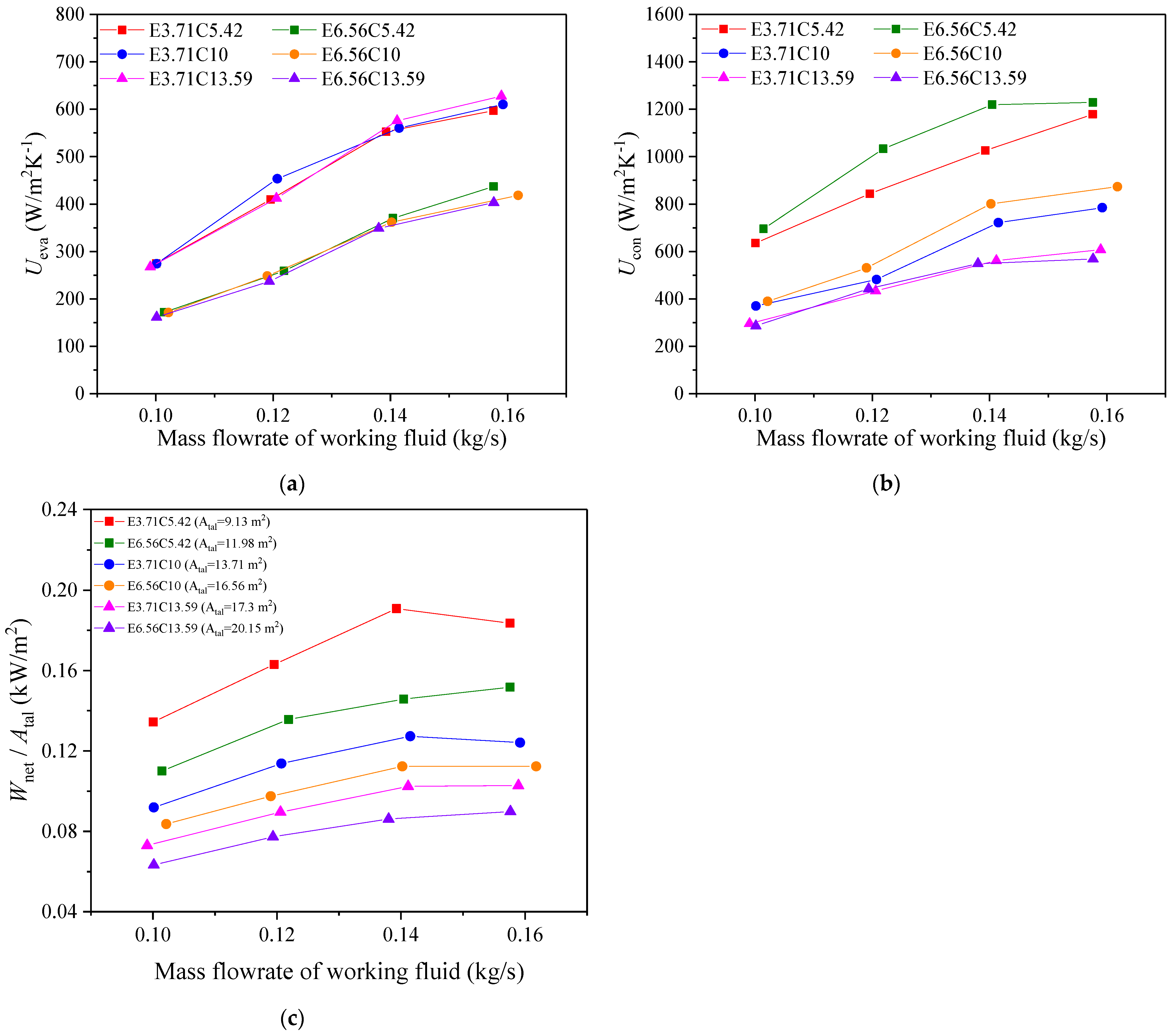
2.2.2. Comparison of ORC Using Heat Exchangers with Different Structural Parameters
3. Heat Transfer Enhancement and/or Novel Heat Exchanger Applied in ORC
3.1. Innovative Material Used in the Heat Exchanger
3.2. Novel Structure or Arrangement of Heat Exchangers
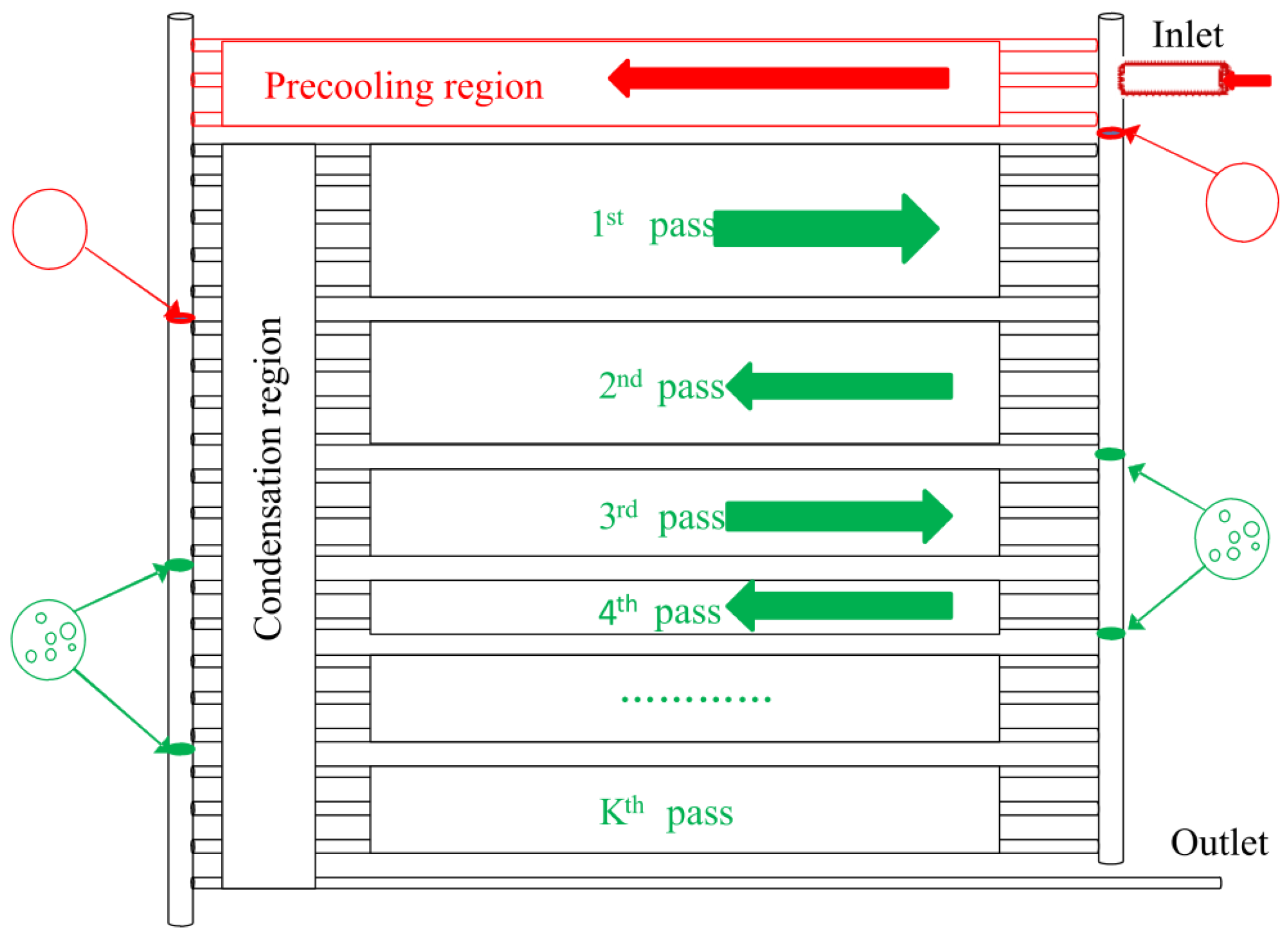
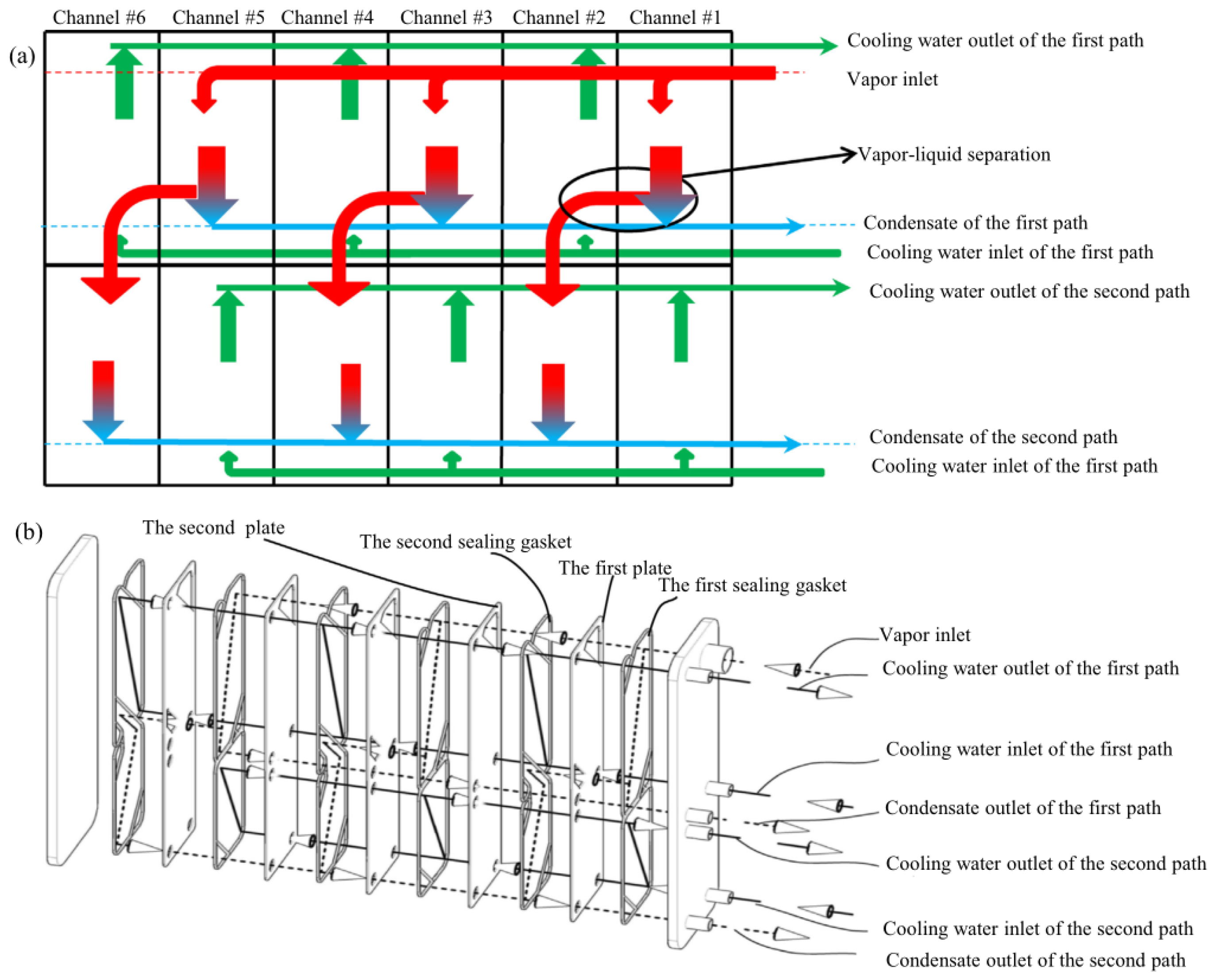
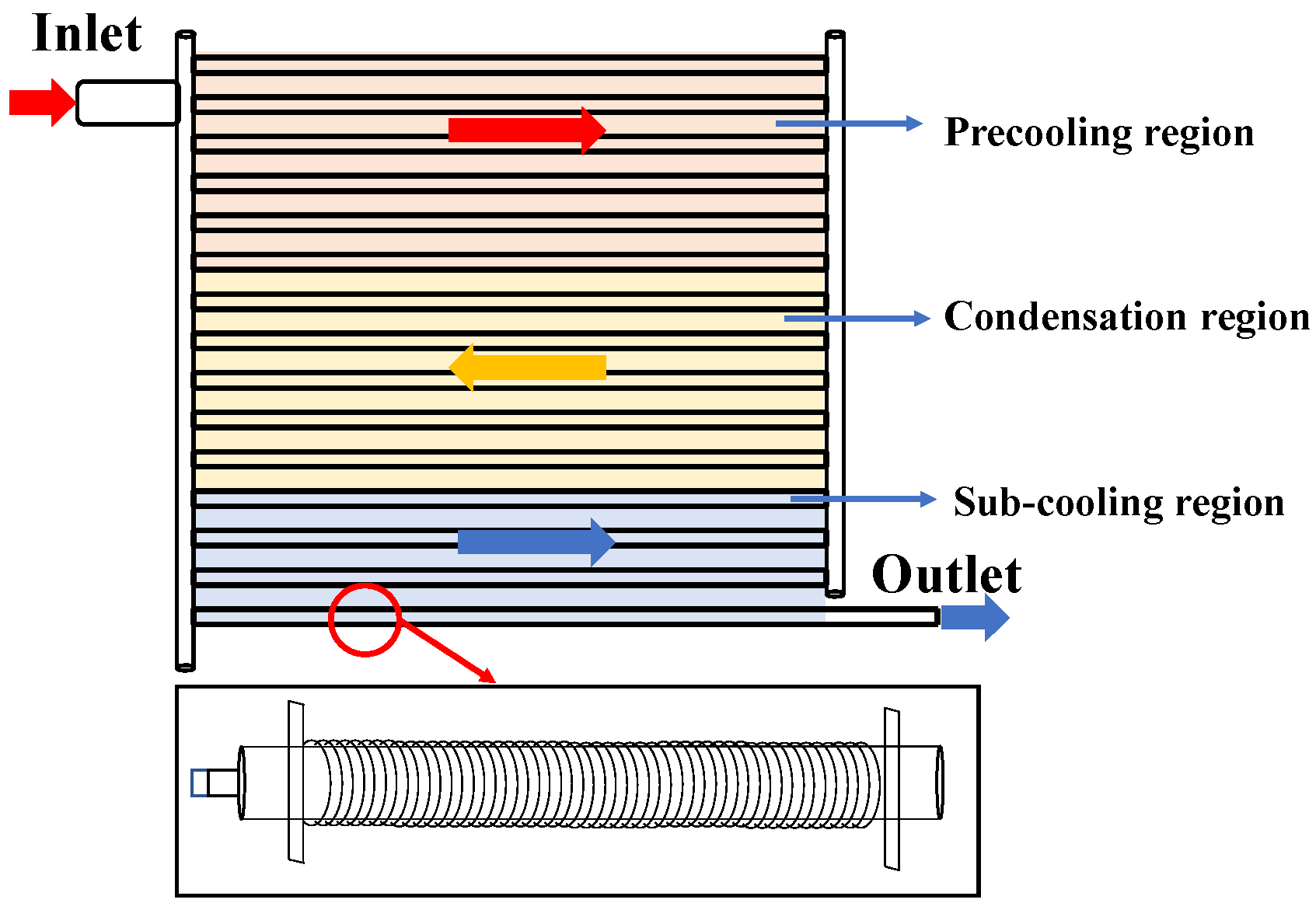
3.3. Liquid–Vapor Separation Concept Applied in the Heat Exchanger
4. ORC Performance Enhancement via Heat Transfer Enhancement Technology or Novel Heat Exchanger
4.1. ORC with Novel Heat Exchangers
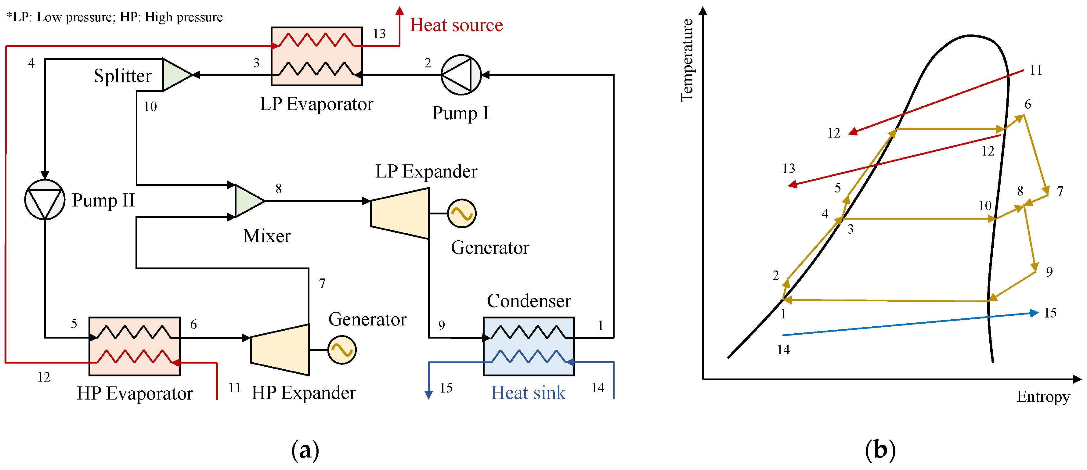
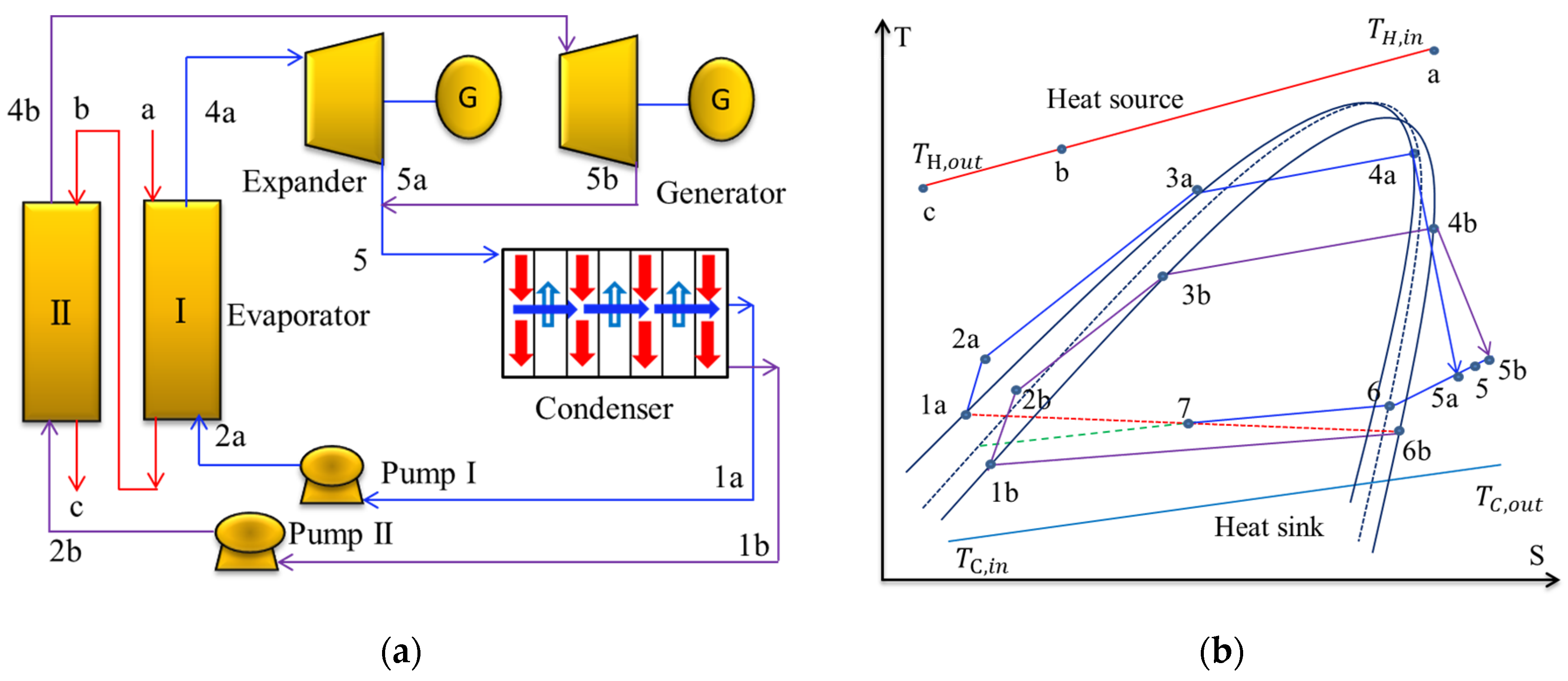
4.2. Dual/Multi–Pressure Evaporating ORC
4.2.1. Dual/Multi–Pressure Evaporating ORC with Liquid–Vapor Separation Condensation Method
4.2.2. Dual/Multi–Pressure Evaporating ORC with Partial Evaporation
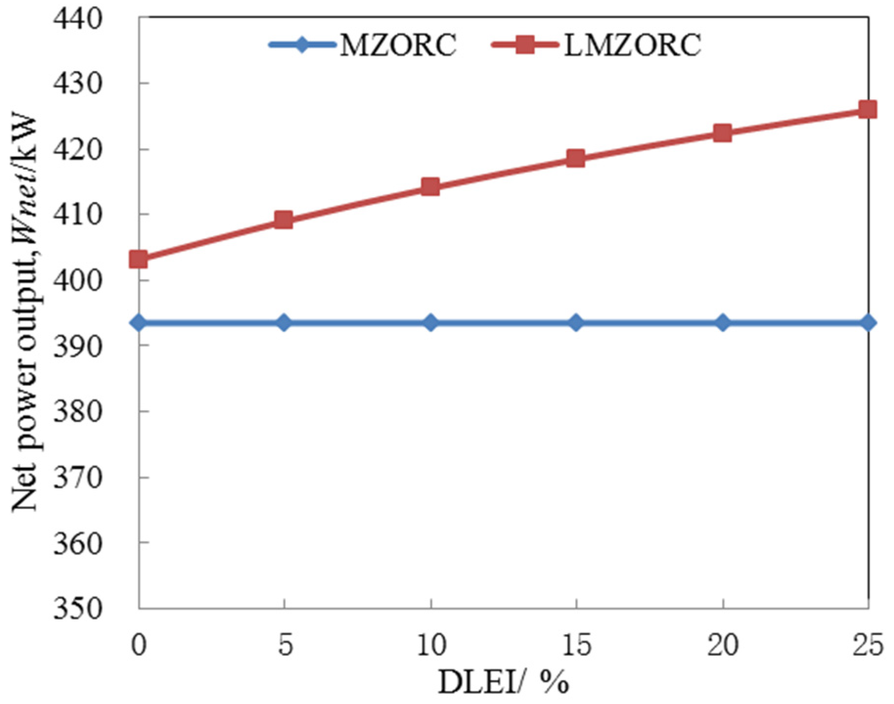
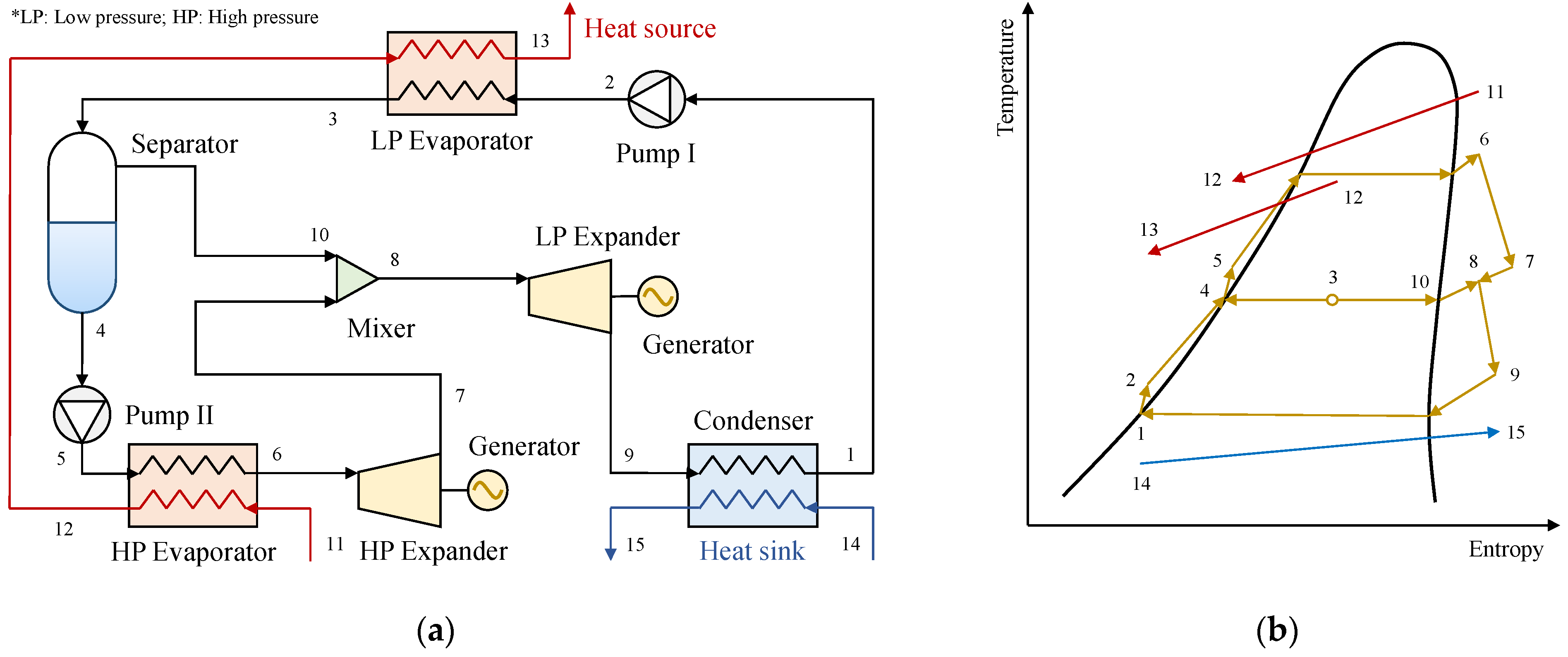
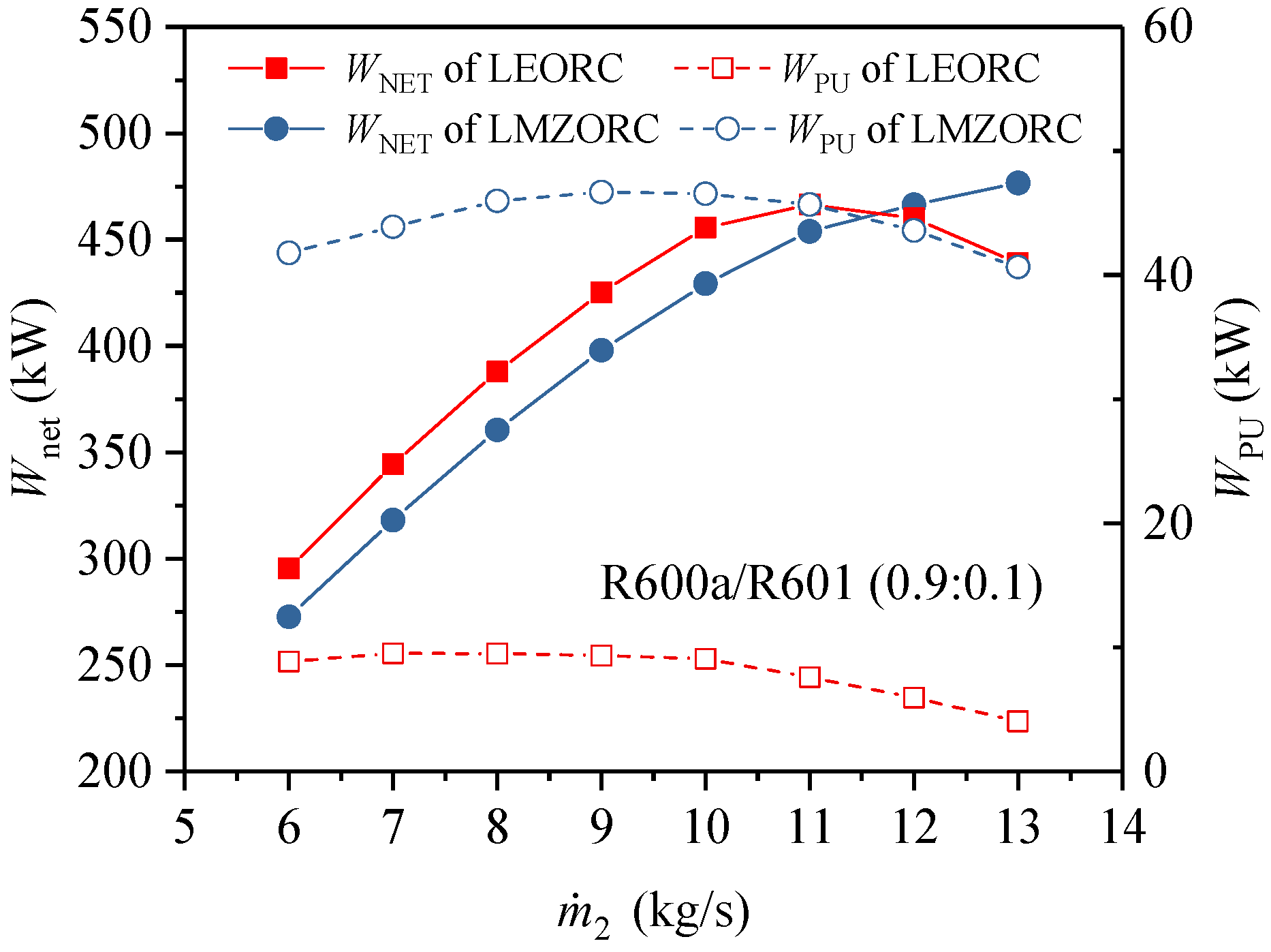
4.2.3. Dual/Multi–Pressure Evaporating ORC Integrates Liquid–Vapor Separation Condensation and Partial Evaporation
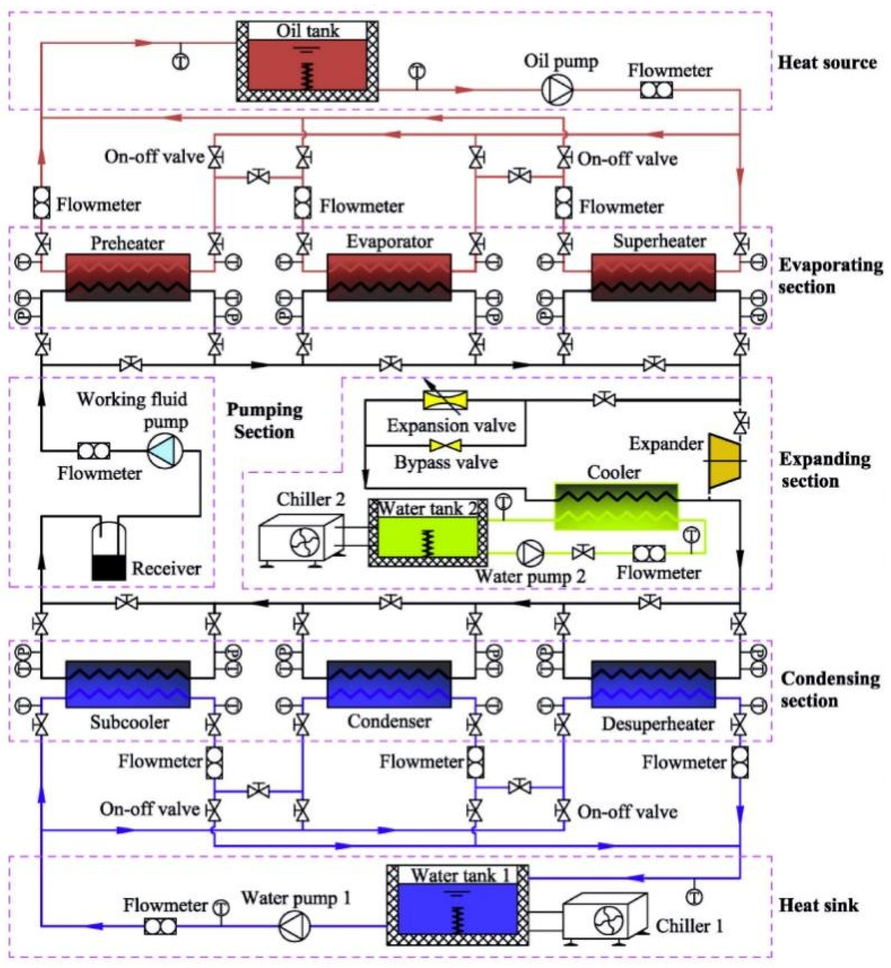
5. Design and Optimization of Heat Exchanger and ORC System
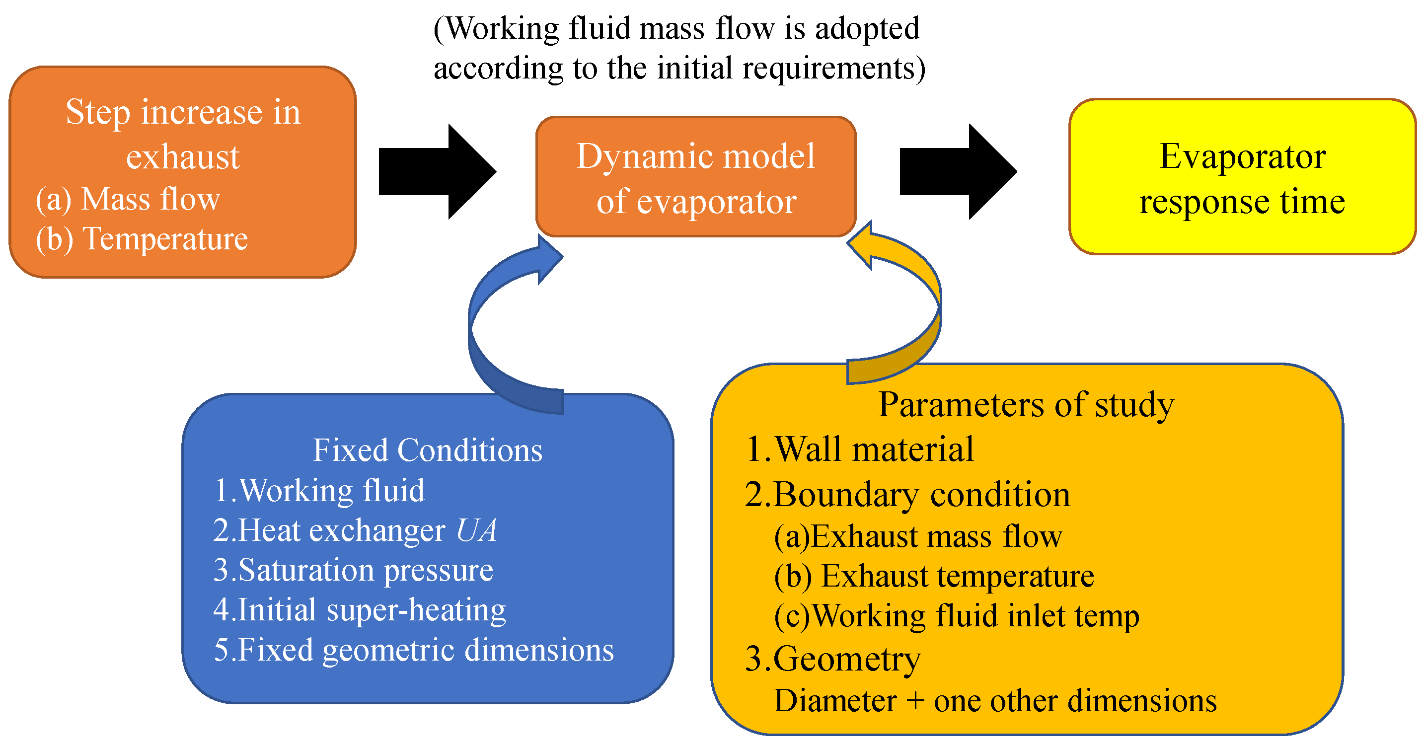
5.1. Design Modelling of Heat Exchanger
5.2. Heat Transfer Correlation

| Ref. | Types | Methods | Challenges | Applications |
|---|---|---|---|---|
| [86] | Plate heat exchangers | Finite element method based on equal enthalpy difference | Component selection aiming at minimizing cost | Under supercritical conditions |
| [44] | Plate condenser | – | Evaluating the effect of plate spacing on operating performance | Common approach |
| [97] | Plate heat exchangers | 1D pressure–enthalpy based discretized method | Determining the dimension of the heat exchangers | Common approach |
| [90] | Fin–and–tube evaporator | Finite element method based on equal enthalpy difference | Evaluating the off–design operating performance | Engine exhaust heat recovery |
| [85,98] | Fin–and–tube evaporator | Finite element method modeled in the commercial software Dymola using the commercial TIL library | Dynamic time response | Engine exhaust heat recovery |
| [99] | Fin–and–tube evaporator | CFD simulation model modeled in the commercial software Fluent | Evaluating qualitatively the thermal–hydraulic characteristics | Engine exhaust heat recovery |
| [100] | Fin–and–tube evaporator | Finite–volume dynamic model | Dynamic time response | Heavy–duty vehicle waste heat recovery |
| [40,41] | Fin–and–tube or shell–and–tube evaporator | 1D Finite–volume dynamic model modeled in the commercial software Dymola using the commercial TIL library | Dynamic time response | Engine exhaust heat recovery |
| [101] | Shell–and–tube heat exchanger with double–segmental baffles | Finite–volume dynamic model modeled in the commercial software DYMOLA 2015 FD01 | Experimental validation | Single phase flow |
| [88] | Shell–and–tube heat exchangers | Logarithmic mean temperature difference method and a two–stage Taguchi method | Evaluating the influence of the solar irradiation intensity on the optimum design parameters | Solar ORC |
| [102] | Shell–and–tube pool boilers | Finite–volume dynamic model | Dynamic time response | Common approach |
| [87] | Shell–and–tube condenser with micro–channel | Semi–empirical model | Experimental validation | Micro ORC |
5.3. Simultaneous Optimization of Heat Exchanger and ORC System
| Ref. | Type | Algorithm | Objectives | Variables |
|---|---|---|---|---|
| [104] | Plate condenser | NSGA–II | The total heat transfer surface area and pressure drop | Length, width and plate spacing |
| [105] | Plate evaporator | NSGA–II | Minimum cost of evaporator and minimum pressure drop | Length, width and plate spacing |
| [56] | Shell–and–tube evaporator with | Particle swarm | Volume fraction of the vapor at the tube outlet | Angular frequency and oscillating velocity amplitude |
| [59] | Shell and louvered fin mini–tubes heat exchanger | – | Maximize the system efficiency | Heat transfer load, mass flow rate, evaporation and condensation pressure |
| [33] | Shell–and–tube heat exchangers | – | Minimize specific investment cost | Pinch point temperature differences in the evaporator and condenser, evaporation pressure, turbine inlet temperature |
| [106] | Shell–and–tube heat exchangers | Gradient–based optimization method | Maximize the system efficiency | Tube outside diameter, relative tube pitch, relative baffle cut, baffle spacing, shell diameter, ratio of tube diameter to shell diameter |
| [36] | Plate heat exchangers and shell–and–tube heat exchangers | Gradient–based optimization method | Maximize the system efficiency | Corrugation amplitude, width, angle, channels, ratio of corrugation width to corrugation amplitude; shell diameter, tube outside diameter, relative tube pitch, relative baffle cut, baffle spacing, ratio of tube diameter to shell diameter |
| [115] | Fin–and–tube evaporator | NSGA–II | Net power output per unit heat transfer area and exergy destruction rate | Evaporation pressure, superheat degree and condensation temperature |
| [108] | Fin–and–tube evaporator | Particle swarm | Volume of tube bundle, exhaust pressure drop, and total annual cost | Inlet radius, fin height, fin thickness and fin spacing. Operating pressure and temperature of the ORC system |
| [55] | Fin–and–tube evaporator | Genetic algorithms | Influence of the evaporator on the operation of the diesel engine | Ellipticity ratio of the tube in the evaporator and tooth depth of the star–shaped fin |
| [39] | Shell–and–tube heat exchangers and plate heat exchangers | Genetic algorithms | Maximum exergy efficiency, minimum specific cost and minimum heat exchanger area per unit power output | The outer diameters of the tubes, the tube length, the outside diameter of the shell, pitch between the tube centers, and the baffle spacing; The plate length, plate width, plate thickness, chevron angle, and channel spacing |
| [107] | Fin–and–tube condenser with liquid–separated condensation | CONOPT, MINOS, and SNOPT | Minimize the total annual cost | Continuous variables (e.g., tube length, tube diameter, fin length, fin thickness), discrete variables (e.g., tube number per pass, tube pass number, fin number per length, total tube number) |
| [73] | Fin–and–tube condenser with liquid–separated condensation | CONOPT, MINOS, and SNOPT | Minimize the total annual cost | Tube diameter and tube length, the selection of integer variables (e.g., total tube number, number of passes of LSC, tube number per pass, and fin number per unit tube length), and correlation coefficients |
6. Prospects
7. Conclusions
Author Contributions
Funding
Data Availability Statement
Conflicts of Interest
References
- Cui, Y.; Zhao, H. Marine renewable energy project: The environmental implication and sustainable technology. Ocean Coast. Manag. 2023, 232, 106415. [Google Scholar] [CrossRef]
- Anika, O.C.; Nnabuife, S.G.; Bello, A.; Okoroafor, E.R.; Kuang, B.; Villa, R. Prospects of low and zero–carbon renewable fuels in 1.5–degree net zero emission actualisation by 2050: A critical review. Carbon Capture Sci. Technol. 2022, 5, 100072. [Google Scholar] [CrossRef]
- Farhat, O.; Faraj, J.; Hachem, F.; Castelain, C.; Khaled, M. A recent review on waste heat recovery methodologies and applications: Comprehensive review, critical analysis and potential recommendations. Clean. Eng. Technol. 2022, 6, 100387. [Google Scholar] [CrossRef]
- Peris, B.; Navarro–Esbrí, J.; Molés, F.; Mota–Babiloni, A. Experimental study of an ORC (organic Rankine cycle) for low grade waste heat recovery in a ceramic industry. Energy 2015, 85, 534–542. [Google Scholar] [CrossRef]
- Patil, V.R.; Biradar, V.I.; Shreyas, R.; Garg, P.; Orosz, M.S.; Thirumalai, N. Techno–economic comparison of solar organic Rankine cycle (ORC) and photovoltaic (PV) systems with energy storage. Renew. Energy 2017, 113, 1250–1260. [Google Scholar] [CrossRef]
- Wang, M.; Jing, R.; Zhang, H.; Meng, C.; Li, N.; Zhao, Y. An innovative Organic Rankine Cycle (ORC) based Ocean Thermal Energy Conversion (OTEC) system with performance simulation and multi–objective optimization. Appl. Therm. Eng. 2018, 145, 743–754. [Google Scholar] [CrossRef]
- DiPippo, R. Geothermal power plants: Evolution and performance assessments. Geothermics 2015, 53, 291–307. [Google Scholar] [CrossRef]
- Qiu, G.; Shao, Y.; Li, J.; Liu, H.; Riffat, S. Experimental investigation of a biomass–fired ORC–based micro–CHP for domestic applications. Fuel 2012, 96, 374–382. [Google Scholar] [CrossRef] [Green Version]
- Quoilin, S.; Broek, M.V.D.; Declaye, S.; Dewallef, P.; Lemort, V. Techno–economic survey of Organic Rankine Cycle (ORC) systems. Renew. Sustain. Energy Rev. 2013, 22, 168–186. [Google Scholar] [CrossRef] [Green Version]
- History of ORC. Knowledge Center for Organic Rankine Cycle. Available online: http://www.kcorc.org/en/science–technology/history/ (accessed on 7 November 2022).
- Tartière, T.; Astolfi, M. A World Overview of the Organic Rankine Cycle Market. Energy Procedia 2017, 129, 2–9. [Google Scholar] [CrossRef]
- Tocci, L.; Pal, T.; Pesmazoglou, I.; Franchetti, B. Small Scale Organic Rankine Cycle (ORC): A Techno–Economic Review. Energies 2017, 10, 413. [Google Scholar] [CrossRef]
- Lecompte, S.; Huisseune, H.; Van Den Broek, M.; Vanslambrouck, B.; De Paepe, M. Review of organic Rankine cycle (ORC) architectures for waste heat recovery. Renew. Sustain. Energy Rev. 2015, 47, 448–461. [Google Scholar] [CrossRef]
- Kumar, A.; Rakshit, D. A critical review on waste heat recovery utilization with special focus on Organic Rankine Cycle applications. Clean. Eng. Technol. 2021, 5, 100292. [Google Scholar] [CrossRef]
- Chen, Q.; Xu, J.; Chen, H. A new design method for Organic Rankine Cycles with constraint of inlet and outlet heat carrier fluid temperatures coupling with the heat source. Appl. Energy 2012, 98, 562–573. [Google Scholar] [CrossRef]
- Chen, J.; Zheng, X.; Guo, G.; Luo, X.; Chen, Y.; Yang, Z. A flexible and multi–functional organic Rankine cycle system: Preliminary experimental study and advanced exergy analysis. Energy Convers. Manag. 2019, 187, 339–355. [Google Scholar] [CrossRef]
- Walraven, D.; Laenen, B.; D’Haeseleer, W. Economic system optimization of air–cooled organic Rankine cycles powered by low–temperature geothermal heat sources. Energy 2015, 80, 104–113. [Google Scholar] [CrossRef] [Green Version]
- Fawaz, A.; Hua, Y.; Le Corre, S.; Fan, Y.; Luo, L. Topology optimization of heat exchangers: A review. Energy 2022, 252, 124053. [Google Scholar] [CrossRef]
- Ajarostaghi, S.S.M.; Zaboli, M.; Javadi, H.; Badenes, B.; Urchueguia, J.F. A Review of Recent Passive Heat Transfer Enhancement Methods. Energies 2022, 15, 986. [Google Scholar] [CrossRef]
- Shanker, G.R.; Homan, K. Convective transport from geothermal borehole heat exchangers embedded in a fluid–saturated porous medium. Renew. Energy 2022, 196, 328–342. [Google Scholar] [CrossRef]
- Spizzichino, M.; Sinibaldi, G.; Romano, G. Experimental investigation on fluid mechanics of micro–channel heat transfer devices. Exp. Therm. Fluid Sci. 2020, 118, 110141. [Google Scholar] [CrossRef]
- Kaur, I.; Singh, P. State–of–the–art in heat exchanger additive manufacturing. Int. J. Heat Mass Transf. 2021, 178, 121600. [Google Scholar] [CrossRef]
- Hussein, H.A.M.; Zulkifli, R.; Mahmood, W.M.F.B.W.; Ajeel, R.K. Structure parameters and designs and their impact on performance of different heat exchangers: A review. Renew. Sustain. Energy Rev. 2022, 154, 111842. [Google Scholar] [CrossRef]
- Zhar, R.; Allouhi, A.; Jamil, A.; Lahrech, K. A comparative study and sensitivity analysis of different ORC configurations for waste heat recovery. Case Stud. Therm. Eng. 2021, 28, 101608. [Google Scholar] [CrossRef]
- Lu, P.; Luo, X.; Wang, J.; Chen, J.; Liang, Y.; Yang, Z.; He, J.; Wang, C.; Chen, Y. Thermodynamic analysis and evaluation of a novel composition adjustable Carnot battery under variable operating scenarios. Energy Convers. Manag. 2022, 269, 116117. [Google Scholar] [CrossRef]
- Zhao, Y.; Liu, G.; Li, L.; Yang, Q.; Tang, B.; Liu, Y. Expansion devices for organic Rankine cycle (ORC) using in low temperature heat recovery: A review. Energy Convers. Manag. 2019, 199, 111944. [Google Scholar] [CrossRef]
- Alshammari, F.; Karvountzis–Kontakiotis, A.; Pesyridis, A.; Usman, M. Expander Technologies for Automotive Engine Organic Rankine Cycle Applications. Energies 2018, 11, 1905. [Google Scholar] [CrossRef] [Green Version]
- Zhang, C.; Liu, C.; Wang, S.; Xu, X.; Li, Q. Thermo–economic comparison of subcritical organic Rankine cycle based on different heat exchanger configurations. Energy 2017, 123, 728–741. [Google Scholar] [CrossRef]
- Arsenyeva, O.P.; Tovazhnyansky, L.L.; Kapustenko, P.O.; Khavin, G.L. Optimal design of plate–and–frame heat exchangers for efficient heat recovery in process industries. Energy 2011, 36, 4588–4598. [Google Scholar] [CrossRef] [Green Version]
- Luo, J.; Lu, P.; Chen, K.; Luo, X.; Chen, J.; Liang, Y.; Yang, Z.; Chen, Y. Experimental and simulation investigation on the heat exchangers in an ORC under various heat source/sink conditions. Energy 2023, 264, 126189. [Google Scholar] [CrossRef]
- Chen, L.-Y.; Adi, V.S.K.; Laxmidewi, R. Shell and tube heat exchanger flexible design strategy for process operability. Case Stud. Therm. Eng. 2022, 37, 102163. [Google Scholar] [CrossRef]
- Caputo, A.C.; Federici, A.; Pelagagge, P.M.; Salini, P. On the design of shell–and–tube heat exchangers under uncertain operating conditions. Appl. Therm. Eng. 2022, 212, 118541. [Google Scholar] [CrossRef]
- Li, J.; Yang, Z.; Hu, S.; Yang, F.; Duan, Y. Effects of shell–and–tube heat exchanger arranged forms on the thermo–economic performance of organic Rankine cycle systems using hydrocarbons. Energy Convers. Manag. 2019, 203, 112248. [Google Scholar] [CrossRef]
- Banu, P.A.; Dhanapal, B.; Pillai, T.M.; Chellappa, B.; Sathyamurthy, R. Thermodynamic and hydraulic design characteristics of the fin tube heat exchanger. Mater. Today Proc. 2022, 62, 2380–2387. [Google Scholar] [CrossRef]
- Tahseen, T.A.; Ishak, M.; Rahman, M. An overview on thermal and fluid flow characteristics in a plain plate finned and un–finned tube banks heat exchanger. Renew. Sustain. Energy Rev. 2015, 43, 363–380. [Google Scholar] [CrossRef] [Green Version]
- Walraven, D.; Laenen, B.; D’Haeseleer, W. Comparison of shell–and–tube with plate heat exchangers for the use in low–temperature organic Rankine cycles. Energy Convers. Manag. 2014, 87, 227–237. [Google Scholar] [CrossRef] [Green Version]
- Lee, Y.-R.; Kuo, C.-R.; Liu, C.-H.; Fu, B.-R.; Wang, C.-C. Response of a 50kW Organic Rankine Cycle System Subject to Influence of Evaporators. Energy Procedia 2014, 61, 635–638. [Google Scholar] [CrossRef] [Green Version]
- Bull, J.; Buick, J.M.; Radulovic, J. Heat Exchanger Sizing for Organic Rankine Cycle. Energies 2020, 13, 3615. [Google Scholar] [CrossRef]
- Xu, J.; Luo, X.; Chen, Y.; Mo, S. Multi–criteria Design Optimization and Screening of Heat Exchangers for a Subcritical ORC. Energy Procedia 2015, 75, 1639–1645. [Google Scholar] [CrossRef] [Green Version]
- Jiménez–Arreola, M.; Wieland, C.; Romagnoli, A. Dynamic response comparison of direct and indirect evaporation options in ORC systems for waste heat recovery. Energy Procedia 2019, 158, 1606–1612. [Google Scholar] [CrossRef]
- Jiménez–Arreola, M.; Wieland, C.; Romagnoli, A. Direct vs indirect evaporation in Organic Rankine Cycle (ORC) systems: A comparison of the dynamic behavior for waste heat recovery of engine exhaust. Appl. Energy 2019, 242, 439–452. [Google Scholar] [CrossRef]
- Chatzopoulou, M.A.; Lecompte, S.; De Paepe, M.; Markides, C.N. Off–design optimisation of organic Rankine cycle (ORC) engines with different heat exchangers and volumetric expanders in waste heat recovery applications. Appl. Energy 2019, 253, 113442. [Google Scholar] [CrossRef]
- Chatzopoulou, M.A.; Lecompte, S.; De Paepe, M.; Markides, C.N. Off–design operation of ORC engines with different heat exchanger architectures in waste heat recovery applications. Energy Procedia 2019, 158, 2348–2353. [Google Scholar] [CrossRef]
- Rohmah, N.; Pikra, G.; Purwanto, A.J.; Pramana, R.I. The Effect of Plate Spacing in Plate Heat Exchanger Design as a Condenser in Organic Rankine cycle for Low Temperature Heat Source. Energy Procedia 2015, 68, 87–96. [Google Scholar] [CrossRef] [Green Version]
- Ravi, R.; Pachamuthu, S. Design and Development of Innovative Protracted–Finned Counter Flow Heat Exchanger (PFCHE) for an Engine WHR and Its Impact on Exhaust Emissions. Energies 2018, 11, 2717. [Google Scholar] [CrossRef] [Green Version]
- Luo, X.; Yi, Z.; Chen, Z.; Chen, Y.; Mo, S. Performance comparison of the liquid–vapor separation, parallel flow, and serpentine condensers in the organic Rankine cycle. Appl. Therm. Eng. 2016, 94, 435–448. [Google Scholar] [CrossRef]
- Zhang, Y.-F.; Li, M.-J.; Ren, X.; Duan, X.-Y.; Wu, C.-J.; Xi, H.; Feng, Y.-Q.; Gong, L.; Hung, T.-C. Effect of heat source supplies on system behaviors of ORCs with different capacities: An experimental comparison between the 3 kW and 10 kW unit. Energy 2022, 254, 124267. [Google Scholar] [CrossRef]
- Zheng, X.; Luo, X.; Luo, J.; Chen, J.; Liang, Y.; Yang, Z.; Chen, Y.; Wang, H. Experimental investigation of operation behavior of plate heat exchangers and their influences on organic Rankine cycle performance. Energy Convers. Manag. 2020, 207, 112528. [Google Scholar] [CrossRef]
- Venegas, T.; Qu, M.; Nawaz, K.; Wang, L. Critical review and future prospects for desiccant coated heat exchangers: Materials, design, and manufacturing. Renew. Sustain. Energy Rev. 2021, 151, 111531. [Google Scholar] [CrossRef]
- Khail, A.A.; Erişen, A. Heat transfer and performance enhancement investigation of novel plate heat exchanger. Therm. Sci. Eng. Prog. 2022, 34, 101368. [Google Scholar] [CrossRef]
- Aláez, S.G.; Bombarda, P.; Invernizzi, C.; Iora, P.; Silva, P. Evaluation of ORC modules performance adopting commercial plastic heat exchangers. Appl. Energy 2015, 154, 882–890. [Google Scholar] [CrossRef]
- Kim, D.Y.; Kim, K.C. Thermal performance of brazed metalfoam–plate heat exchanger as an evaporator for organic Rankine cycle. Energy Procedia 2017, 129, 451–458. [Google Scholar] [CrossRef]
- Nematollahi, O.; Abadi, G.B.; Kim, D.Y.; Kim, K.C. Experimental study of the effect of brazed compact metal–foam evaporator in an organic Rankine cycle performance: Toward a compact ORC. Energy Convers. Manag. 2018, 173, 37–45. [Google Scholar] [CrossRef]
- Cao, S.; Xu, J.; Li, Y.; Yan, Y. Condensation heat transfer of R245fa in a shell–tube heat exchanger at slightly inclined angles. Int. J. Therm. Sci. 2017, 115, 197–209. [Google Scholar] [CrossRef]
- Zhang, W.; Yang, F.; Zhang, H.; Ping, X.; Yan, D. Numerical analysis and optimization design of fin–and–tube evaporator in organic Rankine cycle system for diesel engine waste heat recovery. Int. J. Heat Mass Transf. 2021, 175, 121376. [Google Scholar] [CrossRef]
- Zhang, W.; Yang, F.; Zhang, H.; Ping, X.; Yan, D.; Wang, C. Application of two–phase pulsating flow in organic Rankine cycle system for diesel engine waste heat recovery. Energy 2021, 243, 122776. [Google Scholar] [CrossRef]
- Wang, D.; Lu, H.; Li, L.; Fu, S.; Dai, X.; Shi, L. Comprehensive comparison of the applicability of internally ribbed and microfin tubes for TORC systems. Int. J. Heat Mass Transf. 2022, 186, 122470. [Google Scholar] [CrossRef]
- Nguyen, D.H.; Ahn, H.S. A comprehensive review on micro/nanoscale surface modification techniques for heat transfer enhancement in heat exchanger. Int. J. Heat Mass Transf. 2021, 178, 121601. [Google Scholar] [CrossRef]
- Mastrullo, R.; Mauro, A.W.; Revellin, R.; Viscito, L. Modeling and optimization of a shell and louvered fin mini–tubes heat exchanger in an ORC powered by an internal combustion engine. Energy Convers. Manag. 2015, 101, 697–712. [Google Scholar] [CrossRef]
- Chen, J.; Zhu, K.; Luo, X.; Chen, Y.; Yang, Z. Application of liquid–separation condensation to plate heat exchanger: Comparative studies. Appl. Therm. Eng. 2019, 157, 113739. [Google Scholar] [CrossRef]
- Li, Y.; Luo, X.; Wang, Z.; Yang, Z.; Chen, J.; Liang, Y.; Wang, C.; Chen, Y. Numerical simulation on the header–orifice structure–based liquid–vapor separator used in liquid–separation condenser. Chem. Eng. Sci. 2021, 235, 116475. [Google Scholar] [CrossRef]
- Chen, J.; Li, Y.; Ding, R.; Lin, X.; Chen, Y.; Luo, X.; Yang, Z. Comparative performance of air–conditioning systems with different refrigerant circuitries in liquid–separation condenser. Int. J. Refrig. 2018, 92, 154–164. [Google Scholar] [CrossRef]
- Chen, J.; Ding, R.; Li, Y.; Lin, X.; Chen, Y.; Luo, X.; Yang, Z. Application of a vapor–liquid separation heat exchanger to the air conditioning system at cooling and heating modes. Int. J. Refrig. 2018, 100, 27–36. [Google Scholar] [CrossRef]
- Huang, K.; Li, J.; Chen, J.; Chen, Y.; Luo, X.; Liang, Y.; He, J.; Yang, Z. Explorations of multi-pass-orifice header in the liquid-separation condenser by using CFD simulation. Int. J. Heat Mass Tran. 2023, 200, 123482. [Google Scholar] [CrossRef]
- Li, J.; Liu, Q.; Duan, Y.; Yang, Z. Performance analysis of organic Rankine cycles using R600/R601a mixtures with liquid–separated condensation. Appl. Energy 2017, 190, 376–389. [Google Scholar] [CrossRef]
- Li, J.; Hu, S.; Yang, F.; Duan, Y.; Yang, Z. Thermo–economic performance evaluation of emerging liquid–separated condensation method in single–pressure and dual–pressure evaporation organic Rankine cycle systems. Appl. Energy 2019, 256, 113974. [Google Scholar] [CrossRef]
- Li, J.; Yang, Z.; Hu, S.; Yang, F.; Duan, Y. Thermo–economic performance improvement of butane/isopentane mixtures in organic Rankine cycles by liquid–separated condensation method. Appl. Therm. Eng. 2020, 181, 115941. [Google Scholar] [CrossRef]
- Luo, X.; Liang, Z.; Guo, G.; Wang, C.; Chen, Y.; Ponce–Ortega, J.M.; El–Halwagi, M.M. Thermo–economic analysis and optimization of a zoetropic fluid organic Rankine cycle with liquid–vapor separation during condensation. Energy Convers. Manag. 2017, 148, 517–532. [Google Scholar] [CrossRef]
- Lu, P.; Luo, X.; Wang, J.; Chen, J.; Liang, Y.; Yang, Z.; Wang, C.; Chen, Y. Thermo–economic design, optimization, and evaluation of a novel zeotropic ORC with mixture composition adjustment during operation. Energy Convers. Manag. 2021, 230, 113771. [Google Scholar] [CrossRef]
- Yi, Z.; Luo, X.; Yang, Z.; Wang, C.; Chen, J.; Chen, Y.; Ponce–Ortega, J.M. Thermo–economic–environmental optimization of a liquid separation condensation–based organic Rankine cycle driven by waste heat. J. Clean. Prod. 2018, 184, 198–210. [Google Scholar] [CrossRef]
- Xu, B.; Rathod, D.; Yebi, A.; Filipi, Z.; Onori, S.; Hoffman, M. A comprehensive review of organic rankine cycle waste heat recovery systems in heavy–duty diesel engine applications. Renew. Sustain. Energy Rev. 2019, 107, 145–170. [Google Scholar] [CrossRef]
- Qureshi, I.A.; Waqas, A.; Ali, M.; Mehmood, A.; Javed, A. Performance evaluation of ORC system using evacuated flat plate Photovoltaic–Thermal collector as an evaporator. Sol. Energy 2021, 230, 859–873. [Google Scholar] [CrossRef]
- Luo, X.; Yi, Z.; Zhang, B.; Mo, S.; Wang, C.; Song, M.; Chen, Y. Mathematical modelling and optimization of the liquid separation condenser used in organic Rankine cycle. Appl. Energy 2017, 185, 1309–1323. [Google Scholar] [CrossRef]
- Yi, Z.; Luo, X.; Chen, J.; Chen, Y. Mathematical modelling and optimization of a liquid separation condenser–based organic Rankine cycle used in waste heat utilization. Energy 2017, 139, 916–934. [Google Scholar] [CrossRef]
- Luo, X.; Huang, R.; Yang, Z.; Chen, J.; Chen, Y. Performance investigation of a novel zeotropic organic Rankine cycle coupling liquid separation condensation and multi–pressure evaporation. Energy Convers. Manag. 2018, 161, 112–127. [Google Scholar] [CrossRef]
- Hu, S.; Li, J.; Yang, F.; Yang, Z.; Duan, Y. Thermodynamic analysis of serial dual–pressure organic Rankine cycle under off–design conditions. Energy Convers. Manag. 2020, 213, 112837. [Google Scholar] [CrossRef]
- Liang, Z.; Liang, Y.; Luo, X.; Chen, J.; Yang, Z.; Wang, C.; Chen, Y. Synthesis and simultaneous optimization of multi–heat source multi–pressure evaporation organic Rankine cycle with mixed working fluid. Energy Convers. Manag. 2021, 251, 114930. [Google Scholar] [CrossRef]
- Zhang, J.; Zhang, X.; Zhang, Z.; Zhou, P.; Zhang, Y.; Yuan, H. Performance improvement of ocean thermal energy conversion organic Rankine cycle under temperature glide effect. Energy 2022, 246, 123440. [Google Scholar] [CrossRef]
- Li, D.; He, Z.; Wang, Q.; Wang, X.; Wu, W.; Xing, Z. Thermodynamic analysis and optimization of a partial evaporating dual–pressure organic rankine cycle system for low–grade heat recovery. Appl. Therm. Eng. 2020, 185, 116363. [Google Scholar] [CrossRef]
- Surendran, A.; Seshadri, S. Design and performance analysis of a novel Transcritical Regenerative Series Two stage Organic Rankine Cycle for dual source waste heat recovery. Energy 2020, 203, 117800. [Google Scholar] [CrossRef]
- Yu, W.; Xu, Y.; Wang, H.; Ge, Z.; Wang, J.; Zhu, D.; Xia, Y. Thermodynamic and thermoeconomic performance analyses and optimization of a novel power and cooling cogeneration system fueled by low–grade waste heat. Appl. Therm. Eng. 2020, 179, 115667. [Google Scholar] [CrossRef]
- Surendran, A.; Seshadri, S. An ejector based Transcritical Regenerative Series Two–Stage Organic Rankine Cycle for dual/multi–source heat recovery applications. Therm. Sci. Eng. Prog. 2021, 27, 101158. [Google Scholar] [CrossRef]
- Meng, N.; Li, T.; Gao, X.; Liu, Q.; Li, X.; Gao, H. Thermodynamic and techno–economic performance comparison of two–stage series organic Rankine cycle and organic Rankine flash cycle for geothermal power generation from hot dry rock. Appl. Therm. Eng. 2021, 200, 117715. [Google Scholar] [CrossRef]
- Huang, Y.; Chen, J.; Chen, Y.; Luo, X.; Liang, Y.; He, J.; Yang, Z. Performance explorations of an organic Rankine cycle featured with separating and mixing composition of zeotropic mixture. Energy 2022, 257, 124535. [Google Scholar] [CrossRef]
- Jiménez–Arreola, M.; Pili, R.; Wieland, C.; Romagnoli, A. Analysis and comparison of dynamic behavior of heat exchangers for direct evaporation in ORC waste heat recovery applications from fluctuating sources. Appl. Energy 2018, 216, 724–740. [Google Scholar] [CrossRef]
- Karellas, S.; Schuster, A.; Leontaritis, A.-D. Influence of supercritical ORC parameters on plate heat exchanger design. Appl. Therm. Eng. 2012, 33–34, 70–76. [Google Scholar] [CrossRef]
- Wajs, J.; Mikielewicz, D.; Jakubowska, B. Performance of the domestic micro ORC equipped with the shell–and–tube condenser with minichannels. Energy 2018, 157, 853–861. [Google Scholar] [CrossRef]
- Erdogan, A.; Colpan, C.O.; Cakici, D.M. Thermal design and analysis of a shell and tube heat exchanger integrating a geothermal based organic Rankine cycle and parabolic trough solar collectors. Renew. Energy 2017, 109, 372–391. [Google Scholar] [CrossRef]
- Shi, L.; Shu, G.; Tian, H.; Deng, S. A review of modified Organic Rankine cycles (ORCs) for internal combustion engine waste heat recovery (ICE–WHR). Renew. Sustain. Energy Rev. 2018, 92, 95–110. [Google Scholar] [CrossRef]
- Zhang, H.; Wang, E.; Fan, B. Heat transfer analysis of a finned–tube evaporator for engine exhaust heat recovery. Energy Convers. Manag. 2013, 65, 438–447. [Google Scholar] [CrossRef]
- Bao, J.; Zhao, L. A review of working fluid and expander selections for organic Rankine cycle. Renew. Sustain. Energy Rev. 2013, 24, 325–342. [Google Scholar] [CrossRef]
- Charnay, R.; Bonjour, J.; Revellin, R. Experimental investigation of R–245fa flow boiling in minichannels at high saturation temperatures: Flow patterns and flow pattern maps. Int. J. Heat Fluid Flow 2014, 46, 1–16. [Google Scholar] [CrossRef]
- Dong, B.; Xu, G.; Li, T.; Quan, Y.; Wen, J. Thermodynamic and economic analysis of zeotropic mixtures as working fluids in low temperature organic Rankine cycles. Appl. Therm. Eng. 2018, 132, 545–553. [Google Scholar] [CrossRef]
- Fergani, Z.; Morosuk, T.; Touil, D. Exergy–Based Multi–Objective Optimization of an Organic Rankine Cycle with a Zeotropic Mixture. Entropy 2021, 23, 954. [Google Scholar] [CrossRef] [PubMed]
- Guo, Q.; Li, M.; Tian, X. Experimental study on flow boiling heat transfer characteristics of R134a, R245fa and R134a/R245fa mixture at high saturation temperatures. Int. J. Therm. Sci. 2019, 150, 106195. [Google Scholar] [CrossRef]
- Zhang, J.; Elmegaard, B.; Haglind, F. Condensation heat transfer and pressure drop characteristics of zeotropic mixtures of R134a/R245fa in plate heat exchangers. Int. J. Heat Mass Transf. 2020, 164, 120577. [Google Scholar] [CrossRef]
- Gullapalli, P.D.V.S. Modeling of brazed plate heat exchangers for ORC systems. Energy Procedia 2017, 129, 443–450. [Google Scholar] [CrossRef]
- Jiménez–Arreola, M.; Wieland, C.; Romagnoli, A. Response time characterization of Organic Rankine Cycle evaporators for dynamic regime analysis with fluctuating load. Energy Procedia 2017, 129, 427–434. [Google Scholar] [CrossRef]
- Wang, E.; Zhang, H.; Fan, B.; Ouyang, M.; Yang, K.; Yang, F.; Li, X.; Wang, Z. 3D numerical analysis of exhaust flow inside a fin–and–tube evaporator used in engine waste heat recovery. Energy 2015, 82, 800–812. [Google Scholar] [CrossRef]
- Carraro, G.; Pili, R.; Lazzaretto, A.; Haglind, F. Effect of the evaporator design parameters on the dynamic response of organic Rankine cycle units for waste heat recovery on heavy–duty vehicles. Appl. Therm. Eng. 2021, 198, 117496. [Google Scholar] [CrossRef]
- Milcheva, I.; Heberle, F.; Brüggemann, D. Modeling and simulation of a shell–and–tube heat exchanger for Organic Rankine Cycle systems with double–segmental baffles by adapting the Bell–Delaware method. Appl. Therm. Eng. 2017, 126, 507–517. [Google Scholar] [CrossRef]
- Jiménez–Arreola, M.; Pili, R.; Wieland, C.; Romagnoli, A. Dynamic study of ORC evaporator operating under fluctuating thermal power from waste heat sources. Energy Procedia 2017, 143, 404–409. [Google Scholar] [CrossRef]
- Kaya, A.; Lecompte, S.; De Paepe, M. Experimental Flow Boiling Study of R245a at High Reduced Pressures in a Large Diameter Horizontal Tube. Energies 2022, 15, 864. [Google Scholar] [CrossRef]
- Wang, J.; Wang, M.; Li, M.; Xia, J.; Dai, Y. Multi–objective optimization design of condenser in an organic Rankine cycle for low grade waste heat recovery using evolutionary algorithm. Int. Commun. Heat Mass Transf. 2013, 45, 47–54. [Google Scholar] [CrossRef]
- Imran, M.; Usman, M.; Park, B.-S.; Kim, H.-J.; Lee, D.-H. Multi–objective optimization of evaporator of organic Rankine cycle (ORC) for low temperature geothermal heat source. Appl. Therm. Eng. 2015, 80, 1–9. [Google Scholar] [CrossRef]
- Walraven, D.; Laenen, B.; D’Haeseleer, W. Optimum configuration of shell–and–tube heat exchangers for the use in low–temperature organic Rankine cycles. Energy Convers. Manag. 2014, 83, 177–187. [Google Scholar] [CrossRef] [Green Version]
- Luo, X.; Xu, J.; Chen, Y.; Mo, S. Mathematical Optimization of the Liquid Separation Condenser Used in the Organic Rankine Cycle. Energy Procedia 2015, 75, 3127–3132. [Google Scholar] [CrossRef] [Green Version]
- Liu, H.; Zhang, H.; Yang, F.; Hou, X.; Yu, F.; Song, S. Multi–objective optimization of fin–and–tube evaporator for a diesel engine–organic Rankine cycle (ORC) combined system using particle swarm optimization algorithm. Energy Convers. Manag. 2017, 151, 147–157. [Google Scholar] [CrossRef]
- Sibalija, T.V. Particle swarm optimisation in designing parameters of manufacturing processes: A review (2008–2018). Appl. Soft Comput. 2019, 84, 105743. [Google Scholar] [CrossRef]
- Ewees, A.A.; Ismail, F.H.; Sahlol, A.T. Gradient–based optimizer improved by Slime Mould Algorithm for global optimization and feature selection for diverse computation problems. Expert Syst. Appl. 2023, 213, 118872. [Google Scholar] [CrossRef]
- Torkan, R.; Ilinca, A.; Ghorbanzadeh, M. A genetic algorithm optimization approach for smart energy management of microgrids. Renew. Energy 2022, 197, 852–863. [Google Scholar] [CrossRef]
- Deb, K.; Pratap, A.; Agarwal, S.; Meyarivan, T. A fast and elitist multiobjective genetic algorithm: NSGA–II. IEEE Trans. Evol. Comput. 2002, 6, 182–197. [Google Scholar] [CrossRef] [Green Version]
- Li, J.; Liu, Q.; Ge, Z.; Duan, Y.; Yang, Z.; Di, J. Optimized liquid–separated thermodynamic states for working fluids of organic Rankine cycles with liquid–separated condensation. Energy 2017, 141, 652–660. [Google Scholar] [CrossRef]
- Luo, X.; Qiu, G.; Qi, J.; Chen, J.; Wang, C.; Yang, Z.; Chen, Y. Mathematical modelling and structural optimization of a micro–channel liquid separation condenser in organic Rankine cycle and refrigeration cycle. Appl. Therm. Eng. 2019, 152, 231–246. [Google Scholar] [CrossRef]
- Yang, F.; Zhang, H.; Bei, C.; Song, S.; Wang, E. Parametric optimization and performance analysis of ORC (organic Rankine cycle) for diesel engine waste heat recovery with a fin–and–tube evaporator. Energy 2015, 91, 128–141. [Google Scholar] [CrossRef]
- Wang, X.; Damodaran, M. Comparison of Deterministic and Stochastic Optimization Algorithms for Generic Wing Design Problems. J. Aircr. 2000, 37, 929–932. [Google Scholar] [CrossRef]
- Luo, X.; Hu, J.; Zhao, J.; Zhang, B.; Chen, Y.; Mo, S. Multi–objective optimization for the design and synthesis of utility systems with emission abatement technology concerns. Appl. Energy 2014, 136, 1110–1131. [Google Scholar] [CrossRef]
- Li, J.; Peng, X.; Yang, Z.; Hu, S.; Duan, Y. Design, improvements and applications of dual–pressure evaporation organic Rankine cycles: A review. Appl. Energy 2022, 311, 118609. [Google Scholar] [CrossRef]
- Liang, Z.; Liang, Y.; Luo, X.; Chen, J.; Yang, Z.; Wang, C.; Chen, Y. Superstructure–based mixed–integer nonlinear programming framework for hybrid heat sources driven organic Rankine cycle optimization. Appl. Energy 2021, 307, 118277. [Google Scholar] [CrossRef]


| Ref. | Method | Index | Benefit |
|---|---|---|---|
| [51] | Plastic manufacturing | Cost of the produced electricity | Reduce 6.60% |
| [52] | Inserting high–porosity metal foams | Component volume | Reduce 33.33% |
| [45] | Using double–pipe internally–externally protracted–finned counter flow | Thermal efficiency of ORC | Enhance 5% |
| [59] | Using micro–channel | Heat transfer rate | Maintain 80% |
| [68] | Using liquid–vapor separation | Heat transfer are | Reduce 11.6–17.6% |
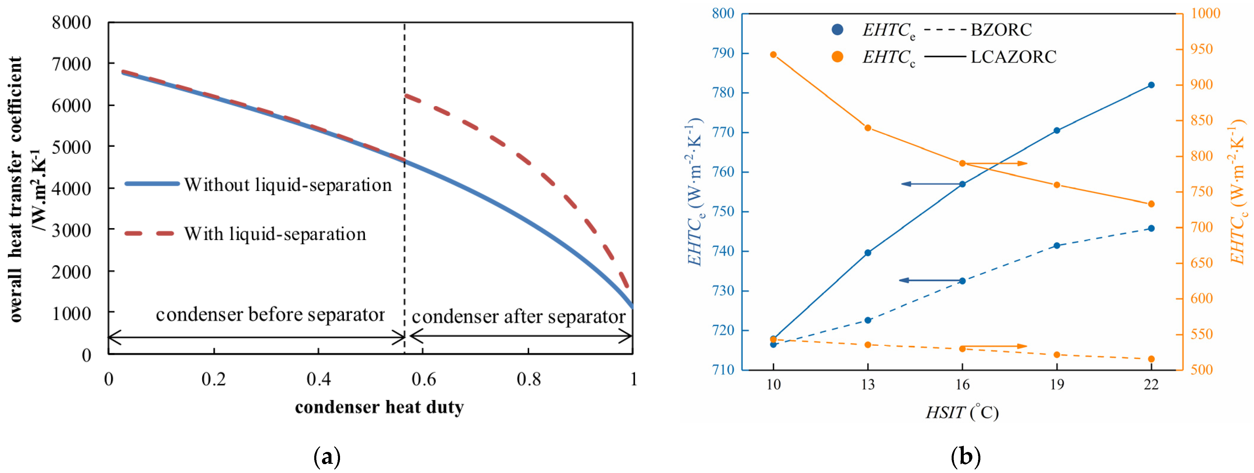
| [69] | Using liquid–vapor separation | Equivalent heat transfer coefficient | Enhance 34.93% |
| Ref. | Working Fluid | Partial Evaporating Type | Performance |
|---|---|---|---|
| [80] | Cyclopentane | Vapor regenerator | Thermodynamics |
| [81] | R245fa, R236ea, R600, R600a, R601, R601a | Separator | Thermodynamics, Thermo–economics |
| [79] | Propane, R227ea, R152a, R124, R142b, Butane, R245fa, R601a | Separator | Thermodynamics |
| [82] | Cyclopentane | Ejector/Vapor regenerator | Thermodynamics |
| [83] | R600, R600a, R601, R601a, R1234ze | Separator | Thermodynamics, Techno–economics |
Disclaimer/Publisher’s Note: The statements, opinions and data contained in all publications are solely those of the individual author(s) and contributor(s) and not of MDPI and/or the editor(s). MDPI and/or the editor(s) disclaim responsibility for any injury to people or property resulting from any ideas, methods, instructions or products referred to in the content. |
© 2023 by the authors. Licensee MDPI, Basel, Switzerland. This article is an open access article distributed under the terms and conditions of the Creative Commons Attribution (CC BY) license (https://creativecommons.org/licenses/by/4.0/).
Share and Cite
Lu, P.; Liang, Z.; Luo, X.; Xia, Y.; Wang, J.; Chen, K.; Liang, Y.; Chen, J.; Yang, Z.; He, J.; et al. Design and Optimization of Organic Rankine Cycle Based on Heat Transfer Enhancement and Novel Heat Exchanger: A Review. Energies 2023, 16, 1380. https://doi.org/10.3390/en16031380
Lu P, Liang Z, Luo X, Xia Y, Wang J, Chen K, Liang Y, Chen J, Yang Z, He J, et al. Design and Optimization of Organic Rankine Cycle Based on Heat Transfer Enhancement and Novel Heat Exchanger: A Review. Energies. 2023; 16(3):1380. https://doi.org/10.3390/en16031380
Chicago/Turabian StyleLu, Pei, Zheng Liang, Xianglong Luo, Yangkai Xia, Jin Wang, Kaihuang Chen, Yingzong Liang, Jianyong Chen, Zhi Yang, Jiacheng He, and et al. 2023. "Design and Optimization of Organic Rankine Cycle Based on Heat Transfer Enhancement and Novel Heat Exchanger: A Review" Energies 16, no. 3: 1380. https://doi.org/10.3390/en16031380