Review

Revisiting the Deep Geothermal Potential of the Cheshire Basin, UK

by
Christopher Simon Brown
James Watt School of Engineering, University of Glasgow, Glasgow G12 8QQ, UK
Energies 2023, 16(3), 1410; https://doi.org/10.3390/en16031410
Submission received: 10 November 2022 / Revised: 16 December 2022 / Accepted: 25 January 2023 / Published: 31 January 2023

Abstract

:
Deep geothermal energy can aid in the decarbonization of heat within the UK; this is required to meet net zero carbon emissions targets by 2050. The Cheshire Basin represents a significant opportunity for the development of deep geothermal resources; there are vast quantities of high permeability sandstones in hydraulic continuity, with temperatures favorable for direct heat use and, potentially, for power generation. Newly produced basal temperature maps in this study indicate the likely maximum temperatures for the basin, with the hottest temperature expected to be between 100 and 131.2 °C in the Crewe area. There have also previously been a range of estimates highlighting a geothermal resource within the basin to be in the region of 44.1 to 75 × 1018 J; however, previous estimates for heat in place are limited to simple volumetric or geometrical constraints. Therefore, this paper uses digitized depth and temperature maps to provide new estimates for the heat in place. Results suggest the resource has been underestimated and there is a need for more detailed evaluation. Depending on the geothermal gradient, the resource could be between 91 and 144 × 1018 J (1.26 to 1.45 × 10¹⁷ J/km2). Although there is a significant amount of heat in place, geological issues preventing development remain, such as the uncertainty in the quality of the reservoir at depth due to data limitations and the lateral continuity of the Manchester Marls Formation, which could act as a barrier to flow. Nevertheless, further regional assessment of the basin and data acquisition is required to build confidence in the reservoir quality and reduce uncertainty. This could unlock the basin for geothermal development.

1. Introduction

Geothermal energy has the potential to aid in the decarbonization of heat by providing a clean, weather-independent, constant base load of energy. Internationally, the use of geothermal energy is growing with the worldwide installed capacity reaching 15.95 GWe [1]. However, in the UK, 73% of spatial heating is supplied by gas and 10% by oil [2]; therefore, there is significant scope for geothermal resources to match the high demand for heat on a national level. This is similar to Europe where 75% of heating and cooling is supplied by fossil fuels [3]. It has been suggested the UK’s geothermal resources could provide heat for 100 years based on current consumption rates [4]. This in turn will help to meet government set net-zero carbon emissions targets.
There are vast, largely untapped, deep geothermal resources within the UK, predominantly associated to (1) hot-dry rocks (HDRs) and (2) hot sedimentary aquifers (HSAs). In this study, deep geothermal resources are presumed to be at depths >500 m to be in line with past renewable heat incentives and authors for UK case studies [5]. Deep projects are likely to have significant upfront costs (associated to drilling wells), but the development of deep geothermal resources could save significant amounts of money in contrast to fossil-fueled schemes [6].
HDRs are currently being explored and developed in the south of England, targeting permeable, natural fractures in the Cornubian Batholith [7,8,9,10]. There is also significant potential in northern England, associated to the North Pennine and Lake District Batholiths [11,12]. HSA resources in the UK are associated to deep geothermal Mesozoic Basins, with resources estimated to be between 201 and 328 × 1018 J [13,14,15,16,17]. In England and Wales, these include the Worcester, Eastern England, Wessex and Cheshire Basins (Figure 1) [17,18]. Despite the significant resource base, at present, only one deep HSA is being developed as a conventional resource; this is at Southampton (Wessex Basin) where a single borehole has been producing fluid at ~75 °C with a flow rate of 10–15 L/s from the Sherwood Sandstone Group for the last ~20 years [19,20].
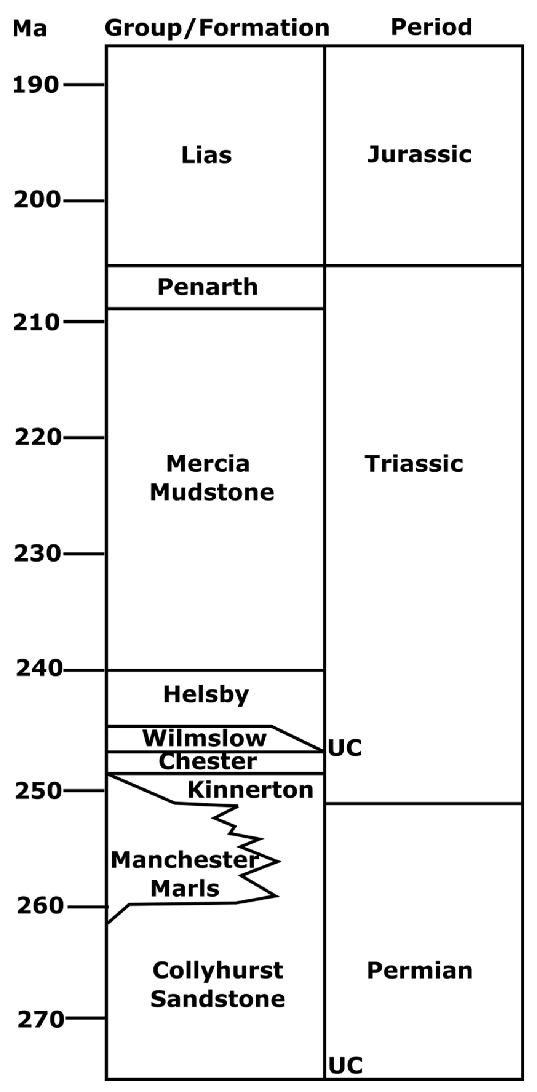
Whilst there are significant resources associated to HDRs and HSAs, the development of deep geothermal resources remains in its infancy. The barriers preventing development include, but are not limited to, a lack of infrastructure (district heat networks), a high level of risk due to a lack of data and gaps in knowledge [21], and issues around a lack of resource licensing, among others. This paper looks to assess the geothermal potential of the Cheshire Basin and its suitability for development. The Cheshire Basin consists of a clastic sequence of Permo-Triassic Sandstones, capped by an insulating mudstone unit (Figure 2). Sediment infill thickness within the basin reaches up to 4.5 km [22]. It is located in northwest England, stretching 100 km north to south and 55 km east to west, covering over 3500 km2 [21,23]. The basin’s resources have been highlighted for their high potential in past work due to the following: (1) 23% of the UK’s geothermal resources from HSAs are located within the basin, (2) the HSAs have high-quality hydraulic properties and significant thicknesses, (3) temperatures may reach >100 °C in the central parts of the basin, (4) there is a demand for heat at the surface coinciding with the higher temperature resources and (5) infrastructure in the form of a heat network is being developed at the surface level in Crewe [13,23,24,25].
Therefore, in this paper, the key objective was to investigate the potential for the development of the geothermal resource within the Cheshire Basin. This was achieved by calculating the heat in place using new digitized basin depth maps with the adapted volumetric method described by Brown [12] which considers digitized geometry. Past geothermal resource estimates have been based on simplifications, such as constant reservoir volume [16], or low temperatures and high recovery factors [13]. The hydraulic properties of reservoirs were also analyzed based on values from the literature to indicate a range of likely flow properties at depth, and basal temperature maps were also produced. This study focuses on the potential for direct heat use or power generation through open-loop methods. It is worth noting that alternatively a heat pump could be used to allow the use of lower temperatures from open-loop systems, or closed-loop deep borehole heat exchangers [26,27,28].

2. Geological Overview

The Cheshire Basin is a Permo-Triassic Basin that formed following the rifting of Pangaea and the breakup of Laurasia [29,30]. Variscan orogenic compression in the Late Carboniferous was followed by extensional collapse in the Permian and resulted in the formation of basins across much of Europe [31]. The basin is an asymmetrical half graben with infill constrained in the east by the Wem–Red Rock fault system [32] and the west by onlapping strata onto the basement [33]. Two distinct sets of faults have been identified from seismic analysis, the first consisting of sub-planar small extensional faults with throws of 100–500 m and the second with larger deeper faults (throws of 500–2500 m) separating the basin into a series of tilted fault blocks [23,34]. The aforementioned studies on fault analysis also highlighted three trends in fault orientation: northeast to southwest, north to south and northwest to southeast.
Sedimentary infill (Figure 2) is predominantly composed of a succession of fluvial and aeolian sandstones which were sourced by the Variscan Orogeny, overlain by a series of mudstones deposited in the Late Triassic and Jurassic during marine transgression [22,35,36,37]. Recent deposits consist of superficial Quaternary rocks from the last glacial period. These consist of granular deposits underlying sheets of till [23].
The most basal unit is the Permian Collyhurst Sandstone Formation which is an arenaceous sandstone laying unconformably over Westphalian rocks [38,39]. It is similar in character to the Kinnerton Sandstone Formation and they are often in hydraulic continuity to the south of the basin. To the north, the Collyhurst Sandstone Formation is overlain by the Manchester Marls Formation which thins southward. The Manchester Marls Formation was deposited during a minor marine incursion in the Permian [22].
The Manchester Marls Formation is overlain by the Triassic Sherwood Sandstone Group; this consists of the Kinnerton Sandstone Formation, the Chester Formation, the Wilmslow Sandstone Formation and the Helsby Formation. The Kinnerton Sandstone Formation was deposited in an aeolian environment and consists of fine to coarse grained sandstone [40], typically with high quality intergranular porosity identified in shallow boreholes [13,41]. The Chester Formation was deposited in the Early Triassic through braided river systems and is dominated by orthoquartzitic sandstones and conglomerates [22,38,40]. The Wilmslow Sandstone Formation is a poorly cemented sandstone succeeding the Chester Formation conformably [42]. It consists of fine to medium grained poor-quality sandstone with the lowest parts of the formation dominated by silicified layers [13,43]. The Helsby Sandstone Formation is the upper most unit of the Sherwood Sandstone Group. It overlies the Wilmslow Sandstone Formation unconformably due to erosion during a period of Triassic uplift [13,43]. The Helsby Sandstone Formation was deposited in aeolian to fluvial conditions and is characterized by large cross-bedded sandstone interbedded with fine grained muddy sandstone [44].
The thick succession of sandstone outlined above is confined by a thermally insulating mudstone sequence (Mercia Mudstone, Triassic Penarth and Jurassic Lias Groups).
Figure 2. Stratigraphy of the basin fill. Developed from Plant et al. [23]. Note UC = unconformity.
Energies 16 01410 g002

3. Geothermal Reservoirs

As highlighted in the previous section, multiple sandstone formations were deposited in the Cheshire Basin and are often in hydraulic continuity. These include the Helsby Formation, the Wilmslow Sandstone Formation, the Chester Formation, the Kinnerton Sandstone Formation and the Collyhurst Sandstone Formation. They are prolific aquifers at shallow intervals and this section aims to investigate their potential for geothermal development at depth, by considering hydraulic properties, thicknesses and thermal data obtained from wells. While the aquifers offer encouragment for development, there are regional and local obstacles which present barriers to flow. These are a result of variations in rock properties associated to localised lithological variations due to a change of depositional conditions, mineral precipitation (silicification in the Wilmslow Sandstone Formation) and lateral discontinuity of formations (such as the thinning of the Manchester Marls Formation to the south and Kinnerton Sandstone Formation to the north). A range of hydraulic properties have been listed in the literature and they range considerably (selected examples are listed in Table 1 and Table 2). Data listed by Plant et al. [23] is predominantly from outcrop studies, resulting in better hydraulic properties, whilst those in Downing and Gray [13] include both outcrop and geophysical log/core data. Therefore, the lower end of data highlighted in Table 2 is from logs at depths.
There is a large range in values, but the sandstone formations show promising intergranular permeabilties. Permian aquifers can be capabale of producing yields of 20–30 L/s from large diameter boreholes when formations are at shallow intervals [23]. Similarly, Triassic aquifers at shallower depths are typically used for groundwater, where large diameter boreholes can commonly discharge 50 L/s and sometimes exceed 100 L/s [23]. However, with depth the Permian to Early Triassic sandstones show reduced permeabilities and porosities due to cementation and the formation of secondary clay materials [13]. Others have suggested in the Kinnerton Sandstone Formation specifically that the porosity reduction is due to the degree of sorting, rather than cementation [45].
The Chester Formation also appears to be have good quality hydraulic properties at outcrop, but these reduce with depth implying the reservoir would be less-suitable for development as a HSA. The Wilmslow Sandstone Formation is distinctly split into an upper porous part and a cemented, sillicified bottom. The higher and poorer quality properties can, therefore, be correlated to these sections. Finally, the Helsby Formation also has high-quality properties that are associated to the depositional environments; lower-members are of aeolian origin and are more porous [46]. Local to regional scale variations in heterogeneity caused by fluvial to aeolian successions can impact fluid pathways [47].
Table 1. Table of hydraulic conductivities taken from a range of literature sources. Developed from Allen et al. [45], Downing and Gray [13], Plant et al. [23].
FormationHydraulic Conductivity (m/d)
Reference[23][13] *[45]
Helsby Sandstone Formation2.5–103.43.1 × 10−4–15
Wilmslow Sandstone Formation6 × 10−3–60.92.6 × 10−4–13
Chester Formation0.5–52.62.5 × 10−4–15
Kinnerton and Collyhurst Sandstone Formation>10.93.7 × 10−5–10
* Note values from Downing and Gray [13] are approximated hydraulic conductivity values for where probability distribution of 50% and the range of values in this source includes Colter and Ebburn [48], Lovelock [41] and Skinner [49].
Water salinity increases with depth within the basin and is caused by the dissolution of halite in the Mercia Mudstone Group. Plant et al. [23] analyzed fluids, and modelled regional groundwater flow to predict salinity concentrations within the basin. The predicted total dissolved solids within water ranges between 14 and 170 g/L (obtained from Prees-1, Burford, Elworth and Knutsford boreholes). In shallow strata, the salinity concentration is expected to be 20–30 g/L, whilst at depth 60–80 g/L is predicted. This is due to density driven flow downwards with salt sourced from the Mercia Mudstone Group. A high salinity content could pose issues during production through well clogging and scaling within the heat exchanger [50].
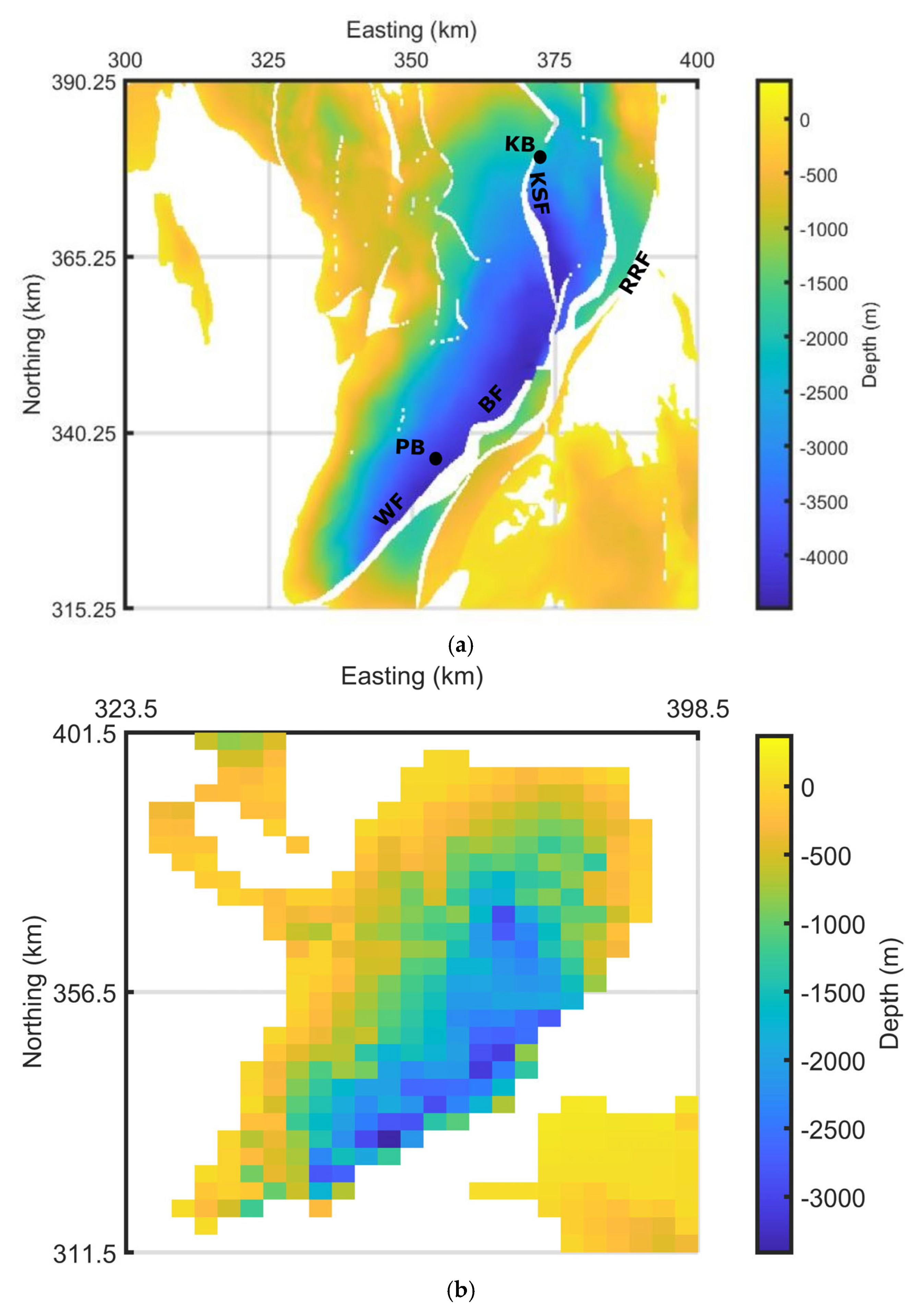
The basin depth increases towards the central-eastern part of the basin due to the controlling Wem–Red Rock Fault located on the eastern margin (Figure 3). This results in an accumulation of over 4.5 km of sediment infil thickness, largely composed of Permo-Triassic sandstone reservoirs. These are highlighted in Figure 3a, which is a depth map to the base of the Permian, defined as an unconformity marking post Variscan rocks after the orogeny (e.g., [51,52]). Limited deep wells have been drilled within the basin, yet two exceed 3 km depth. These are the Prees-1 (SJ53SE3) and Knutsford-1 (SJ77NW4) boreholes (Figure 3). The Prees-1 borehole was drilled in 1972 to 3828.28 m [53], where no Manchester Marls Formation was encountered suggesting the thinning of the formation, or a gradational transition into sandstone. The Knutsford-1 borehole was drilled in 1974, reaching 3045.7 m. The well log highlighted that the petroleum system was inadequate for development, but that the reservoirs were of good quality [54]. The well’s primary aim was to target the Collyhurst Sandstone Formation and test if the Manchester Marls Formation was present as a cap rock for hydrocarbon prospecting. The Manchester Marls Formation was predominantly sandy and minor beds of mudstone less than 10 m in thickness were identified. Whilst the cap rock was of insufficient quality to trap hydrocarbons, the report did highlight that the Permian and Triassic rocks had fair to good porosties, giving scope for geothermal development. Both wells highlighted that the thickness of the sandstone’s reservoirs increases to the central-to-southeastern part of the basin with the combined reservoir thickness reaching >1600 m and >2000 m, recorded at the Prees-1 and Knutsford boreholes, respectively (e.g., see [38,55]). Any future geothermal development must also consider difficulties caused by potential gas/oil sourced from Dinantian, Namurian and Westphalian strata [23].
Several temperature logs from deep wells across the basin have been recorded; however, these are likely to be lower than the true temperature by several degrees, due to data being mostly uncorrected [21,56]. These are highlighted in Figure 4 and support the theory that temperatures could exceed 100 °C in the central part of the basin. The data indicates a likely geothermal gradient closer to 20 °C/km. This is similar to the estimates for heat flow (52 mWm−2) and gradients from other literature [13,57]. Busby [17], in contrast, suggests a 27 °C/km geothermal gradient which appears far higher than the data suggests and may be based upon corrected values, or a wider range of data which is not available in the public domain.
Table 2. Table of porosities taken from a range of literature sources. Developed from Allen et al. [45], Downing and Gray [13], Plant et al. [23].
FormationPorosity (%)
Reference[23][13][45]
Helsby Sandstone Formation25–3014–3020–33
Wilmslow Sandstone Formation13–308–306–35
Chester Formation20–309–3011–29
Kinnerton and Collyhurst Sandstone Formation20–249–1713–32
Figure 3. (a) Depth map to the base of the Cheshire Basin. Resolution of 250 m spacing. Derived from South West Pennines Model, Lithoframe 3D model—250K data, 13,160 km2 scale BGS Digital Data under License 2022/067-V2 British Geological Survey © and Database Right UKRI. All rights reserved [58]. (b) Depth map of the base of Triassic sandstones. Resolution of 3 km spacing. Contains British Geological Survey materials Copyright NERC 2022 [59]. Note borehole localities shown as black circles. Abbreviations as follows: PB = Prees-1 borehole, KB = Knutsford-1 borehole, WF = Wem Fault, BF = Bridgemere Fault, KSF = Kings Street Fault and RRF = Red Rock Fault. See Plant et al. [23] for further structural features. For location of the map see area highlighted in Figure 1.
Energies 16 01410 g003
Figure 4. Temperature vs. depth plot. Data collated from Burley [60], Busby [17], Hirst et al. [21], Plant et al. [23]. Note depth is meters below ground level and the data.
Energies 16 01410 g004
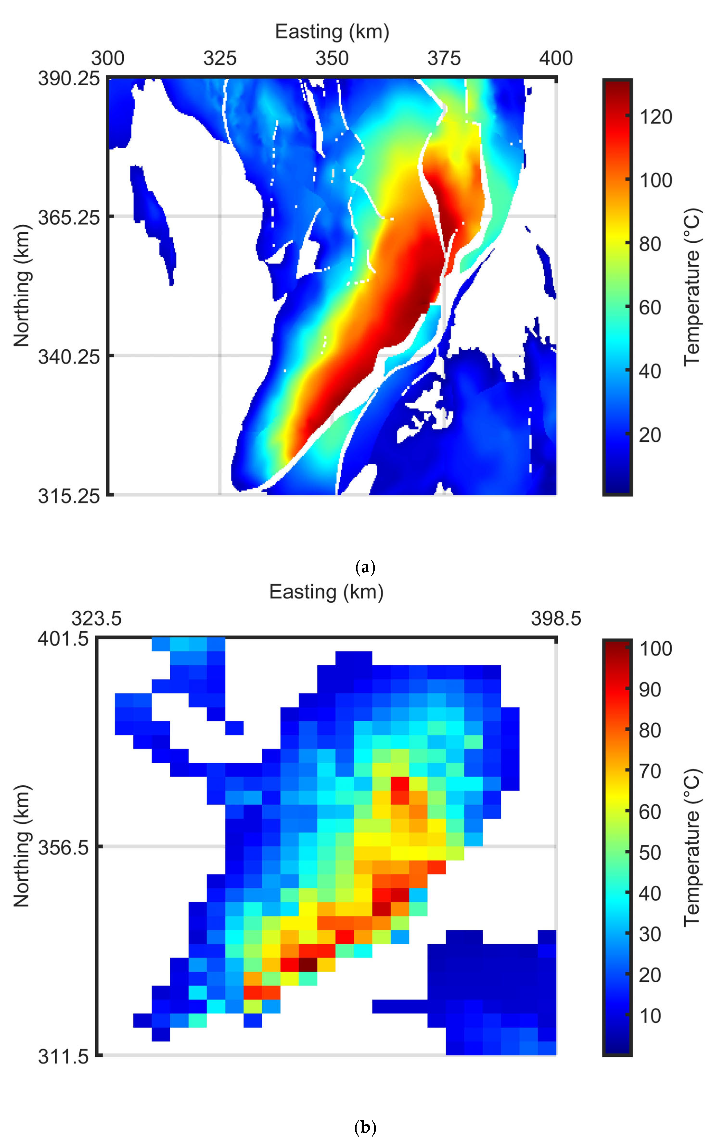
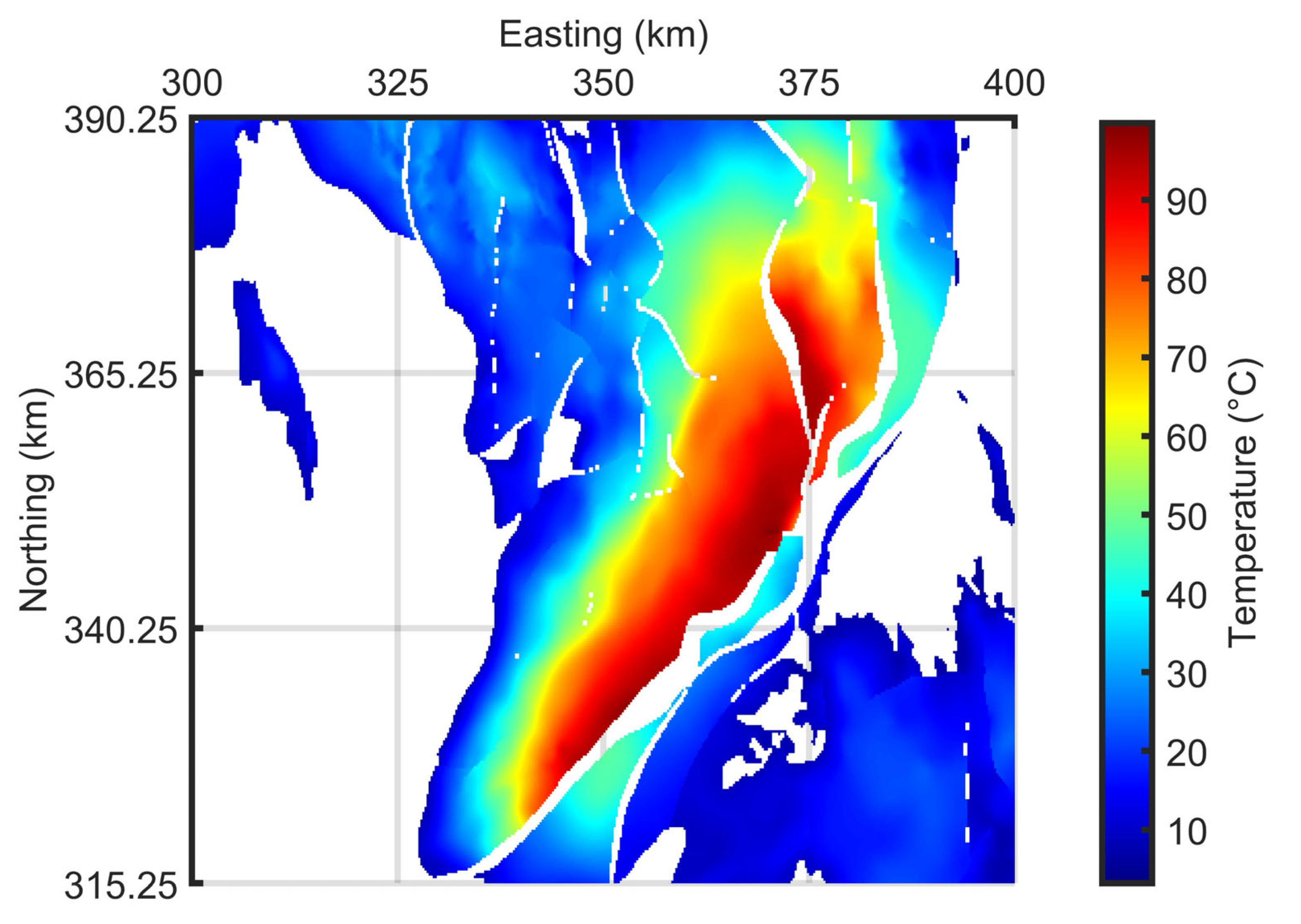
Reservoirs in the basin are more suited to direct heat use due to the lower temperatures typically encountered (Figure 4, Figure 5, Figure 6 and Figure 7), but the possibility does remain to exploit the most basal sandstones for power generation. As highlighted in Figure 5, temperatures in excess of 100 °C may be recorded at the base, giving scope for power generation. The temperature map in Figure 5 was plotted using a linear relationship between depth and temperature. A constant surface temperature of 10 °C was used with a gradient of 27 °C/km as reported by Busby [17]. The highest temperatures correspond to the deepest sandstones and tend to be located along the Wem–Red Rock Fault. The maximum temperature recorded was 131.2 °C. Similarly, the base of the top of the Permian is shown in Figure 5b and temperatures appear to exceed 100 °C in the central to southeastern part of the basin. While Figure 5 indicates that temperatures may exceed 100 °C at the top and base of the Permian sandstones, it is worth noting the distribution of temperature density is limited in contrast to the low temperatures encountered over much of the basin (Figure 6). Additionally, the geothermal gradient used for linear extrapolation of the temperature at depth appears high in contrast to the data in Figure 4 (albeit the data in Figure 4 is mostly uncorrected Hirst [56]), so could be overly optimistic. Figure 7 provides approximations of basal temperature using a conservative geothermal gradient of 20 °C/km. It shows temperatures at 4.5 km barely reaches 100 °C. It is likely that the true basal temperature will be within the range of ~100 to ~130 °C at 4.5 km.

4. Geothermal Resources

4.1. Methodology

Several authors have estimated the geothermal resource available within the Cheshire Basin, providing a range of values. These are summarized in Table 3. The heat in place or geothermal resource ( H i p ) can be calculated using the volumetric method (e.g., [61,62]):
H i p = C f ρ f + 1 C m ρ m V T r T o
where is porosity, C f is the specific heat capacity of the fluid, ρ f is the density of the fluid, C m is the specific heat capacity of the matrix, ρ f is the density of the matrix, V is the volume, T r is the average reservoir temperature and T o is the temperature at the ground level.
As highlighted in Table 3, the estimates of the geothermal resource differ quite significantly. Jackson [16] estimated heat available for direct-uses with a reduced area in contrast to the other estimates of Downing and Gray [13] and Rollin et al. [14]. There are also differences in volume constraints, reservoir temperature and methods.
Table 3. Geothermal resource estimates from literature: 1 EJ = 1 × 10¹⁸ J. Data collated from Downing and Gray [13], Jackson [16], Rollin et al. [14].
ContentGeothermal Resource (EJ)
-[13][16] *[14]
Triassic Sandstones3044.136
Permian Sandstones3539
* Not for Jackson [16] the Permo-Triassic rocks are undifferentiated.
In this study, digitalized depth data allows new estimations of the undifferentiated total resource. By using the basal temperature maps produced in Figure 5a and Figure 7 the approximate resource can be estimated. In this study a conservative gross rock thickness of 500 m was used after Jackson [16]; however, as previously discussed, the thickness varies across the basin and in the center the thickness can reach over 2 km (e.g., in the Knutsford-1 borehole). This is likely to lead to underestimations of resources in the central part of the basin. The resource for each grid block (250 m × 250 m × 500 m) was determined and then the total resource was calculated. The average temperature within a grid block was calculated from the basal temperature and respective geothermal gradient. A reservoir temperature cut-off of 60 °C was implemented and delimits the area of the geothermal resource (Figure 5a and Figure 7). This was set as a minimum required for direct-heat use applications for older generation heat networks. Fourth generation district heating or newer can use far lower operating temperatures due to their design (e.g., [63]). Additionally, in reality, lower temperature uses can be used within the food industry, greenhouses and balyneology [64]. Potentially, a cascade system could be incorporated to maximize the heat use (e.g., [65]). Therefore, the results are likely lower end estimates. Other parameters are also listed in Table 4.
The recoverable energy ( E r ) is often significantly less than that of the total resource. It can be calculated using a recovery factor ( R ) as (e.g., [66,67]):
E r = R × H i p
whilst the technical potential ( T P ) for a lifetime of a system can be calculated:
T P = E r t
In this study the recovery factor was limited to 5% and the lifetime (t) to 30 years. The recovery factor is a conservative estimate, as some authors use a recovery factor up to 25% for the UK HSAs [13]; however, this is extremely high as there are limited data on aquifer performance at depth in the Cheshire Basin and it is likely hydraulic properties at depths will reduce limiting the value. The permeability and porosity could, therefore, influence the recovery of heat, or alternatively, the configuration of wells can influence the sweeping effect [13]. In other world estimates, a 1% value is used and it is recommended for studies with limited data more conservative recovery factors are chosen [68].
Table 4. Parameter input for quasi-3D geothermal resource calculation. Sources of data input were obtained from Brown et al. [69], Jackson [16], Plant et al. [23].
ParameterValueUnitsReference
Surface Temperature10°C-
Porosity20%[16]
Specific Heat Capacity of Fluid4200Jkg−1 °C−1[69]
Density of Fluid1050kg/m3[23]
Specific Heat Capacity of Matrix1100Jkg−1 °C−1[69]
Density of Matrix2450kg/m3[69]

4.2. Results

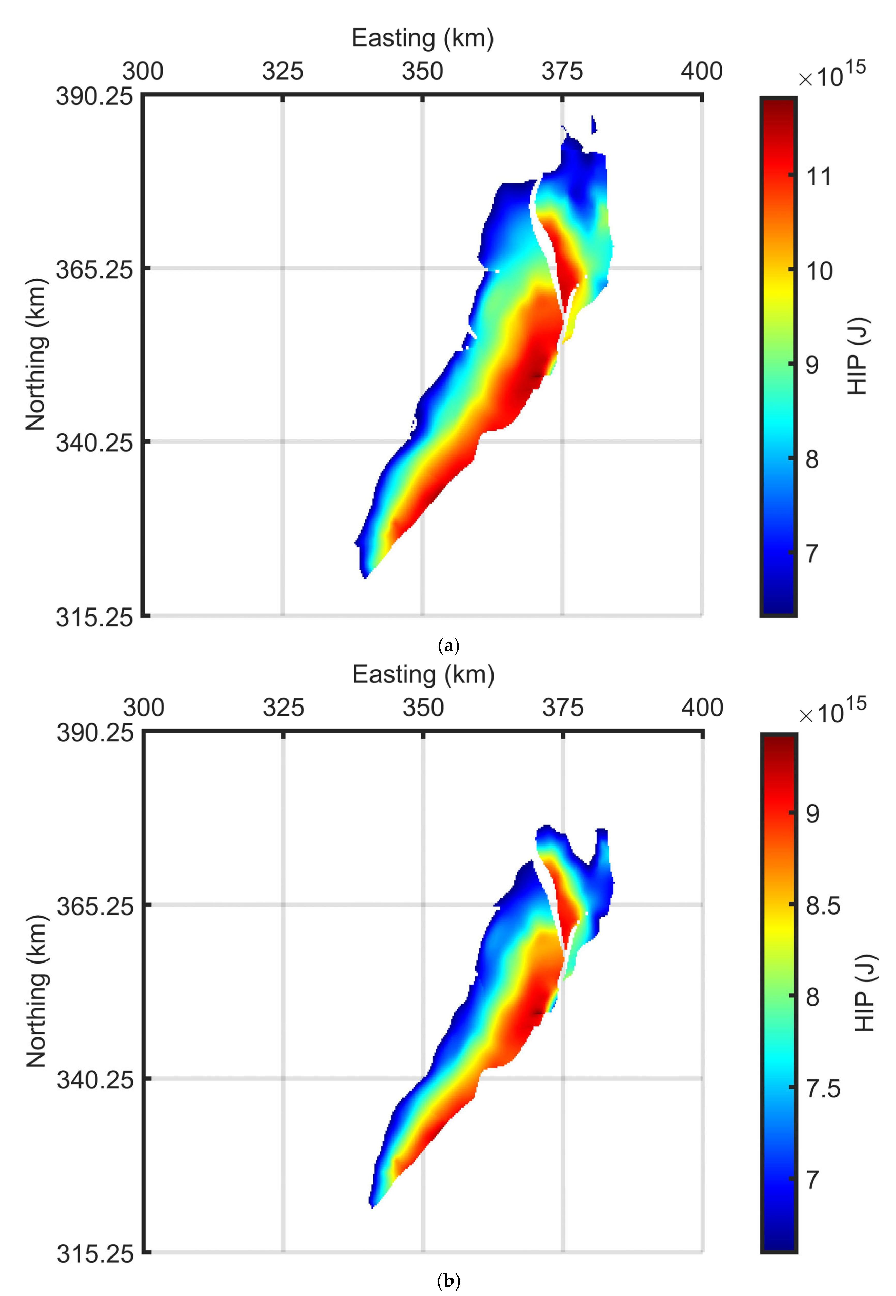
The resource estimate varies between 91 and 144 × 1018 J for geothermal gradients of 20 and 27 °C/km, respectively. As one might expect, the increase in resource corresponds to the deepest and hottest parts of the basin (Figure 8). This is due to the linear relationship established between depth and temperature. The estimate for the resource is significantly more than past estimates and could be due to new digitized data providing better geometrical constraints. Interestingly, the recoverable energy is less at 4.6 and 7.2 × 10¹⁸ J for the respective geothermal gradients used. This is due to the conservative recovery factor used, which is in contrast to other authors who used values of 0.1 and 0.25 [13]. The technical potential also reflects this (Table 5).
The 20 °C/km thermal gradient resulted in an areal extent of 721 km2 being used, whilst for 27 °C/km the total area was 995 km2. This was calculated for both geothermal gradients using the 60 °C cut-off. Areal, temperature and thickness values vary in comparison with those used for past calculations, which explains the larger values for geothermal resource estimates. This indicates that previous estimates of the resource could be significantly underestimated for the Cheshire Basin and future work should look to focus on regional 3D modelling for better geometrical distributions and thicknesses of individual reservoir layers (e.g., using methods similar to Howell et al. [11] and Brown [12]) or, alternatively, future work could look to other methods of evaluating potential, such as investigating the geothermal capacities (i.e., per doublet system) (e.g., see Agemar et al. [64]). The work by Agemar et al. [64] also suggested presenting resources per km2; using this method the resource for the basin is 1.26 to 1.45 × 10¹⁷ J/km2.
Figure 8. (a) Heat in place (HIP) map of the Cheshire Basin using a geothermal gradient of 27 °C/km. Resolution of 250 m spacing. (b) Heat in place (HIP) map of the Cheshire Basin using a geothermal gradient of 20 °C/km. Resolution of 250 m spacing. Derived from South West Pennines Model, Lithoframe 3D model—250K data, 13,160 km2 scale BGS Digital Data under License 2022/067-V2 British Geological Survey © and Database Right UKRI. All rights reserved [58].
Energies 16 01410 g008
Table 5. Geothermal potential assessment: 1 EJ = 1 × 10¹⁸ J.
Geothermal Gradient (°C/km) H i p   ( EJ ) E r   ( EJ ) T P   ( GW th )
20914.64.8
271447.27.6
The uncertainty in porosity values from the literature can also be addressed. By using the minimum and maximum values for porosity in Table 2, new resource estimates were calculated (Table 6). Greater porosity leads to variance in the total heat in place, recoverable energy and technical potential. This is further evidence that more detailed regional assessment is required using probabilistic methods.

5. Discussions

There is a strong potential for geothermal development within the Cheshire Basin due to high basal temperatures, the good hydraulic properties of the rocks and suitable infrastructure development at the surface level in Crewe, coinciding with greater rock thicknesses and higher temperatures. It has been suggested that a geothermal fed district heating scheme in Crewe has the potential to exploit heat in excess of 100 °C, generating 76 GWh of heat which could feed nearly 7000 homes and save up to 8000 tonnes of carbon savings per year [70]. There are also significant savings to be made in contrast to a fossil-fueled district heat network, with it being estimated that for production temperatures of between 67 and 86 °C that £43 to £71.5 million could be saved by using geothermal sources of heat [6].
The geothermal resource was considered in this study and compared with past estimates. As summarized by Busby [17], previous estimates by Rollin et al. [14] and Downing and Gray [13] used models based on aquifer geometry, assigning different volumes for different depths with corresponding average temperature values. They also used a minimum temperature cut-off of 40 °C and a base temperature of 10 °C. Furthermore, Downing and Gray [13] used a simplified equation which does not account for rock properties specific to the Cheshire Basin (such as porosity, density and specific heat capacity). Jackson [16], in contrast, used a total undifferentiated volume of reservoir and a cut-off of 65 °C, with a base temperature of 25 °C. The average reservoir temperatures for other studies were generally lower than in this, contributing to the reduced resource estimate. In this study, the geothermal resource was calculated for a series of grid blocks before being taken for the whole area. The heat in place was estimated to range between 91 and 144 × 1018 J. Whilst this should be used to give an indication of the geothermal resources, there is still room for more detailed modelling using 3D geometrical data from seismic analysis as the current estimate uses a constant thickness of aquifer which does not reflect the thickening of sandstones to the center of the basin, or the thinning to the west. Therefore, lower temperature resources were not considered. The varying thermal gradient under different geological formations should also be considered, as well as the correction for the surface elevation. Furthermore, there is uncertainty caused by the variations in porosity and permeability between individual aquifers (highlighted in Table 1 and Table 2). Simple considerations of the former (Table 6) highlight that there is a need for a probabilistic assessment of all parameters using Equations (1) and (2) in future studies. The sensitivity of such parameters can significantly influence results and outcomes.
More focused localized dynamic geothermal modelling of the basin has also been undertaken by Brown et al. [69], targeting a conventional single well system, similar to that currently working in Southampton. The work suggested that hydraulic conductivity and initial geothermal gradient pose significant geological risks due to the sensitivity shown by modelling. This is in agreement with the work of this study, which has highlighted that data for hydraulic conductivity is poorly constrained at depth and the varying geothermal gradients cited in the literature result in huge differences in resource calculations. As an alternative method of exploitation, deep borehole heat exchangers may be considered [28,71,72,73], but they would operate at a reduced capacity in contrast to open-loop systems and pose economic difficulties [74].
While there is significant potential, the Cheshire Basin remains underdeveloped, with studies limited to feasibility assessments [70,75,76]) or preliminary modelling where data is scarce [69,71]. As highlighted by Atkins [76] and Hirst et al. [21] significant exploration is required to reduce risk and uncertainty. Funding limitations remain an obstacle to development and as a result the area is still within a research phase without any deep developments occurring. Hirst [56] made analogies to the East Irish Sea Basin, suggesting the similar depositional environment, burial history, diagenesis and structural history made it a candidate for supplementing data.
Finally, while the focus of this paper was deep HSAs, the shallow rocks covering the basin and much of the UK offer significant scope for developments to exploit heat using ground sourced heat pumps (e.g., [77,78,79]). Engineered or enhanced geothermal systems could also exploit deep basement units across the UK for power generation [80].

6. Conclusions

This study has revisited and highlighted that there is significant potential to exploit the Cheshire Basin for both direct heat use and potential power generation. Vast quantities of Permo-Triassic reservoirs with high-quality hydraulic properties are distributed across the basin at depths of up to 4.5 km and at temperatures up to 131.2 °C. Although the high temperature basal depth value is a likely maximum value calculated using the 27 °C/km geothermal gradient from Busby [17], other values for heat flow and geothermal gradients in the Cheshire Basin are often quoted as being far lower. Infrastructure exists to exploit the heat directly in the Crewe area, with a district heat network under development. Further surface infrastructure is required to allow the resource to be developed to meet demand.
Modelling of the resource regionally and locally under development conditions has been undertaken in recent years. Previous regional modelling has shown the resource to be in the region of 44.1 to 75 × 1018 J [13,14,16], which corresponds to ~23% of the UKs resource available in low-enthalpy HSAs [25]. New estimates using digitized basin depth maps were produced in this study using an adapted volume method (similar to that of Brown [12]), highlighting that the resource appears to have been underestimated. Under conservative estimations and a reduced thickness of the sandstone reservoir, the resource was estimated to be between 91 and 144 × 1018 J in this study. The former value associated to a geothermal gradient of 20 °C/km and the latter to a gradient of 27 °C/km. This indicates the geothermal resource and thermal maps should be revisited in future work using both deterministic and probabilistic methods to analyze the data with new geometrical/thickness/thermal data. Furthermore, other prospective basins in the UK could be underestimated in terms of geothermal resource. Therefore, there is potential for the geothermal resource base of the UK to be revisited nationally.
Regionally, although the resource appears significant, local geological issues which could influence production exist, such as sensitivity to hydraulic conductivity, the lateral continuity of the Manchester Marls Formation and variable geothermal gradients [69]. As a result, an alternative method for exploitation may be to utilize deep borehole heat exchangers which operate at a reduced risk in a closed-loop system and have been modelled to show that heat extraction rates of ~300 kW can be produced [71]. This is, however, a far lower capacity in contrast to an open system, where rates of ~3 MW could be achieved [69].
To encourage further development within the basin more data is needed. Hirst [56] investigated data availability within the Cheshire Basin. They stated that ~95% of borehole data is shallow (under 50 m) or confidential with minimal records. Where data is available and includes hydraulic properties, it is typically located away from the central deepest parts of the basin around the Crewe area. Furthermore, specific data to the Collyhurst Sandstone Formation is rarely reported and it is typically undifferentiated from the Kinnerton Sandstone Formation. As only two wells penetrate past 3 km, more data is needed at depth testing the sandstones hydraulic and thermal properties at a series of intervals to establish the most productive aquifers in in situ conditions. If more data can be acquired to support development then the ~2 km thickness of sandstones may be exploited to support heat decarbonization in the UK and potentially be used for power generation.

Funding

This research received no external funding.

Data Availability Statement

Derived from South West Pennines Model, Lithoframe 3D model—250K data, 13,160 km2 scale BGS Digital Data under License 2022/067-V2 British Geological Survey. © and Database Right UKRI. All rights reserved.

Acknowledgments

I would like to thank Lucy Brown for proofreading the manuscript and their continual support. I would also like to thank three anonymous reviewers and the editor for their constructive comments and feedback which has helped to improve the paper. I also appreciate BGS for providing the data.

Conflicts of Interest

The author declares no conflict of interest.

References

  1. Huttrer, G.W. Geothermal power generation in the world 2015–2020 update report. In Proceedings of the World Geothermal Congress, Reykjavik, Iceland, 27 April–1 May 2020; Volume 1. [Google Scholar]
  2. BEIS. Opportunity Areas for District Heating Networks in the UK. National Comprehensive Assessment of the Potential for Efficient Heating and Cooling. 2021. Available online: https://assets.publishing.service.gov.uk/government/uploads/system/uploads/attachment_data/file/1015585/opps_for_dhnnca_hc.pdf (accessed on 24 January 2023).
  3. Lindroos, T.J.; Mäki, E.; Koponen, K.; Hannula, I.; Kiviluoma, J.; Raitila, J. Replacing fossil fuels with bioenergy in district heating–Comparison of technology options. Energy 2021, 231, 120799. [Google Scholar] [CrossRef]
  4. Gluyas, J.; Adams, C.; Busby, J.; Craig, J.; Hirst, C.; Manning, D.; McCay, A.; Narayan, N.; Robinson, H.; Watson, S.; et al. Keeping warm: A review of deep geothermal potential of the UK. Proc. Inst. Mech. Eng. Part A J. Power Energy 2018, 232, 115–126. [Google Scholar] [CrossRef] [Green Version]
  5. Watson, S.M.; Falcone, G.; Westaway, R. Repurposing hydrocarbon wells for geothermal use in the UK: The on-shore fields with the greatest potential. Energies 2020, 13, 3541. [Google Scholar] [CrossRef]
  6. Brown, C.S.; Cassidy, N.J.; Egan, S.S.; Griffiths, D. Thermal and Economic Analysis of Heat Exchangers as Part of a Geothermal District Heating Scheme in the Cheshire Basin, UK. Energies 2022, 15, 1983. [Google Scholar] [CrossRef]
  7. Baria, R.; MacPherson-Grant, G.; Baumgaertner, J.; Jupe, A.; Cowles, J. Engineered Geothermal Program in the UK. In Proceedings of the World Geothermal Congress, Bali, Indonesia, 25–29 April 2010. [Google Scholar]
  8. Curtis, R.; Ledingham, P.; Law, R.; Bennett, T. Geothermal energy use, country update for United Kingdom. In Proceedings of the European Geothermal Congress, Pisa, Italy, 3–7 June 2013; pp. 1–9. [Google Scholar]
  9. Somma, R.; Blessent, D.; Raymond, J.; Constance, M.; Cotton, L.; Natale, G.; Fedele, A.; Jurado, M.; Marcia, K.; Miranda, M.; et al. Review of Recent Drilling Projects in Unconventional Geothermal Resources at Campi Flegrei Caldera, Cornubian Batholith, and Williston Sedimentary Basin. Energies 2021, 14, 3306. [Google Scholar] [CrossRef]
  10. Farndale, H.; Law, R. An Update on the United Downs Geothermal Power Project, Cornwall, UK. In Proceedings of the 47th Workshop on Geothermal Reservoir Engineering, Stanford, CA, USA, 7–9 February 2022. [Google Scholar]
  11. Howell, L.; Brown, C.S.; Egan, S.S. Deep geothermal energy in northern England: Insights from 3D finite difference temperature modelling. Comput. Geosci. 2021, 147, 104661. [Google Scholar] [CrossRef]
  12. Brown, C.S. Regional geothermal resource assessment of hot dry rocks in Northern England using 3D geological and thermal models. Geothermics 2022, 105, 102503. [Google Scholar] [CrossRef]
  13. Downing, R.A.; Gray, D.A. (Eds.) Geothermal Energy–The Potential in the 495 United Kingdom; HMSO: London, UK, 1986. [Google Scholar]
  14. Rollin, K.E.; Kirby, G.A.; Rowley, W.J.; Buckley, D.K. Atlas of Geothermal Resources in Europe: UK Revision; Technical Report WK/95/07; British Geological Survey: Keyworth, UK, 1995. [Google Scholar]
  15. Pasquali, R.; O’Neill, N.; Reay, D.; Waugh, T. The geothermal potential of Northern Ireland. In Proceedings of the World Geothermal Congress 2010, Bali, Indonesia, 25–29 April 2010. [Google Scholar]
  16. Jackson, T. Geothermal Potential in Great Britain and Northern Ireland; Sinclair Knight Merz: Sydney, NSW, Australia, 2012. [Google Scholar]
  17. Busby, J. Geothermal energy in sedimentary basins in the UK. Hydrogeol. J. 2014, 22, 129–141. [Google Scholar] [CrossRef] [Green Version]
  18. Busby, J. Geothermal prospects in the United Kingdom. In Proceedings of the World Geothermal Congress 2010, Bali, Indonesia, 25–29 April 2010. [Google Scholar]
  19. Smith, M. Southampton energy scheme. In Proceedings of the World Geothermal Congress, IGA, Tokyo, Japan, 28 May–10 June 2000. [Google Scholar]
  20. Batchelor, T.; Curtis, R.; Busby, J. Geothermal Energy Use, Country Update for United Kingdom. In Proceedings of the World Geothermal Congress, Reykjavik, Iceland, 24–27 October 2021. [Google Scholar]
  21. Hirst, C.M.; Gluyas, J.G.; Adams, C.A.; Mathias, S.A.; Bains, S.; Styles, P. UK Low Enthalpy Geothermal Resources: The Cheshire Basin. In Proceedings of the World Geothermal Congress 2015, Melbourne, VIC, Australia, 19–25 April 2015. [Google Scholar]
  22. Naylor, H.; Turner, P.; Vaughan, D.J.; Boyce, A.J.; Fallick, A.E. Genetic studies of red bed mineralization in the Triassic of the Cheshire Basin, northwest England. J. Geol. Soc. 1989, 146, 685–699. [Google Scholar] [CrossRef]
  23. Plant, J.A.; Jones, D.G.; Haslam, H.W. (Eds.) The Cheshire Basin: Basin Evolution, Fluid Movement and Mineral Resources in a Permo-Triassic Rift Setting; British Geological Survey: Nottingham, UK, 1999. [Google Scholar]
  24. Routledge, K.; Williams, J.; Lehdonvirta, H.; Kuivala, J.-P.; Fagerstrom, O. Heat Network Mapping for Leighton West; Report Number: 298–692; Cheshire East Council: Crewe, UK, 2014. [Google Scholar]
  25. Brown, C.S. Modelling, Characterisation and Optimisation of Deep Geothermal Energy in the Cheshire Basin. Ph.D. Thesis, University of Birmingham, Birmingham, UK, 2020. [Google Scholar]
  26. Morchio, S.; Fossa, M. Thermal modeling of deep borehole heat exchangers for geothermal applications in densely populated urban areas. Therm. Sci. Eng. Prog. 2019, 13, 100363. [Google Scholar] [CrossRef]
  27. Beier, R.A.; Fossa, M.; Morchio, S. Models of thermal response tests on deep coaxial borehole heat exchangers through multiple ground layers. Appl. Therm. Eng. 2020, 184, 116241. [Google Scholar] [CrossRef]
  28. Brown, C.S.; Kolo, I.; Falcone, G.; Banks, D. Investigating scalability of deep borehole heat exchangers: Numerical modelling of arrays with varied modes of operation. Renew. Energy 2023, 202, 442–452. [Google Scholar] [CrossRef]
  29. Glennie, K.W. Permian and Triassic rifting in northwest Europe. Geol. Soc. London Spec. Publ. 1995, 91, 1–5. [Google Scholar] [CrossRef]
  30. Rowley, E.; White, N. Inverse modelling of extension and denudation in the East Irish Sea and surrounding areas. Earth Planet. Sci. Lett. 1998, 161, 57–71. [Google Scholar] [CrossRef]
  31. Woodcock, N.H.; Strachan, R.A. Geological History of Britain and Ireland; John Wiley & Sons: Hoboken, NJ, USA, 2009. [Google Scholar]
  32. Hough, E.; Schofield, D.; Pharaoh, T.; Haslam, R.; Loveless, S.; Bloomfield, J.P.; Lee, J.R.; Baptie, B.; Shaw, R.P.; Bide, T.; et al. National Geological Screening: Central England Region; British Geological Survey: Nottingham, UK, 2018. [Google Scholar]
  33. Bloomfield, J.P.; Moreau, M.F.; Newell, A.J. Characterization of permeability distributions in six lithofacies from the Helsby and Wilmslow sandstone formations of the Cheshire Basin, UK. Geol. Soc. London Spec. Publ. 2006, 263, 83–101. [Google Scholar] [CrossRef]
  34. Chadwick, R.A. Fault analysis of the Cheshire Basin, NW England. Geol. Soc. London Spec. Publ. 1997, 124, 297–313. [Google Scholar] [CrossRef]
  35. Rayner, D.H. Stratigraphy of the British Isles, 2nd ed.; Cambridge University Press: Cambridge, UK, 1981. [Google Scholar]
  36. Williams, G.D.; Eaton, G.P. Stratigraphic and structural analysis of the Late Palaeozoic–Mesozoic of NE Wales and Liverpool Bay: Implications for hydrocarbon prospectivity. J. Geol. Soc. 1993, 150, 489–499. [Google Scholar] [CrossRef]
  37. Wilson, A.A. The Mercia Mudstone Group (Trias) of the Cheshire Basin. Proc. Yorks. Geol. Soc. 1993, 49, 171–188. [Google Scholar] [CrossRef]
  38. Mikkelsen, P.W.; Floodpage, J.B. The hydrocarbon potential of the Cheshire Basin. Geol. Soc. London Spé;c. Publ. 1997, 124, 161–183. [Google Scholar] [CrossRef]
  39. Griffiths, K.J.; Shand, P.; Ingram, J. Baseline Report Series: 8. The Permo-Triassic Sandstones of Manchester and East Cheshire British Geological Survey Commissioned Report No. CR/03/265N; British Geological Survey: Nottingham, UK, 2003. [Google Scholar]
  40. Ambrose, K.; Hough, E.; Smith, N.J.P.; Warrington, G. Lithostratigraphy of the Sherwood Sandstone Group of England, Wales and South-West Scotland; British Geological Survey: Nottingham, UK, 2014. [Google Scholar]
  41. Lovelock, P.E.R. Aquifer properties of PermoTriassic sandstones in the United Kingdom. Geol. Surv. 1977, 56, 646–665. [Google Scholar]
  42. Barker, R.D.; Tellam, J.H. Fluid Flow and Solute Movement in Sandstones: The Onshore UK Permo-Triassic Red Bed Sequence; Geological Society of London: London, UK, 2006. [Google Scholar]
  43. Evans, D.J.; Rees, J.G.; Holloway, S. The Permian to Jurassic stratigraphy and structural evolution of the central Cheshire Basin. J. Geol. Soc. 1993, 150, 857–870. [Google Scholar] [CrossRef]
  44. Mountney, N.P.; Thompson, D.B. Stratigraphic evolution and preservation of aeolian dune and damp/wet interdune strata: An example from the Triassic Helsby Sandstone Formation, Cheshire Basin, UK. Sedimentology 2002, 49, 805–833. [Google Scholar] [CrossRef]
  45. Allen, D.J.; Brewerton, L.J.; Coleby, L.M.; Gibbs, B.R.; Lewis, M.A.; MacDonald, A.M.; Wagstaff, S.J.; Williams, A.T. The Physical Properties of Major Aquifers in England and Wales; British Geological Survey: Nottingham, UK, 1997. [Google Scholar]
  46. Colter, V.T.; Barr, K.W. Recent Developments in the Geology of the Irish Sea and Cheshire Basins. In Petroleum and the Continental Shelf of North-West Europe. 1. Geology; Applied Science Publishers: Barking, UK, 1975; pp. 61–73. [Google Scholar]
  47. Thompson, J.; Parkes, D.; Hough, E.; Wakefield, O. Using core and outcrop analogues to predict flow pathways in the subsurface: Examples from the Triassic sandstones of north Cheshire, UK. Adv. Geosci. 2019, 49, 121–127. [Google Scholar] [CrossRef] [Green Version]
  48. Colter, V.S.; Ebburn, J. The petrography and reservoir properties of some Triassic sandstones from the Northern Irish Sea Basin. Geol. Soc. 1978, 135, 57–62. [Google Scholar] [CrossRef]
  49. Skinner, A.C. Groundwater in the regional water supply strategy of the English Midlands. In Optimal Development and Management of Groundwater; British Geological Survey: Nottingham, UK, 1977; pp. A1–A12. [Google Scholar]
  50. Moore, K.R.; Holländer, H.M. Evaluation of NaCl and MgCl2 heat exchange fluids in a deep binary geothermal system in a sedimentary halite formation. Geotherm. Energy 2021, 9, 1–23. [Google Scholar] [CrossRef]
  51. Smith, N. Variscan inversion within the Cheshire Basin, England: Carboniferous evolution north of the Variscan Front. Tectonophysics 1999, 309, 211–225. [Google Scholar] [CrossRef]
  52. Vincent, C.J.; Merriman, R.J. Thermal Modelling of the Cheshire Basin Using BasinModTM; British Geological Survey: Nottingham, UK, 2004. [Google Scholar]
  53. BGS. Borehole Scan for SJ53SE3 PREES 1. 2022. Available online: https://shop.bgs.ac.uk/Shop/search/boreholeIndex/RF/q/SJ53SE3 (accessed on 27 October 2022).
  54. Wight, A. Knutsford NO.1. Well Completion Report. 1974. Available online: http://scans.bgs.ac.uk/sobi_scans/boreholes/749082/images/12269805.html (accessed on 27 October 2022).
  55. UKOGL. UK Onshore Geophysical Library. 2022. Available online: https://ukogl.org.uk/map/?v=current (accessed on 27 October 2022).
  56. Hirst, C. The Geothermal Potential of Low Enthalpy Deep Sedimentary Basins in the UK. Ph.D. Thesis, Durham University, Durham, Germany, 2017. [Google Scholar]
  57. Burley, A.J.; Smith, I.F.; Lee, M.K.; Burgess, W.G.; Edmunds, W.M.; Arthur, M.J.; Bennett, J.R.P.; Carruthers, R.M.; Downing, R.A.; Houghton, M.T. Preliminary Assessment of the Geothermal Potential of the United Kingdom. In Advances in European Geothermal Research; Strub, A.S., Ungemach, P., Eds.; Springer: Dordrecht, The Netherlands, 1980; pp. 99–108. [Google Scholar]
  58. British Geological Survey. BGS LithoFrame. Available online: https://www.bgs.ac.uk/datasets/bgs-lithoframe/ (accessed on 17 August 2022).
  59. British Geological Survey. Groundwater Science—Shale Gas—Aquifers and Shales. Available online: https://www2.bgs.ac.uk/groundwater/shaleGas/aquifersAndShales/data.html (accessed on 17 August 2022).
  60. Burley, A.J.; Edmunds, W.M.; Gale, I.N. Investigation of the Geothermal Potential of the UK: Catalogue of Geo-Thermal Data for the Land Area of the United Kingdom; British Geological Survey: Nottingham, UK, 1984. [Google Scholar]
  61. Muffler, P.; Cataldi, R. Methods for regional assessment of geothermal resources. Geothermics 1978, 7, 53–89. [Google Scholar] [CrossRef] [Green Version]
  62. Ciriaco, A.E.; Zarrouk, S.J.; Zakeri, G. Geothermal resource and reserve assessment methodology: Overview, analysis and future directions. Renew. Sustain. Energy Rev. 2019, 119, 109515. [Google Scholar] [CrossRef]
  63. Lyden, A.; Brown, C.S.; Kolo, I.; Falcone, G.; Friedrich, D. Seasonal thermal energy storage in smart energy sys-tems: District-level applications and modelling approaches. Renew. Sustain. Energy Rev. 2022, 167, 112760. [Google Scholar] [CrossRef]
  64. Agemar, T.; Weber, J.; Moeck, I.S. Assessment and Public Reporting of Geothermal Resources in Germany: Review and Outlook. Energies 2018, 11, 332. [Google Scholar] [CrossRef] [Green Version]
  65. Rubio-Maya, C.; Díaz, V.A.; Martínez, E.P.; Belman-Flores, J. Cascade utilization of low and medium enthalpy geothermal resources—A review. Renew. Sustain. Energy Rev. 2015, 52, 689–716. [Google Scholar] [CrossRef]
  66. Alimonti, C.; Soldo, E.; Scrocca, D. Looking forward to a decarbonized era: Geothermal potential assessment for oil & gas fields in Italy. Geothermics 2021, 93, 102070. [Google Scholar] [CrossRef]
  67. Barcelona, H.; Senger, M.; Yagupsky, D. Resource assessment of the Copahue geothermal field. Geothermics 2021, 90, 101987. [Google Scholar] [CrossRef]
  68. Limberger, J.; Boxem, T.; Pluymaekers, M.; Bruhn, D.; Manzella, A.; Calcagno, P.; Beekman, F.; Cloetingh, S.; van Wees, J.-D. Geothermal energy in deep aquifers: A global assessment of the resource base for direct heat utilization. Renew. Sustain. Energy Rev. 2018, 82, 961–975. [Google Scholar] [CrossRef]
  69. Brown, C.S.; Cassidy, N.J.; Egan, S.S.; Griffiths, D. A sensitivity analysis of a single extraction well from deep geothermal aquifers in the Cheshire Basin, UK. Q. J. Eng. Geol. Hydrogeol. 2022, 55, qjegh2021-131. [Google Scholar] [CrossRef]
  70. Regeneris. The Economic Impact of Crewe’s Deep Geothermal District Heating Scheme. A Final Report by Regeneris Consulting; For the Cheshire East Council: Cheshire East, UK, 2016. [Google Scholar]
  71. Brown, C.S.; Cassidy, N.J.; Egan, S.S.; Griffiths, D. Numerical modelling of deep coaxial borehole heat exchangers in the Cheshire Basin, UK. Comput. Geosci. 2021, 152, 104752. [Google Scholar] [CrossRef]
  72. Brown, C.S.; Kolo, I.; Falcone, G.; Banks, D. Repurposing a deep geothermal exploration well for borehole thermal energy storage: Implications from statistical modelling and sensitivity analysis. Appl. Therm. Eng. 2023, 220, 119701. [Google Scholar] [CrossRef]
  73. Kolo, I.; Brown, C.S.; Falcone, G.; Banks, D. Closed-loop Deep Borehole Heat Exchanger: Newcastle Science Central Deep Geothermal Borehole. In Proceedings of the European Geothermal Congress 2022, Berlin, Germany, 17–21 October 2022. [Google Scholar]
  74. Westaway, R. Deep Geothermal Single Well heat production: Critical appraisal under UK conditions. Q. J. Eng. Geol. Hydrogeol. 2018, 51, 424–449. [Google Scholar] [CrossRef] [Green Version]
  75. Arup. Cheshire East Energy Planning: Review of Geothermal Potential in Cheshire East; Cheshire East Council: Cheshire East, UK, 2013; pp. 1–19. [Google Scholar]
  76. Atkins. Deep Geothermal Review Study Final Report; DECC: Duluth, MN, USA, 2013. [Google Scholar]
  77. Gandy, C.; Clarke, L.; Banks, D.; Younger, P. Predictive modelling of groundwater abstraction and artificial recharge of cooling water. Q. J. Eng. Geol. Hydrogeol. 2010, 43, 279–288. [Google Scholar] [CrossRef] [Green Version]
  78. Rees, S.; Curtis, R. National Deployment of Domestic Geothermal Heat Pump Technology: Observations on the UK Experience 1995–2013. Energies 2014, 7, 5460–5499. [Google Scholar] [CrossRef] [Green Version]
  79. Underwood, C. On the Design and Response of Domestic Ground-Source Heat Pumps in the UK. Energies 2014, 7, 4532–4553. [Google Scholar] [CrossRef]
  80. Busby, J.; Terrington, R. Assessment of the resource base for engineered geothermal systems in Great Britain. Geotherm. Energy 2017, 5, 7. [Google Scholar] [CrossRef]
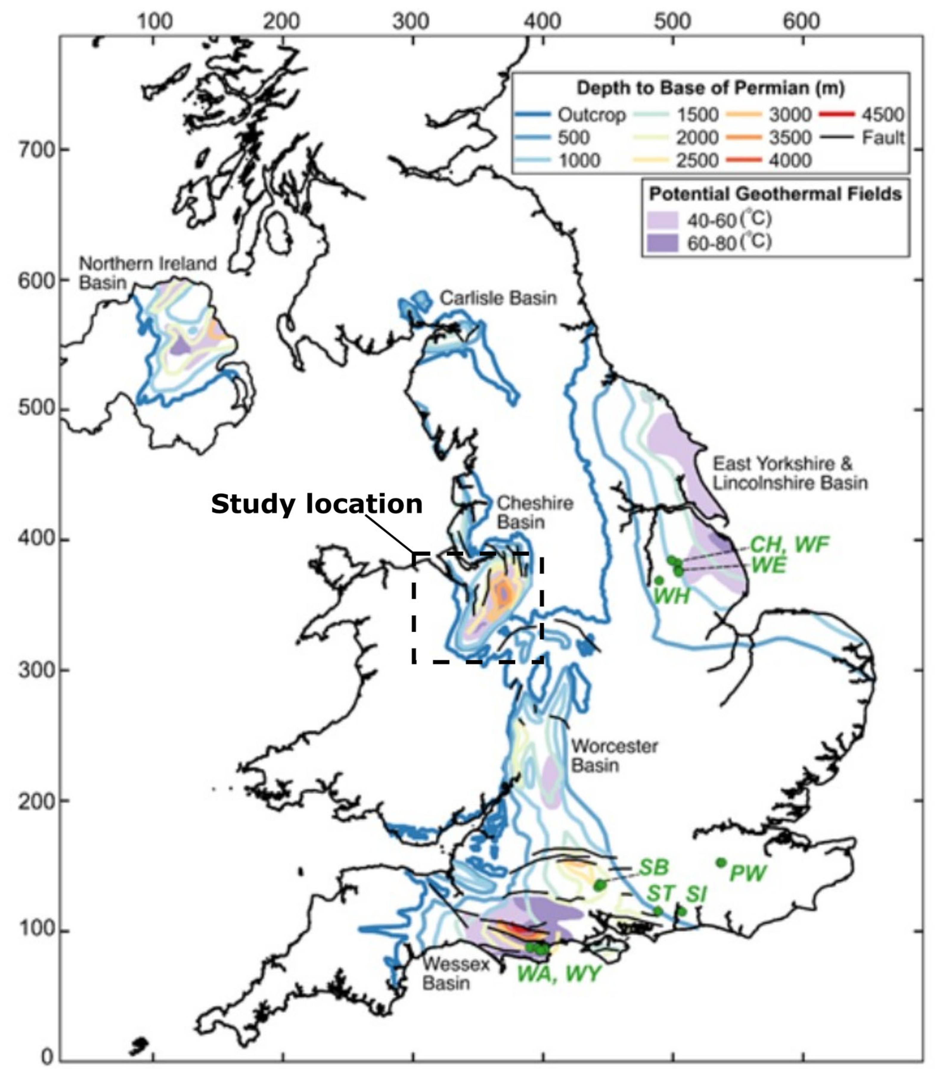
Figure 1. Map of the UK highlighting Permo-Triassic basins and temperature fields. Modified from Watson et al. [5], who digitized the map after Downing and Gray [13]. Note the green dots are associated to oil and gas fields. Grid coordinates are in 100 km intervals for north and east.
Energies 16 01410 g001
Figure 5. (a) Temperature map of the Cheshire Basin using 27 °C/km geothermal gradient. Resolution of 250 m spacing. Derived from South West Pennines Model, Lithoframe 3D model—250K data, 13,160 km2 scale BGS Digital Data under License 2022/067-V2 British Geological Survey © and Database Right UKRI. All rights reserved [58]. (b) Temperature map of the base of Triassic sandstones. Resolution of 3 km spacing. Temperature maps derived from BGS depth maps. Contains British Geological Survey materials Copyright NERC 2022 [59].
Energies 16 01410 g005
Figure 6. Frequency chart for temperature at the base of the basin.
Energies 16 01410 g006
Figure 7. Temperature map of the Cheshire Basin using 20 °C/km geothermal gradient. Resolution of 250 m spacing. Derived from South West Pennines Model, Lithoframe 3D model—250K data, 13,160 km2 scale BGS Digital Data under License 2022/067-V2 British Geological Survey © and Database Right UKRI. All rights reserved [58].
Energies 16 01410 g007
Table 6. Geothermal potential assessment for varying porosity values: 1 EJ = 1 × 10¹⁸ J.
Geothermal Gradient (°C/km)Porosity (%) H i p   ( EJ ) E r   ( EJ ) T P   ( GW th )
206844.24.4
35984.95.2
2761336.67
351567.88.3
Disclaimer/Publisher’s Note: The statements, opinions and data contained in all publications are solely those of the individual author(s) and contributor(s) and not of MDPI and/or the editor(s). MDPI and/or the editor(s) disclaim responsibility for any injury to people or property resulting from any ideas, methods, instructions or products referred to in the content.