Article

Possibility of Marine Low-Speed Engine Piston Ring Wear Prediction during Real Operational Conditions

by
Włodzimierz Kamiński
1,* and
Iwona Michalska-Pożoga
2
1
Faculty of Marine Engineering, Maritime University of Szczecin, 70-500 Szczecin, Poland
2
Department of Mechanical Engineering, Koszalin University of Technology, Raclawicka 15-17, 75-620 Koszalin, Poland
*
Author to whom correspondence should be addressed.
Energies 2023, 16(3), 1433; https://doi.org/10.3390/en16031433
Submission received: 17 October 2022 / Revised: 19 January 2023 / Accepted: 25 January 2023 / Published: 1 February 2023

Abstract

:
A long-stroke, low-speed marine engine is used as the prime mover of a ship. During the operation of such engines, the excessive wear of the cylinder liners and piston rings frequently occurs. The breakdown of cylinder liners or piston rings is very dangerous for the safety of a vessel, the environment, and the people on board. The reliability of engine components is an extremely important topic, as it influences the efficient operation of the vessel. Therefore, to prevent such undesired events, it is essential that the condition of the cylinder liners and piston rings is frequently assessed. This paper presents research that finds prediction models for the rate of piston ring wear. The compiled prediction models are verified using verification tests. The models can be implemented to evaluate the tendency of piston rings to wear, and can be used to evaluate the quality of cylinder liner lubrication. Our findings will help to obtain the required optimal piston ring wear rates, maintain the good operational condition of the engine, reduce the costs of engine maintenance, and reduce the total consumption of lubricating oil and the emission of noxious substances into the atmosphere. All the mentioned benefits are related to a reduction in the ship’s operational costs and are directly related to energy efficiency.

1. Introduction

A marine low-speed engine is used as a ship’s main propulsion, so keeping the engine in a good technical condition is a topic of high importance for owners and operators. During the operation of such engines, the excessive wear of cylinder liners (CLs) and piston rings (PRs), and problems associated with scuffing frequently occur. Statistically, such failures cause the highest proportion of all the recorded marine low-speed engine breakdowns. The failure and malfunction of cylinder liners or piston rings are very dangerous for the safety of vessels, the environment, and the people on board, and they deteriorates the overall performance of the engine [1]. The reliability of an engine’s components is an extremally important subject for ship operators, as it influences the efficient operation of the vessel. Trends in the reduction of cylinder oil feeding rates have been observed, but without a consideration of differences among various engine types and sizes, various types of engine operating conditions, and the service lives of cylinder liners and piston rings, etc. To avoid operational problems with cylinder liner or piston ring failures, it is necessary to frequently conduct assessments of the condition of the cylinder liners and piston rings. The tribology of cylinder liners and piston rings in combustion engines has been studied by researchers for many decades. Research has also been performed specifically on marine low-speed diesel engines. Several attempts to simulate the wear and scuffing behavior by rig testing have been previously presented [2]. A theoretical study of piston ring wear in large two-stroke engines was presented by Rodríguez and co-authors [3]. The modeling of piston rings wea was presented by Yuelan and co-authors; this study presented the results of a simulation of piston ring and cylinder liner motion, performed on an SRV 4 temperature-, friction- and wear-testing machine. They observed that the Cr-plated piston ring and cylinder liner wear process is mainly abrasive. When the load increases, serious abrasive wear and adhesive wear take place, due to the emission of heat in the friction phenomena. When relative motion happens between two materials, adhesive wear takes place by plastic deformation under contact stress at a high load; this transfers from one surface to another surface and forms a transfer film on the grinding surface after continuously reciprocating the friction, scuffing, adhesion and peeling [4]. Figure 1 presents the morphology of the wear scars of Chromium-plated piston rings obtained by Yuelan.
Obviously, during engine operation, the piston ring surface is ideally maintained, as presented in images A and B on Figure 1. For a better understanding of the piston ring wear process, a one-dimensional analysis pf the lubrication between the piston ring and the cylinder wall was developed and presented by Yeau-Ren Jeng [5]. Jeng’s research data were presented for a typical automotive engine. The piston ring was treated as a dynamically loaded bearing with a combined sliding, reciprocating and squeezing motion. A system of two nonlinear differential equations was used to model the lubrication, including the Reynolds cavitation boundary condition. A numerical procedure was developed to calculate the cyclic variations in the film thickness, frictional force, power loss, and oil flow across the ring. The effects of the ring profile, ring tension and engine speed were examined. It was shown that this analysis can be used to study the influence of ring design parameters, in order to improve the design of the ring pack in reciprocating engines. Yeau-Ren Jeng stated that a higher engine speed tends to allow hydrodynamic lubrication, a greater lubrication film thickness and less boundary lubrication. He analyzed the influence of other engine factors, such as the engine’s load, the width of the piston rings, and the height of the piston crown for hydrodynamic lubrication. Golloch and others [6] developed and described two measuring systems for the direct measurement of the friction forces of the piston assembly group, and for the oil film thickness between the top piston ring and the cylinder liner. A better understanding of the tribological processes is necessary in order to reduce the fuel consumption, emissions and wear. The scuffing phenomenon has been a topic of research over the years., According to the ASTM Terminology standard G40, Scuffing is a form of wear occurring in inadequately lubricated tribosystems that is characterized by macroscopically observable changes in texture, with features related to the direction of motion. However, there is still no agreement on the mechanisms of the scuffing phenomenon [7]. The catastrophic nature of scuffing in engine cylinder liners and piston rings means the normal low wear rate increased to a very high rate. Scuffed cylinder liners or piston rings have to be renewed, which typically takes 18–24 h and can cost up to more than USD 100,000. Unplanned stops and expenses are never desirable in the shipping industry, where costs are essential for the competitiveness of a company. When a ship is at sea, the engine power must be fail-safe; therefore, the prevention of scuffing has a safety aspect. In order to fulfill these requirements, marine low-speed engine piston ring wear rates need to be kept in an acceptable range, below 40 [µm/1000 WH] for PR No.1 and 20 [µm/1000 WH] for PR No. 2,3 and 4. [8]. This paper presents the results of a performed series of research tests during the operation of a chosen marine low-speed engine, in order to find the relationship between the wear ratio of piston rings and depending on various operational factors. Research has been conducted in order to find the PR wear prediction model that can be applied during the operation of a marine, low-speed engines. Commercial pressure quite often does not allow the vessel to be stopped in order for maintenance or inspections to be performed on the main engines. In such cases, operators do not know what the actual condition of the piston rings is, unless it is worsening the engine’s performance. For this reason, prediction models of piston ring wear would be very useful [9,10,11]. The implementation of prediction models for marine engines in day-to-day operation could reduce the costs of engine maintenance, reduce the consumption of cylinder lubricating oil and reduce the emission of noxious substances into the environment. It increases the reliability of marine engines and overall improves the management of a ship’s engine department resources. All the mentioned benefits are related to a reduction in a ship’s operational costs and are directly are related to energy efficiency.

2. Research on Marine Low-Speed Engine Piston Ring Wear Ratio

To identify the wear ratios of piston rings, a series of research tests were performed during the operation of three chosen marine slow-speed engines, in order to find the relationship between the wear ratio of piston rings, depending on various operational factors. Research tests were performed on the following objects: three marine low-speed engines, each with 7 cylinders and a power of 27,160 [kW] at 74 [RPM], and installed as prime movers on commercial vessels in normal operation.
The operators of marine low-speed engines have three methods of estimating the piston ring wear ratio in order to make an assessment of the CL–PR assembly lubrication quality.
  • Direct measurements of thickness and height of PR using a standard micrometer [8,12,13]. Obtaining these measurements is only possible during a scheduled or unscheduled piston and liner overhaul. The measurements of piston ring wear performed during overhauls do not give information in relation to the lubrication quality; they are also useless for the prediction of PR wear trends and for calculating when catastrophic wear takes place [14,15,16,17]. During the normal operation of an engine, only the methods mentioned below can be considered as applicable between overhauls; this is on the grounds of their simplicity and the ability to perform these measurements within the short time that the vessel is lying in the port.
  • Measurement of piston rings and cylinder liner assembly radial wear. Clearance c in the piston ring gaps can be achieved in the dead center of the piston bottom, on the condition that they can be reached through the scavenge ports. These measurements are not easy to perform due to the limited space for taking proper gauging. The results of the measurements obtained in this way can be used for calculating the total wear PR–CL (piston rings–cylinder liner assembly), and for evaluating the partial wear as a consequence of operating for a certain number of hours. The radial wear of PR–CL assembly h is determined from the following Equation (1):
h = c ( c 0 + π ( d D ) ) 2 π
where
h—PR–CL wear (radial) [mm];
c—measured PR gap length [mm];
co—initial PR gap length (measured after installation of new piston rings);
d—Cylinder liner diameter measured at the height of the scavenge ports [mm];
D—Cylinder liner diameter (nominal size) [mm].
The cylinder liner diameter, d, used in Equation (1) is the result of its last accessible measurement obtained at the height of the scavenge port, or is the result of measurements taken by the engine’s maker before the instillation of a new cylinder in a newly built engine [18,19,20]. This kind of measurement does not give the answer to what this study aims to measure, i.e., the wear of the piston rings (PR) or the wear of the cylinder liners (CL).
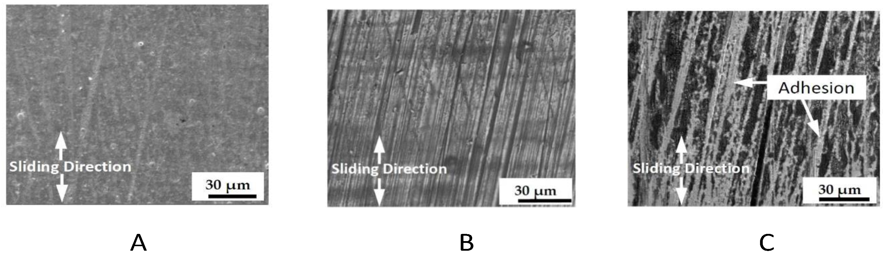
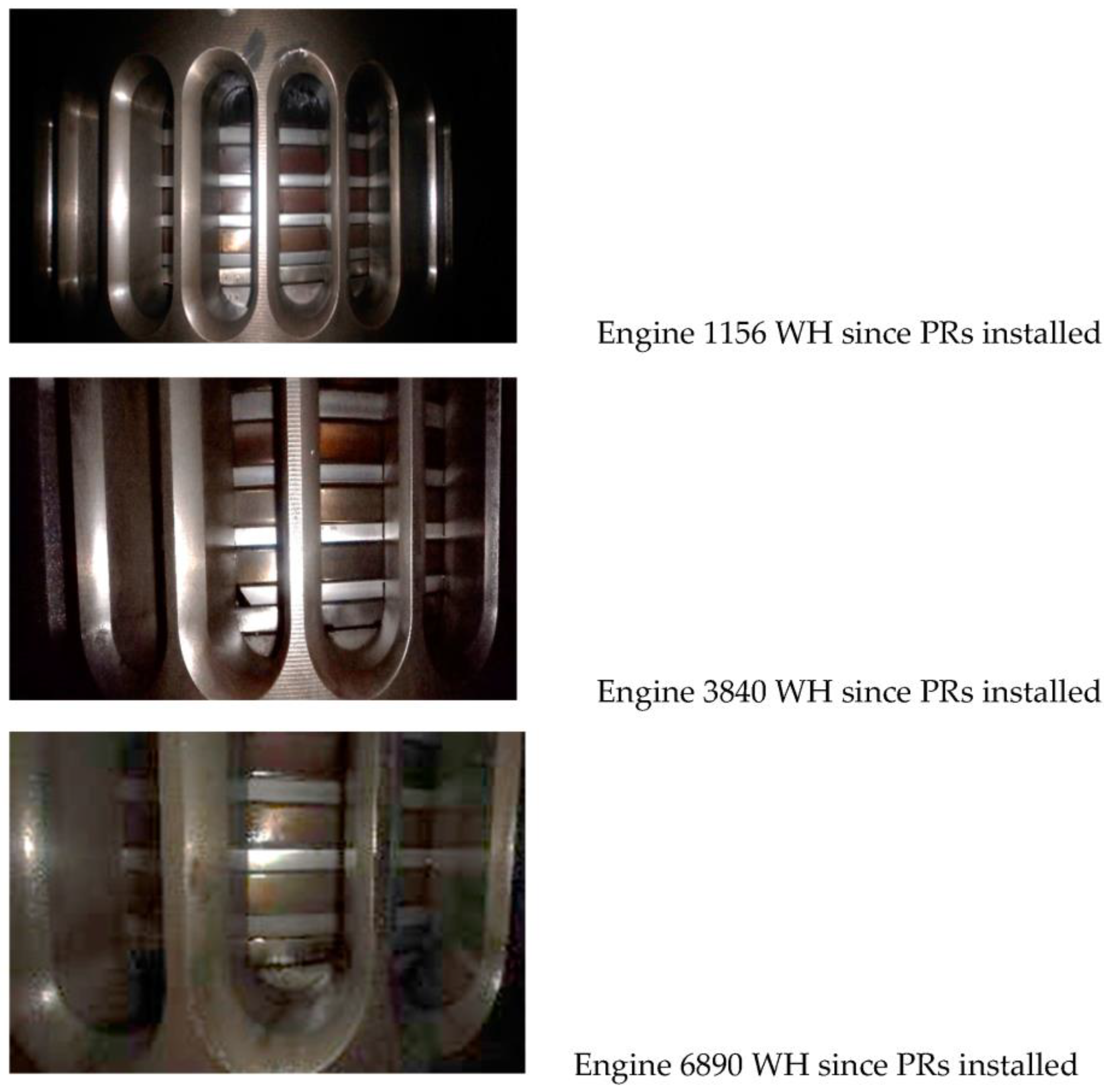
  • Direct measurements of PR wear based on PR’s coating surface thickness measurement. The coating of PRs, usually plasma thermal-sprayed coatings of Mo/NiCr/Cr-C, the purpose of which is to improve the tribological properties and increase the wear resistance of PRs, gets worn out upon engine operation. The PRs’ coating thickness can be measured with lepto-scopes, utilizing electromagnetic (induction) methods for non-ferrous layer measurement. These measurements are usually made via scavenge ports. the thickness measurement results of the PR coating can be used as a function of coating wear, depending on the number of working hours the piston rings have been used. The obtained results can be a reliable argument for evaluating the tendencies of their wear and for estimating their service life until the overhaul time is due, and can finally be used to assess the CL–PR lubrication quality. The total wear of the PRs’ coating gives strong information regarding whether the replacement of the piston rings is necessary, because PR resistance to tribological wear becomes significantly lower [9,21,22].
To perform the planned research task, in order to find prediction models for the wear rates of piston rings, the measurements for a non-ferrous layer of the main engine’s pistons rings’ coating were tested, and visual inspections of the cylinder liners through scavenge spaces were performed. All the tests were performed on three chosen engines, installed as prime movers on ships; they were tested at an engine stand-still condition, after the engine’s operation with a steady load, and during the normal ship’s operating conditions [8,12,13]. This means that the tests were performed after the completion of the running-in process of PR–CLs, in the range of 1500–18,000 WH working hours after an overhaul of the PR–CL assembly. Marine low-speed engine PR–CL assemblies are usually overhauled after 12,000 to 18,000 engine WH (working hours). Recently, the time between CL–PR assembly overhauls is greatly extended, even to 20,000 WH, due to economic reasons. Using an expert’s knowledge, the test engine’s overall technical condition was evaluated as being very good. All the operational parameters, e.g., the temperatures and pressures of the cooling water, lubricating oil and exhaust gases, were kept within the recommended engine maker’s range and were appropriate for the engine condition. Due to the limitation of the presented article, those parameters have not been presented. During the performed research, the thickness of the non-ferrous layer of all the installed piston rings in the three tested engines was measured. Each engine had 7 pistons, as was presented above in this text, and each was equipped with a set of four PRs. In this way, a total of 84 piston rings was tested during the performed research. The thickness of each PR’s non-ferrous layer was tested periodically after each engine’s certain WH, in order to obtain a sufficient number of statistically valid data. The authors were able to measure the non-ferrous layer of each PR five times. Each time, measurements for the thickness of each PR’s non-ferrous layer were taken in four places on the circumference of all the PRs installed on each tested engine. All the taken measurements were repeated at least three times to obtain as much reliable and true data as possible. During the performed research for the identification of wear rates, more than 5000 measurements of the thickness of the non-ferrous layers were taken. Additionally, 1800 measurements of the thickness of the PRs’ non-ferrous layer were taken while performing “verification tests”. The thickness was measured using lepto-scopes. The lepto-scopes used for the measurement of the non-ferrous layer were calibrated each time before the measurements of the engines’ PRs were taken. These measurements were obtained via the engines’ scavenge air ports [23,24]. Figure 2 presents an example of the piston rings’ condition, depending on the engines’ WH since the new PR had been installed. The images were taken by the authors during the performed research tests.
Measurements were taken and calculated for the wear rate at specific engine working hours (WH), at certain average engine loads, engine revolutions per minute (RPM) and cylinder oil feed rates (COFR), during the period between measurements. For the calculation of the wear rate average, the wear rates were calculated for all 7 units of each engine. The average wear rates for PR No.1 and for PR No.2 are presented separately. The average wear rates for PR No.3 and No.4 were calculated and are presented jointly, because the measurements obtained had statistically similar values. The obtained measurement results are shown in Table 1, Table 2 and Table 3. The initial chromium coating of the newly installed piston rings was as follows [8,12,13]:
  • PR No.1-600 [µm]-Top Ring,
  • PR No.2-310 [µm],
  • PR No.3-310 [µm],
  • PR No.4-310 [µm].
Due to the operation of engines with the optimal lubrication of the PR–CL assembly, good results for the piston ring wear rates were obtained. It would be ideal if the anti-wear coating of the PR could last more than 18,000 WH. This corresponds to the period between repairs that is related to the renewal and overhaul of the PR–CL assembly of marine low-speed engines. This is performed every 2.5 years (±3 months), and on engines with an average 15,000 to 18,000 WH. The application of cylinder oil feed rates is on a level that ensures a satisfactory piston ring anti-wear coating that will help avoid unnecessary engines breakdowns and the deterioration of vessels’ commercial performance [25,26].
It was found that, when the piston speed decreases to 6.0 m/s or less (it corresponds to the engine’s 55 RPM), the piston ring wear rates increase significantly. This is visible in Table 1, Table 2 and Table 3, which concern all the piston rings on all the tested engines. Using statistics, this study found that the most essential factors for piston ring coating wear rates are the cylinder oil feed rate, the engine’s load and the engine speed/RPM. The engine RPM and COFR are factors that are available anytime when needed for engines installed on ships. The engine load, which is a more difficult factor to estimate on board vessels, has been omitted; however, the engine load is proportional to the engine’s RPM to a third power in normal operational conditions. All the data gained during the research performed on research test engines No. 1 and No. 2 and No. 3 were used with the aid of the program STATISTICA (license JPZ009K288211FAACD-Q); this was in order to find the piston ring wear rate mathematical prediction models, depending on the engine RPM and COFR. The program STATISTICA was used for regression analysis, in order to find the most accurate prediction model.
Figure 3 presents the obtained results of the average wear rates for the 21 units of PR No.1 in all three engines, depending on the following: engine RPM (piston speed) and set cylinder oil feed rate (COFR).
Figure 4 presents the obtained results of the average wear rates for the 21 units of PR No.2 in all three engines, depending on the following: engine RPM (piston speed) and set cylinder oil feed rate (COFR).
Figure 5 presents the obtained results of the average wear rates for the 21 units of PR No. 3 and 4 in all three engines, depending on the following: engine RPM (piston speed) and set cylinder oil feed rate (COFR).
For Piston Ring No.1, the obtained coating wear rate prediction model:
PR 1 WR = 73.06 0.45   RPM 10.77 COFR
where:
PR1WR—predicted coating wear rate [µm/1000 wh]
COFR—actual cylinder oil feed rate [g/kWh],
RPM—actual engine’s RPM [1/60 s]
Standard Dev = 3.364
Standard Error = 0.868
Χ2P = 0.989
For Piston Ring No.2, the obtained coating wear rate prediction model:
PR 2 WR = 73.88 0.36   RPM 32.7   COFR
where:
PR2WR—predicted coating wear rate [µm/1000 wh]
COFR—actual cylinder oil feed rate [g/kWh],
RPM—actual engine’s RPM [1/60 s]
Standard Deviation = 3.127
Standard Error = 0.807
Χ2P = 1.521
For Piston Rings No. 3 and 4, the obtained coating wear rate prediction model:
PR 34 WR = 21.08 0.32 RPM + 10.79   COFR
where:
PR 3 and 4 WR—predicted coating wear rate [µm/1000 wh]
COFR—actual cylinder oil feed rate [g/kWh],
RPM—actual engine’s RPM [1/60 s]
Standard Dev = 2.836
Standard Error = 0.732
Χ2P = 4.38
The presented prediction models are valid for cylinder oils with a base number (BN) [mg KOH/g] in the range of 40 through 50, 65, 70, up to 100, and with a COFR of 1.7 to a minimum of 0.8 g/kWh. If, during the normal operation of a marine low-speed engine with a certain RPM and COFR, the PR coating wear rates calculated using prediction models are higher than:
40 [µm/1000 WH] for No.1 PR
20 [µm/1000 WH] for PRs No. 2,3 and 4,
the engine operators should seriously consider an increase in the COFR, as this is strongly recommended. This will help to obtain the required optimal PR wear rates. The presented PR wear prediction models should be an aid tool for engine operators to maintain the good operational condition of an engine.

3. Piston Rings Wear Ratio Prediction Models Verification Tests on Engine

To verify the piston ring wear ratio prediction models presented in this paper, a series of tests were performed on a fourth engine installed on a commercial vessel during its normal operation; this was a marine low-speed engine with 8 cylinders and a power of 31,040 [kW] at 76 [RPM]. During research tests, a comparison was made between the real obtained piston ring wear rates and the prediction values obtained by calculation using the prediction models. For the measurement of the PR wear ratios, the same methods were used as those during the identification tests performed on Engines No. 1, 2 and 3.
Table 4, Table 5 and Table 6 present the results of the piston ring wear ratio prediction model verification. The values of the PR wear rates obtained by physical measurements were compared with the values predicted by calculations using the model described in this paper. The obtained results show that, by using prediction models, we can make +/− 5% error with the valuation of the PR wear ratio. This value is acceptable for the normal operation of marine low-speed engines.
In addition to the measurements taken via a visual examination of the engine’s pistons, measurements of the piston rings and cylinder liners were performed using an expert’s knowledge, in order to confirm the condition of the PR–CL assembly directly through the scavenge air ports. This kind of inspection provides useful information about the condition of the PR–CL assembly at a low cost, and can confirm proper lubrication. It should be performed whenever it is possible and must be performed safely [27,28,29,30].

4. Discussion

  • The wear rates of piston rings tend to increase when the piston speed is kept lower during maneuvering or super slow steaming. Particular attention should be paid when engines are operated at piston speeds of 6.0 m/s or less, due to the lower stability of the oil film on the cylinder liner surface. When an engine is operating in such a condition, using expert knowledge and the authors’ experience, the cylinder lubricating oil feed rate can be increased by 20%. The results of an increased COFR on the PR–CL assembly performance and condition can be confirmed by the inspection of the PRs through the scavenge air ports. If necessary, the COFR can be increased again.
  • The presented wear rates prediction models can be utilized, but must be followed by a visual inspection of the piston rings and cylinder liners through scavenge spaces and scavenge ports.
  • The values of the PR wear rates obtained by physical measurements can be compared with the values predicted by calculation, using the model described in this paper. The obtained results shown that, by using prediction models, we can make +/− 5% error with the valuation of the PR wear ratio. This value is acceptable for the normal operation of marine low-speed engines.
  • The predicted PR wear ratios are useful to estimate the time horizon of reaching the limits of wear when catastrophic wear can take place and when the anti-wear coating disappears.
  • Setting up an optimal cylinder oil feed rate should protect the engine against the abnormal wear of the piston rings–cylinder liner assembly, and secure around 15,000–18,000 WH of good engine operation between overhauls of the PR–CL assembly.
  • A specifically adjusted cylinder oil feed rate for each engine can reduce the number of cylinder liner pistons and piston ring failures, can reduce the total cylinder oil consumption and reduce the emission of harmful substances into the atmosphere. It increases the reliability of marine engines and overall improves the management of a ship’s marine power plant resources. All the mentioned benefits are related to a reduction in a ship’s operational costs and are directly are related to energy efficiency.
  • The idea performed and presented in this research paper aimed to find ways to aid operators in the maintenance of PR wear rates within an acceptable range. In the day-to-day operation of engines, innovation is due; this will be used to create PR wear rate prediction models, evaluate the tendencies of their wear, estimate their service life until the overhaul time is due and, finally, to evaluate the CL–PR lubrication quality. However, we would like to point out that the research was conducted in the real operation of engines used for the propulsion of ships. Many of factors measured were not possible to take.

5. Conclusions

  • The presented research was conducted to find user-friendly piston ring wear rate prediction models; this was due to a lack of such aid for operators in the operation of marine low-speed engines in day-to-day operation. This research helps to reduce the costs of engines maintenance, reduce the total cylinder lubricating oil consumption and reduce the emission of noxious substances into the environment. The implementation of these prediction models in marine engines can increase the reliability of marine engines and overall improve the management of ships’ engine department resources.
  • Unplanned stops due to the breaking down of the CL–PR assembly and the expenses that cover such events are never desirable, especially not in the shipping industry, where costs are essential for the competitiveness of shipping company. Preventing the mentioned events also has a safety aspect; when at sea, engine power must be fail-safe. The prediction models of the PR wear rates presented in this paper are only one of the aspects able to keep marine low-speed engines reliable and safe. The obtained results can be a reliable argument for evaluating the tendencies of their wear, for estimating their service life until the overhaul time is due and for evaluating the CL–PR lubrication quality.
  • The total wear of the PRs’ coatings gives strong information that suggests the replacement of piston rings is absolutely necessary. In normal operating conditions, keeping proper, acceptable PR wear rates depends of many factors, such as the following: engine COFR, engine Load, quality of fuel used for engine operation, quality and timely performance of proper maintenance of all engine components etc. One of important factors to maintain PR wear rates on an acceptable level is the education and motivation of marine engine operators.
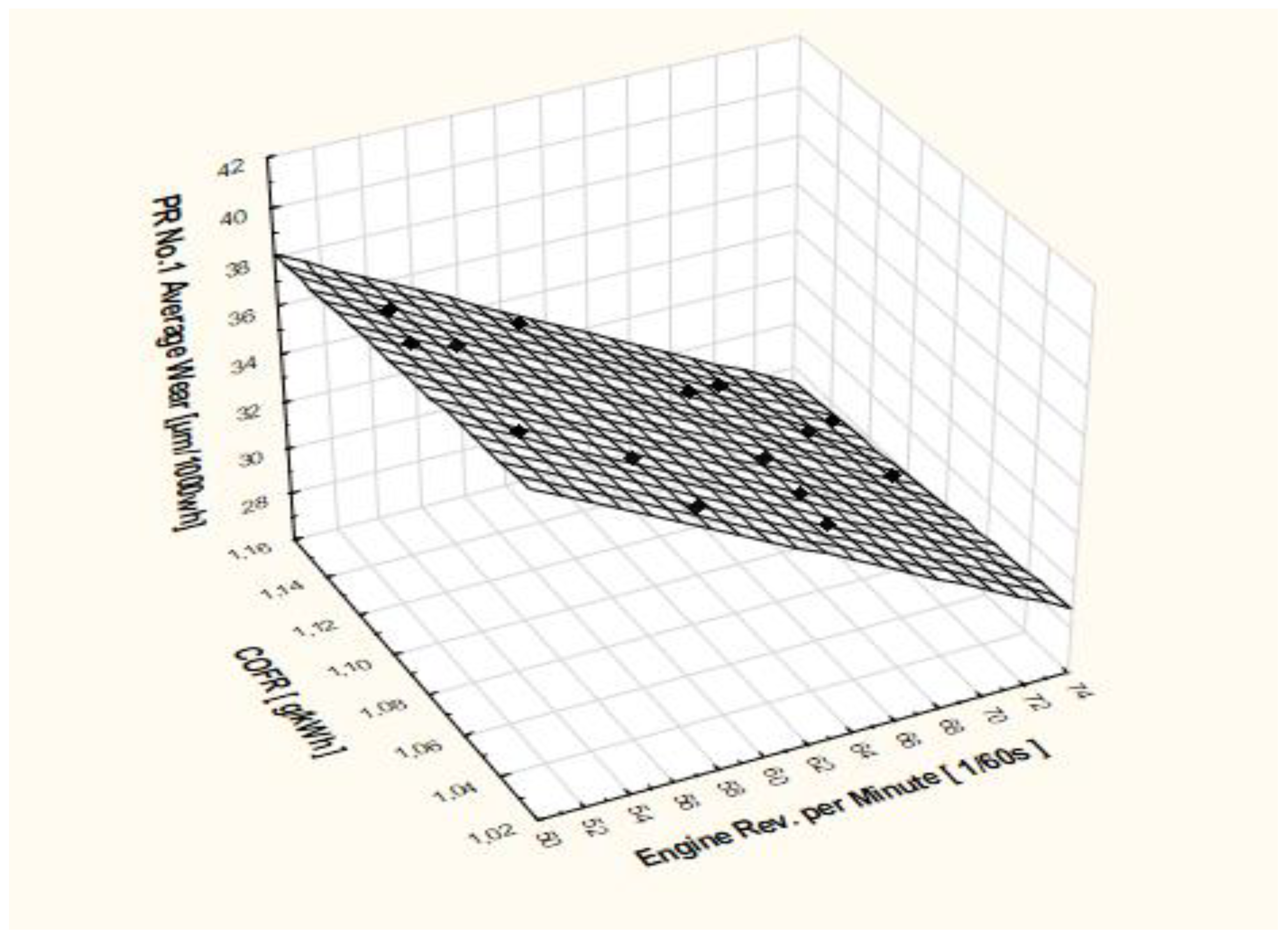
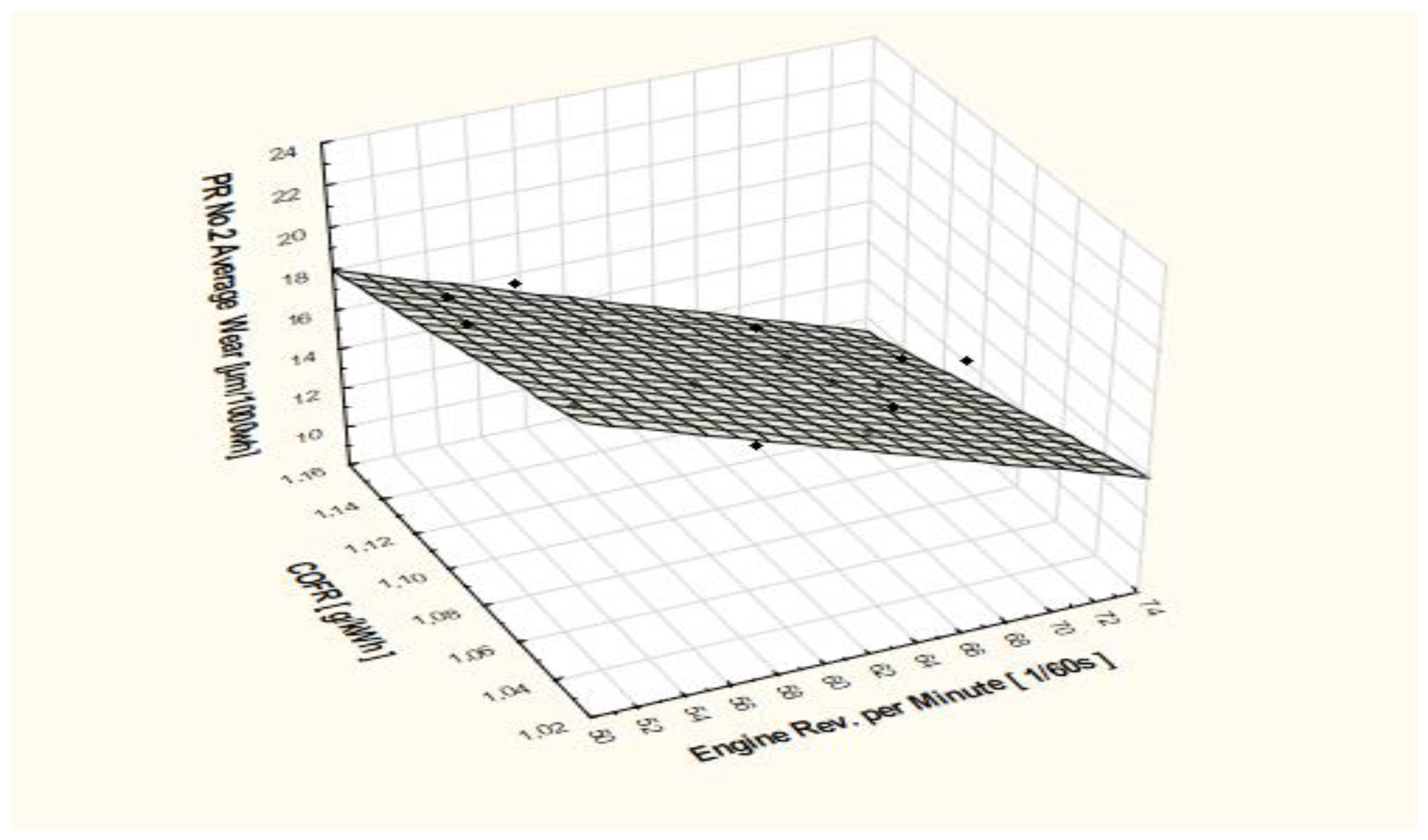
  • If, during the normal operation of a marine low-speed engine, with certain RPM and COFR, the PR coatings wear rate, calculated using prediction models, are higher than: 40 [µm/1000 WH] for No.1 PR and 20 [µm/1000 WH] for PRs No. 2, 3 and 4, it is strongly recommended that engines operators seriously consider an increase in the COFR. It will help to obtain the required optimal PR wear rates.
  • The PR wear rate prediction models presented in this paper are only one of the aspects that make the operation of a marine low-speed engine safe and reliable.

Author Contributions

Methodology, W.K. and I.M.-P.; Formal analysis, W.K. and I.M.-P.; Investigation, W.K. and I.M.-P. All authors have read and agreed to the published version of the manuscript.

Funding

This research performed and presented in the above article was financed with a subsidy from the Polish Ministry of Education and Science.

Data Availability Statement

Not applicable.

Acknowledgments

This research outcome was achieved under a research project for activities of the Koszalin University of Technology.

Conflicts of Interest

The authors declare no conflict of interest. The funders had no role in the design of the study, in the collection, analyses or interpretation of data, in the writing of the manuscript, or in the decision to publish the results.

Abbreviations

PRPiston Rings
CL Cylinder Liner
PR–CL Piston Rings and Cylinder Liner assembly
CLO Cylinder Lubricating Oil
COFR Cylinder Oil Feed Rate [g/kWh]
MCR Engine maximum continuous rate [kW]
PR WRPiston Ring Wear Rate Wear Rate [µm/1000 WH]
BN Base Number of Cylinder Lubricating Oil [mg KOH/g]
RPM Revolutions per minute [1/60 s]
WH Working hours. number of hours in operation [h]

References

  1. Gu, C.; Wang, R.; Tian, T. Modeling the Fatigue Wear of the Cylinder Liner in Internal Combustion Engines during the Break-In Period and Its Impact on Piston Ring Lubrication. Lubricants 2019, 7, 89. [Google Scholar] [CrossRef]
  2. Olander, P.; Hollman, P.; Jacobson, S. Piston ring and cylinder liner wear aggravation caused by transition to greener ship transports–Comparison of samples from test rig and field. Wear 2013, 302, 1345–1350. [Google Scholar] [CrossRef]
  3. Rodríguez, A.L.; Vølund, A.; Klit, P. Modeling of piston ring wear. Proc. Inst. Mech. Eng. Part J J. Eng. Tribol. 2021, 235, 629–638. [Google Scholar] [CrossRef]
  4. Yuelan, D.; Zhihai, C.; Ping, Z. The Tribological Performance of CrMoN/MoS2 Solid Lubrication Coating on a Piston Ring. Lubricants 2017, 5, 13. [Google Scholar] [CrossRef]
  5. Yeng, Y.-R. Theoretical Analysis of Piston-Ring Lubrication Part I—Fully Flooded Lubrication. Tribol. Trans. 1992, 35, 696–706. [Google Scholar] [CrossRef]
  6. Golloch, R.; Kessen, U.; Merker, G.P. Tribological investigations on the piston assembly group of a diesel engine. MTZ Worldw. 2002, 63, 21–24. [Google Scholar] [CrossRef]
  7. Olander, P.; Eskildsen, S.S.; Fogh, J.W.; Hollman, P.; Jacobson, S. Testing scuffing resistance of materials for marine 2-stroke engines—Difficulties with lab scale testing of a complex phenomenon. Wear 2015, 340–341, 9–18. [Google Scholar] [CrossRef]
  8. Operation Data and Maintenance Instruction Manual MC Series Engines Edition 2005. B&W Man. Available online: https://seatracker.ru/viewtopic.php?t=1516 (accessed on 1 August 2021).
  9. Liu, S.; Chen, H.; Shang, B.; Papanikolaou, A. Supporting Predictive Maintenance of a Ship by Analysis of Onboard Measurements. J. Mar. Sci. Eng. 2022, 10, 215. [Google Scholar] [CrossRef]
  10. Kiriakos, A.; Efthimios, G.P.; Zannis, T.C.; Leligou, H.C. Prediction of a Ship’s Operational Parameters Using Artificial Intelligence Techniques. J. Mar. Sci. Eng. 2021, 9, 681. [Google Scholar] [CrossRef]
  11. Koszałka, G. Model of Operational Changes in the Combustion Chamber Tightness of a Diesel Engine. Eksploat. I Niezawodn. Maint. Reliab. 2014, 16, 133–139. Available online: https://www.researchgate.net/publication/295603907 (accessed on 10 July 2022).
  12. Operation Data and Maintenance Instruction Manual MC Series Engines Edition 2010. B&W Man. Available online: https://www.academia.edu/36931905/Instructions_MAN_B_and_W_MC_Engines_OPERATION (accessed on 30 August 2022).
  13. Operation Data and Maintenance Instruction Manual MC Series Engines Edition 2014. B&W Man. Available online: https://www.academia.edu/30054619/MAN_B_and_W_Diesel?sm=b (accessed on 30 July 2022).
  14. Chew, F.; McGeary, T. Analysis of Marine Diesel Engine Cylinder Lubricant Drain as a Means of Monitoring Engine Performance—Editor: MAR-TECH. Singapore September 2000. Available online: https://themartechsummit.com/global-virtual-apac (accessed on 22 June 2022).
  15. Van Doan, D.; Murawski, L. Adjustment of Cylinder Lubricating Oil of Marine Slow-Speed Engines. J. KONES 2017, 24, 113–119. Available online: https://sciendo.com/article/10.5604/01.3001.0010.2803 (accessed on 12 May 2021).
  16. Wajand, J.A.; Wajand, J.T. Tłokowe Silniki Spalinowe Średnio i Szybkoobrotowe; WNT: Warszawa, Poland, 2005; ISBN 83-204-3054-2. [Google Scholar]
  17. Kaminski, W. Analytical assessment of selected engine piston drawing out records and records of feed rates. Sci. J. Marit. Univ. Szczec. 2013, 36, 56–60. [Google Scholar]
  18. McGeary, T.; Chew, F. Paper No.14 Investigation into Abrasiveand Corrosive Wear Mechanisma of Pistons ans Liners in Large Bore 2-Strok Diesel Engine Cylinderse. CIMAC. 2004. Available online: https://www.yumpu.com/en/document/read/39658037/paper-no-14-investigations-into-abrasive-and-flame-marine (accessed on 12 May 2022).
  19. Piotrowski, I.; Witkowski, K. Okrętowe Silniki Spalinowe, 3rd ed.; Trademar: Gdynia, Poland, 2013; ISBN 978-83-62227-48-8. [Google Scholar]
  20. Wlodarski, J.K. Tłokowe Silniki Spalinowe-Procesy Tribologiczne; Wyd. Kom i Łącz.: Warszawa, Poland, 1992; ISBN 8320602884. [Google Scholar]
  21. Chew, F.; McGeary, T. Study of the relationship between cylinder lubricant drain condition and performance parameters of 2-stroke cross-head engines. In Proceedings of the CIMAC Conference on International Council on Combustion Engines, Hamburg, Germany, 7–10 May 2001; paper no. 102. pp. 1–6. [Google Scholar]
  22. Chun, S.M. Simulation of engine life time related with abnormal oil Consumption. Tribol. Int. 2011, 44, 426–436. [Google Scholar] [CrossRef]
  23. Kaminski, W. Assessment and analysis of selected main engines cylinder liners and piston rings wear process. In Proceedings of the 17th International Multidisciplinary Scientific Geo Conference SGEM 2017, Vienna, Austria, 27–29 November 2017; ISBN 978-1-5108-4819-1. [Google Scholar] [CrossRef]
  24. Kaminski, W. Marine Long Stroke Engines Cylinder Liners and Piston Rings wear monitoring using analysis of scavenge drain oil. In Proceedings of the 18th International Multidisciplinary Scientific Geo Conference SGEM 2018, Albena, Bulgaria, 2–8 July 2018. [Google Scholar] [CrossRef]
  25. CIMAC Guidelines for Lubrication of Two-Stroke Crosshead Diesel Engines. 1997. Available online: https://www.cimac.com/recommendation_15 (accessed on 12 August 2021).
  26. Vizentin, G.; Vukelic, G.; Murawski, L.; Recho, N.; Orovic, J. Marine Propulsion System Failures—A Review. J. Mar. Sci. Eng. 2020, 8, 662. [Google Scholar] [CrossRef]
  27. Wang, J.; Zhang, C.; Ma, X.; Wang, Z.; Xu, Y.; Cattley, R. A Multivariate Statistics-Based Approach for Detecting Diesel Engine Faults with Weak Signatures. Energies 2020, 13, 873. [Google Scholar] [CrossRef]
  28. CIMAC WG8 Recommendation 31 The Lubrication of Two-Stroke Crosshead Diesel Engines. 2017. Available online: https://www.cimac.com/cms (accessed on 12 August 2021).
  29. Dziubak, T.; Dziubak, S.D. A Study on the Effect of Inlet Air Pollution on the Engine Component Wear and Operation. Energies 2022, 15, 1182. [Google Scholar] [CrossRef]
  30. Kaminski, W. Marine Long Stroke Engines Piston Rings Wear analysis at real operational conditions. In Proceedings of the 18th International Multidisciplinary Scientific Geo Conference SGEM 2018, Albena, Bulgaria, 2–8 July 2018. [Google Scholar] [CrossRef]
Figure 1. Cr electroplated piston ring friction wear scars under different static loads. (A) Load 50 [N]; (B) Load 290 [N]; (C) Load 400 [N] [4].
Energies 16 01433 g001
Figure 2. Example of piston rings’ condition depending on the engine’s WH since new PRs had been installed.
Energies 16 01433 g002
Figure 3. Results of average wear rates for PR No. 1 in all engine units, depending on COFR and the engine’s RPM (piston speed).
Energies 16 01433 g003
Figure 4. Results of average wear rates for PR No. 2 in all engine units, depending on COFR and the engine’s RPM (piston speed).
Energies 16 01433 g004
Figure 5. Results of average wear rates for PR No. 3 and 4 in all engine units, depending on COFR and the engine’s RPM (piston speed).
Energies 16 01433 g005
Table 1. Research test results obtained during assessment of Engine No. 1 PRs wear rates.
No.Engine WH since New PRs Installed [WH]COFR
[g/kWh]
Average Engine RPM [1/60 s]Average Engine Load
[% MCR]
PR No.1 Average
Wear Rate [µm/1000 WH]
PR No.2
Average
Wear Rate [µm/1000 WH]
PR No.3 and No.4 Average
Wear Rate [µm/1000 WH]
111561.0552383920.214.2
221281.0565.4673216.811.9
338401.1367.7733111.910.6
445201.1355.65235.418.416.8
568901.1372.083289.412.3
Table 2. Research test results obtained during assessment of Engine No. 2 PRs wear rates.
No.Engine WH since New PRs Installed
[WH]
COFR
[g/kWh]
Average Engine RPM
[1/60 s]
Average Engine Load
[% MCR]
PR No.1 Average
Wear Rate [µm/1000 WH]
PR No.2
Average
Wear Rate [µm/1000 WH]
PR No.3 and No.4 Average
Wear Rate [µm/1000 WH]
145891.11688029.312.310.1
262001.1152.13837.818.916.9
377021.0867.07730.512.611.8
483601.0871.38330.215.112.1
594201.15606333.813.513.1
Table 3. Research test results obtained during assessment of Engine No. 3 PRs wear rates.
No.Engine WH since New PRs Installed
[WH]
COFR
[g/kWh]
Average Engine RPM
[1/60 s]
Average Engine Load
[% MCR]
PR No.1 Average
Wear Rate [µm/1000 WH]
PR No.2
Average
Wear Rate [µm/1000 WH]
PR No.3 and No.4 Average
Wear Rate [µm/1000 WH]
183001.12523838.419.417.1
291281.1265.4753214.814.3
310,6251.0969.38232.214.56.7
412,9201.0960.26332.815.814
516,7131.0458.76035.217.515.1
Table 4. Results of the PR wear ratio prediction model verification obtained for PR No.1.
Engine WH since New PRs Installed
[WH]
Average Engine
RPM
[1/60 s]
COFR
[g/kWh]
Average PR No.1 Wear Rate
(Measured–Real)
[µm/1000 WH]
Predicted
PR No.1
Wear Rate
[µm/1000 WH]
ERROR
PR No.1
Real–Predicted
[%]
6023681.1529.130.07−3.3
709559.8136.235.382.3
830352.51.0039.338.671.6
893556.41.235.634.763.3
943862.21.1533.132.681.3
Table 5. Results of the PR wear ratio prediction model verification obtained for PR No.2.
Engine WH since New PRs Installed
[WH]
Average Engine
RPM
[1/60 s]
COFR
[g/kWh]
Average PR No.2 Wear Rate
(Measured–Real)
[µm/1000 WH]
Predicted
PR No.2
Wear Rate
[µm/1000 WH]
ERROR
PR No.1
Real–Predicted
[%]
6023681.1512.311.784.2
709559.8118.719.64−5.0
830352.51.0022.622.271.5
893556.41.215.014.324.7
943862.21.1513.313.87−4.1
Table 6. Results of the PR wear ratio prediction model verification obtained for PR No.3 and 4.
Engine WH since New PR Installed
[WH]
Average Engine
RPM
[1/60 s]
COFR
[g/kWh]
Average
PR No. 3 and 4
Wear Rate
(Measured–Real)
[µm/1000 WH]
Predicted
PR No.3 and 4
Wear Rate
[µm/1000 WH]
ERROR
PR No.3 and 4
Real–Predicted
[%]
6023681.1511.211.73−4.5
709559.8112.312.73−3.5
830352.51.0015.515.072.8
893556.41.215.215.98−4.8
943862.21.1513.413.58−1.4
Disclaimer/Publisher’s Note: The statements, opinions and data contained in all publications are solely those of the individual author(s) and contributor(s) and not of MDPI and/or the editor(s). MDPI and/or the editor(s) disclaim responsibility for any injury to people or property resulting from any ideas, methods, instructions or products referred to in the content.

