Article

Performance of a Heat-Pipe Cooled Concentrated Photovoltaic/Thermoelectric Hybrid System

by
Mohamed Sabry
1,* and
Abdelrahman Lashin
1,2
1
Physics Department, College of Applied Science, Umm Al Qura University, Makkah 21955, Saudi Arabia
2
Physics Department, Faculty of Science, Mansoura University, Mansoura 35516, Egypt
*
Author to whom correspondence should be addressed.
Energies 2023, 16(3), 1438; https://doi.org/10.3390/en16031438
Submission received: 28 December 2022 / Revised: 27 January 2023 / Accepted: 30 January 2023 / Published: 1 February 2023

Abstract

:
Compared to traditional one-sun solar cells, multijunction concentrator cells operating under concentrated solar radiation are advantageous because of their high output and low cooling costs. Such a concentrator PV requires a cooling technique to maintain its performance and efficiency. The performance of a multi-junction concentrator photovoltaic cell of efficiency around 33%, operating under concentrated solar radiation (160–250 sun), has been tested. Heat pipes were used in this study as a fast and efficient way of rejecting heat accumulated in the cells. In this work, the evaporator side of the heat pipe was set in thermal contact with the back side of the solar cell such that the excess heat was transferred efficiently to the other side (condenser side). To positively utilize such excessive heat, two thermoelectric generators were thermally attached to either side of the condenser of the heat pipe, and each was attached to a fin-shaped heat sink. Four different cooling configurations were tested and compared. The net power obtained by this concentrator solar cell employing two types of TEG with different lengths as a cooling alongside two thermoelectric generators for heat-to-electricity conversion was 20% and 17%, corresponding to the long and short heat pipe configurations, respectively, compared to traditional a heat sink only configured at an optical concentration of 230 suns.

1. Introduction

Besides being a green source of renewable energy cells photovoltaics (PV) have proven their performance, reliability, and durability [1]. PV power generation has marked a 22% growth in 2020 [2,3]. It has been accounted as the third largest renewable electricity resource behind hydropower and wind for 3.6% of global electricity generation [2,3]. In recent years, the PV industry grown immensely due to the increased interest in green energy as well as the operating cost reduction [4,5]. For a further reduction in its operating costs, it could run under concentrated solar radiation. Concentrator photovoltaics (CPV) are exposed to high levels of solar radiation intensity, hence their generated current is high, as CPV current is linearly proportional to the incident solar radiation intensity. Besides the traditional (one-sun) systems, two main categories of solar concentrators currently exist in the PV market, namely low concentration systems (concentration ratio up to 10X) that use troughs or parabolic mirrors; and high concentrator systems (may reach 500X or more) that use Fresnel Lenses. Low concentrator systems may require no cooling systems, as they can be ventilated by natural convection, adding zero cost to the total system costs. Unfortunately, operating under high solar radiation intensity elevates the CPV operating temperature, which in turn greatly reduces its generated voltage, resulting in reducing its output power and, hence, efficiency [6].
To maintain its efficiency, CPV operating temperature needs to be reduced by employing any cooling static or dynamic subsystem, depending on the optical concentration ratio used in the system [7]. Active cooling system require pumping a cooling liquid (normally water) to get a forced flow inside the CPV system, resulting in a very good enhancement of the CPV generated power. On the other hand, many problems normally appear like the system leakage, and the added costs of the consumed pumping power and maintenance. In contrary, static cooling although is not as efficient as dynamic, reduces many associated technical problems in addition to the high operating and maintenance costs [8]. Solutions such as surface antireflective [9,10,11] or selective coatings are performed. Others tested the effect of using nanofluids with different shapes of the collectors on the performance of Photovoltaic/Thermal systems [12,13,14].
Several attempts have been performed to achieve an efficient passive cooling technique. Traditional cooling fins allow air to flow under the CPV so that the heat accumulated on its back side dissipates into the surroundings by convection and radiation [15]. A thermoelectric generator has proven applicability for passively cooling the CPV cells as well as the ability to utilize the excess heat accumulated on the CPV by converting it into power that is added to that produced by the main CPV system [16,17].
Heat pipes coupled with thermoelectric generators could be involved in the GaInP/GaAs/Ge multijunction CPV passive cooling process and harvesting additional electrical energy as will be explained shortly.
This practical solution offers a good technique for passive cooling for CPV operating under moderate solar radiation concentration ratios. This proposed technique offers a cooling method that requires no maintenance and no added operating costs, and it adds additional electric power to the CPV traditional heat-fin cooling. For one-sun solar cells, this might not be efficient because the solar cells’ efficiency is low (around 12%); furthermore, no significant thermal energy will be harvested (as it works only under one-sun or less), which makes the TEG of no use.

1.1. GaInP/GaAs/Ge Multijunction CPV Cells

A multi junction PV cell is made with different layers of semiconductors to absorb sunlight and convert it into electricity. These layers have different bandgaps such that each junction absorbs a different portion of the solar spectrum, which widen the absorbed spectral bands, hence increase the generated current. Such cells have high efficiencies under concentrated solar radiation (up to 37% under 500 suns illumination level) provided that their operating temperatures are around 100–120 °C, after which they decay [18,19]. Multi-junction CPV I-V characteristics could be mathematically described by the one-diode model written in (1) [20,21]:
I = I L I 0 · [ e q ( V + I R s ) n k T 1 ] V + I R s R s h ,
where IL: photo-generated current, I0: reverse saturation current, T: absolute temperature, q: elementary charge, k: Boltzmann’s constant, n: diode ideality factor, and Rs, Rsh: series and shunt resistances of the solar cell, respectively.
CPV parameters, hence performance, are very sensitive to the cell’s operating light intensity and temperature. Whereas current is linearly related to the concentrated light intensity, as more photons produce electron-hole pairs, resulting in an increase in the CPV generated short circuit current, voltage increases logarithmically with such light intensity increase. This results in an overall increase in the CPV output power with increasing the optical concentration ratio. On the other hand, as the cell’s temperature increases, its bandgap reduces and broadens, and this affects the cell parameters accordingly. While the cell’s short circuit current shows a slight linear increase with the operating temperature, open-circuit voltage shows a large reduction with increasing such operating temperature.
Open circuit voltage as a function of cell operating temperature is expressed in (2) [22]:
V o c T 1 T [ n q · E g V o c + n k T q · ( 3 + γ 2 ) ] + n k T q · 1 J s c · J s c T + n q · E g T ,
where Eg: absorber bandgap, Jsc: short circuit current density, J s c / T : short circuit current density variation with temperature, and E g / T : the bandgap’s variation with temperature.
The efficiency of a solar cell (η), that is the portion of energy in the form of sunlight that can be converted via photovoltaics into electricity, is a result of the temperature-affected cell parameters expressed as in (3) [23,24]:
η = J s c · V o c · F F P i n ,
where FF: fill factor, and Pin: input power.
The CPV cell on hand is a GaInP/GaAs/Ge 3-junction solar cell (C1MJ) manufactured by Spectrolab [8,25] and has a temperature coefficient of −4.3 mV/°C and −0.06%/°C corresponding to open-circuit voltage and efficiency, respectively, as reported by the manufacturer [26].

1.2. Heat Pipes

The heat pipe (HP) shown in Figure 1 is a device allowing an efficient and fast extraction and transmission of heat. It is composed of a closed, evacuated tube whose outer surface is solid while the subsequent layer is composed of porous metal (wick). The pores in the inner part of the heat pipe are partially filled with a working fluid, which transfers heat via changing its phase between liquid and vapor repeatedly [27,28].The hot object to be cooled is brought in thermal contact with one end of the tube (the evaporator), while the other end of the tube (the condenser) is connected to a heat sink or fins to dissipate heat. The tube body between the evaporator and the condenser is called the adiabatic section since no thermal exchanges occur in this area [29].
In the heat pipes, heat is absorbed in the evaporator section, in which liquid in the wick layer is, as a result, converted into the vapor phase. The vapor flows towards the cold condenser section at the other end due to the pressure difference between the two ends, in which it dissipates the heat and condenses to the liquid phase before moving back to the evaporator section inside the wick layer. This two-phase circulation continues as long as the temperature gradient between the evaporator and condenser is maintained. [30].
The maximum heat that a heat pipe can transfer is both temperature dependent (e.g., through the temperature dependence of the Rynolds number) and temperature differential dependent (a heat pipe with both ends at the same temperature transports no heat). This is expressed mathematically as in (4) [31,32]:
Q ˙ c a p , m a x = 2 σ cos θ e e f f ρ l g L sin γ L e f f ( μ l A w ϕ ρ l H f , g K + 2 ( f R e ) h , ν μ ν D h , ν 2 A ν ρ ν H f g ) ,
where σ: surface tension of the working liquid, eeff: effective pore radius of the wick, θ: mesh wall—working liquid contact angle, g: gravitational constant, L: heat pipe length, γ: heat pipe’s inclination angle, ϕ : porosity of the wick, (fRe)h,v: Reynolds-based friction factor, Aν: vapor space cross-sectional area, μl: viscosity of the liquid, μv: viscosity of the vapor, Leff: effective length, K: permeability of the wick, Aw: wick cross-sectional area, ρl: density of the liquid, ρv: density of the vapor, Hf,g: latent heat of vaporization of the working fluid; and Dh,ν: the vapor hydraulic diameter.
As the temperature differential increases (due to rising cell temperature) the cell efficiency decreases, and the heat transport increases, and therefore the thermal-voltaic device at the end of the heat pipe starts producing energy.
The temperature drop across the two sides of the heat pipe is due to different heat transfer processes: (i) conductive transfer through the outer copper envelope wall and the wick material inside the envelope; (ii) evaporation of the operating liquid in the hot side of the pipe; (iii) temperature drop of the vapor space, which is relatively small; (iv) condensation of the operating liquid in the other side of the pipe, and finally (v) conductive transfer through the envelope wick and the outer wall.
Such heat pipes have many limitations that constrains their operation. Among these limitations are (i) capillarity, or hydrodynamic limitation, which is the insufficiency of liquid to be evaporated and transmitted to the condenser section, that occurs when the maximum capillary pressure is exceeded; (ii) sonic limit, which occurs when the vapor velocity increases inside the pipe and reach its maximum due to the high heating rate.; (iii) boiling of the liquid in the evaporator resulting in dryness of the wick surface.

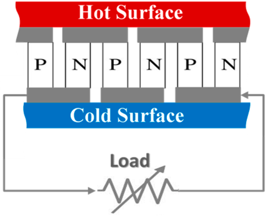
1.3. Thermoelectric Generators

Based on the Seebeck effect, thermoelectric generators (TEG) can convert thermal energy into electricity. Although they have low efficiencies compared to PV, such devices are characterized by being simple, maintenance-free, quiet, and environmentally friendly. TEG devices, being solid-state, are superior by their enhanced reliability, direct energy transformation, silently operated with minimal size. On the other hand, such devices notably have low thermal efficiencies, and it gets even worse when exposed to uneven temperature distribution on their sides.
TEGs are composed of many P-N junction pairs that have an opposite Seebeck coefficient as shown schematically in Figure 2. Such junctions (thermocouples) are made of high performance p- and n-type semiconductor material. It generates electric potential difference across its terminals when there is a temperature difference across the two terminals of each junction. Such potential difference causes current to circulate in the closed external load. TEG output power can be increased by increasing the temperature difference in between hot and cold sides and/or by form a series connection with many thermoelectric power generators.
Due to the Seebeck effect, the temperature difference ∆T between the hot and cold sides of the TEG will generate an output voltage expressed by (5) [33,34]:
V o u t = N ( α A α B ) Δ T
where N is the number of connected thermocouples and α A ,   α B are the Seebeck coefficients of the two joined materials A and B forming the thermocouple. The TEG output power is given by (6) [35,36]:
P = V o u t 2 R L ( R T E G + R L ) 2
where RL and RTEG are the external load and the TEG internal resistances, respectively.
To maximize power output, the denominator has to be minimized by choosing the load resistance equal to that of the TEG; the maximum output power is expressed as (7) [37]:
P = V o u t 2 4 R T E G
In this work, heat accumulated on the back of the CPV is rejected by using a heat pipe element. Moreover, additional electrical energy could be harvested from such rejected heat by employing two thermoelectric generator elements connected in series.

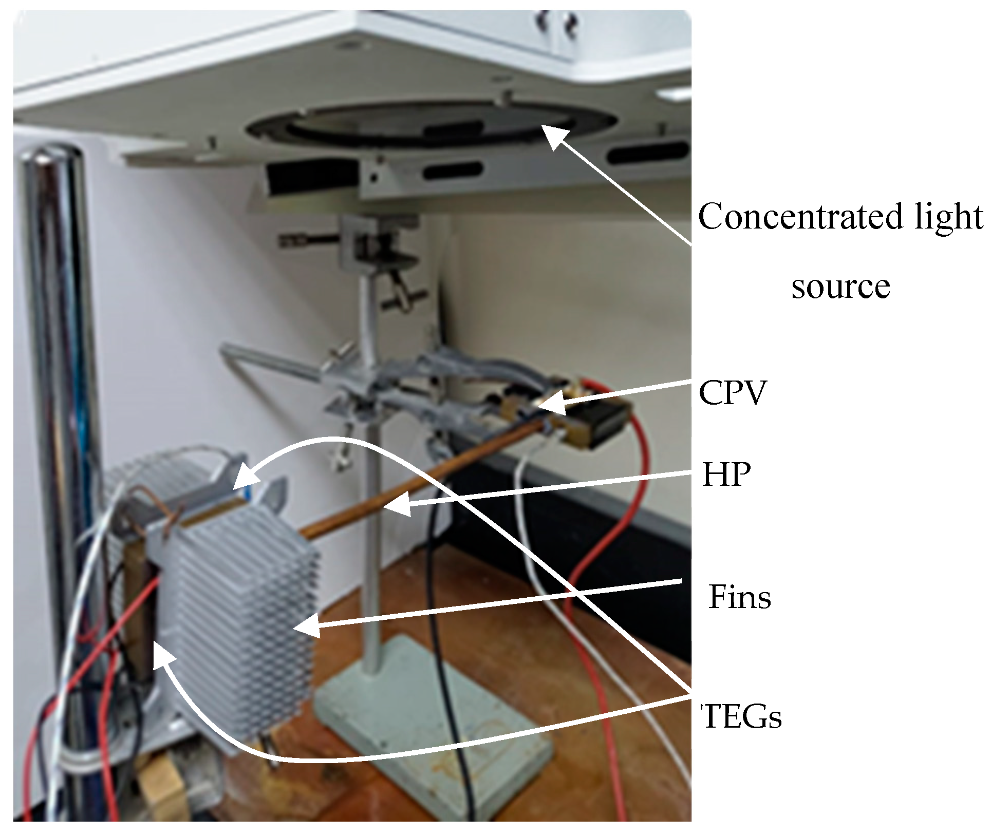
2. The Experimental Setup

The experimental setup used in this work is shown in Figure 3. A GaInP/GalnAs/Ge triple-junction CPV cell was set on top of a copper block, while the evaporator part of the HP was fitted in a hole through this block underneath the CPV. The other side of the HP (the condenser) was fitted in a similar copper block. The hot sides of two TEGs were thermally attached to either side of the latter copper block, and two heat fins were thermally attached to the outer (cold) surface of the TEGs. Thermal grease was used between the different parts in contact like: between the CPV and the copper block, between the TEGs hot sides and the second copper block, and the TEGs cold side and the aluminum heat fins.
The concentrated light source as shown in Figure 3 is a Xenon collimated source, whose specifications (spatial Uniformity, collimation Half Angle, temporal instability, spectral match, and lamp type) are listed in Table 1.
CPV cell parameters (Voc, Isc, Im, and Vm) are extracted from the I-V characteristics, which were measured using a Keithley current source. Thermoelectric current and voltage were measured using digital multimeters. Temperatures were measured using K-type thermocouples.
When the CPV is illuminated by a light source with moderately high optical concentration ratios (150 sun–260 suns), heat accumulated on the back side of the CPV is dissipated to the copper block and hence to the HP, which in turn rapidly and efficiently transfers it to the other side. At the condenser side of the HP, heat will transfer to the TEG’s hot sides, while their cold sides are cooled by the heat fins. This produces a temperature difference between the two sides of each TEG, which in turn generates thermoelectric power that is added to the power generated by the CPV.
This experimental arrangement enables one to increase the CPV cell efficiently and utilizes harmful heat accumulated on the CPV by converting it to electrical power by using TEG elements. This is achieved by:
i.
Employing a heat pipe for a passive (no additional cost for cooling pumps or motors, etc.), fast, and efficient removal of heat accumulated on the CPV, which increases its efficiency.
ii.
Utilizing such heat to generate electrical power by means of thermoelectric generators. This power is added to the total system power.
The description and dimensions of the different parts used in the experiment are tabulated in Table 1.
The performance of the proposed system has been tested in four configurations:
i.
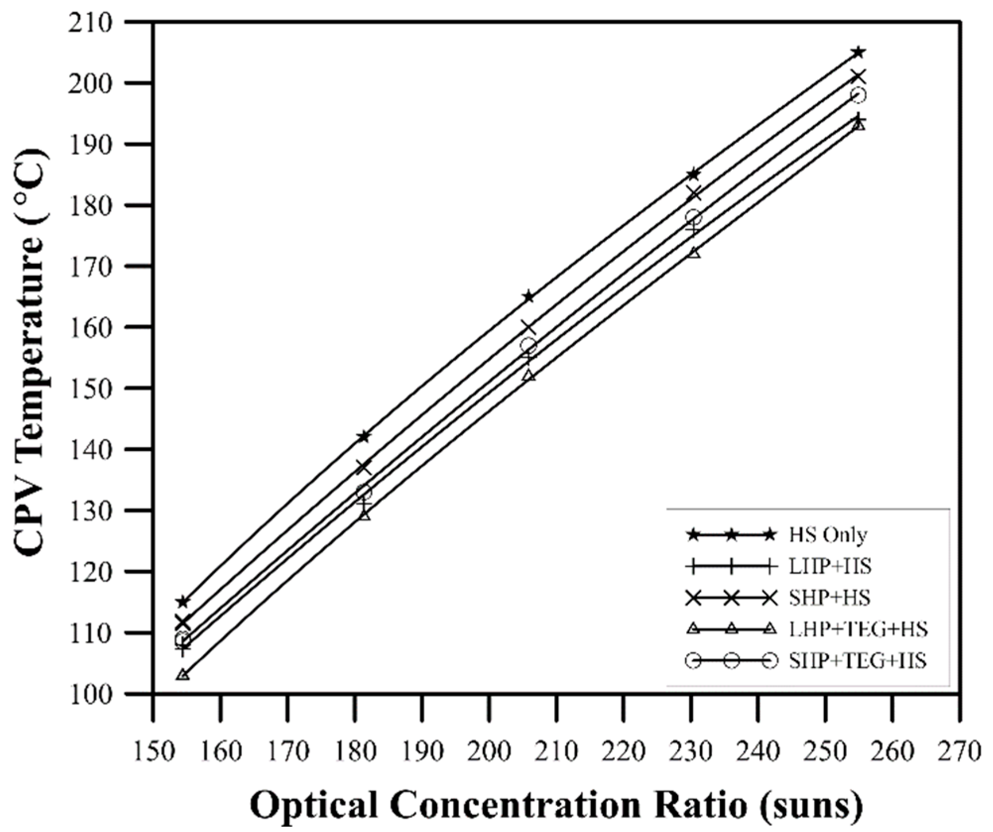
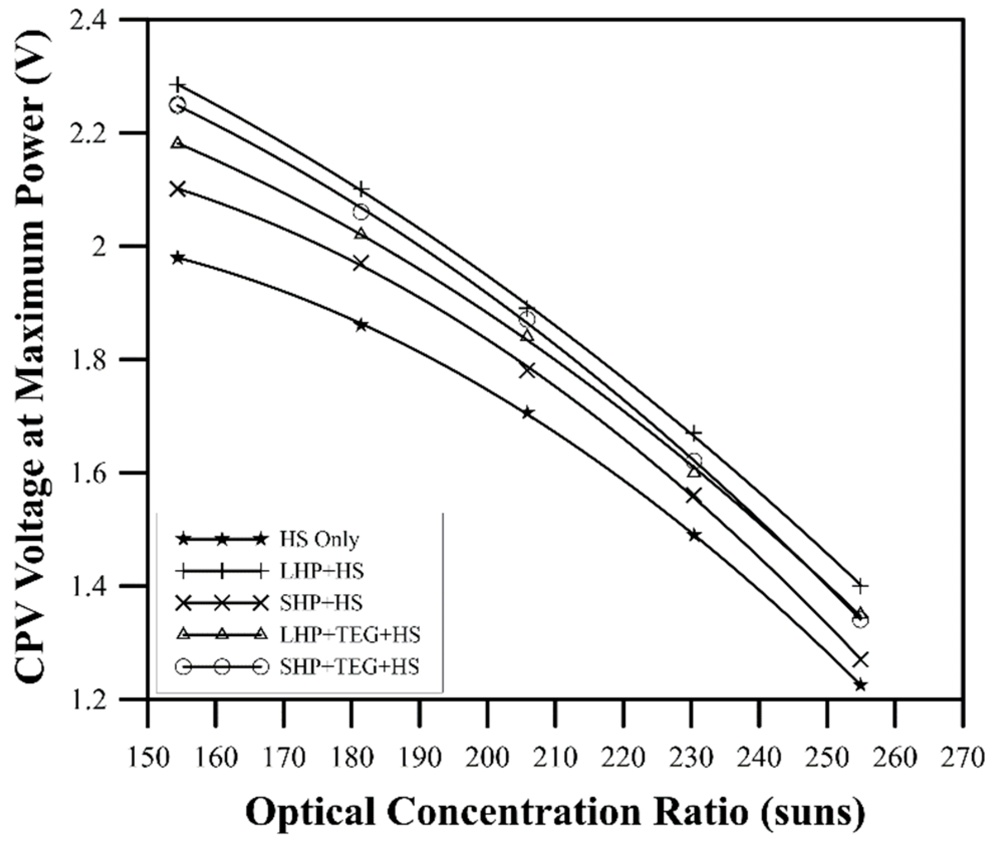
LHP+HS: in which the CPV is connected to a long HP (25 cm) and the fins heat sinks are thermally attached directly on either sides of the second copper block. No TEGs are involved in this configuration and the CPV is the only source of electric power.
ii.
SHP+HS: in which the CPV is connected to a short HP (15 cm) and the fins heat sinks are thermally attached directly on either sides of the second copper block. No TEGs are involved in this configuration and the CPV is the only source of electric power.
iii.
LHP+TEG+HS: in which CPV is connected to a long HP. The second copper block is coupled with two TEGs attached to fins heat sinks. Total generated power is the CPV power in addition to the TEG power.
iv.
SHP+TEG+HS: in which CPV is connected to a short HP. The second copper block is coupled with two TEGs attached to fins heat sinks. Total generated power is the CPV power in addition to the TEG power.
The output of each of the four configurations mentioned above is compared to that of a traditional configuration in which the CPV is connected directly to a one fin heat sink (HS Only configuration).

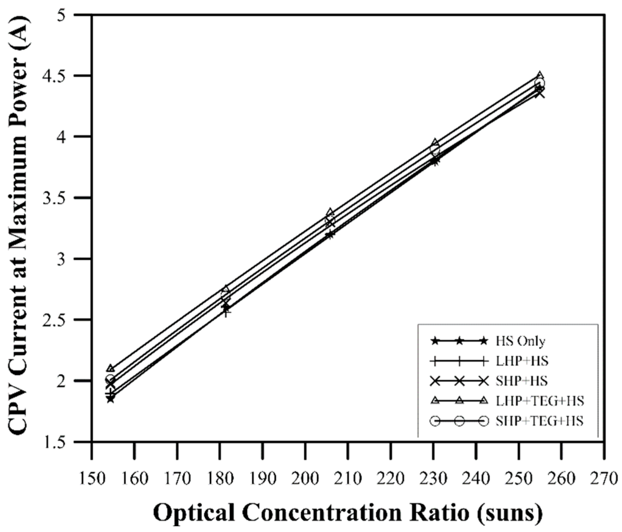
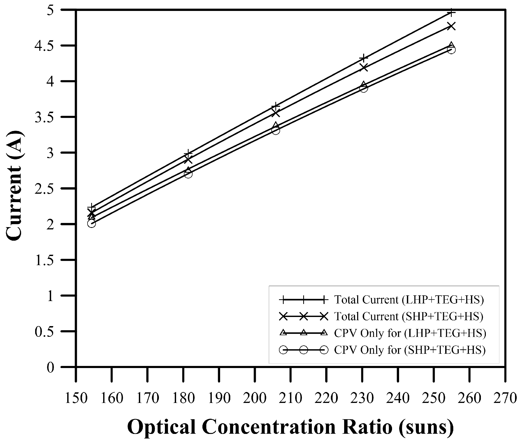
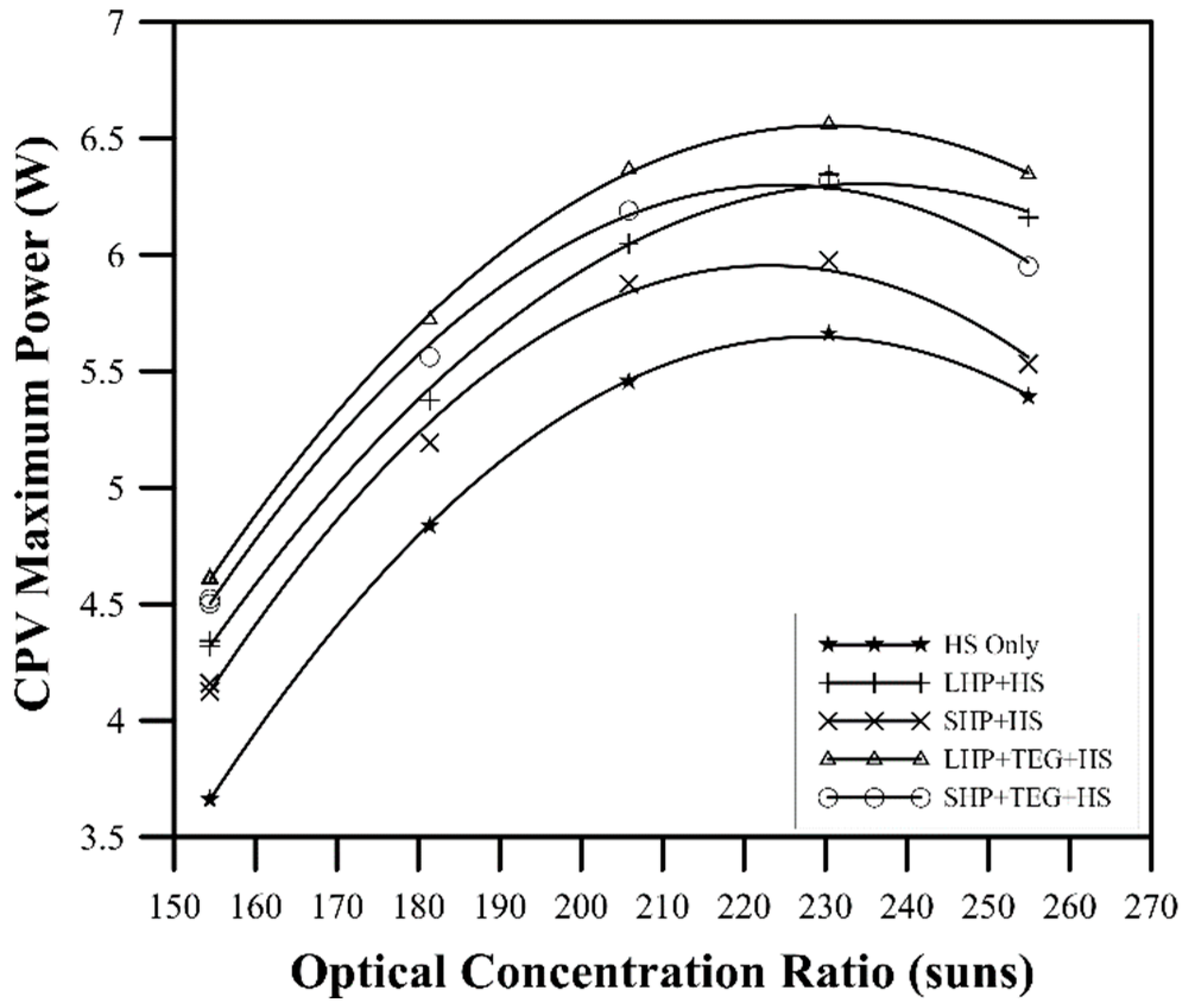
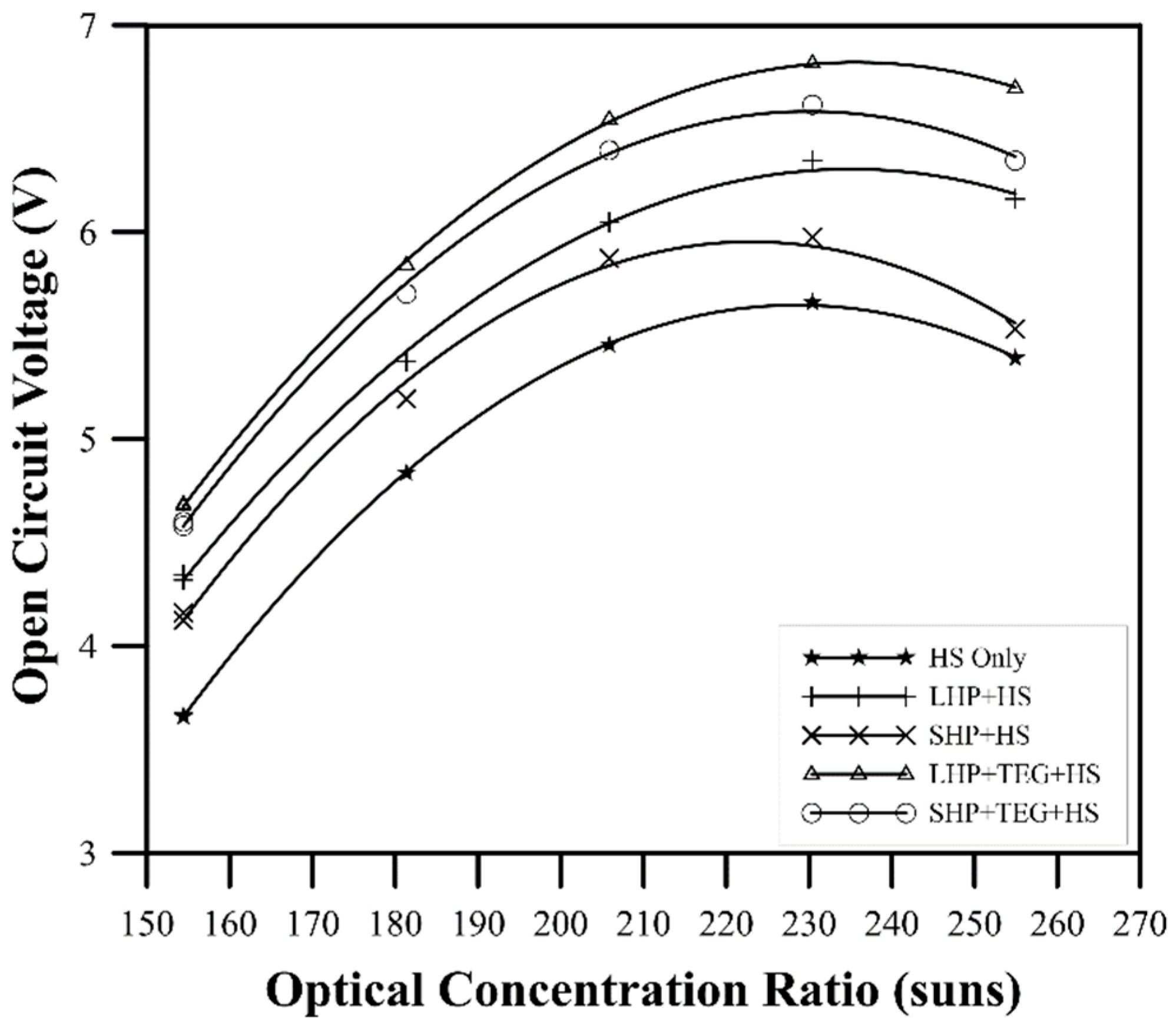
3. Results and Discussion

Figure 4 shows the CPV temperature of the four configurations under the test as well as the traditional configuration (HS Only) as a function of the optical concentration ratio. The HS-only traditional configuration has the highest temperature, which indicates that it is not ideal for CPV passive cooling at this range of optical concentration. The SHP+HS and the SHP+TEG+HS configurations come next, then the LHP+HS, and the LHP+TEG+HS show the lowest CPV temperatures.
Consistent with the CPV temperatures, Figure 5 shows the CPV reduction of voltage at maximum power, caused by temperature elevation due to increasing the optical concentration ratio for the four proposed configurations compared to that of the traditional fins-cooled system. The difference between the voltage values is high for low-input light and decreases with increasing incident light. It is worth mentioning that although the CPV temperature of the LHP+TEG+HS shows minimum values amongst all the investigated configurations shown in Figure 4, this does not reflect (as expected to me maximum) in the measurements of the CPV voltage at maximum power shown in Figure 5. The reason is that the voltage at maximum power, i.e., Vm, is calculated on the I-V curve at the point where the products of I and V are maximum. This point is controlled by the values of both I (which is increasing with temperature and radiation intensity) and V (which is decreasing with temperature and increasing with radiation intensity). The two contradicted effects of the temperature control are the location of the voltage and current at maximum power.
Contrary to the voltage reduction, the CPV-generated current at maximum power illustrated in Figure 6 shows a linear increase of the current at maximum power as a function of the optical concentration ratio for all the configurations under investigation.
Figure 7 depicts the significance of the thermoelectric current to the total system current (CPV current+ TEG current) for the system employing long and short HP.
The inclusive effect of the operating temperature increase is the variation of the CPV maximum power generated as shown in Figure 8. Among all the configurations under investigation, the LHP+TEG+HS configuration shows the highest generated power. The maximum achieved power generated is around the optical concentration ratio of 230 suns, with an increase of about 16% compared to the HS Only traditional configuration. It is clear also that the performance of long HP is better than that of the short.
The figure also shows that the TEG has a very positive effect on the dissipation of the heat accumulated on the CPV. Both configurations with the TEG elements (the LHP+TEG+HS, and the SHP+TEG+HS) show better cooling than those with HP only. At 230 sun, the TEG elements increase the LHP+TEG+HS and SHP+TEG+HS configurations’ output power by about 3.5% and 6% compared to the LHP+HS and the SHP+HS, respectively.
Temperatures of the TEG hot sides for the two configurations having TEG elements as a function of the optical concentration are shown in Figure 9. The configuration having short HP shows a higher temperature at the TEG side (HP condenser side). This indicates that the long HP dissipates heat more efficiently than the short one. This is probably because of the length of the HP body, which allows for higher convective and radiative heat losses around the bigger total surface area of the copper tube. This is reflected in the electrical power generated by the TEGs of the two configurations shown in Figure 10. The SHP+TEG+HS configuration has about 16% more generated electrical power compared to the LHP+TEG+HS configuration.
The overall power (CPV power + TEG power) generated by all the configurations under test is shown in Figure 11. Configurations containing TEGs show higher total power than those without.
At an optical concentration of 230 suns, the total power gains are 20%, 17%, 12%, and 6% for LHP+TEG+HS, SHP+TEG+HS, LHP+HS, and SHP+HS, respectively, compared to traditional HS-only configuration.

4. Conclusions

CPV cells are beneficial compared to one-sun cells for their high output and low costs, provided the existence of an economic and efficient cooling technique. The performance of a multi-junction concentrator photovoltaic cell of efficiency around 33%, operating under concentrated solar radiation (160–250 sun), has been tested against a passive cooling system comprising heat pipes, thermoelectric generators, and fin-shaped heat sinks have been employed in this work.
Heat pipes were used in this study as a fast and efficient way of rejecting heat accumulated on the cells. In addition to the CPV cooling, such excessive heat has been positively utilized with two thermoelectric generators attached to the heat pipe. Four different cooling configurations have been tested and compared.
The CPV back is in thermal contact with one end of the HP (the evaporator), while the other end (the condenser) is in thermal contact with two TEG elements, covered by two heat sinks on either side of the TEGs. Two different HP lengths have been tested with lengths of 15 cm and 25 cm, respectively. So, four different configurations have been used in this work.
The net electrical power gained by the system under test is the sum of the CPV-generated power and the TEG-generated power.
Regarding the CPV-only generated power, the LHP+TEG+HS configuration shows the highest output power of about 16% compared to the HS-only traditional configuration at an optical concentration ratio of 230 suns. On the other side, the TEG elements for the configuration containing the short HP generate higher output power than that of the long HP.
As a result, the total power gains of the different tested configurations were 20%, 17%, 12%, and 6% for LHP+TEG+HS, SHP+TEG+HS, LHP+HS, and SHP+HS configurations, respectively, compared to the traditional HS-only configuration at an optical concentration of 230 suns.
The discussed results above have been obtained by fixing the orientation of the heat pipes to be horizontal. In the future, the performance of such a system could be investigated with varying the inclination angle of the heat pipes.

Author Contributions

Authors contributed equally. All authors have read and agreed to the published version of the manuscript.

Funding

The authors would like to thank the Deanship of Scientific Research at Umm Al-Qura University for supporting this work with Grant Code: 22UQU4320621DSR02.

Institutional Review Board Statement

Not applicable.

Informed Consent Statement

Not applicable.

Conflicts of Interest

The authors declare no conflict of interest.

References

  1. Routhier, A.F.; Honsberg, C. Using PV and Thermal Energy Storage to Decrease Carbon Dioxide Emissions. In Proceedings of the 2018 IEEE 7th World Conference on Photovoltaic Energy Conversion (WCPEC) (A Joint Conference of 45th IEEE PVSC, 28th PVSEC & 34th EU PVSEC), Waikoloa, HI, USA, 10–15 June 2018; pp. 1477–1480. [Google Scholar]
  2. Solar PV—Analysis. Available online: https://www.iea.org/reports/solar-pv (accessed on 10 December 2022).
  3. Renewable Power Generation Costs in 2020. Available online: https://www.irena.org/Publications/2021/Jun/Renewable-Power-Costs-in-2020 (accessed on 21 January 2023).
  4. Photovoltaic Cost Reduction—An Overview|ScienceDirect Topics. Available online: https://www.sciencedirect.com/topics/engineering/photovoltaic-cost-reduction (accessed on 10 December 2022).
  5. Mariotti, S.; Turkestani, M.A.; Hutter, O.S.; Papageorgiou, G.; Major, J.D.; Swallow, J.; Nayak, P.K.; Snaith, H.J.; Dhanak, V.R.; Durose, K. Direct Silicon Heterostructures With Methylammonium Lead Iodide Perovskite for Photovoltaic Applications. IEEE J. Photovolt. 2020, 10, 945–951. [Google Scholar] [CrossRef]
  6. Zsiborács, H.; Hegedűsné Baranyai, N.; Vincze, A.; Háber, I.; Weihs, P.; Oswald, S.; Gützer, C.; Pintér, G. Changes of Photovoltaic Performance as a Function of Positioning Relative to the Focus Points of a Concentrator PV Module: Case Study. Appl. Sci. 2019, 9, 3392. [Google Scholar] [CrossRef]
  7. Du, B.; Hu, E.; Kolhe, M. Performance Analysis of Water Cooled Concentrated Photovoltaic (CPV) System. Renew. Sustain. Energy Rev. 2012, 16, 6732–6736. [Google Scholar] [CrossRef]
  8. Theristis, M.; O’Donovan, T.S. Electrical-Thermal Analysis of III–V Triple-Junction Solar Cells under Variable Spectra and Ambient Temperatures. Sol. Energy 2015, 118, 533–546. [Google Scholar] [CrossRef]
  9. Belhadj, W.; Timoumi, A.; Dakhlaoui, H.; Alhashmi Alamer, F. Design and Optimization of One-Dimensional TiO2/GO Photonic Crystal Structures for Enhanced Thermophotovoltaics. Coatings 2022, 12, 129. [Google Scholar] [CrossRef]
  10. Moiz, S.A.; Alahmadi, A.N.M.; Karimov, K.S. Improved Organic Solar Cell by Incorporating Silver Nanoparticles Embedded Polyaniline as Buffer Layer. Solid-State Electron. 2020, 163, 107658. [Google Scholar] [CrossRef]
  11. Moiz, S.A.; Alahmadi, A.N.M.; Aljohani, A.J. Design of Silicon Nanowire Array for PEDOT:PSS-Silicon Nanowire-Based Hybrid Solar Cell. Energies 2020, 13, 3797. [Google Scholar] [CrossRef]
  12. Ahmadinejad, M.; Moosavi, R. Energy and Exergy Evaluation of a Baffled-Nanofluid-Based Photovoltaic Thermal System (PVT). Int. J. Heat Mass Transf. 2023, 203, 123775. [Google Scholar] [CrossRef]
  13. Ahmadinejad, M.; Soleimani, A.; Gerami, A. The Effects of a Novel Baffle-Based Collector on the Performance of a Photovoltaic/Thermal System Using SWCNT/Water Nanofluid. Therm. Sci. Eng. Prog. 2022, 34, 101443. [Google Scholar] [CrossRef]
  14. Ahmadinejad, M.; Soleimani, A.; Gerami, A. Performance Enhancement of a Photovoltaic Thermal (PVT) System with Sinusoidal Fins: A Quasi-Transient Energy-Exergy Analysis. Int. J. Green Energy 2022, 0, 1–19. [Google Scholar] [CrossRef]
  15. Refaey, H.A.; Abdelrahman, M.A.; Alharthi, M.A.; Bendoukha, S.; Khan, S.G.; Emam, M. Passive Cooling of Highly-Concentrator Triple-Junction Solar Cell Using a Straight-Finned Heat Sink: An Experimental Investigation. Case Stud. Therm. Eng. 2022, 40, 102521. [Google Scholar] [CrossRef]
  16. Lashin, A.; Al Turkestani, M.; Sabry, M. Concentrated Photovoltaic/Thermal Hybrid System Coupled with a Thermoelectric Generator. Energies 2019, 12, 2623. [Google Scholar] [CrossRef]
  17. Sabry, M.; Lashin, A.; Al Turkestani, M. Experimental and Simulation Investigations of CPV/TEG Hybrid System. J. King Saud Univ. Sci. 2021, 33, 101321. [Google Scholar] [CrossRef]
  18. King, R.; Boca, A.; WP, H.; Liu, X.-Q.; Bhusari, D.; Larrabee, D.; Edmondson, K.; Law, D.; Fetzer, C.; Mesropian, S.; et al. Band-Gap-Engineered Architectures for High-Efficiency Multijunction Concentrator Solar Cells. In Proceedings of the 24th European Photovoltaic Solar Energy Conference and Exhibitio, Hamburg, Germany, 21–24 September 2009. [Google Scholar] [CrossRef]
  19. Cotal, H.; Fetzer, C.; Boisvert, J.; Kinsey, G.; King, R.; Hebert, P.; Yoon, H.; Karam, N.H. III-V Multijunction Solar Cells for Concentrating Photovoltaics. Energy Environ. Sci. 2009, 2, 174–192. [Google Scholar] [CrossRef]
  20. Paulescu, M. Weather Modeling and Forecasting of PV Systems Operation. In Green Energy and Technology, 1st ed.; Springer: London, UK, 2013; ISBN 978-1-4471-4649-0. [Google Scholar]
  21. Theristis, M.; Venizelou, V.; Makrides, G.; Georghiou, G.E. Chapter II-1-B - Energy Yield in Photovoltaic Systems. In McEvoy’s Handbook of Photovoltaics, 3rd ed.; Kalogirou, S.A., Ed.; Academic Press: New York, NY, USA, 2018; pp. 671–713. ISBN 978-0-12-809921-6. [Google Scholar]
  22. Nishioka, K.; Takamoto, T.; Agui, T.; Kaneiwa, M.; Uraoka, Y.; Fuyuki, T. Annual Output Estimation of Concentrator Photovoltaic Systems Using High-Efficiency InGaP/InGaAs/Ge Triple-Junction Solar Cells Based on Experimental Solar Cell’s Characteristics and Field-Test Meteorological Data. Sol. Energy Mater. Sol. Cells 2006, 90, 57–67. [Google Scholar] [CrossRef]
  23. Qu, H.; Li, X. Temperature Dependency of the Fill Factor in PV Modules between 6 and 40 °C. J. Mech. Sci. Technol. 2019, 33, 1981–1986. [Google Scholar] [CrossRef]
  24. Singh, P.; Ravindra, N.M. Temperature Dependence of Solar Cell Performance—An Analysis. Sol. Energy Mater. Sol. Cells 2012, 101, 36–45. [Google Scholar] [CrossRef]
  25. Spectrolab. Available online: https://www.spectrolab.com/photovoltaics.html (accessed on 23 April 2022).
  26. Kinsey, G.S.; Pien, P.; Hebert, P.; Sherif, R.A. Operating Characteristics of Multijunction Solar Cells. Sol. Energy Mater. Sol. Cells 2009, 93, 950–951. [Google Scholar] [CrossRef]
  27. Faghri, A.; Zhang, Y. 11—Two-phase flow and heat transfer. In Transport Phenomena in Multiphase Systems; Faghri, A., Zhang, Y., Eds.; Academic Press: Boston, MA, USA, 2006; pp. 853–949. ISBN 978-0-12-370610-2. [Google Scholar]
  28. Reay, D.; McGlen, R.; Kew, P. Heat Pipes: Theory, Design and Applications; Butterworth-Heinemann: Oxford, UK, 2013; ISBN 978-0-08-098279-3. [Google Scholar]
  29. Sangdot, R.; Patel, H. A Review on Photovoltaic Panel Cooling Using Heat Pipe. IJSDR 2016, 1, 573–576. [Google Scholar]
  30. Anderson, W.; Dussinger, P.; Sarraf, D.; Tamanna, S. Heat Pipe Cooling of Concentrating Photovoltaic Cells. In Proceedings of the 2008 33rd IEEE Photovoltaic Specialists Conference, San Diego, CA, USA, 11–16 May 2008. [Google Scholar] [CrossRef]
  31. Zohuri, B. Chapter 6—Heat Pipe Driven Heat Exchangers to Avoid Salt Freezing and Control Tritium. In Molten Salt Reactors and Integrated Molten Salt Reactors; Zohuri, B., Ed.; Academic Press: New York, NY, USA, 2021; pp. 197–228. ISBN 978-0-323-90638-8. [Google Scholar]
  32. Shirazy, M.R.S.; Fre´chette, L.G. A Parametric Investigation of Operating Limits in Heat Pipes Using Novel Metal Foams as Wicks; American Society of Mechanical Engineers Digital Collection; American Society of Mechanical Engineers: New York, NY, USA, 1 March 2011; pp. 575–583. [Google Scholar]
  33. Yang, M.-Z.; Wu, C.-C.; Dai, C.-L.; Tsai, W.-J. Energy Harvesting Thermoelectric Generators Manufactured Using the Complementary Metal Oxide Semiconductor Process. Sensors 2013, 13, 2359–2367. [Google Scholar] [CrossRef] [PubMed]
  34. Chapter 11: Energy Harvesters for Powering Wireless Systems—Handbook of Mems for Wireless and Mobile Applications [Book]. Available online: https://www.oreilly.com/library/view/handbook-of-mems/9780857092717/xhtml/B9780857092717500116.htm (accessed on 11 December 2022).
  35. Yousefi, E.; Nejad, A.A.; Rezania, A. Higher Power Output in Thermoelectric Generator Integrated with Phase Change Material and Metal Foams under Transient Boundary Condition. Energy 2022, 256, 124644. [Google Scholar] [CrossRef]
  36. Tuoi, T.T.K.; Toan, N.V.; Ono, T. Theoretical and Experimental Investigation of a Thermoelectric Generator (TEG) Integrated with a Phase Change Material (PCM) for Harvesting Energy from Ambient Temperature Changes. Energy Rep. 2020, 6, 2022–2029. [Google Scholar] [CrossRef]
  37. Jaziri, N.; Boughamoura, A.; Müller, J.; Mezghani, B.; Tounsi, F.; Ismail, M. A Comprehensive Review of Thermoelectric Generators: Technologies and Common Applications. Energy Rep. 2020, 6, 264–287. [Google Scholar] [CrossRef]
Figure 1. Circulation of the fluid inside the heat pipe.
Energies 16 01438 g001
Figure 2. Schematic of a thermoelectric generator.
Energies 16 01438 g002
Figure 3. The setup used in the experiment.
Energies 16 01438 g003
Figure 4. CPV temperature as a function of the optical concentration ratio.
Energies 16 01438 g004
Figure 5. Decrease of the CPV voltage at maximum power as a function of the optical concentration ratio.
Energies 16 01438 g005
Figure 6. Increase of the CPV current at maximum power as a function of the optical concentration ratio for the five different operating modes.
Energies 16 01438 g006
Figure 7. Current generated by the CPV only compared to the total current generated (CPV+TEG) in case of the long and the short heat pipes.
Energies 16 01438 g007
Figure 8. CPV maximum generated power as a function of the optical concentration ratio.
Energies 16 01438 g008
Figure 9. TEG hot-side temperatures attached to the long and the short HP, respectively, as a function of the optical concentration ratio.
Energies 16 01438 g009
Figure 10. Unloader generated power of the TEG attached to the long and the short HP, respectively, as a function of the optical concentration ratio.
Energies 16 01438 g010
Figure 11. Total generated power as a function of the optical concentration ratio.
Energies 16 01438 g011
Table 1. Description and dimensions of setup parts.
Solar SimulatorIlluminated area0.1 m, 0.1 m
Spatial uniformity<±2.5% over 0.1 m × 0.1 m
Collimation half angle<±2.5°
Temporal instabilityClass A
Spectral matchClass B for ASTM AM1.5G
Lamp type1600 W Xenon Arc Lamp
CPV CellSolar cell area1 cm × 1 cm
Solar cell typeGaInP/GalnAs/Ge triple-junction
Ceramic base area3 cm × 2 cm
FinsDimensions(W: 10 cm, L: 10 cm, H: 7 cm)
MaterialAluminum
HPTypeCopper
Working fluidWater
Length15 cm, 25 cm
TEGDimensions4 cm × 4 cm
No. of junctions127
Internal resistance 2.28 Ω ± 15%
Disclaimer/Publisher’s Note: The statements, opinions and data contained in all publications are solely those of the individual author(s) and contributor(s) and not of MDPI and/or the editor(s). MDPI and/or the editor(s) disclaim responsibility for any injury to people or property resulting from any ideas, methods, instructions or products referred to in the content.

