Article

Kinetics of Oxygen Reduction Reaction of Polymer-Coated MWCNT-Supported Pt-Based Electrocatalysts for High-Temperature PEM Fuel Cell

1
Fuel Cell Institute, Universiti Kebangsaan Malaysia, Bangi 43600, Malaysia
2
Department of Applied Chemistry & Chemical Engineering, Islamic University, Kushtia 7003, Bangladesh
3
Department of General Educational Development, Daffodil International University, Dhaka 1216, Bangladesh
4
Institute of Food Science and Technology, Bangladesh Council of Scientific and Industrial Research (BCSIR), Dhaka 1205, Bangladesh
5
Department of Mechanical and Manufacturing Engineering, Universiti Kebangsaan Malaysia, Bangi 43600, Malaysia
6
Department of Engineering, Faculty of Science and Engineering, Manchester Metropolitan University, Manchester M1 5GD, UK
*
Authors to whom correspondence should be addressed.
Energies 2023, 16(3), 1537; https://doi.org/10.3390/en16031537
Submission received: 10 January 2023 / Revised: 30 January 2023 / Accepted: 1 February 2023 / Published: 3 February 2023
(This article belongs to the Special Issue Design, Testing and Fault Diagnosis for Fuel Cells)

Abstract

:
Sluggish oxygen reduction reaction (ORR) of electrodes is one of the main challenges in fuel cell systems. This study explored the kinetics of the ORR reaction mechanism, which enables us to understand clearly the electrochemical activity of the electrode. In this research, electrocatalysts were synthesized from platinum (Pt) catalyst with multi-walled carbon nanotubes (MWCNTs) coated by three polymers (polybenzimidazole (PBI), sulfonated tetrafluoroethylene (Nafion), and polytetrafluoroethylene (PTFE)) as the supporting materials by the polyol method while hexachloroplatinic acid (H2PtCl6) was used as a catalyst precursor. The oxygen reduction current of the synthesized electrocatalysts increased that endorsed by linear sweep voltammetry (LSV) curves while increasing the rotation rates of the disk electrode. Additionally, MWCNT-PBI-Pt was attributed to the maximum oxygen reduction current densities at −1.45 mA/cm2 while the minimum oxygen reduction current densities of MWCNT-Pt were obtained at −0.96 mAcm2. However, the ring current densities increased steadily from potential 0.6 V to 0.0 V due to their encounter with the hydrogen peroxide species generated by the oxygen reduction reactions. The kinetic limiting current densities (JK) increased gradually with the applied potential from 1.0 V to 0.0 V. It recommends that the ORR consists of a single step that refers to the first-order reaction. In addition, modified MWCNT-supported Pt electrocatalysts exhibited high electrochemically active surface areas (ECSA) at 24.31 m2/g of MWCNT-PBI-Pt, 22.48 m2/g of MWCNT-Nafion-Pt, and 20.85 m2/g of MWCNT-PTFE-Pt, compared to pristine MWCNT-Pt (17.66 m2/g). Therefore, it can be concluded that the additional ionomer phase conducting the ionic species to oxygen reduction in the catalyst layer could be favorable for the ORR reaction.

1. Introduction

With growing concerns associated with climate change and CO2 emissions, the quest for sustainable energy conversion and storage technologies has gained significant momentum. In particular, proton exchange membrane (PEM) fuel cells offer a promising approach to green hydrogen generation [1]. One of the main issues with fuel cell systems is the sluggish oxygen reduction reaction (ORR) on the cathode electrode. As electrocatalysts for fuel cells, noble metals such as platinum (Pt) and Pt alloys have traditionally been employed. The commercialization of these fuel cells is difficult, nevertheless, due to the high price of Pt and the problem with CO poisoning. Thus, extensive attempts are being made to explore new catalysts that will demonstrate a faster ORR reaction in the proton-exchange membrane fuel cell (PEMFC). The cathode compartment is significant for the energy component since it is the place the ORR happens. The ORR is a sluggish response that devours about 90% of the total Pt content in PEMFC [2,3]. The kinetics of the ORR is the primary factor influencing the vitality change proficiency of the fuel cells [4]. Developing the electrocatalyst performance by increasing Pt nanoparticles on high surface area carbon support has been proposed as one of the best ways to address the reduction in Pt content with the better activity of ORR [5,6,7].
Recently, carbon nanotube-supported metal-based electrocatalysts have gained attention due to their enhanced catalytic activity for ORR at the electrodes in the fuel cells [8,9,10]. In addition, carbon nanotubes (CNT) have unique attributes regarding the surface area and electronic conductivities, both are ideal for a supporting material of the electrocatalyst. Additionally, it has a particular surface area that runs from 200 to 900 m2/g contrasted with 240 m2/g for ordinary carbon black, and the electronic conductivity of the CNT has been accounted as 104 S/cm, while it is 4 S/cm for Vulcan XC72 [11,12,13]. Along these lines, multi-wall CNT (MWCNT is the most encouraging candidate as the catalyst-supporting material due to the inertness of the nanotube wall, which is associated with suitable attachment and high material compatibility between the catalyst and MWCNT [14,15,16]. Nevertheless, the deposition of catalyst nanoparticles on the MWCNT surface is a key challenge. Uniform attachment shields these particles from undesirable aggregation but improves their catalytic activities by a uniform distribution of the catalyst layers [17,18]. A CNT-based composite catalyst material was synthesized by several researchers and used as an electrode, with the surfaces of the electrode being uniformly coated with platinum nanoparticles and wrapped in a polymer layer called polybenzimidazole (PBI). This polymer can be employed as a catalyst binder and ionomer simultaneously. PBI polymer coated Pt nanoparticle aggregation and diffusion from the substrate via the well-structured system by adhering to the Pt nanoparticles like an adhesive to the carbon nanotubes [19,20].
At high temperatures, the existence of the Pt catalyst and/or high potential, catalyst support materials are prone to degradation by carbon oxidation (or carbon corrosion). The polymer-coated carbon nanotube had Pt nanoparticles placed on them that were resistant to carbon corrosion [21]. However, due to the poor proton conduction, these electrocatalysts have limited use as the supporting carbon in high-temperature PEM fuel cells. In addition, Nafion ionomers can be employed in these experiments under low temperatures (under 100 °C) [22,23,24]. Another significant problem with the endurance of the electrocatalyst and catalyst layer is the corrosion of the catalyst carbon support [25]. Shao et al. [26] reported that the Pt/CNTs were attributed to the specific interaction between Pt and CNTs and to the higher resistance of the CNTs to electrochemical oxidation. Another significant problem with the endurance of the electrocatalyst and catalyst layer is the corrosion of the catalyst carbon support [27]. Berber et al. [28] fabricated electrocatalysts using MWCNT wrapped by Py-PBI polymer and poly-vinylphosphonic acid (PVPA)-doped PyPBI. Pt nanoparticles were immobilized on the MWCNT/PyPBI and MWCNT/PVPA-PyPBI to form MWCNT/PyPBI/Pt and MWCNT/PVPA-PyPBI/Pt electrodes. A reduction in the electrochemically active surface area (ECSA) was observed after PVPA coating, which can reduce the hydrogen accessible area due to the low amount of polymer in the electrocatalysts. Therefore, the effect of mass transfer inhibition is another concern. The Pt mass loading can reduce the quantity of Pt precursor by maintaining a homogeneous dispersion of Pt on the polymer-coated carbon nanotube catalyst support materials. However, high density of polymer coated catalyst support materials can be enclosed in the reactive sites of the catalyst.
Moreover, Su et al. [29] explained that the high mass loading of PBI and Nafion polymer ionomers is easily spread over the surface of the catalyst particles, which could impose mass transport limitation and diffusion complexity in the catalyst layer due to the low gas permeability of these films formed on the catalyst sites. Therefore, excessive polymer mass in the MWCNT could make the kinetics of the ORR sluggish. Hafez et al. [30] also reported that the coating of the pyridine-based PBI polymer layers on the MWCNTs was not uniformly covered leading to the formation of bare surface spots due to the difference in the scattering efficiency of the pyridine-based PBI polymer area and the bare CNT surfaces for the secondary electrons. Several research groups synthesized the modified CNTs catalyst-supporting material and Pt-based electrocatalysts that demonstrated good performance and durability in the PEM fuel cells. Despite the research efforts, the kinetics of the oxygen reduction reaction (ORR) rate of the electrocatalysts were not fully understood. In addition, sluggish oxygen reduction reactions at the cathode are a complex mechanism. Therefore, this work investigated the kinetics of the ORR rate of novel polymer-coated MWCNT-supported Pt-based electrocatalysts by LSV technique to improve electrochemical performance and reduce cost.

2. Experimental Procedure

2.1. Materials

Hexachloro platinic acid (H2PtCl6.6H2O), multiwalled carbon nanotube (MWCNT), dimethylacetamide (DMAc), ethylene glycol (EG), nitric acid (HNO3 65%), sulphuric acid (H2SO4 98%), hydrochloric acid (HCl 36%), PBI powder, and phosphoric acid (H3PO4 85%), were obtained from Sigma Aldrich. Polytetrafluoroethylene (PTFE) (60 wt.%) and Nafion solution (10 wt.%) were bought from DuPont (Wilmington, DE, USA). All chemicals were of analytical grade and used as received. Deionized water was used during the experiments.

2.2. Functionalization of MWCNT

Prior to the oxidative treatment of pristine MWCNT, it underwent purification using 1.0 M HCl acid in the ultrasonic bath for 2 h. The sample was rinsed and filtrated several times to remove any unwanted residues. Subsequently, it was dried in an oven at 110 °C for 10 h. In addition, MWCNTs were immersed in dual acids 2.0 M HNO3/H2SO4 (v/v = 1:3). Later, the mixture was sonicated in an ultrasound bath for 30 min under room temperature (26 °C). Then, it was refluxed at 180 °C for 12 h. After that, it was allowed to stand at room temperature for 1 h. Finally, it was washed with deionized H2O and filtrated using nylon filter paper (pore sizes ≤ 0.2 μm) and rinsed repeatedly using acetone and de-ionized H2O. Additionally, the oxidized MWCNTs were oven dried at 110 °C for 10 h and stored in an airtight bottle for further analysis [31].

2.3. Composite Preparation

Oxidized MWCNTs (30 mg) and polybenzimidazole (PBI) powder (15 mg) were dissolved in dimethylacetamide (DMAc) solvent and placed in an ultrasonic bath for 1 h at room temperature (26 °C). Then, it was continuously stirred on a magnetic plate for 2 days at 80 °C temperature. Then, it was washed with de-ionized water to remove unwanted residue. In addition, the solid residue (MWCNT-PBI) was filtered with 602 h nylon filter paper and dried in an oven under 110 °C temperature for 10 h. Similarly, the MWCNT-Nafion and MWCNT-PTFE were also synthesized and stored for electrocatalyst synthesis [30,32].

2.4. Synthesis of Electrocatalysts

The required amount (30 mg) of MWCNT-PBI catalyst-supporting material was weighed and dissolved in 50 mL of ethylene glycol (60 vol.%) solvent, and then, an ultrasonic bath was used for 30 min [11]. The catalyst precursor solution (100 mL of 1.2 mM concentrated solution) was added to the MWCNT-PBI solution and stirred continuously for 4 h at room temperature. The solution was refluxed at 140 °C temperature for 8 h. Later, it was allowed to cool for one hour at room (26 °C) temperature and filtered by 602 h nylon filter paper (pore sizes ≤ 0.2 μm), rinsed repeatedly with de-ionized water. Finally, the solid samples were dried in an oven for 10 h under 70 °C temperature and stored in a bottle in a desiccator for further analysis. Similarly, the MWCNT-Pt, MWCNT-Nafion-Pt, and MWCNT-PTFE-Pt electrocatalysts were synthesized for further analysis.

2.5. Characterization

Field-emission scanning electron microscopy (model: Zeiss SUPRA 55VP, Carl Zeiss AG, Jena, Germany) was used to assess the surface morphology of the modified MWCNT-supported Pt electrocatalysts. Transmission electron microscopy (TEM) was used to examine the surface topography of the synthesized electrocatalysts at a higher magnification, which determined the platinum (Pt) nanoparticle distribution onto the polymer-coated MWCNT catalyst-supporting materials. This technique was performed by an HT 7700 TEM machine, which operated at 200 kV. X-ray diffraction (Bruker/D8 Advance, Billerica, MA, USA) was used to determine the crystal phase and size in the range of 5° to 80° with 2θ diffraction angles while operating under Cu-Kα radiation. A Raman spectrometer (WITec Alpha 300R, WITec, Ulm, Germany) was used to measure the structural defectiveness of the synthesized electrocatalysts in the range of 500 to 3000 cm−1.
A potentiostat (Autolab AUT128N, Metrohm AG, Herisau, Switzerland) was used to determine the electrochemical performance at room temperature (26 °C). It was constructed with glassy carbon as a working electrode, reversible hydrogen electrode (RHE) as a reference electrode, and platinum (Pt) as a counter electrode, respectively. The required amount of catalyst ink was dissolved in IPA (60 wt.%) with Nafion ionomer (5 wt.%) and prepared as a homogeneous solution using ultrasound. Moreover, the prepared ink solution (10) µL was poured using a micropipette onto a glassy carbon electrode while maintaining Pt mass loading at 0.01 mg/cm2 and kept at room temperature for drying. Finally, the electrocatalyst-coated glass electrode was used to investigate the kinetics of the ORR phenomena using linear sweep voltammetry (LSV) in nitrogen (N2) gas saturated with 1.0 M H2SO4 electrolyte solution.

3. Results and Discussion

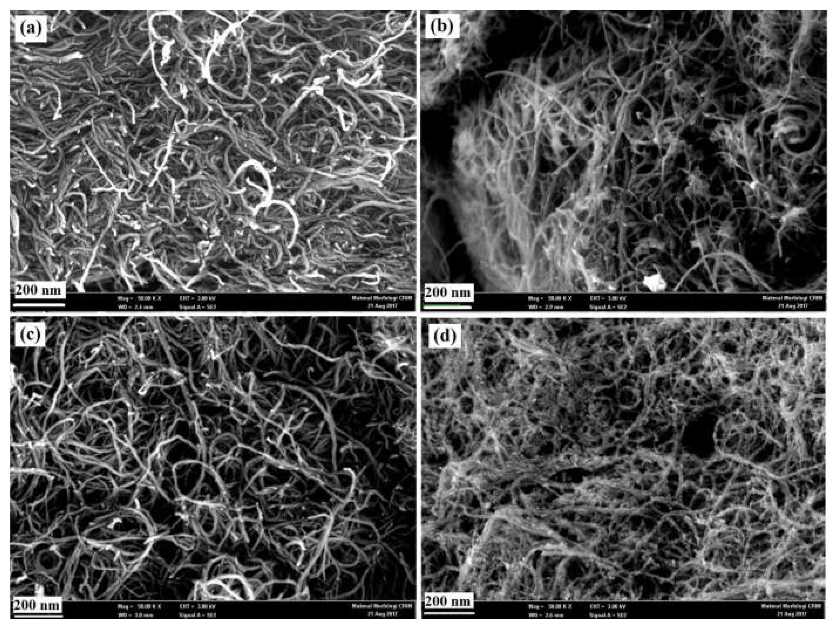
3.1. Surface Morphology

Figure 1 shows the FESEM images of the various electrocatalyst specimens, which were synthesized from the Pt catalyst with different catalyst-supporting materials. Recent studies reported that the Pt catalyst nano-particle was deposited on the catalyst-supporting materials’ surface [33]. Meanwhile, the results conducted on MWCNT-Pt exhibited that a mesh-like structure and carbon nanotubes were entangled with no considerable residue as shown in Figure 1a. In addition, Figure 1b shows the analyzed image of the MWCNT-PBI-Pt electrocatalyst. Results indicated that the Pt nanoparticles were homogeneously deposited on the surface of the MWCNT-PBI nanocomposite because there was no uneven surface detected. Figure 1c shows the MWCNT-Nafion-Pt electrocatalyst in which the nanotubes are evenly distributed. Furthermore, Figure 1d shows the MWCNT-PTFE-Pt electrocatalyst in which limited residues are observed. Moreover, it indicated that the catalyst nanoparticles were evenly distributed. These occurrences were due to the different interaction phenomena between the Pt catalyst and the MWCNT-PTFE nanocomposite materials.

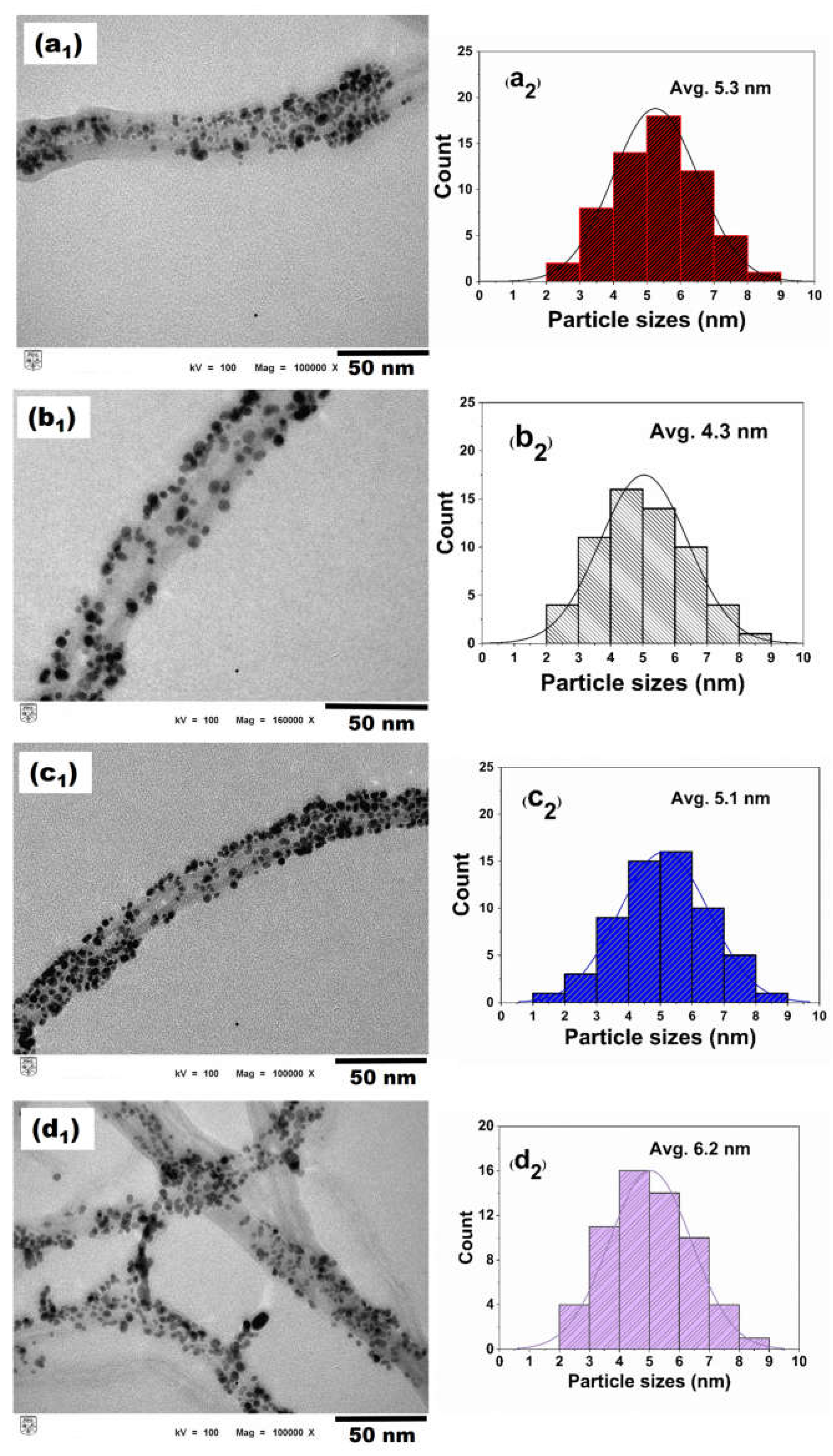
3.2. Surface Topography and Particle Size Distribution

The TEM technique was performed to examine the Pt catalyst deposition onto the various catalyst-supporting materials. Figure 2a1,b1,c1,d1 show the TEM images of the MWCNT-Pt, MWNT-PBI-Pt, MWCNT-Nafion-Pt, and MWCNT-PTFE-Pt, respectively. It can be clearly seen that the Pt nanoparticles were uniformly decorated onto the MWCNTs-based nanocomposite materials’ surfaces. In contrast, Figure 2a2 exhibits a fine distribution of the catalyst particles. This phenomenon was due to the interfacial resistance between the Pt nanoparticles and the catalyst-supporting materials [34].
In addition, MWCNT-PBI-Pt and MWCNT-Nafion-Pt electrocatalysts showed uniform deposition of the catalyst particles on the entire surfaces of the polymer-coated catalyst-supporting materials. These were explained by the fact that the PBI and Nafion polymers acted in reducing the interfacial resistance while functioning as the catalyst binder, which enhanced the bonding between the catalyst and the nanocomposite materials. Despite that, Figure 2d2 shows the MWCNT-PTFE-Pt electrocatalyst in moderate catalyst distribution. This further affected the tendency of the catalyst toward cluster formation, which later led to a catalyst agglomeration.
From Figure 2, the average sizes of the Pt nanoparticles were found as 5.3 ± 0.5 nm, 4.3 ± 0.4 nm, 5.1 ± 0.5 nm, and 6.2 ± 0.6 nm in the MWCNT-Pt, MWCNT-PBI-Pt, MWCNT-Nafion-Pt, and MWCNT-PTFE-Pt electrocatalysts, respectively. These results indicate that the deposited Pt nanoparticles were of different sizes for the various MWCNT-based catalyst-supporting materials. The uneven distribution and agglomeration of catalyst particles could increase the average particle sizes. In contrast, fine distribution reduces the average particle sizes. The TEM analysis reports that few agglomerations have been detected for the MWCNT-PTFE-Pt electrocatalyst which can be reflected in the highest average particle size.

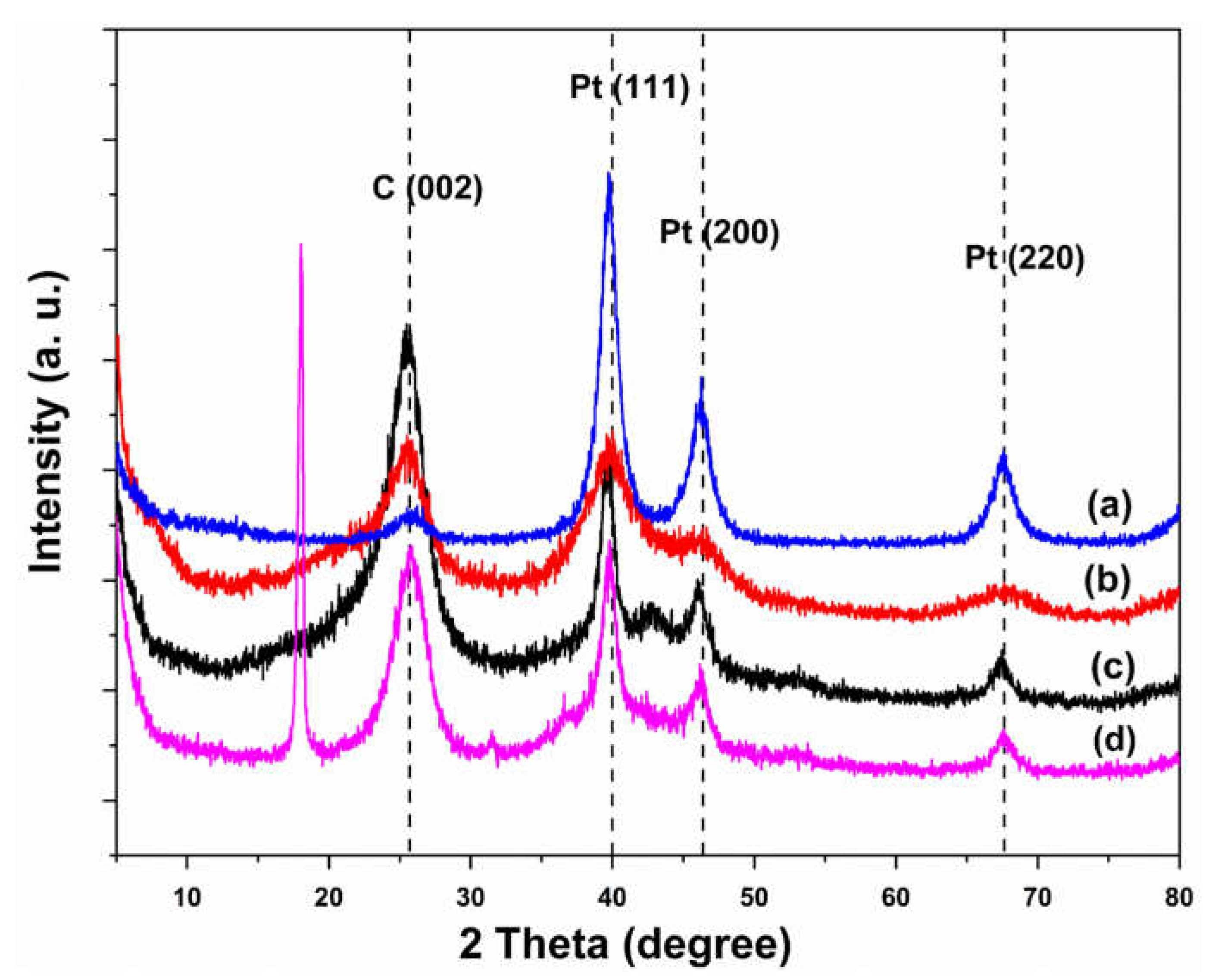
3.3. Determination of Crystalline Phases

Figure 3 shows the XRD patterns of the synthesized electrocatalysts, MWCNTs attributed to graphite with hexagonal structure. It displays a major peak associated with a 2θ of 26° while a minor peak at 43° corresponds to the reflective planes with interlayer spacings d002 and d100 of MWCNT. In addition, it recorded crystallinity and amorphous phases for the MWCNT specimen at 57.5% and 42.5%, respectively [35]. Meanwhile, the MWCNT-PBI-Pt electrocatalyst exhibited five major peaks of 26°, 40°, 43°, 47°, and 68° in 2θ position while the reflection planes were located at d002, d111, d100, d200, and d220, respectively. Based on the studies conducted, the reflection planes of d111, d200, and d220 are attributed to the face-centered cubic (fcc) structure of the Pt deposition on the supporting materials while the d002 reflection plane at 26° indicated the hexagonal structure of the carbon nanotubes.
Despite that, the studies demonstrated that the XRD pattern of the MWCNT-PTFE-Pt electrocatalyst consists of several dominated peaks at 18°, 26°, 32°, 40°, 43°, 47°, and 68° in the 2θ range with the reflection planes of d100, d002, d110, d111, d100, d200, and d220, respectively. However, the peaks at 18° and 32° were detected as the PTFE polymer. Meanwhile, research reported that the peaks of 40°, 47°, and 68° indicated the Pt nanoparticles that were incorporated on the MWCNT nanotube surfaces [36,37]. Furthermore, the MWCNT-Nafion-Pt explicitly demonstrated numerous major peaks at 17°, 26°, 40°, 43°, 47°, and 68° with the reflection planes of d100, d002, d111, d100, d002, and d220, respectively. Among these peaks, the Pt nanoparticles were attributed to the three strong peaks at 40°, 47°, and 68°, which indicated the adhesion of Pt with MWCNT-PTFE-supporting material [38]. Moreover, the crystal sizes were obtained at 5.5 nm, 4.1 nm, 5.3 nm, and 6.3 nm of MWCNT-Pt, MWCNT-PBI-Pt, MWCNT-Nafion-Pt, and MWCNT-Pt specimens, respectively. Again, these crystal sizes were aligned with the results found in the particle size distribution obtained from the TEM analysis. It should be highlighted that the smallest particle size was recorded for the MWCNT-PBI-Pt electrocatalyst.

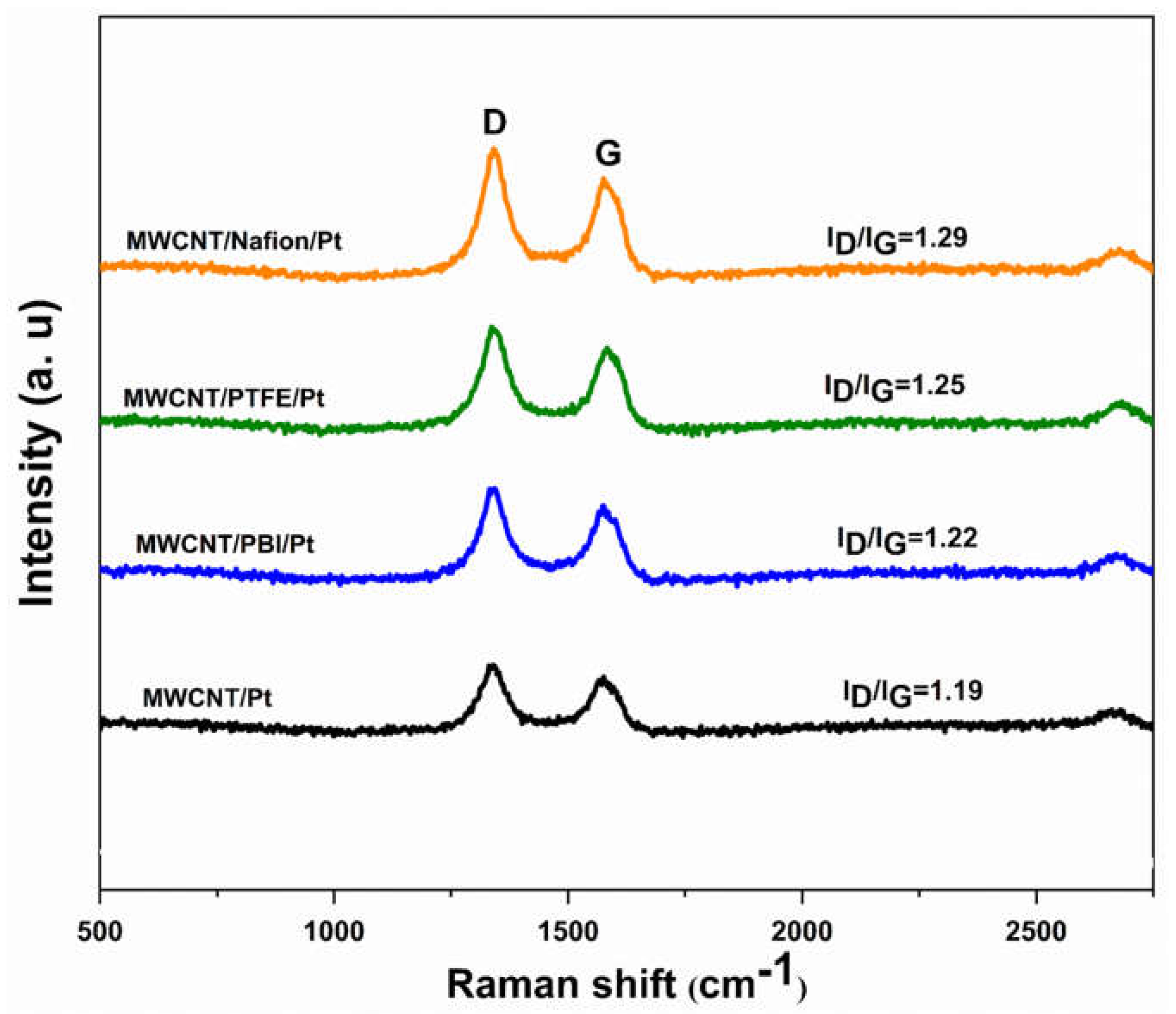
3.4. Chemical Structure Analysis

Raman spectroscopy was performed to investigate the structural defectiveness and degree of deviation of synthesized electrocatalyst specimens. Figure 4 exhibits the two major dominating peaks that explicitly appear at 1345 cm−1 and 1575 cm−1, which are designed as D-band (disorder mode) and G-band (tangential mode), respectively [39]. Studies indicated that the D-band endorsed the amorphous carbon, suggesting the degree of disorder in the carbon nanotubes. Meanwhile, the G-band is ascribed to crystalline graphite carbon, which indicates carbon nanotube purity. Moreover, previous studies suggested that this carbon nanotube purity was related to the lattice structure of all carbon materials [40].
From Figure 4, it is clearly seen that the G-band has a sharp shape, which refers to the high purity of specimens. Meanwhile, the ID/IG ratios were credited to the degree of disorder of the samples or structural defectiveness in the carbon nanotube surfaces [41]. In addition, the ratios obtained for the MWCNT-Pt, MWCNT-PBI-Pt, MWCNT-PTFE-Pt, and MWCNT-Nafion-Pt were 1.19, 1.22, 1.25, and 1.29. However, the interfacial interaction of MWCNT with polymers such as PBI, Nafion, and PTFE can vary due to their different morphological structure. Therefore, MWCNT-Nafion-Pt showed the highest degree of defectiveness while the MWCNT-Pt produced the lowest defectiveness. In addition, these results also clearly indicate the presence of defectiveness within the specimens, which suggested the incorporation of Pt nanoparticles on the surfaces of the polymer-coated MWCNT.

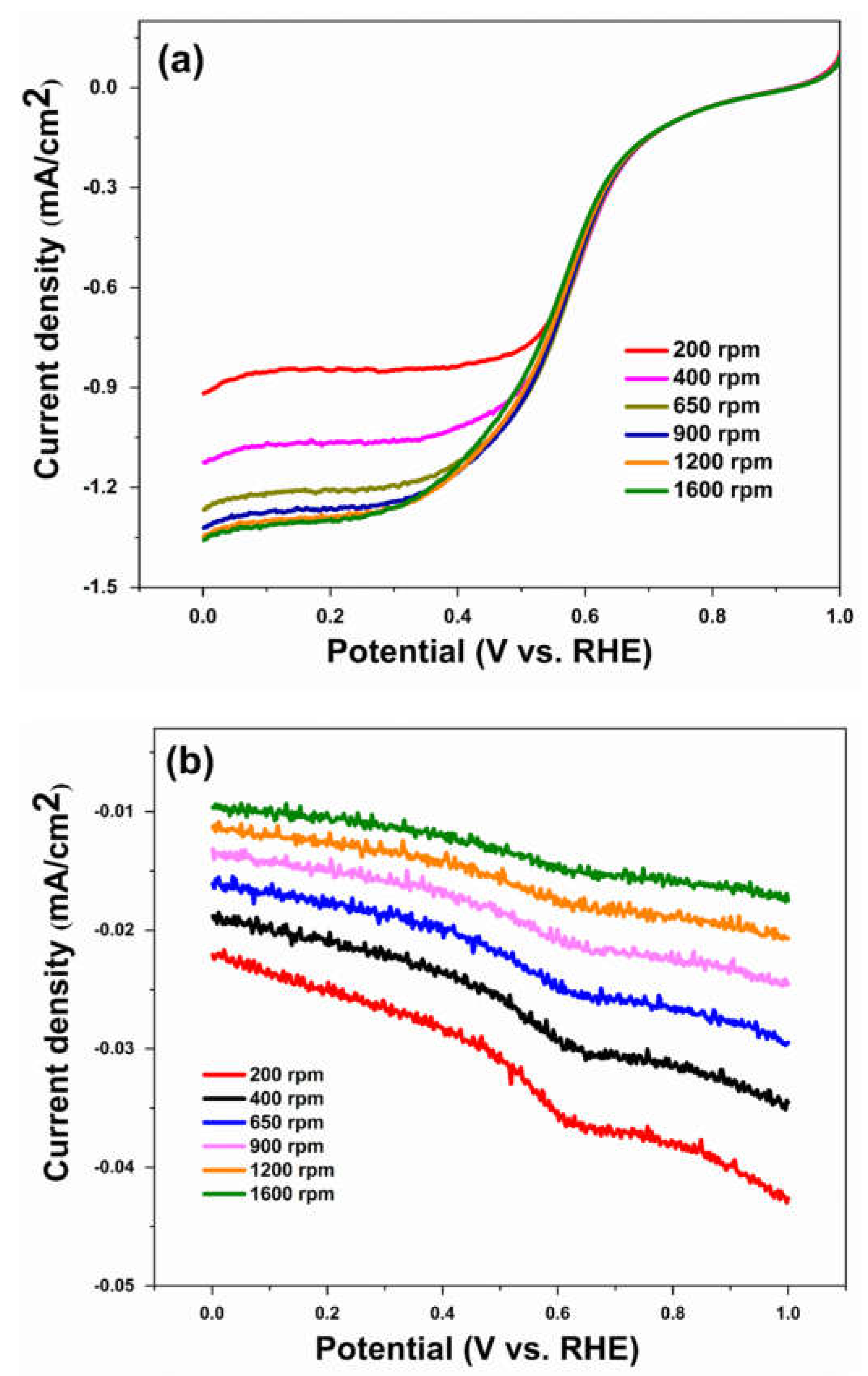
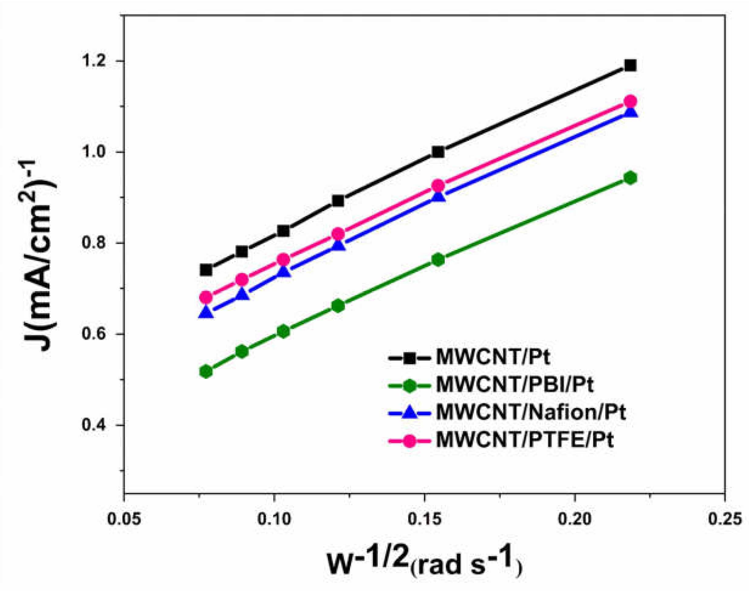
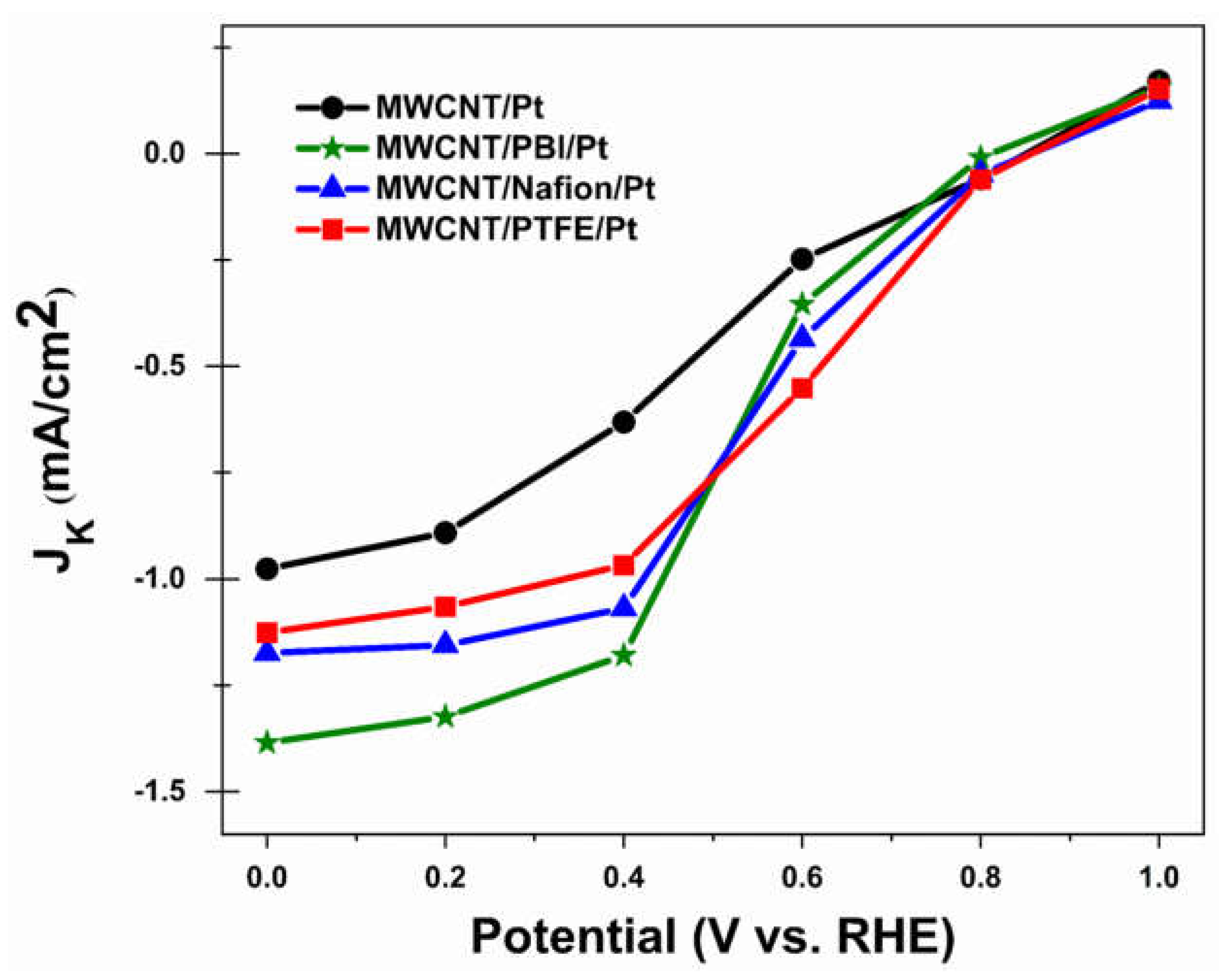
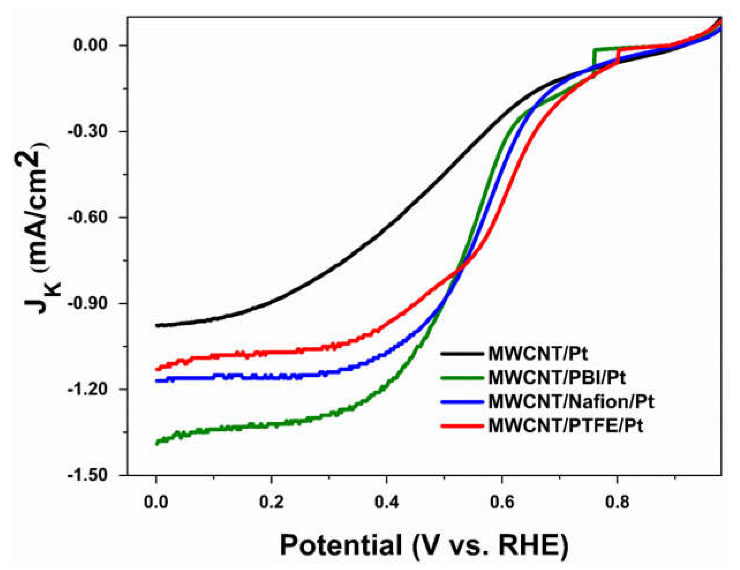
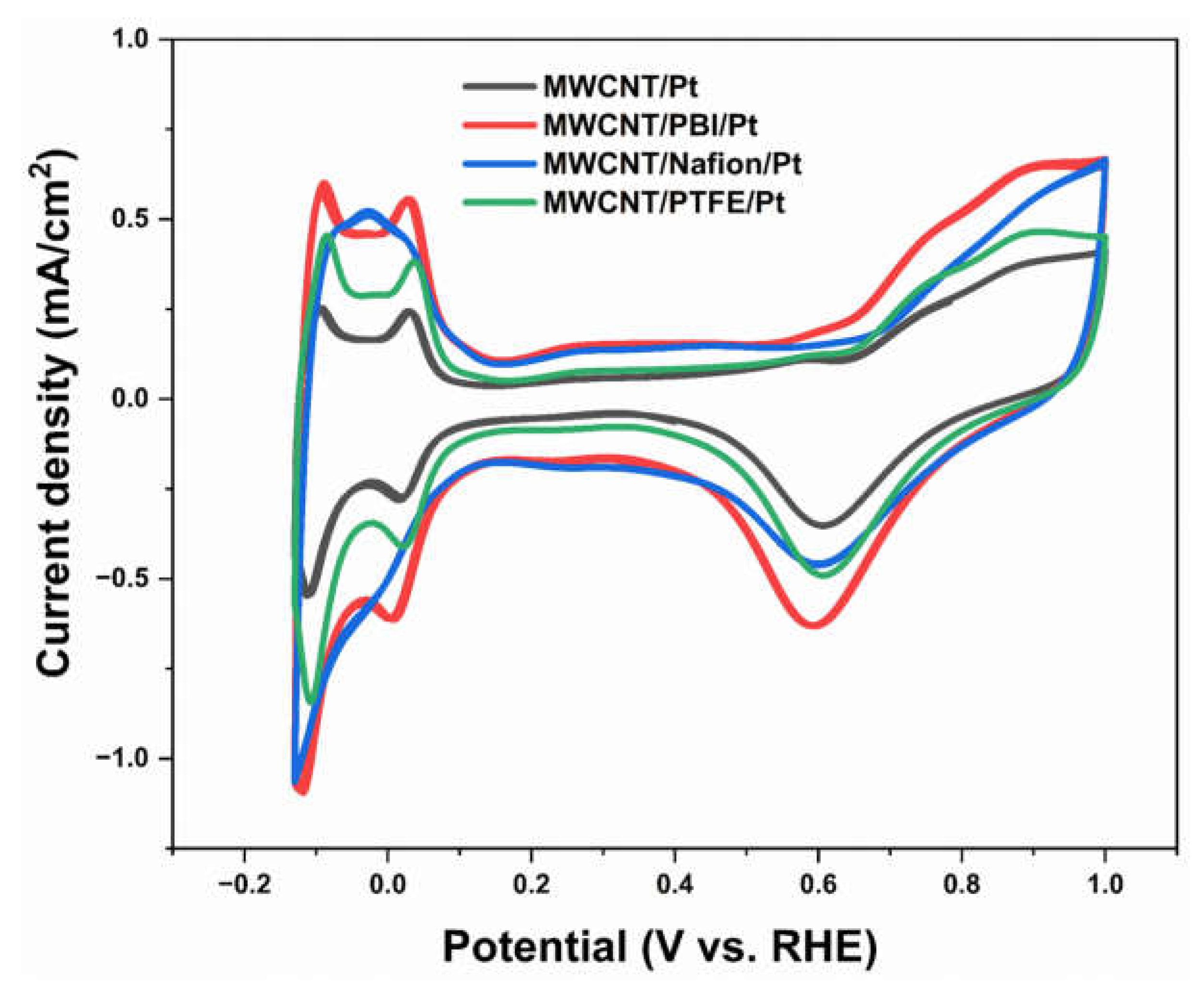
3.5. Electrochemical Analysis

The rotating disk electrode was used to understand the kinetics of ORR using the linear sweep voltammogram curves. According to the Koutchy–Levich equation, the sluggish reaction occurs when the reduction current does not change upon applying a different rotation rate [10]. Recent studies suggested various rotational rates such as 200 rpm, 400 rpm, 650 rpm, 900 rpm, 1200 rpm, and 1600 rpm can be applied. The oxygen reduction current increased with the increase in the rotation rates [42]. Meanwhile, the MWCNT-PBI-Pt was associated with the maximum oxygen reduction current densities while the MWCNT-Pt exhibited minimum oxygen reduction current densities; however, MWCNT-Nafion-Pt showed moderate oxygen reduction current densities. Figure 5a,b show the curves of disk current densities and ring current densities of the MWCNT-Nafion-Pt specimen at various rotation rates. The overall disk current densities increased from −0.85 mA/cm2 to −1.30 mA/cm2 while increasing the rotation rate from 200 rpm to 1600 rpm at an applied potential range of 1.0 V to 0.00 V vs. RHE. In contrast, the ring current densities steadily increased from the potential of 0.6 V to 0.0 V. This phenomenon happened due to the fact that the ring current densities encounter the hydrogen peroxide species which was generated by the ORR [43,44].
Moreover, the Koutchy–Levich plots are constructed according to the linear sweep voltammetry curves as shown in Equation (1) [10].
1 J = 1 J k + 1 0.62 n F C O 2 D O 2 2 3   ν 1 6 ω 1 2
where n represents the electron number consumed by the O2 molecule, F = Faraday constant of 96,485 C mol−1, CO2 = electrolyte oxygen concentration of 1.1 × 10⁻⁶ mol cm−3, DO2 = oxygen diffusion coefficient of 1.4 × 10⁻⁵ cm2 s−1, ʋ = viscosity of H2SO4 electrolyte solution is 0.01 cm2 s−1, and ω = the rotation speed (rad s−1). The value of these variables was obtained from the previous studies [8,10,43,45]. Therefore, the ORR mechanism refers to the catalytic activity. Figure 6 shows the linear Koutchy–Levich plots of the various electrocatalysts considered in this study. It was constructed based on Equation (1), which was calculated from the reduction current densities of respective electrocatalysts using the linear sweep voltammetry curve. This linear relationship indicated that the ORR reactions were first-order reactions regarding the dissolved oxygen concentration [46,47]. In addition, MWCNT-PBI-Pt displayed low reciprocal reduction current densities due to its high reduction current densities. In addition, the MWCNT-Nafion-Pt and MWCNT-PTFE-Pt electrocatalysts displayed moderate reciprocal reduction current densities while MWCNT-Pt provided high reciprocal reduction current density. These results were consistent with their physical properties because of their Pt nanoparticle distribution, different interfacial phenomena of polymer with MWCNTs, and different Id/Ig ratios. Despite that, using the slope of the Koutchy–Levich plots, the total number of electrons transferred was calculated as approximately 4 (four) for every electrocatalyst.
The kinetic limiting current density (JK) of the various electrocatalysts obtained from the intercepts of the Koutchy–Levich plot at different potentials are shown in Figure 7. This JK refers to the reaction rate of ORR on the electrode materials and also provides information regarding the reaction paths [10,48]. Figure 7 shows the kinetic limiting current density (JK) of various electrocatalysts in terms of the potential differences. The values of the JK increased gradually from the starting kinetic limiting current densities until the final kinetic limiting current densities while increasing the applied potential from 1.0 V to 0.0 V. Although this trend of JK of electrocatalysts was different at 0.8 V and 0.6 V potentials, the ultimate JK trend was quite similar for all the specimens. It could happen due to the different surface areas of the catalyst-supporting materials and different ionomer polymer activities in electrocatalysts. In addition, the JK trend in electrocatalysts implies an association of oxygen reduction in a single step which refers to the first-order ORR reaction. Moreover, this result suggests that the ORR reaction involves the four-electron transfer mechanism while the rise in potential also agrees with the Koutchy–Levich plot results.
Watanabe et al. [49] reported that the small sizes of Pt nanoparticles made for a poor diffusion of oxygen. Therefore, not all the Pt surface areas are expected to be available for the ORR. Consequently, the Pt inter-particle distance plays an important role in the increase in Pt mass activity. Cost reduction is the key challenge to the commercialization of fuel cells because of the high cost of noble metals such as Pt catalysts. In addition, the MWCNTs themselves are an expensive catalyst-supporting material. For this reason, MWCNTs were coated by additional polymers such as PBI, Nafion, and PTFE to reduce the mass loading of Pt with MWCNTs, which can be effective for cost reduction. In our electrocatalysts, the distributions of the Pt particle distances obtained >2.0 nm from the TEM images, which had enough space for oxygen diffusion. Moreover, the polymer ionomers can enhance the ORR reaction by associating the mass transfer in the catalyst layer. In addition, the ionomer phase conducts the ionic species to oxygen reduction in the catalyst layer which could be associated with the ORR reaction.
Moreover, the mean electron transfer number (n) and the HO2 species were calculated using Equations (2) and (3), where ID represents the disk current, IR represents the ring current, and N represents the collection efficiency (0.37) [10].
n = 4 I D I D + I R / N
%   H O 2 = 200 I R / N I D + I R / N
Figure 8a shows the electron transfer numbers (n) of the electrocatalysts specimen. Higher n values were found for the electrocatalysts such as 3.83 for MWCNT-Pt, 3.99 for MWCNT-PBI-Pt, 3.84 for MWCNT-Nafion-Pt, and 4.01 for MWCNT-PTFE-Pt at different potentials. These results indicate that the four-electron transfer pathways dominated the ORR reactions, which were also endorsed by the Koutchy–Levich plots. Figure 8b shows the yield % of HO2 species at the various electrocatalysts within the same potential range from 0 V to 0.8 V. The MWCNT-PBI-Pt and the MWCNT-PTFE-Pt electrodes exhibited low HO2 % species at almost zero potential. Meanwhile, the MWCNT-Pt was attributed to 8.62% of the HO2 species within the same potential range from 0.0 V to 0.8 V. The yield of high HO2 % species can be sluggish in the ORR reactions because the high HO2 % species require the additional activation energy of forming the intermediate HO2 % species. At this stage, the HO2 % species was very high for all samples, again sharply decreasing at 0.55 V potential and continuing this phenomenon until zero potential. Based on these results, it can be suggested that the MWCNT-PBI-Pt and MWCNT-PTFE-Pt electrodes are more favorable for the ORR reactions compared to the other electrocatalysts [10].
Figure 9 shows a comparison of the LSV curves of various electrocatalysts attained at the rotation rate of 1200 rpm. The ORR onset potentials of the catalysts were approximately 0.9 V. A more positive onset potential which refers to the fact that the ORR can take place more readily on the surface of these electrocatalysts than on the glassy electrode surface. In addition, Table 1 shows the electrochemical performances of various electrocatalysts. Meanwhile, the kinetic limiting current density plateaus of the MWCNT-PBI-Pt (−1.45 mA/cm2), MWCNT-Nafion-Pt (−1.26 mA/cm2), and MWCNT-PTFE-Pt (−1.16 mA/cm2) were obtained compared to the MWCNT-Pt (−0.96 mA/cm2) under a negative scan window. These indicated that the rate at which the oxygen molecules can reach the surface of these proposed electrodes was faster than the MWCNT-Pt electrocatalyst [10,50]. Finally, it is concluded that the polymer-coated MWCNT-supported Pt-based electrocatalyst exhibits more electrocatalytic activity than the pristine MWCNT-supported Pt-based electrode.
The cyclic voltammogram (CV) was conducted by an autolab potentiostat in a three-electrode system at room temperature (26 °C). This technique is used to assess the electrochemically active surface area (ECSA) of synthesized electrocatalysts, which is considered an electrode performance capability test. Our research group earlier reported that polymer-coated MWCNT nano-composites exhibited high peak currents while pristine MWCNT showed low peak currents [51]. This result demonstrated that with an increase in the surface area of the polymer-coated MWCNT catalyst-supporting materials, the electrochemical activity increases. The produced MWCNT-based nano-composites had a very high surface area that improved electrochemical reactions in the redox process, according to comparable findings from other researchers.
Moreover, Figure 10 displays the CV curves of the Pt-based electrocatalysts supported by polymer/MWCNT that had the following three regions: (a) hydrogen adsorption or desorption, (b) double layer (DL) for capacitive current, and (c) oxygen reduction. The hydrogen oxidation reaction controlled the synthesis of platinum-hydrogen (Pt-H) from about −0.15 V to 0.09 V. As a result of the synthesis of platinum-oxygen (Pt-O), the electrocatalyst revealed the oxygen reduction reaction in the potential range of 0.70 V to 1.0 V. In addition, the polymer-coated MWCNT-supported electrocatalysts provided higher electrochemically active surface area compared to pristine MWCNT-supported electrocatalysts. Despite that, the MWCNT-PBI-Pt demonstrated maximum electrochemical activity (maximum ECSA of 24.31 m2/g) compared to other polymer-coated catalyst-supporting materials presented in Table 1. By comparing the contemporary studies, it can be seen that our synthesized electrocatalysts displayed very satisfactory performance in terms of ECSA, kinetic limiting current density, electron transfer number, and HO2 species. In addition, the electrochemical performance can vary in terms of Pt catalyst mass loading, type of electrolytes with concentrations, and reaction conditions. However, this research extensively reduced the Pt mass loading in the synthesized electrocatalysts compared to other electrocatalysts. Although few studies show high ECSA, they did not considerably reduce Pt mass loading during electrocatalyst synthesis. In addition, our previous studies reported high HO2 species with low Pt mass loading, which was a sluggish ORR rate compared to this study. It also can be clarified that polymer-coated MWCNT-supported electrocatalysts with high surface area contributed to additional Pt catalyst exposure for an electrochemical reaction. Moreover, polymer ionomers such as PBI, Nafion, and PTFE can assist electrochemical interaction by providing high surface areas of the catalyst-supporting material. Based on the results, the overall performance of the polymer-coated electrocatalysts can be ranked in the following order: MWCNT-Pt < MWCNT-PTFE-Pt < MWCNT-Nafion-Pt < MWCNT-PBI-Pt.
Table 1. The electrochemical performance of different electrocatalysts.
Sample ItemsPt
Loading
ECSA (m2/g)JK (mA/cm2)Electrons Transfer (n)% of HO2 SpeciesRef.
MWCNT-Pt0.01 mg/cm217.66−0.96 (at 0.2 V)3.838.62This work
MWCNT-PBI-Pt0.01 mg/cm224.31−1.45 (at 0.2 V)3.990.72This work
MWCNT-Nafion-Pt0.01 mg/cm222.48−1.26 (at 0.2 V)3.847.86This work
MWCNT-PTFE-Pt0.01 mg/cm220.85−1.16 (at 0.2 V)4.010.02This work
MWCNT-PVP-Pt50% (wt.)60.919.33 (at 0.45 V)2.9-[52]
MWCNT-PVP-PWA-Pt50% (wt.)69.935.7 (at 0.45 V)3.9-[52]
MWCNT-PTFE-Pt0.01 mg/cm2-0.28 (at −0.38 V)3.8911.34[53]
MWCNT-Pt0.01 mg/cm2-0.22 (at −0.38 V)3.77-[53]
DWCNT-Pt0.031 mg/cm2-0.88 (at 0.8 V)4.18-[54]
MWCNT-Pt-10.031 mg/cm2-1.72 (at 0.8 V)3.83-[54]
MWCNT-Pt-20.031 mg/cm2-1.30 (at 0.8 V)3.69-[54]

4. Conclusions

This study explores the kinetics of oxygen reduction reactions of synthesized polymer-coated MWCNT-supported Pt-based electrocatalysts. Based on the obtained results, the following conclusions can be drawn:
I.
MWCNT-supported Pt-based electrocatalysts coated with polymers were synthesized successfully by the polyol method which was endorsed by several microstructural and performance characterization techniques such as XRD, Raman spectroscopy, and electrochemical analysis.
II.
TEM image depicts that the Pt nanoparticles were deposited consistently on the polymer-coated MWCNT surfaces with Pt nanoparticle sizes ranging from 4.3 nm to 6.2 nm.
III.
Electron transfer numbers (n) were found to be 3.83 for MWCNT-Pt, 3.99 for MWCNT-PBI-Pt, 3.84 for MWCNT-Nafion-Pt, and 4.01 for MWCNT-PTFE-Pt, which suggests that the ORR reaction mechanism of electrocatalysts is controlled by four electron transfer reaction pathways.
IV.
All modified MWCNT-supported Pt electrocatalysts exhibit high electrochemically active surface areas and limiting current density compared to pristine MWCNT-based Pt electrocatalysts, but the modification by PBI produced the best results.
V.
The kinetics of ORR reactions reveals that the modified MWCNT-based electrocatalysts provide low HO2% species at zero potential while MWCNT-Pt electrocatalysts provide high HO2% species. In addition, the yield of high HO2% species can decrease the ORR.
VI.
The newly developed catalysts, in particular the MWCNT-PBI-Pt, produced higher ORR compared to the traditional ones, indicating greater efficiency in the PEM fuel cell through a reduction in electrode cost and Pt mass loading.
Finally, it can be recommended that the performance of the synthesized polymer-coated MWCNT-supported Pt-based electrocatalysts can be explored for high-temperature PEM fuel cell applications compared to the pristine MWCNT-based Pt catalysts.

Author Contributions

Conceptualization, M.A.H., A.B.S., L.K.S. and R.e.R.; methodology, M.A.H., A.B.S., L.K.S. and R.e.R.; validation, M.M.R., F.I., A.K.C. and J.H.; formal analysis, M.A.H., M.M.R., F.I., A.B.S., L.K.S., R.e.R., A.K.C. and J.H.; investigation, M.A.H., M.M.R., F.I., A.B.S., L.K.S. and R.e.R.; writing—original draft preparation, M.A.H., M.M.R., F.I. and A.K.C.; writing—review and editing, A.B.S., L.K.S., R.e.R. and J.H.; supervision, A.B.S., L.K.S., R.e.R., A.K.C. and J.H.; project administration, A.B.S. and L.K.S.; funding acquisition, A.B.S. and L.K.S. All authors have read and agreed to the published version of the manuscript.

Funding

This work is financially supported by Universiti Kebangsaan Malaysia through University Research Grants (DIP-2020-008).

Data Availability Statement

The data presented in this study are available in the article.

Acknowledgments

The authors would like to thank Universiti Kebangsaan Malaysia for the financial support.

Conflicts of Interest

The authors declare no conflict of interest.

References

  1. Tian, L.; Qiu, G.; Shen, Y.; Wang, X.; Wang, J.; Wang, P.; Song, M.; Li, J.; Li, T.; Zhuang, W.; et al. Carbon Quantum Dots Modulated NiMoP Hollow Nanopetals as Efficient Electrocatalysts for Hydrogen Evolution. Ind. Eng. Chem. Res. 2019, 58, 14098–14105. [Google Scholar] [CrossRef]
  2. Gong, X.; Liu, S.; Ouyang, C.; Strasser, P.; Yang, R. Nitrogen- and Phosphorus-Doped Biocarbon with Enhanced Electrocatalytic Activity for Oxygen Reduction. ACS Catal. 2015, 5, 920–927. [Google Scholar] [CrossRef]
  3. Zhang, J. PEM Fuel Cells and Platinum-Based Electrocatalysts: Encyclopedia of Sustainability Science and Technology; Springer: New York, NY, USA, 2013. [Google Scholar] [CrossRef]
  4. Wong, W.; Daud, W.; Mohamad, A.; Loh, K. Effect of temperature on the oxygen reduction reaction kinetic at nitrogen-doped carbon nanotubes for fuel cell cathode. Int. J. Hydrogen Energy 2015, 40, 11444–11450. [Google Scholar] [CrossRef]
  5. Zhang, J.; Tang, S.; Liao, L.; Yu, W.; Li, J.; Seland, F.; Haarberg, G.M. Improved catalytic activity of mixed platinum catalysts supported on various carbon nanomaterials. J. Power Sources 2014, 267, 706–713. [Google Scholar] [CrossRef]
  6. Gupta, C.; Maheshwari, P.H.; Sasikala, S.; Mathur, R.B. Processing of pristine carbon nanotube supported platinum as catalyst for PEM fuel cell. Mater. Renew. Sustain. Energy 2014, 3, 36. [Google Scholar] [CrossRef]
  7. Galeano, C.; Meier, J.C.; Soorholtz, M.; Bongard, H.; Baldizzone, C.; Mayrhofer, K.J.J.; Schüth, F. Nitrogen-Doped Hollow Carbon Spheres as a Support for Platinum-Based Electrocatalysts. ACS Catal. 2014, 4, 3856–3868. [Google Scholar] [CrossRef]
  8. Toh, S.Y.; Loh, K.S.; Kamarudin, S.K.; Daud, W.R.W. The impact of electrochemical reduction potentials on the electrocatalytic activity of graphene oxide toward the oxygen reduction reaction in an alkaline medium. Electrochimica Acta 2016, 199, 194–203. [Google Scholar] [CrossRef]
  9. Haque, M.A.; Sulong, A.; Loh, K.; Majlan, E.H.; Husaini, T.; Rosli, R.E. Acid doped polybenzimidazoles based membrane electrode assembly for high temperature proton exchange membrane fuel cell: A review. Int. J. Hydrogen Energy 2017, 42, 9156–9179. [Google Scholar] [CrossRef]
  10. Soo, L.T.; Loh, K.S.; Mohamad, A.B.; Daud, W.R.W.; Wong, W.Y. Effect of nitrogen precursors on the electrochemical performance of nitrogen-doped reduced graphene oxide towards oxygen reduction reaction. J. Alloys Compd. 2016, 677, 112–120. [Google Scholar] [CrossRef]
  11. Li, W.; Liang, C.; Zhou, W.; Qiu, J.; Zhou, Z.; Sun, G.; Xin, Q. Preparation and Characterization of Multiwalled Carbon Nanotube-Supported Platinum for Cathode Catalysts of Direct Methanol Fuel Cells. J. Phys. Chem. B 2003, 107, 6292–6299. [Google Scholar] [CrossRef]
  12. Serp, P.; Corrias, M.; Kalck, P. Carbon nanotubes and nanofibers in catalysis. Appl. Catal. A Gen. 2003, 253, 337–358. [Google Scholar] [CrossRef]
  13. Wang, C.; Waje, M.; Wang, X.; Tang, J.M.; Haddon, R.C.; Yan, Y. Proton Exchange Membrane Fuel Cells with Carbon Nanotube Based Electrodes. Nano Lett. 2003, 4, 345–348. [Google Scholar] [CrossRef]
  14. Said, Z.; Rahman, S.; Sharma, P.; Hachicha, A.A.; Issa, S. Performance characterization of a solar-powered shell and tube heat exchanger utilizing MWCNTs/water-based nanofluids: An experimental, numerical, and artificial intelligence approach. Appl. Therm. Eng. 2022, 212, 118633. [Google Scholar] [CrossRef]
  15. AlOtaibi, M.; Alsuhybani, M.; Khayyat, M.; AlOtaibi, B. Performance of Nanocomposites of a Phase Change Material Formed by the Dispersion of MWCNT/TiO2 for Thermal Energy Storage Applications. Materials 2022, 15, 3063. [Google Scholar] [CrossRef]
  16. Balasubramanian, K.; Burghard, M. Chemically Functionalized Carbon Nanotubes. Small 2005, 1, 180–192. [Google Scholar] [CrossRef]
  17. Li, X.; Hsing, I.-M. The effect of the Pt deposition method and the support on Pt dispersion on carbon nanotubes. Electrochimica Acta 2006, 51, 5250–5258. [Google Scholar] [CrossRef]
  18. Wang, S.; Jiang, S.P.; White, T.J.; Guo, J.; Wang, X. Electrocatalytic Activity and Interconnectivity of Pt Nanoparticles on Multiwalled Carbon Nanotubes for Fuel Cells. J. Phys. Chem. C 2009, 113, 18935–18945. [Google Scholar] [CrossRef]
  19. Matsumoto, K.; Fujigaya, T.; Sasaki, K.; Nakashima, N. Bottom-up design of carbon nanotube-based electrocatalysts and their application in high temperature operating polymer electrolyte fuel cells. J. Mater. Chem. 2010, 21, 1187–1190. [Google Scholar] [CrossRef]
  20. Zeis, R. Materials and characterization techniques for high-temperature polymer electrolyte membrane fuel cells. Beilstein J. Nanotechnol. 2015, 6, 68–83. [Google Scholar] [CrossRef] [Green Version]
  21. Tintula, K.K.; Sahu, A.K.; Shahid, A.; Pitchumani, S.; Sridhar, P.; Shukla, A.K. Mesoporous Carbon and Poly(3,4-ethylenedioxythiophene) Composite as Catalyst Support for Polymer Electrolyte Fuel Cells. J. Electrochem. Soc. 2010, 157, B1679. [Google Scholar] [CrossRef]
  22. Yang, Z.; Moriguchi, I.; Nakashima, N. Durable Pt Electrocatalyst Supported on a 3D Nanoporous Carbon Shows High Performance in a High-Temperature Polymer Electrolyte Fuel Cell. ACS Appl. Mater. Interfaces 2015, 7, 9800–9806. [Google Scholar] [CrossRef]
  23. Haque, M.A. Physiochemical Characteristics of Solid Electrolyte Membranes for High-Temperature PEM Fuel Cell. Int. J. Electrochem. Sci. 2019, 14, 371–386. [Google Scholar] [CrossRef]
  24. Rosli, R.; Sulong, A.; Daud, W.W.; Zulkifley, M.; Rosli, M.; Majlan, E.; Haque, M.; Radzuan, N.M. The design and development of an HT-PEMFC test cell and test station. Int. J. Hydrogen Energy 2019, 44, 30763–30771. [Google Scholar] [CrossRef]
  25. Wu, J.; Yuan, X.Z.; Martin, J.J.; Wang, H.; Zhang, J.; Shen, J.; Wu, S.; Merida, W. A review of PEM fuel cell durability: Degradation mechanisms and mitigation strategies. J. Power Sources 2008, 184, 104–119. [Google Scholar] [CrossRef]
  26. Shao, Y.; Yin, G.; Wang, J.; Gao, Y.; Shi, P. Multi-walled carbon nanotubes based Pt electrodes prepared with in situ ion exchange method for oxygen reduction. J. Power Sources 2006, 161, 47–53. [Google Scholar] [CrossRef]
  27. Ye, S.; Hall, M.; Cao, H.; He, P. Degradation Resistant Cathodes in Polymer Electrolyte Membrane Fuel Cells. ECS Trans. 2006, 3, 657–666. [Google Scholar] [CrossRef]
  28. Berber, M.R.; Fujigaya, T.; Sasaki, K.; Nakashima, N. Remarkably Durable High Temperature Polymer Electrolyte Fuel Cell Based on Poly(vinylphosphonic acid)-doped Polybenzimidazole. Sci. Rep. 2013, 3, srep01764. [Google Scholar] [CrossRef]
  29. Su, H.; Pasupathi, S.; Bladergroen, B.; Linkov, V.; Pollet, B.G. Performance Investigation of Membrane Electrode Assemblies for High Temperature Proton Exchange Membrane Fuel Cell. J. Power Energy Eng. 2013, 1, 95–100. [Google Scholar] [CrossRef]
  30. Hafez, I.H.; Berber, M.R.; Fujigaya, T.; Nakashima, N. Enhancement of Platinum Mass Activity on the Surface of Polymer-wrapped Carbon Nanotube-Based Fuel Cell Electrocatalysts. Sci. Rep. 2014, 4, srep06295. [Google Scholar] [CrossRef] [Green Version]
  31. Scheibe, B.; Borowiak-Palen, E.; Kalenczuk, R.J. Oxidation and reduction of multiwalled carbon nanotubes—Preparation and characterization. Mater. Charact. 2010, 61, 185–191. [Google Scholar] [CrossRef]
  32. Spitalsky, Z.; Tasi, D.; Papgelis, K.; Galioti, C. Carbon nanotube-polymer composites: Chemistry, processing mechanical and electrical properties. Prog. Polym. Sci. 2010, 35, 357–401. [Google Scholar] [CrossRef]
  33. Pu, L.; Zou, L.; Zhou, Y.; Zou, Z.; Yang, H. High performance MWCNT–Pt nanocomposite-based cathode for passive direct methanol fuel cells. RSC Adv. 2017, 7, 12329–12335. [Google Scholar] [CrossRef]
  34. Zhang, J.; Xie, Z.; Zhang, J.; Tang, Y.; Song, C.; Navessin, T.; Shi, Z.; Song, D.; Wang, H.; Wilkinson, D.P.; et al. High temperature PEM fuel cells. J. Power Sources 2006, 160, 872–891. [Google Scholar] [CrossRef]
  35. Silva-Carrillo, C.; Reynoso-Soto, E.A.; Félix-Navarro, R.M.; Lin-Ho, S.W.; Díaz-Rivera, A.; Paraguay-Delgado, F.; Chávez-Carvayar, J.; Alonso-Núñez, G. Organic Solvent’s Effect in the Deposition of Platinum Particles on MWCNTs for Oxygen Reduction Reaction. J. Nanomater. 2016, 2016, 5783920. [Google Scholar] [CrossRef]
  36. Kang, W.; Li, F.; Zhao, Y.; Qiao, C.; Ju, J.; Cheng, B. Fabrication of porous Fe2O3/PTFE nanofiber membranes and their application as a catalyst for dye degradation. RSC Adv. 2016, 6, 32646–32652. [Google Scholar] [CrossRef]
  37. Shulga, Y.M.; Vasilets, V.N.; Kiryukhin, D.P.; Voylov, D.N.; Sokolov, A.P. Polymer composites prepared by low-temperature post-irradiation polymerization of C2F4 in the presence of graphene-like material: Synthesis and characterization. RSC Adv. 2015, 5, 9865–9874. [Google Scholar] [CrossRef]
  38. Pandey, M.; Joshi, G.M.; Deshmukh, K.; Khutia, M.; Ghosh, N.N. Optimized AC conductivity correlated to structure, morphology and thermal properties of PVDF/PVA/Nafion composites. Ionics 2014, 20, 1427–1433. [Google Scholar] [CrossRef]
  39. Meng, F.-L.; Jia, Y.; Liu, J.-Y.; Li, M.-Q.; Sun, Y.-F.; Huang, X.-J. Nanocomposites of sub-10 nm SnO2 nanoparticles and MWCNTs for detection of aldrin and DDT. Anal. Methods 2010, 2, 1710–1714. [Google Scholar] [CrossRef]
  40. Zdrojek, M.; Gebicki, W.; Jastrzebski, C.; Melin, T.; Huczko, A. Studies of Multiwall Carbon Nanotubes Using Raman Spectroscopy and Atomic Force Microscopy. Solid State Phenom. 2004, 99–100, 265–268. [Google Scholar] [CrossRef]
  41. Chuang, C.; Huang, J.; Chen, W.; Lee, C.; Chang, Y. Role of amorphous carbon nanowires in reducing the turn-on field of carbon films prepared by microwave-heated CVD. Diam. Relat. Mater. 2004, 13, 1012–1016. [Google Scholar] [CrossRef]
  42. Wong, W.; Daud, W.; Mohamad, A.; Kadhum, A.; Loh, K.; Majlan, E. Recent progress in nitrogen-doped carbon and its composites as electrocatalysts for fuel cell applications. Int. J. Hydrogen Energy 2013, 38, 9370–9386. [Google Scholar] [CrossRef]
  43. Zhang, J.; Xia, Z.; Dai, L. Carbon-based electrocatalysts for advanced energy conversion and storage. Sci. Adv. 2015, 1, e1500564. [Google Scholar] [CrossRef]
  44. Sarapuu, A.; Samolberg, L.; Kreek, K.; Koel, M.; Matisen, L.; Tammeveski, K. Cobalt- and iron-containing nitrogen-doped carbon aerogels as non-precious metal catalysts for electrochemical reduction of oxygen. J. Electroanal. Chem. 2015, 746, 9–17. [Google Scholar] [CrossRef]
  45. Gochi-Ponce, Y.; Alonso-Nuñez, G.; Alonso-Vante, N. Synthesis and electrochemical characterization of a novel platinum chalcogenide electrocatalyst with an enhanced tolerance to methanol in the oxygen reduction reaction. Electrochem. Commun. 2006, 8, 1487–1491. [Google Scholar]
  46. Elezović, N.; Babić, B.; Gajić-Krstajić, L.; Radmilović, V.; Krstajić, N.; Vračar, L. Synthesis, characterization and electrocatalytical behavior of Nb–TiO2/Pt nanocatalyst for oxygen reduction reaction. J. Power Sources 2010, 195, 3961–3968. [Google Scholar] [CrossRef]
  47. Jiang, T.; Brisard, G. Determination of the kinetic parameters of oxygen reduction on copper using a rotating ring single crystal disk assembly (RRDCu(hkl)E). Electrochim. Acta 2007, 52, 4487–4496. [Google Scholar] [CrossRef]
  48. Wu, J.; Zhang, D.; Wang, Y.; Hou, B. Electrocatalytic activity of nitrogen-doped graphene synthesized via a one-pot hydrothermal process towards oxygen reduction reaction. J. Power Sources 2013, 227, 185–190. [Google Scholar] [CrossRef]
  49. Watanabe, M.; Sei, H.; Stonehart, P. The influence of platinum crystallite size on the electroreduction of oxygen. J. Electroanal. Chem. Interfacial Electrochem. 1989, 261, 375–387. [Google Scholar] [CrossRef]
  50. Ponce-De-León, C.; Low, C.T.J.; Kear, G.; Walsh, F.C. Strategies for the determination of the convective-diffusion limiting current from steady state linear sweep voltammetry. J. Appl. Electrochem. 2007, 37, 1261–1270. [Google Scholar] [CrossRef]
  51. Haque, M.; Sulong, A.; Shyuan, L.; Majlan, E.; Husaini, T.; Rosli, R. Synthesis of polymer/MWCNT nanocomposite catalyst supporting materials for high-temperature PEM fuel cells. Int. J. Hydrogen Energy 2020, 46, 4339–4353. [Google Scholar] [CrossRef]
  52. Amyab, S.P.; Saievar-Iranizad, E.; Bayat, A. Platinum nanoparticles with superacid-doped polyvinylpyrrolidone coated carbon nanotubes: Electrocatalyst for oxygen reduction reaction in high-temperature proton exchange membrane fuel cell. RSC Adv. 2016, 6, 41937–41946. [Google Scholar] [CrossRef]
  53. Haque, M.A.; Sulong, A.B.; Majlan, E.H.; Loh, K.S.; Husaini, T.; Rosli, R. Oxygen reduction reaction behaviours of carbon nanotubes supporting pt catalyst for proton exchange membrane fuel cell. Malaysian J. Anal. Sci. 2019, 23, 147–154. [Google Scholar] [CrossRef]
  54. Kuang, H. Development of Carbon Nanotube Supported Pt NPs for Oxygen Reduction of Fuel Cells. Ph.D. Thesis, Curtin University, Perth, Australia, 2017. [Google Scholar]
Figure 1. FESEM images (×50 k; WD = 3 mm; EHT = 3kV) of various electrocatalysts: (a) MWCNT-Pt; (b) MWCNT-PBI-Pt; (c) MWCNT-Nafion-Pt; and (d) MWCNT-PTFE-Pt.
Energies 16 01537 g001
Figure 2. TEM images of various electrocatalysts: (a1) MWCNT-Pt; (b1) MWCNT-PBI-Pt; (c1) MWCNT-Nafion-Pt; and (d1) MWCNT-PTFE-Pt. Pt nanoparticle distribution sizes of (a2) MWCNT-Pt; (b2) MWCNT-PBI-Pt; (c2) MWCNT-Nafion-Pt; and (d2) MWCNT-PTFE-Pt electrocatalysts.
Energies 16 01537 g002
Figure 3. XRD graph of various electrocatalysts: (a) MWCNT-Pt, (b) MWCNT-PBI-Pt, (c) MWCNT-Nafion-Pt, and (d) MWCNT-PTFE-Pt.
Energies 16 01537 g003
Figure 4. Raman spectroscopy analysis of various electrocatalysts.
Energies 16 01537 g004
Figure 5. (a) The disk current density and (b) the ring current density curves of MWCNT-Nafion-Pt electrocatalyst using a rotating disk electrode loaded at various rotation rates in oxygen saturated 1.0 M H2SO4 using 10 mV/s scan rate.
Energies 16 01537 g005
Figure 6. Koutecky–Levich plots of various electrodes.
Energies 16 01537 g006
Figure 7. The kinetic limiting current density (Jk) of various electrocatalysts at different potentials.
Energies 16 01537 g007
Figure 8. (a) The electron transfer number (n) of various electrodes and (b) the percentages (%) of HO2 species of various electrocatalysts.
Energies 16 01537 g008
Figure 9. The linear sweep voltammetry curves of all electrodes in oxygen gas saturated 1.0 M H2SO4 using a 10 mV/s scan rate and a rotation rate at 1200 rpm.
Energies 16 01537 g009
Figure 10. Cyclic voltammogram (CV) of electrocatalysts in oxygen gas saturated 1.0 M H2SO4 using 10 mV/s scan rate.
Energies 16 01537 g010
Disclaimer/Publisher’s Note: The statements, opinions and data contained in all publications are solely those of the individual author(s) and contributor(s) and not of MDPI and/or the editor(s). MDPI and/or the editor(s) disclaim responsibility for any injury to people or property resulting from any ideas, methods, instructions or products referred to in the content.

