
Human Performance Detection Using Operator Action Log of Nuclear Power Plant


Abstract
:1. Introduction
2. Structure Analysis of Operating Procedures
- (1)
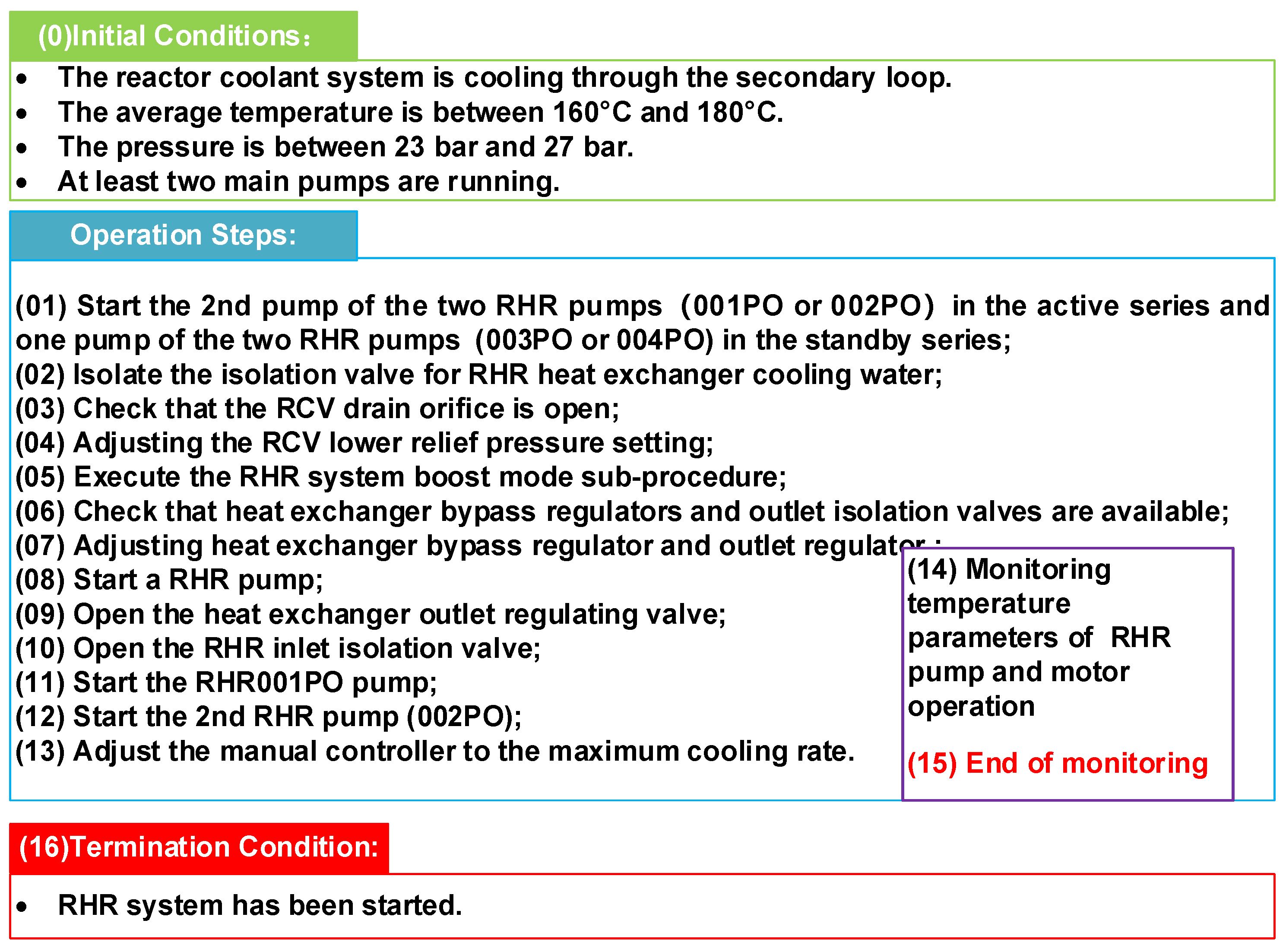
- The reactor coolant system is cooling through the secondary loop.
- (2)
- The average temperature is between 160 °C and 180 °C.
- (3)
- The pressure is between 23 bar and 27 bar.
- (4)
- At least two main pumps are running.
- (a)
- Conditions: conditions under which a step can be performed;
- (b)
- Action: the specific action to be performed;
- (c)
- Objective: the objective to be achieved after the execution of this step.
3. Modeling Operating Procedures at Different Levels
3.1. Overall Structure
- (a)
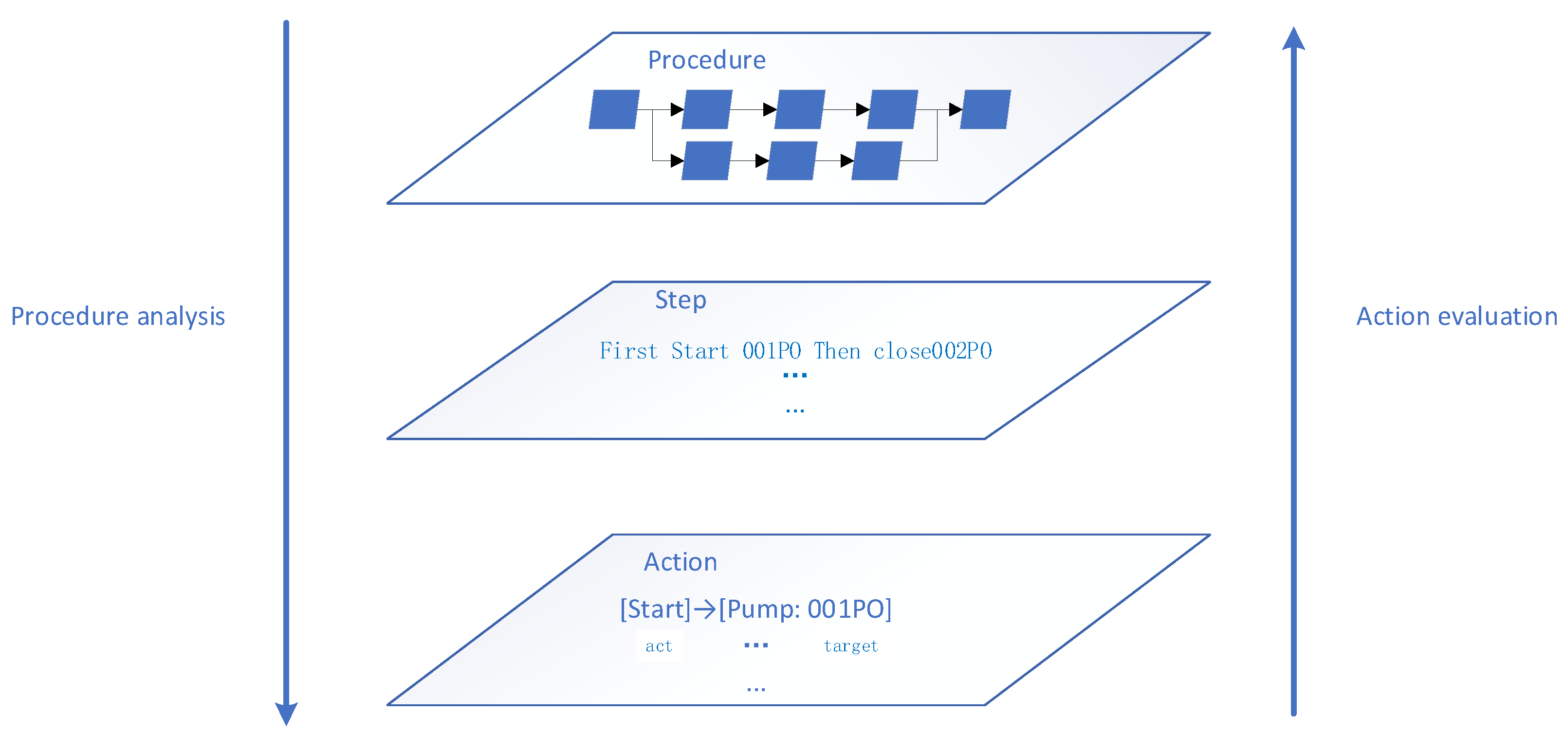
- Procedure level: describes the logical structure of the operating procedure. The operating procedure is composed of steps. The logical structure of the operating procedure determines one or more procedure paths composed of steps. The operator can achieve the objective of the procedure no matter which procedure path is executed.
- (b)
- Step level: indicates the time sequence between the steps involved in completing the procedure. At the step level, the semantics of the procedure steps described in natural language are clarified, including the implementation conditions of the steps, the objectives to be achieved and the timing requirements between steps. During deviation identification, even if the operator has completed the specified steps but the conditions, objectives and timing are not met, these steps will also be identified as deviation.
- (c)
- Action level: represents the actions and objects involved in each step. Some procedures often do not clearly specify the object of an action. For example, step 01 in the procedure shown in Figure 2 “Start the 2nd pump of the two RHR pumps (001PO or 002PO)”. The object of a specific action needs to be determined in combination with the actual operation status of the NPP.
3.2. Procedure Level
3.3. Step Level
3.4. Reasoning of a Compound Step
3.5. Action Level
4. Human Performance Deviation Detection
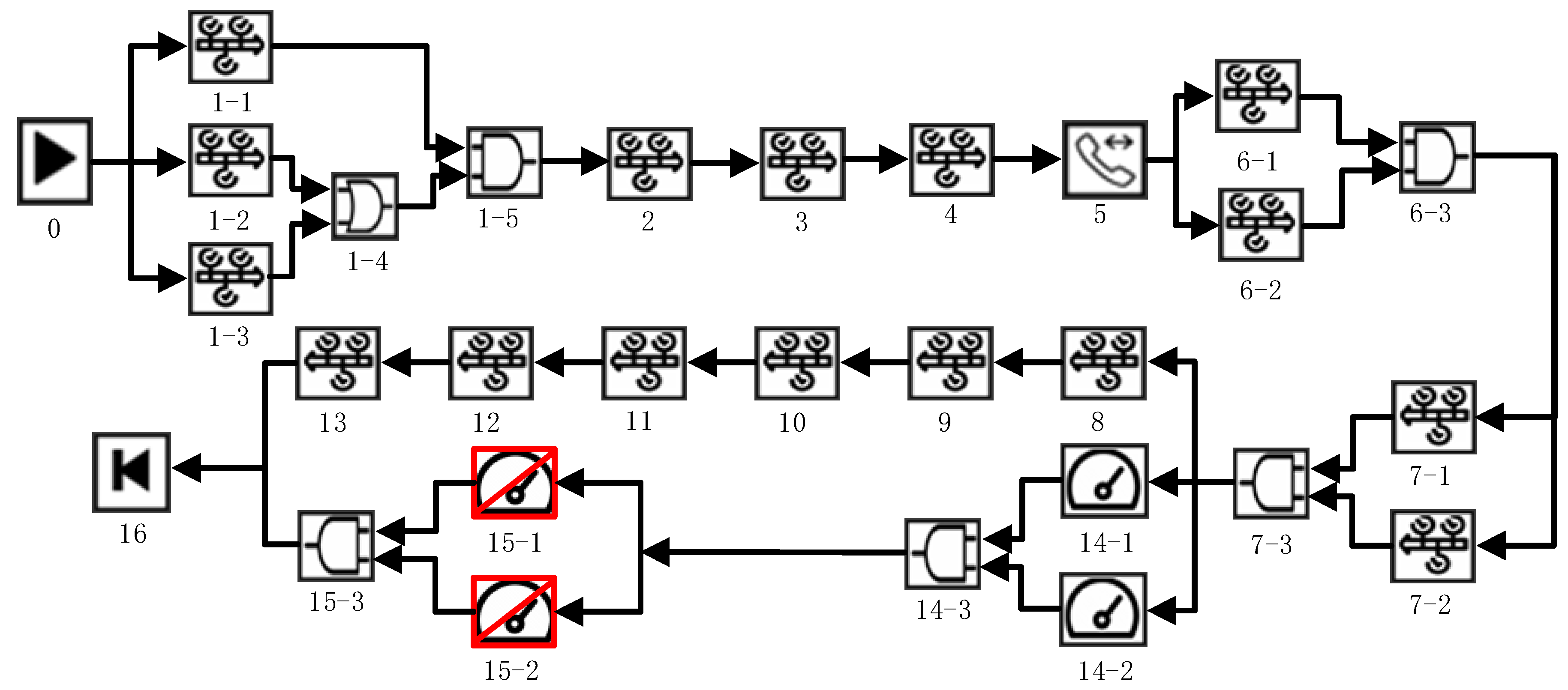
4.1. Action Sequence Identification
- (a)
- Select a new “End Procedure” operator as a starting point.
- (b)
- List the operators one by one forward to form a row until the “Start Procedure” operator.
- (c)
- When encountering an AND logic, list the operators on the input side horizontally. The operators with large numbers are arranged in front, and the operators with small numbers are arranged in the back.
- (d)
- When an OR gate is encountered, copy this row, paste and generate new rows downward. The number of new rows is consistent with the number of inputs of the OR gate.
- (e)
- Repeat steps (a) to (e) until all “End Procedures” have been analyzed.
4.2. Human Performance Deviation Analysis
- (a)
- The identification of executive actions: an operator log contains various I&C control signals converted from executive actions but does not contain direct evidence that the operator is required to observe, confirm and compare other behaviors in the operating procedures. Therefore, it is necessary to separate the execution operations in the operating procedures and compare them with the operator’s log data. The execution actions of action sequences 1 and 2 are identified with a blue background in Table 5. As a result, a standardized procedure template is divided into an executive action template and a non-executive action template.
- (b)
- Actual action sequence detection: read the control commands from the operators in the main control room from the operator log and map them to the standard action codes. Table 6 presents an action sequence example of RHR system startup.
- (c)
- Selection of operating procedure: match the actual action sequence from the operator log with various standardized procedure templates to identify which operating procedure the actual action sequence corresponds to according to the degree of compliance. The degree of compliance is defined as:where A is the total number of actions in the action sequence, and D is the number of deviation actions compared with the procedure template.
- (d)
- Human performance deviation detection: the actual action sequence is compared with the standardized action sequence template. Taking the action sequence provided in Table 6 as an example, it can be seen that the action sequence from the operator log contains two redundant steps, marked with a yellow background.

| Time | Coding |
|---|---|
| 25 February 2019 14:00 | {0401,002PO} |
| 25 February 2019 14:02 | {0403, 003PO} |
| 25 February 2019 14:05 | {0406, RHR011VN} |
| 25 February 2019 14:07 | {0401, 004PO} |
| 25 February 2019 14:10 | {0404, RCV 409KC} |
| 25 February 2019 14:13 | {0601, PRHR} |
| 25 February 2019 14:20 | {0405, RCV013VP,} |
| 25 February 2019 14:20 | {0405, RCV024VP} |
| 25 February 2019 14:21 | {0401, RHR002PO} |
| 25 February 2019 14:24 | {0401, RCP0VP} |
| 25 February 2019 14:25 | {0401, RHR120VP} |
| 25 February 2019 14:28 | {0402, 004PO} |
| 25 February 2019 14:29 | {0401, RHR001PO} |
| 25 February 2019 14:30 | {0401, RHR002PO} |
| 25 February 2019 14:39 | {0404,024VP} |
5. Discussion
6. Conclusions
Author Contributions
Funding
Data Availability Statement
Conflicts of Interest
References
- Niu, Z.B.; Wu, J.Q.; Liu, X.F.; Huang, L.Z.; Nielsen, P.S. Understanding energy demand behaviors through spatio-temporal smart meter data analysis. Energy. 2021, 226, 120493. [Google Scholar]
- O’Hara, I.; Brown, W. The Effects of Interface Management Tasks on Crew Performance and Safety in Complex Computer Based Systems; NUREG/CR-6633; NRC: Washington, DC, USA, 2002. [Google Scholar]
- Braseth, A.O.; Nihlwing, C. Lessons learned from Halden Project Research on human system. Nucl. Eng. Technol. 2009, 41, 215–224. [Google Scholar] [CrossRef]
- Gwi, S.J.; Kwang, S.S.; Seung, H.S. Operator action log based monitoring and control and its verification of nuclear power plants. Ann. Nucl. Energy 2021, 151, 107939. [Google Scholar]
- O’Hara, J.M.; Higgins, J.C.; Stubler, W.F.; Kramer, J. Computer-Based Procedure Systems: Technical Basis and Human Factors Review Guidance; NUREG/CR-6634; NRC: Washington, DC, USA, 2000. [Google Scholar]
- O’Hara, J.M.; Brown, W.S. Nuclear Regulatory Commission. NUREG 0700 (Rev. 2). In Human-System Interface Design Review Guidelines; Nuclear Regulatory Commission Office of Nuclear Regulatory Research: Rockville, MD, USA, 2002. [Google Scholar]
- Yang, D.W.; Liu, H.W. Application of THERP HCR Model for Valve Overhaul in Nuclear Power Plant. In Proceedings of the International Conference on Materials Science, Energy Technology, Power Engineering, Hangzhou, China, 25–27 August 2017. [Google Scholar]
- Laumann, K.; Rasmussen, M. Suggested improvements to the definitions of Standardized Plant Analysis of Risk-Human Reliability Analysis (SPAR-H) performance shaping factors, their levels and multipliers and the nominal tasks. Reliab. Eng. Syst. Saf. 2015, 145, 287–300. [Google Scholar] [CrossRef]
- Pan, X.; Wang, H.X.; Lin, Y.; Liu, T.; Wang, X.X. HEP quantification strategy based on modified CREAM. J. Syst. Eng. Electron. 2019, 30, 815–822. [Google Scholar]
- O’Hara, J.M.; Higgins, J.; Persensky, J.; Lewis, P.; Bongarra, J. Human Factors Engineering Program Review Model; NUREG 00711; NRC: Washington, DC, USA, 2002. [Google Scholar]
- Al Rashdan, A.; St. Germain, S. Methods of data collection in nuclear power plants. Nucl. Technol. 2019, 205, 1062–1074. [Google Scholar] [CrossRef]
- Pei, H.; Liu, W.; Tang, D. Unified Auditing Technical Framework under Big Data. Commun. Technol. 2020, 53, 2252–2256. [Google Scholar]
- Anton, A.C.; Kevin, J.S.; Christopher, P. Logging and Log Management: The Authoritative Guide to Understanding the Concepts Surrounding Logging and Log Management; Syngress Publishing: Rockland, MA, USA, 2012. [Google Scholar]
- Han, J.; Kamber, M.; Pei, J. Data Mining: Concepts and Techniques, 3rd ed.; Morgan Kaufmann Publishing Co.: San Mateo, CA, US, 2012. [Google Scholar]
- Sowa, J.F. Conceptual Structures: Information Processing in Mind and Machine; Addison Westly Publishing Co.: Boston, MA, USA, 1984. [Google Scholar]
- Sowa, J.F.; Way, E.C. Implementing a semantic interpreter using conceptual graph. IBM J. Res. Dev. 1986, 30, 57–69. [Google Scholar] [CrossRef]

| Type | Symbols | Operator | Explanation |
|---|---|---|---|
| 01 |  | Conditions | Condition requirements |
| 02 |  | End Conditions | End of condition requirements |
| 03 |  | Start Procedure | The start of a procedure |
| 04 |  | Step | A step of a procedure |
| 05 |  | End Procedure | The end of a procedure |
| 06 |  | Synchronous Call | One procedure calls another procedure, which cannot continue executing until the call returns. |
| 07 |  | Asynchronous Call | A procedure calls another procedure, which can continue executing without waiting for the call to return. |
| 08 |  | Start Sub-procedure | The start of a sub-procedure |
| 09 |  | End Sub-procedure | The end of a sub-procedure |
| 10 |  | Title | A note on a step (optional) |
| 11 |  | OR | Logic of “OR” |
| 12 |  | AND | Logic of “AND” |
| 13 |  | Wait | Wait until the specified conditions are met before performing the following steps. |
| 14 |  | End Wait | The end of a Wait operator |
| 15 |  | Monitor | Monitor whether the specified conditions are met while performing the following steps. |
| 16 |  | End Monitor | The end of a Monitor operator |
| 17 |  | Remove Monitor | Remove a condition monitoring requirement. |
| 18 |  | IF | Logic of “if” |
| 19 |  | ELSE | Logic of “else” |
| 20 |  | END IF | The end of an IF operator |
| 21 |  | Optional | Whether a step is executed is optional. |
| 22 |  | Timer | Timer to specify a monitoring period |
| 23 |  | End Timer | The end of a timer |
| 24 |  | Remove Timer | Remove a timer |
| No. | Operator | Explanation |
|---|---|---|
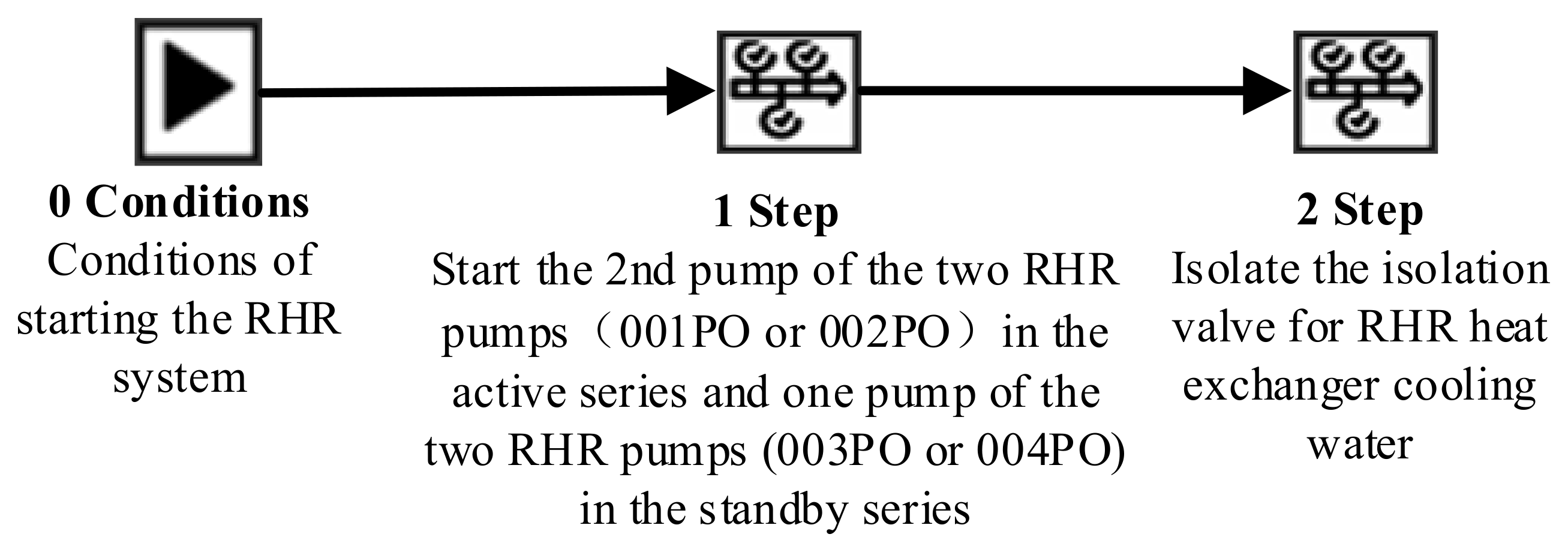
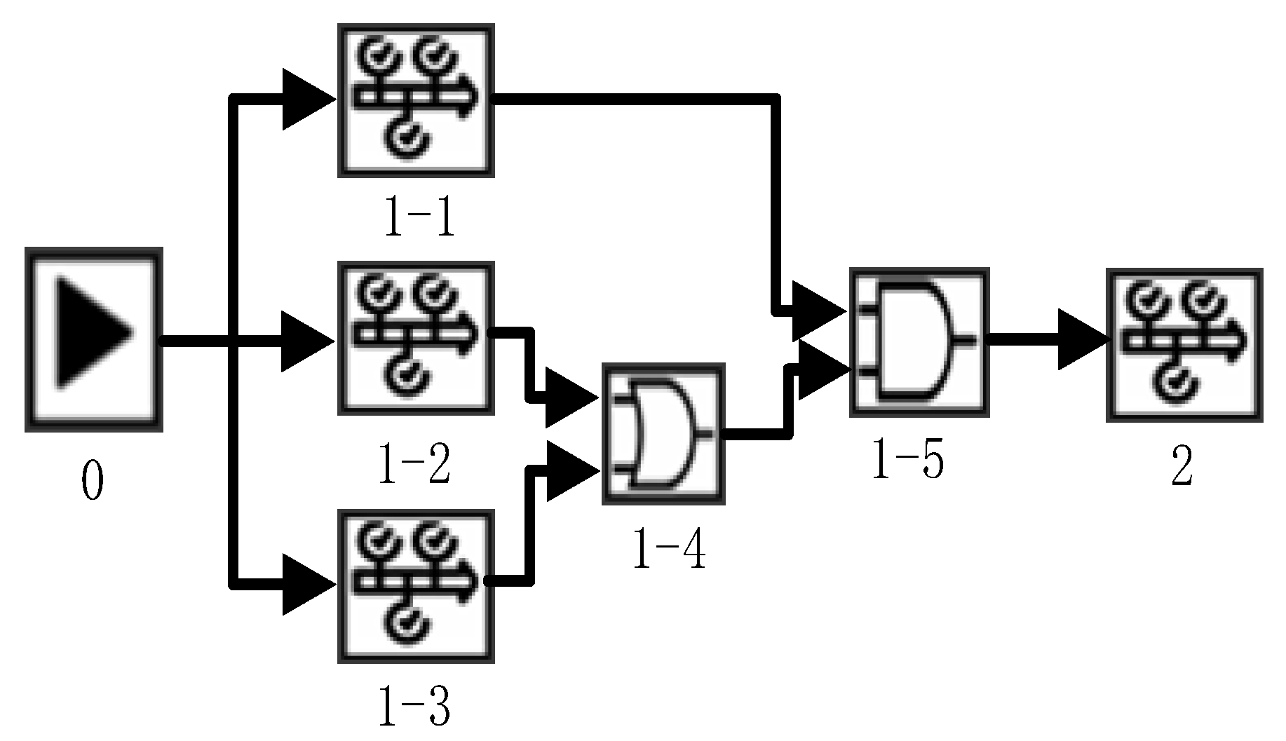
| 0 | Conditions | Conditions of starting the RHR system |
| 1-1 | Step | Start the 2nd RHR pump |
| 1-2 | Step | Stand by the 003PO pump |
| 1-3 | Step | Stand by the 004PO pump |
| 1-4 | OR | Stand by either the 003PO or 004PO pump |
| 1-5 | AND | Start the 002PO and stand by the 003PO or 004PO pump |
| 2 | Step | Isolate the isolation valve for RHR heat exchanger cooling water |
| Type | Action | Coding |
|---|---|---|
| 01 Conditions | Conditions | 0101 |
| 02 End Conditions | End Conditions | 0201 |
| 03 Start Procedure | Start Procedure | 0301 |
| 04 Step | Open/Start | 0401 |
| Close | 0402 | |
| Back up | 0403 | |
| Adjust | 0404 | |
| Check | 0405 | |
| Isolate | 0406 | |
| Match | 0407 | |
| Check Open | 0408 | |
| 05 End Procedure | End Procedure | 0501 |
| 06 Synchronous Call | Start up | 0601 |
| … | … | … |
| 11 Or | Or | 1101 |
| 12 And | And | 1201 |
| … | … | … |
| 15 Monitor | Monitor | 1501 |
| 16 End Monitor | End Monitor | 1601 |
| … | … | … |
| No. | Standard Actions | Coding |
|---|---|---|
| 0 | [start procedure]→[temperature: T1,T2]& [pressure: P1]& [pump:1PO,2PO] | {0301, T1, T2, P1, 1PO, 2PO} |
| 1-1 | [start]→[pump:002PO] | {0401,002PO} |
| 1-2 | [back up]→[pump:003PO] | {0403, 003PO} |
| 1-3 | [back up]→[pump:004PO] | {0403, 004PO} |
| 1-4 | AND | {1101} |
| 1-5 | OR | {1201} |
| 2 | [Isolate]→[valve: RHR011VN] | {0406, RHR011VN} |
| Knowledge Graphs at Step Level | Action Codes at Action Level | ||||||
|---|---|---|---|---|---|---|---|
| Sequence 1 | Sequence 2 | Sequence 1 | Sequence 2 | ||||
| No. | Standard Actions | No. | Standard Actions | No. | Coding | No. | Coding |
| 0 | [start sub-procedure]→[temperature: T1,T2]& [pressure:P1] & [pump:1PO,2PO] | 0 | [start procedure]→[temperature: T1,T2]& [pressure:P1] & [pump:1PO,2PO] | 0 | {0301, T1, T2, P1,1PO,2PO} | 0 | {0301, T1, T2, P1,1PO,2PO} |
| 1-1 | [start]→[pump:002PO] | 1-1 | [start]→[pump:002PO] | 1-1 | {0401,002PO} | 1-1 | {0401,002PO} |
| 1-2 | [back up]→[pump:003PO] | 1-2 | [back up]→[pump:004PO] | 1-2 | {0403, 003PO} | 1-2 | {0403, 004PO} |
| 2 | [Isolate]→[valve: RHR011VN] | 2 | [Isolate]→[valve: RHR011VN] | 2 | {0406, RHR011VN} | 2 | {0406, RHR011VN} |
| 3 | [Check Open]→[letdown orifice: RCV007VP] | 3 | [Check Open]→[letdown orifice: RCV007VP] | 3 | {0408, RCV007VP} | 3 | {0408, RCV007VP} |
| 4 | [Adjust]→[pressure: RCV 409KC] | 4 | [Adjust]→[pressure: RCV 409KC] | 4 | {0404, RCV 409KC} | 4 | {0404, RCV 409KC} |
| 5 | [Start up]→[Sub-procedures: PRHR] | 5 | [Start up]→[Sub-procedures: PRHR] | 5 | {0601, PRHR} | 5 | {0601, PRHR} |
| 6-1 | [Check]→[valve: RCV013VP] | 6-1 | [Check]→[valve: RCV013VP] | 6-1 | {0405, RCV013VP,} | 6-1 | {0405, RCV013VP,} |
| 6-2 | [Check]→[valve: RCV024VP] | 6-2 | [Check]→[valve: RCV024VP] | 6-2 | {0405, RCV024VP} | 6-2 | {0405, RCV024VP} |
| 7-1 | [Adjust]→[valve: RCV013VP] | 7-1 | [Adjust]→[valve: RCV013VP] | 7-1 | {0404, RCV013VP} | 7-1 | {0404, RCV013VP} |
| 7-2 | [Adjust]→[valve: RCV024VP] | 7-2 | [Adjust]→[valve: RCV024VP] | 7-2 | {0404, RCV024VP} | 7-2 | {0404, RCV024VP} |
| 8 | [Open]→[pump: RHR002PO] | 8 | [Open]→[pump: RHR002PO] | 8 | {0401, RHR002PO} | 8 | {0401, RHR002PO} |
| 14-1 | [Monitor]→[temperature: TRHR001PO] | 14-1 | [Monitor]→[temperature: TRHR001PO] | 14-1 | {1501, TRHR001PO} | 14-1 | {1501, TRHR001PO} |
| 14-2 | [Monitor]→[temperature: T013M] | 14-2 | [Monitor]→[temperature: T013M] | 14-2 | {1501, T013M} | 14-2 | {1501, T013M} |
| 9 | [Open]→[valve: RCP0VP] | 9 | [Open]→[valve: RCP0VP] | 9 | {0401, RCP0VP} | 9 | {0401, RCP0VP} |
| 10 | [Open]→[valve: RHR120VP] | 10 | [Open]→[valve: RHR120VP] | 10 | {0401, RHR120VP} | 10 | {0401, RHR120VP} |
| 11 | [Open]→[ pump: RHR001PO] | 11 | [Open]→[ pump: RHR001PO] | 11 | {0401, RHR001PO} | 11 | {0401, RHR001PO} |
| 12 | [Open]→[ pump: RHR002PO] | 12 | [Open]→[pump: RHR002PO] | 12 | {0401, RHR002PO} | 12 | {0401, RHR002PO} |
| 13 | [Adjust]→[manual controller: 024VP] | 13 | [Adjust]→[manual controller: 024VP] | 13 | {0404,024VP} | 13 | {0404,024VP} |
| 15-1 | [End Monitor]→[temperature: TRHR001PO] | 15-1 | [End Monitor]→[temperature: TRHR001PO] | 15-1 | {1601, TRHR001PO} | 15-1 | {1601, TRHR001PO} |
| 15-2 | [End Monitor]→[temperature: T013M] | 15-2 | [End Monitor]→[temperature: T013M] | 15-2 | {1601, T013M} | 15-2 | {1601, T013M} |
| 16 | [Suit]→[valve: RHR] | 16 | [Suit]→[valve: RHR] | 16 | {0501, RHR} | 16 | {0501, RHR} |
Disclaimer/Publisher’s Note: The statements, opinions and data contained in all publications are solely those of the individual author(s) and contributor(s) and not of MDPI and/or the editor(s). MDPI and/or the editor(s) disclaim responsibility for any injury to people or property resulting from any ideas, methods, instructions or products referred to in the content. |
© 2023 by the authors. Licensee MDPI, Basel, Switzerland. This article is an open access article distributed under the terms and conditions of the Creative Commons Attribution (CC BY) license (https://creativecommons.org/licenses/by/4.0/).
Share and Cite
Dai, X.; Yang, M.; Wang, J.; Xu, Z.; Wen, H. Human Performance Detection Using Operator Action Log of Nuclear Power Plant. Energies 2023, 16, 1573. https://doi.org/10.3390/en16041573
Dai X, Yang M, Wang J, Xu Z, Wen H. Human Performance Detection Using Operator Action Log of Nuclear Power Plant. Energies. 2023; 16(4):1573. https://doi.org/10.3390/en16041573
Chicago/Turabian StyleDai, Xinyu, Ming Yang, Jipu Wang, Zhihui Xu, and Hanguan Wen. 2023. "Human Performance Detection Using Operator Action Log of Nuclear Power Plant" Energies 16, no. 4: 1573. https://doi.org/10.3390/en16041573
APA StyleDai, X., Yang, M., Wang, J., Xu, Z., & Wen, H. (2023). Human Performance Detection Using Operator Action Log of Nuclear Power Plant. Energies, 16(4), 1573. https://doi.org/10.3390/en16041573