Review

Review on Plasma-Assisted Ignition Systems for Internal Combustion Engine Application

1
Department of Mechanical Engineering, Mississippi State University, Mississippi State, MS 39762, USA
2
Center for Advanced Vehicular Systems (CAVS), Starkville, MS 39759, USA
*
Author to whom correspondence should be addressed.
Energies 2023, 16(4), 1604; https://doi.org/10.3390/en16041604
Submission received: 16 December 2022 / Revised: 20 January 2023 / Accepted: 26 January 2023 / Published: 6 February 2023

Abstract

:
Due to the depletion of conventional petroleum-based fuels and increasing environmental concerns, industries have been developing new combustion technologies with acceptable cost ranges and minimum system modifications for consumers. Among many approaches, the utilization of plasma ignition systems is considered as a promising pathway to achieve greener transportation while maintaining conventional internal combustion engine systems. Plasma contains highly reactive radicals, and those have a great potential of enhancing chemical reactions that are beneficial for reducing carbon emissions. The primary objective of this paper is to provide an overview of currently available plasma-assisted combustion systems including recent achievements in research and development, and technical challenges for successfully implementing a new ignition system. This review will introduce various plasma-assisted combustion approaches from worldwide projects, covering non-thermal and thermal plasma systems in internal combustion engines.

1. Introduction

Heat engines convert the thermal energy of fuel into mechanical work by burning fuel. Since the invention of the internal combustion (IC) engines, they have been utilized in a wide range of transportation and power generation sectors such as for automobiles, ships, aircrafts, and generators for producing electrical energy. However, due to environmental issues such as the continuous increase in oil prices and global warming, the demand for eco-friendly and high-efficiency internal combustion engines are increasing. Approximately 27% of the total CO2 emission originates from the transportation sector, so the regulations on CO2 emission in the automobile sector are becoming stricter [1]. It is noted that the CO2 emissions are directly related to vehicle fuel efficiency and greenhouse gas emission levels. Therefore, it is essential to develop innovative combustion technologies to reduce CO2 emissions.
Gasoline engines can be applied to various fields because they produce less noise and vibration compared to diesel engines, can be reduced in weight and size, and are easy to run at high speeds. In addition, gasoline engines have fewer concerns with respect to particulate matter (PM) than in diesel engines thanks to their relatively homogeneous air–fuel mixture [2]. However, since gasoline engines have technical issues with combustion stability and knocking, they are driven at a low compression ratio. Thus, the fuel consumption of diesel engines is better than that of gasoline engines. To compensate for this disadvantage, direct-injection spark ignition (DISI) engines that directly inject fuel into the combustion chamber have been applied [3,4]. The DISI engines can be run with a higher compression ratio and volumetric efficiency thanks to the evaporation cooling of directly injected liquid fuel into the combustion chamber. In particular, the stratified combustion DISI engine that burns a stratified mixture around the spark plug has shown excellent combustion stability even under the lean burn condition [5]. Thus, further improvement in fuel consumption can be achieved. In addition, since the DISI engine directly injects fuel into the cylinder, there is no delay and precise air–fuel ratio control is possible compared to the port fuel injection (PFI), which injects fuel into the intake port [6].
In terms of exhaust emissions, in the case of DISI engines, a lesser amount of unburned hydrocarbon (HC) emissions are generated compared to PFI engines, in which a fuel film is formed on the wall of the intake port. On the other hand, oil dilution, deposits in injectors, and cost increases due to high-pressure fuel injection devices and controllers remain to be resolved issues for DISI engines [7,8]. Currently, DISI engines are being developed with advanced combustion technologies such as lean burn, exhaust gas recirculation (EGR), and turbochargers [9,10,11]. However, as these technologies are applied, the combustion stability deteriorates. According to previous research, the minimum ignition energy increases as the equivalence ratio decreases from around 1.0, the flow velocity of the mixer increases, and the possibility of misfire or partial burn in engine operation has been reported to increase. Peterson et al. investigated the misfire/partial burn tendency according to the spark ignition energy based on the flow rate and distribution of the mixture inside the combustion chamber of a spray-guided (SG)-DISI gasoline visualization engine [12]. It was revealed that the lower the spark ignition energy, the higher the probability of abnormal combustion, as shown in Figure 1.
To overcome this technical issue, studies are being conducted to develop and apply a new ignition system with a larger initial flame kernel than the conventional spark plug. Most of the research is focused on developing a combustor that can implement a wider initial plasma channel within the combustion system and investigating the flame propagation speed, combustion stability, and flammability limit. Previous studies reported a faster flame propagation speed and expansion of the flammability limit compared to the conventional spark ignition system. However, there needs to be more studies that apply the plasma ignition system in a real-engine environment. In addition, primary data and efficiency analyses are required to prove the validity of the developed system. Therefore, to achieve the purpose of reducing CO2 more successfully and improving combustion stability by applying the plasma-assisted ignition system to a direct injection gasoline engine, system optimization through fundamental design, implementation of the ignition system, and experiments under various conditions are needed. To this end, this review paper aims to provide detailed information and perspective on the plasma-assisted combustion studies. So far, major studies have been organized according to the main parameters, immediate results, and energy per event. In addition to plasma-assisted combustion, studies on novel ignition and combustion methods were also reviewed.

2. Plasma-Assisted Combustion

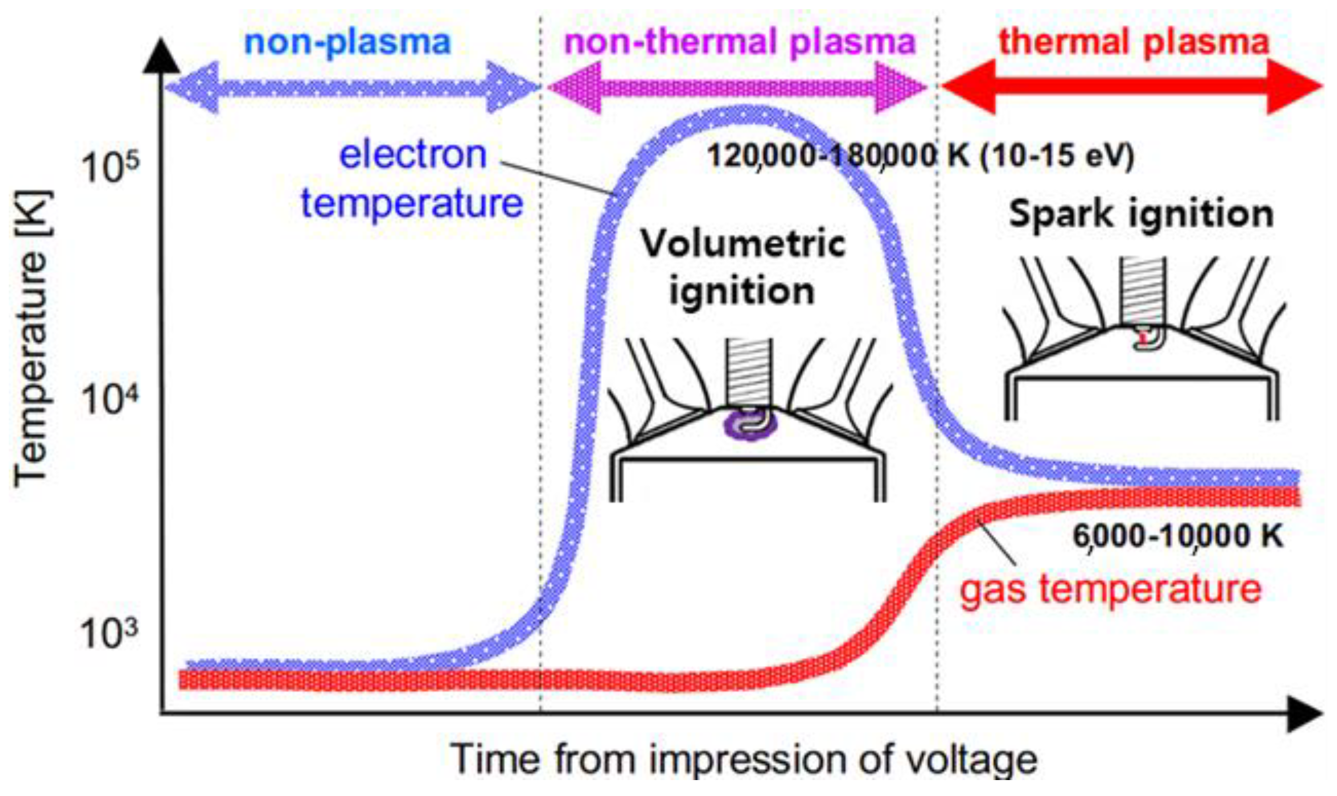
Plasma refers to a gaseous state that is separated into negatively charged electrons and positively charged ions at very high temperatures [13]. This can be generated through electrical methods such as a direct current, very high frequency, and an electron beam. The state of matter is generally divided into three categories: solid, liquid, and gas. When high energy is applied in the gaseous state, it can be separated into free electrons and atomic nuclei and finally become a plasma state, so it is also called the fourth state of matter. Since plasma contains electrons with high energy levels and highly reactive active species, it can cause the dissociation of reactants, ionization, and excitation of electrons [14]. Therefore, when applied to a combustion system, it enables provision of a significant number of free radicals, ions, and excited molecules that promote chemical reactions. Plasma can be classified into thermal plasma and non-thermal plasma according to the temperature of electrons, ions, and molecules. Figure 2 shows the electron and gas temperature ranges in the normal, non-thermal plasma, and thermal plasma states. In a thermal plasma state, sufficient kinetic energy is exchanged between electrons, ions, and molecules to achieve thermal equilibrium. Therefore, about 50% of the energy of the plasma is consumed as heat loss in the electrode or around it [2]. On the other hand, in the case of non-thermal plasma, the temperature of electrons is significantly higher than that of ions and molecules. In this case, the heat loss is low, and the chemical reaction can be promoted by using the high energy level of the electrons. In conventional combustion, a flame kernel is generated at one point and combustion proceeds as the flame expands. However, non-thermal plasma is also called volumetric ignition because several flame kernels are generated and combustion proceeds. Since multiple flame kernels occur and combustion proceeds in a wide volume, the flame propagation speed can be improved. Detailed application examples of each ignition approach are described in Section 2.1 and Section 2.2.

2.1. Thermal Plasma

2.1.1. Plasma Jet Ignition

Plasma jet ignition is a method of realizing a plasma jet by discharging 1–10 J of high energy in a small cavity called a pre-chamber to form a plasma state and then creating a jet through a small nozzle. Ignition energy can be improved via capacitive discharge through a large capacitor. A high voltage discharge caused by the induction ignition coil causes a spark discharge and supplies a large amount of energy to the capacitor causing a crash. The hydrodynamic effect of active species and high-velocity jets forms a high-current plasma ignition source to improve combustion. The previous research on plasma jet ignition was mainly focused on the optimization of combustion, nozzle length, cavity volume, and extension of lean limits.
Yoshida et al. investigated various igniter designs in a constant volume chamber. Their study revealed that the performance of the plasma jet igniter is greatly affected by design factors such as the volume of the cavity and the size of the orifice [16]. As shown in Figure 3, the cavity volume was controlled by changing the diameter and depth, and the size of the nozzle was changed by adjusting the diameter (d1) of the center electrode and the diameter (d2) of the ground electrode. The ejection angle (θ) of the jet was also adjusted. The flame was visualized through the Schlieren method ambient pressure of 0.1 MPa, a temperature of 313 K, and ignition energy of 5 J. Propane was used as a fuel, and the combustion test was carried out under an equivalence ratio of 1.0. As a result of the experiment, it was confirmed that the higher the cavity volume in the plasma jet igniter was, the higher the maximum combustion chamber pressure and the faster flame propagation speed. It was shown that the larger the nozzle area was, the smoother the plasma jet was ejected. As a result of the ejection angle of the plasma ignition, it was confirmed that the case of 90° was advantageous in promoting combustion, similar to the previous study.
In this study, the combustion enhancement ratio and index of combustion were calculated using the following formulas to quantify the effect of a plasma jet on combustion:
Combustion enhancement ratio (Ψ) = 1 − tpl/tcon
(tpl: time duration to reach maximum pressure with plasma igniter, tcon: time duration to reach maximum pressure with conventional igniter);
Index of combustion (Ic) = (Ppl,max/Pcon,max)/(tpl/tcon)
(Pmax: Maximum chamber pressure with plasma igniter, Pcon: Maximum chamber pressure with conventional ignitor).
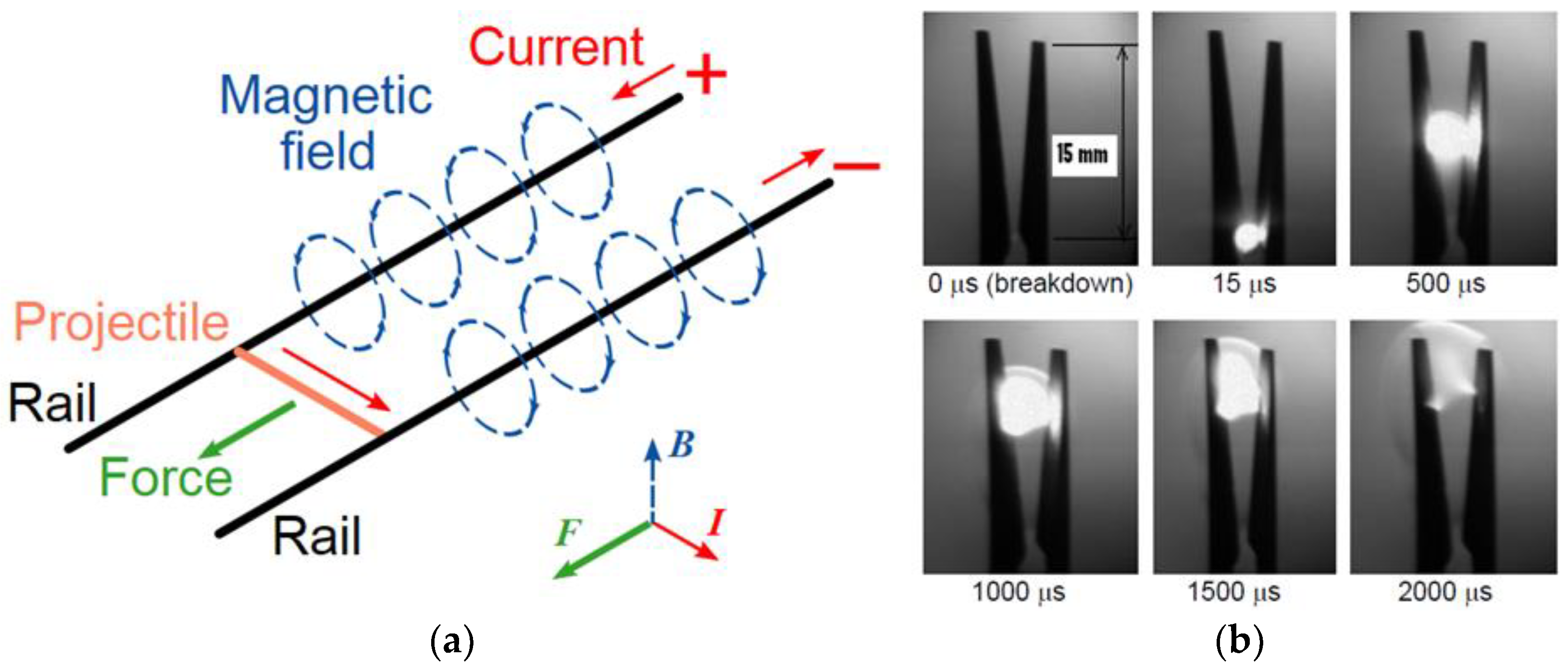
As a result of the analysis, the combustion enhancement ratio increased from a minimum of 0.05 to a maximum of 0.45. The igniter with a plasma jet ejection angle of 90° had a value about twice more extensive than the 45° case. On the other hand, the combustion index increased from a minimum of 1.0 to a maximum of 2.0. Meanwhile, as the plasma jet igniter has problems in terms of heat loss and material durability in the process of burning plasma using a tiny volume cavity and nozzle at high temperature, Gao et al. developed a new igniter that minimized the contact between the thermal plasma and the igniter wall. The igniter used in this study was called a rail plug which operates with the same a principle as a railgun [17]. The ignition occurred by accelerating plasma using the Lorentz force. Figure 4 shows the railgun’s principle and the rail plug’s ignition process. A strong magnetic field is formed between the electrodes when a DC voltage is applied between the positive (+) and negative (−) poles. If Fleming’s left-hand rule is applied, it can be seen that the force acts as shown in the figure.
In the rail plug, an arc discharge is generated using a high energy of 210 V of DC voltage and an ignition period of 1.6 ms, that is, 3 J/shot, accelerated by the Lorentz force and ejected in the form of a jet. This igniter was applied to a four-cylinder 2.2-L natural gas engine, and combustion characteristics were compared with the conventional spark plug [18]. It was confirmed that the rail plug could expand the flammability limit with improved combustion stability. The combustion stability results of available spark plugs and rail plugs at 1200 rpm and full load (WOT; wide open throttle) conditions. The rail plug showed a faster burning rate than conventional spark plugs, showing the potential for knocking reduction. The enhancement of flame propagation was also confirmed in a constant volume chamber test by Hall et al. [19]. As a result of the experiment, a high-flow jet-type flame was generated, and the flame propagation per unit of time was confirmed to be much faster, showing results consistent with previous studies. However, although the developed rail plug was superior in terms of its heat transfer and durability to the plasma jet igniter that has been traditionally studied, the improvements in the combustion stability and flammability limit were not significant.
Kim et al. realized plasma jet ignition by adding an additional electric energy circuit to commercially available ignition coils [20]. Experimental studies were conducted on the relationship between flame thickness and speed between combustion with a conventional spark plug and plasma combustion using a jet-type plug. Propane was used as the fuel, and the initial pressure was 2, 3, and 4 bar in three cases, and the combustion proceeded while changing the condition gradually from 1.0 to 1.9 in 0.1 units from lambda to lean conditions. A high-speed camera was used to visualize the combustion inside the chamber while numerical studies were also conducted through Ansys Fluent software. When combustion was performed using a conventional spark plug, combustion progressed up to lambda 1.6. Moreover, when comparing the flame propagation simultaneously, it was confirmed that the flame thickness and combustion speed were significantly increased, thereby improving the combustion efficiency.
In summary, plasma jet technology can improve combustion performance and extend lean limits, however, it is practically challenging to commercialize due to enormous heat loss and material corrosion as high-temperature plasma directly contacts the igniter. Table 1 summarizes the plasma jet igniter’s development and combustion test results.

2.1.2. Laser Ignition

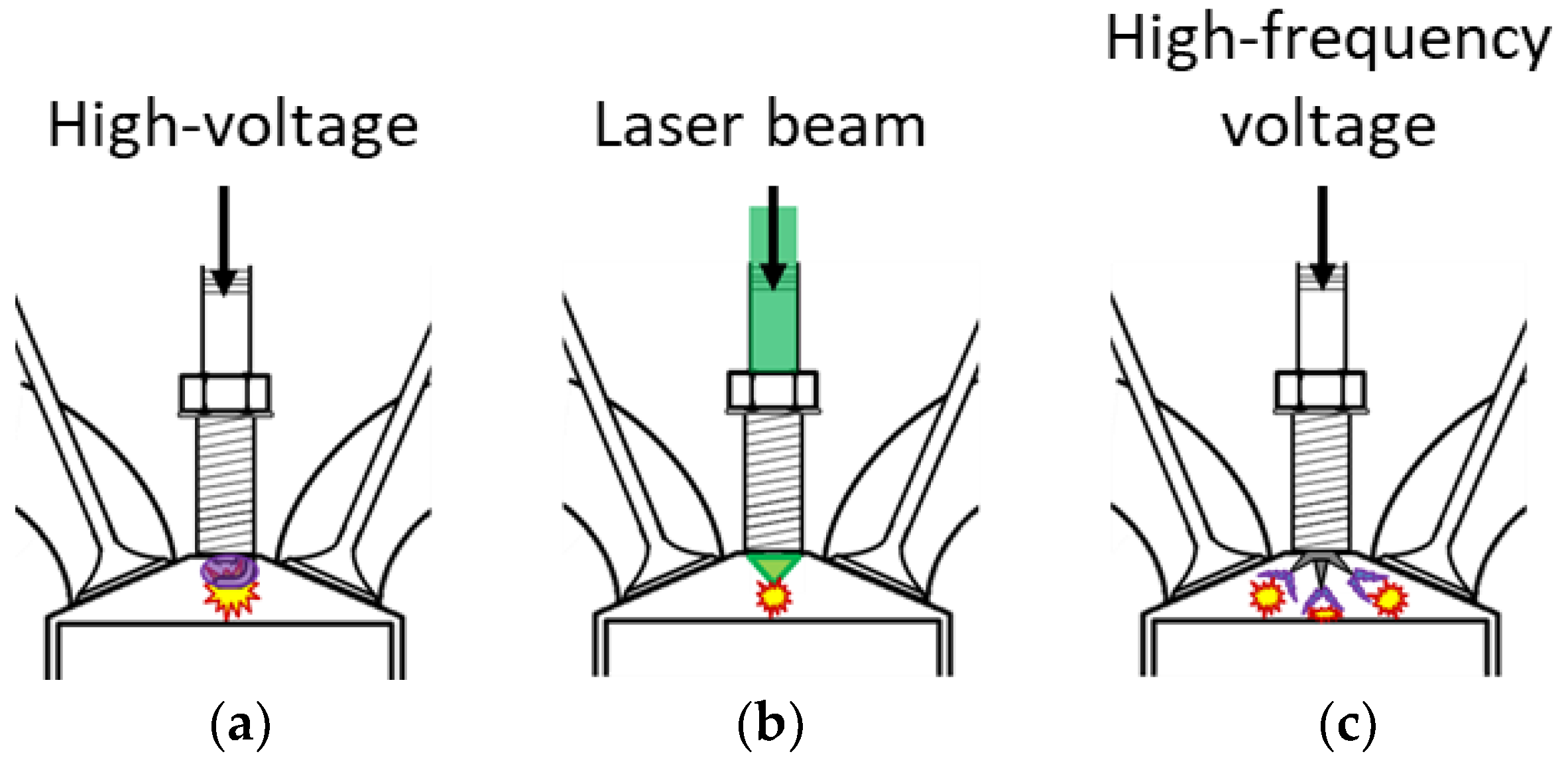
Laser-induced plasma ignition technology refers to a technology in which the laser is focused on the desired point in the combustion chamber through a window to burn by point thermal plasma generated through ionization and dissociation of the mixer. In this technique, a high-power laser source, for example, Nd:YAG is usually used. A laser pulse accumulates tens of millijoules of energy in a short period of time, such as a few nanoseconds. Figure 5 schematically shows the comparison between conventional spark ignition, laser-induced plasma ignition, and multi-point ignition. Unlike conventional spark plugs, this technology has no heat loss because there is no heat transfer medium through electrodes or conduction. Since it has a high degree of freedom in space, combustion can be initiated at a desired time and point in the combustion chamber. Unlike other methods, laser plasma ignition does not have electrodes, so it forms a smooth flame kernel. In addition, it is possible to simultaneously ignite multiple points in the combustion chamber according to the laser beam irradiation method, thereby shortening the combustion period and improving efficiency.
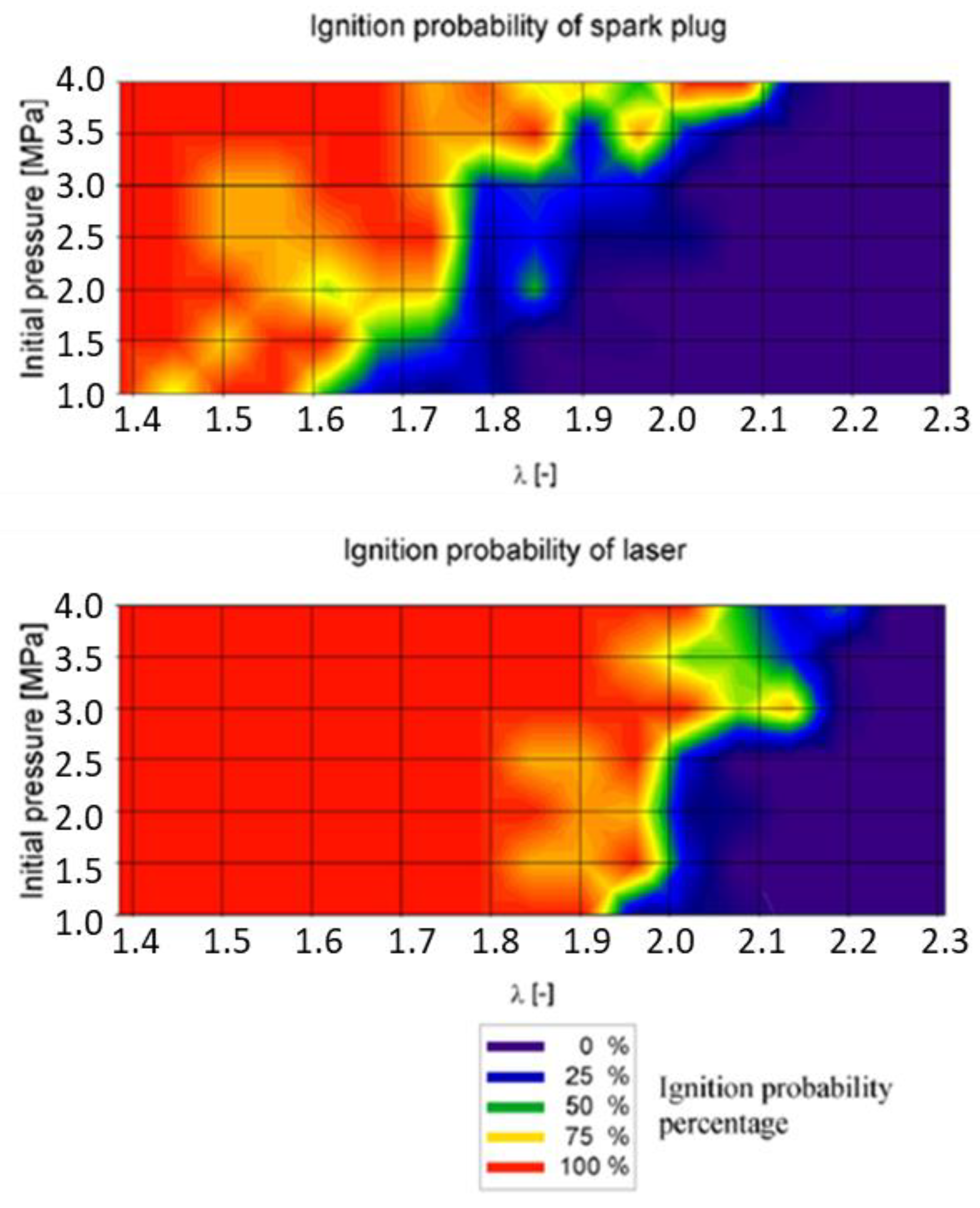
Weinrotter et al. compared the combustion characteristics and flammability limit in a static combustion chamber using a Q-switched Nd:YAG laser and a general spark plug [23]. Methane and air were used as the mixer, and the experiment was conducted at an initial pressure of 4 MPa and an initial temperature of 473 K. As ignition energies, the laser-induced plasma ignition and standard spark plug ignition were 25 mJ and 180 mJ, respectively. As a result of the experiment, it was confirmed that the ignition delay period was reduced by about 20%, and the maximum combustion pressure was higher when the laser-induced plasma ignition technology was used. Laser-induced plasma ignition was also shown to have an excellent performance in combustion stability calculated based on the maximum combustion pressure. In this study, 1,800 repeated combustion experiments were conducted to determine the combustion potential according to the air and fuel mixing ratio. The ignition probability was calculated by distinguishing between normal combustion and abnormal combustion based on the pressure of the static combustion chamber and the amount of carbon monoxide generated in the combustion chamber. Figure 6 indicates the probability of combustion according to the ratio of air and fuel through repeated experiments. As can be seen from the experimental results, when the laser-induced plasma ignition technology is applied, the flammability limit is extended, combustion occurs stably, and low misfire or partial combustion can be expected when applied to an actual engine.
Groß et al. applied a laser-induced plasma igniter to a 0.5 l single-cylinder direct injection gasoline engine and investigated combustion and exhaust characteristics. Nd:YAG was used as the laser source and the ignition energy was changed from 10 mJ to 50 mJ [24]. Before the engine test, the ignition point was matched by irradiating the laser to the location where the plasma channel of the general spark plug was generated through the visualization of the combustion chamber interior. The experiment was performed under two conditions: homogeneous and stratified charge combustion. As a result of examining the combustion characteristics, it was confirmed that the initial combustion speed and stability were improved in the case of laser-induced plasma ignition under the homogeneous combustion condition. As the ignition energy increased, the fluctuation rate of the urban average adequate pressure decreased. However, under the stratified combustion condition, it was found that the combustion stability deteriorated, and a more significant number of hydrocarbons were generated than when a conventional spark plug was applied. It was explained that it was challenging to form the conditions for combustion in the stratified combustion condition, which was sensitive to the equivalence ratio of the ignition point and the speed of the mixer because plasma was generated. This phenomenon was described by Genzale et al. who also confirmed this. In this study, gasoline was directly injected into a static combustion chamber and combustion was realized using a 10 mJ, 8 ns Nd:YAG laser signal [25]. Before applying laser-induced plasma ignition, the distribution of liquid and gaseous phases was found by performing a spray experiment in a static combustion chamber. The laser was applied at a point of 1.0 by calculating the equivalence ratio in the spray. As a result of the experiment, it was possible to control the ignition timing more precisely than a general spark plug. However, even at the same point, the equivalence ratio changed at every injection, so it was necessary to find an optimized ignition location and optimized timing.
Tsunekane et al. investigated the flame propagation characteristics of laser-induced plasma ignition and spark plugs using the Schlieren method in a static combustion chamber [26]. Q-switched Nd:YAG was used as the laser source and the ignition energy was 2.7 mJ. The power intensity at the focal length of the laser was calculated to be 5 TW/cm3. As a result of conducting a combustion experiment under the stoichiometric air–fuel ratio of propane and air, it was confirmed that the conventional spark plug was formed at an air–fuel ratio of 15.7. In contrast, in the case of laser-induced plasma ignition, the ignition was enabled up to an air–fuel ratio of 17.2. In addition, it was confirmed that the flame front propagated faster even with a 1/3 lower level of ignition energy than a general spark plug.
Pavel et al. analyzed combustion characteristics and emissions through the experiment of a laser-induced plasma ignition engine constructed with an Nd:YAG/Cr4:YAG under the condition of the 2000 rpm—2 bar condition [27]. Each laser spark plug was supplied with an energy of 4 mJ, and the experiment was conducted under two conditions of lambda 1 and 1.25. In the condition of lambda 1, the engine brake power increased by 7.9% compared to the case of conventional spark ignition when the laser ignition was applied and increased by 29% in the condition of lambda 1.25. In the case of fuel consumption, it decreased by 7.4% under the lambda 1 condition and 21% under the lambda 1.25 condition, indicating that the laser ignition was adequate under the lean condition. In terms of exhaust, when igniting using laser-induced plasma, HC and CO decreased overall compared to the standard spark ignition, but nitrogen oxide (NOx) increased.
Kumar et al. experimented with a condition where the mixture ratio of n-butane and air was ϕ = 0.7 in a constant volume combustion chamber (CVCC) using laser-induced plasma ignition. The experiment was conducted while changing the pulse width and pulse repetition frequency as parameters. When using an Nd:YAG, the calculated energy was about 14.3 mJ. Experimental results showed that the ignition success rate increased and the ignition delay time decreased as the pulse width or pulse repetition frequency increased. It has also been shown that combustion can be accelerated by increasing the plasma temperature and active radicals [28].
Pastor et al. (2017) injected diesel through a Bosch common rail injector into a combustion chamber surrounded by a quartz window and performed image analysis using the Schlieren method [29]. The combustion chamber is specially designed to reduce spray wall impact. Plasma was induced via an Nd:YAG operating at 800 mJ energy. In the 50 Mpa injection pressure condition, the equivalence ratio locally reached 12, and the ignition success rate was 100%. In the case of conventional auto ignition, the ignition delay is about 2600 us, whereas when laser-induced plasma combustion is used, the ignition delay is reduced to about 1000~1500 us. It has a more stable combustion than the spontaneous combustion of a diesel engine. It was confirmed that moving the laser-inducted plasma ignition along the spray axis directly affects the ignition delay.
Overall, laser-induced plasma ignition technology does not have any concerns about heat loss or corrosion due to the igniter itself, which has been a problem in thermal plasma igniters, but has disadvantages in that the cost and complexity increases when configuring the system, and device cooling is difficult during continuous operation. In addition, when applied to an actual engine, the ignition characteristics change significantly depending on atmospheric conditions, so optimization of the ignition timing or point is required. Therefore, it is expected to be used in fields such as fuel reforming in/out of a combustion chamber rather than as a means of igniting. Table 2 shows the summary of the development and combustion experiments of the laser-induced plasma igniter.

2.2. Non-Thermal Plasma

2.2.1. Corona Ignition

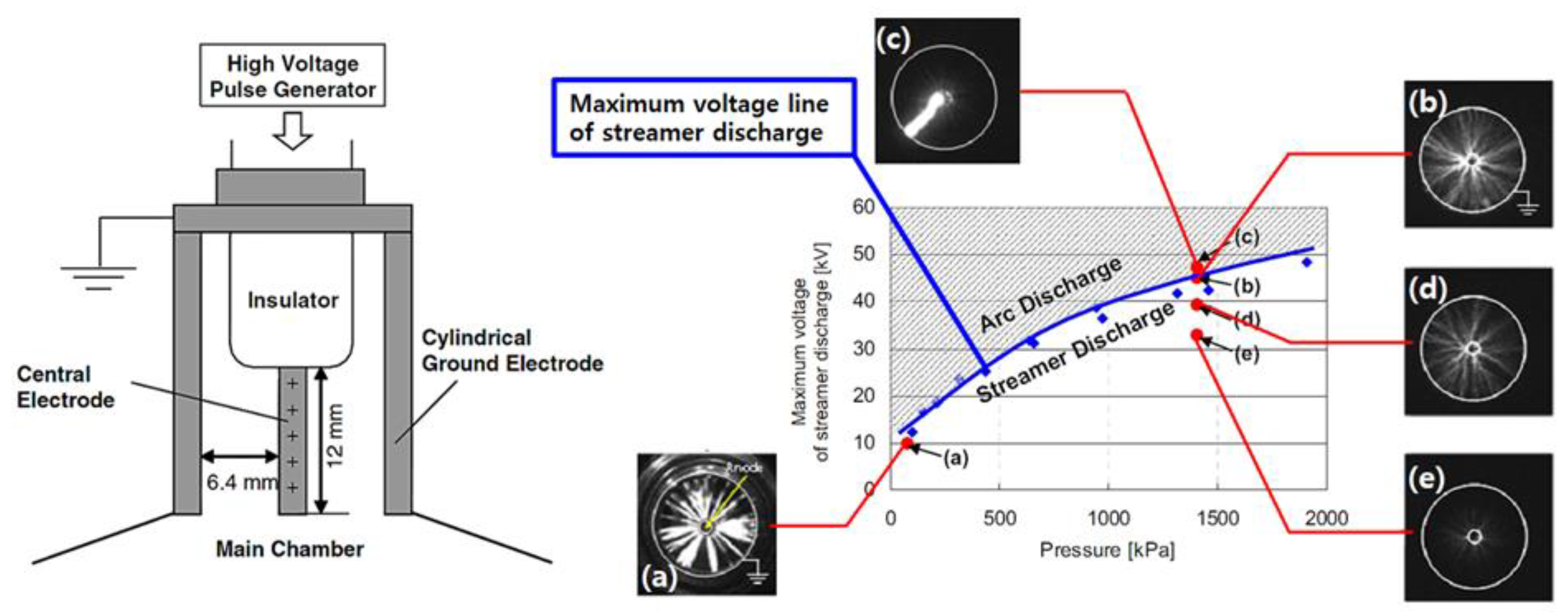
Corona discharge is a technology that uses a chemical reaction with free radicals generated by applying a high voltage to a small-diameter conductor metal and then ionizing the surrounding gas into plasma. The electrode structure uses a small-diameter discharge wire, needle, or sharply processed metal electrode to facilitate the discharge by generating a strong electric field. Corona igniters have multiple electrodes, so multiple ignition flame kernels can be formed during discharge. Utilizing nanosecond-pulsed plasma can improve the corona’s power characteristics while retaining its ability to generate large amounts of radicals. Both direct current and alternating current can be used as the supply power. Shiraishi et al. developed a plasma igniter composed of a thin pin-shaped center electrode and a cylindrical ground electrode, applied it to an engine, and performed a comparative experiment with a general spark plug [32,33]. A streamer discharge was generated by applying a DC voltage of 10–40 kV, a range in which arc discharge does not occur, through a basic discharge test between the two electrodes. Figure 7 shows the discharge shape according to atmospheric pressure and voltage.
In arc discharge, bright and thick plasma channels form locally inside the igniter, whereas in the case of streamer discharge, it can be seen that thin and many plasma channels extend to the ground electrode. These channels are also called volumetric discharges because they do not occur only in one section but exist entirely inside the cylindrical igniter. The electric field inside the cylindrical igniter can be expressed as the following equation:
E l e c t r i c   f i e l d   s t r e n g t h   E ( r ) = ( V r · l n ( r 2 r 1 ) )
( V : applied voltage, r 1 : radius of central electrode, r 2 : distance between igniter center and ground electrode).
Therefore, it can be seen that the luminosity of the streamer discharge near the center electrode is high because the electric field becomes more extensive as the distance from the surface of the electrode increases. In addition, it can be seen that the lower the applied voltage, the smaller the generated electric field is, so the luminous intensity lowers. The basic experiment on the igniter confirmed that the applied voltage for the discharge increased as the atmospheric pressure increased, and the streamer discharge was realized by applying a voltage lower than the boundary voltage between the arc discharge and the streamer discharge. In a single-cylinder port injection gasoline engine, combustion characteristics were examined based on the internal pressure of the combustion chamber, and flame propagation characteristics were compared through downward flame visualization in a visualization engine having the same structure [32]. Ignition energies were 80 mJ and 60 mJ for general spark plugs and streamer dischargers, respectively. As a result of the experiment, when the streamer discharger was used, the ignition delay was shortened, and the maximum heat dissipation rate was increased. In the flame visualization results, it was possible to confirm the fast flame propagation speed and the large flame luminance. It was explained that the reason for such a result was that the chemical reaction proceeded by the collision of the electrons accelerated by the large electric field between the center electrode and the ground electrode with the fuel molecules had a faster reaction rate than the reaction that was caused by a high temperature and high pressure. While the coefficient of variation (COV) of the indicated mean effective pressure (IMEP) of the streamer discharge was maintained at 5% or less even under the lean condition, demonstrating improved combustion stability.
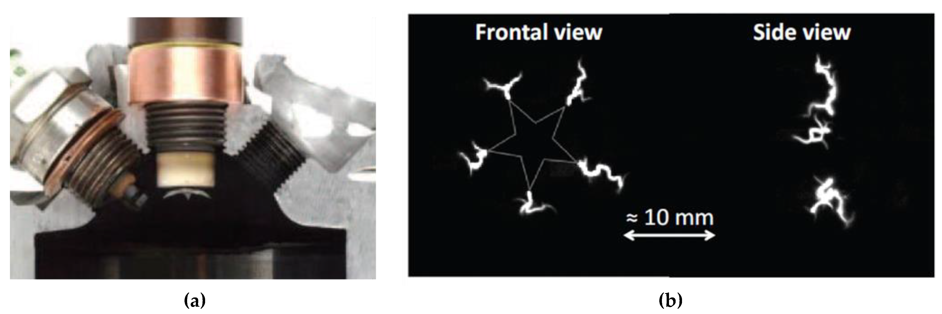
Hampe et al. applied a high-frequency corona discharge igniter with five sharp peaks developed by Borg Warner of Germany to a 0.1 l class 2-stroke engine and examined combustion and exhaust characteristics [34]. Figure 8 shows the igniter and discharge shape. The igniter applies an alternating voltage having a frequency of 6 kV and 4.98 MHz to ignite through the corona discharge generated by a strong electric field at the tip of the electrode.
As a result of the primary combustion characteristics, it was confirmed that the maximum pressure in the combustion chamber increased, and the combustion period and ignition point decreased. In terms of exhaust emissions, there was no significant difference in nitrogen oxide emissions. However, it was confirmed that the hydrocarbons and carbon monoxide were reduced based on the improved combustion speed and combustion efficiency when the corona discharge was applied. After the engine test, it was reported that there was no thermal damage or destruction in the igniter, so it proved that this improved the thermal damage characteristics compared to the thermal plasma approach.
Hampe et al. examined combustion and flame characteristics by applying a corona igniter with one and five electrodes, respectively, to a 0.5 l class single-cylinder direct injection gasoline engine and a static combustion chamber to investigate the combustion characteristics according to the number of igniter electrodes [34,35]. As a result, the combustible lambda of the available spark plug was formed around 1.3, while the two corona igniters were extended to 1.6, and it was confirmed that the igniter with more electrodes among the two igniters had a faster combustion rate. As a result of measuring the volume of the corona generated through the basic ignition experiment in the static combustion chamber, the corona generated in the igniter with 5 electrodes was about twice as large. Furthermore, when examining the occurrence of the corona discharge according to atmospheric pressure, when there was one electrode, it was successful even under an atmospheric pressure of 6 MPa. However, when there were 5 electrodes, the atmospheric pressure was limited to about 2 MPa. However, when examining the conditions inside the combustion chamber of an actual gasoline engine, it was determined that an igniter with five electrodes would be advantageous in terms of the combustion or exhaust because the ignition occurs at an atmospheric pressure of 2 MPa or less.
Mariani et al. investigated the combustion and exhaust characteristics of a 1.6 l class direct injection multi-cylinder gasoline engine using an igniter with five electrodes among the systems used in the previous study [36]. The experiment was carried out under the conditions of an engine speed 1400 rpm, indicated mean effective pressure of 0.4–0.1 MPa, intake air dilution with nitrogen from 0–30%, and an equivalence ratio 0.6–1.0. As a result, it was confirmed that the flammability limit was formed at an equivalence ratio of 0.6 when the corona igniter was applied, while the general spark plug was only 0.75, so the flammability limit was extended. In addition, it was shown that the combustion stability was improved by maintaining the variation rate of the indicated mean effective pressure below 5%, even under such a lean mixture. Due to the excellent combustion characteristics of the corona igniter, the fuel consumption rate was reduced by up to 5%, and it was confirmed that the hydrocarbon and carbon monoxide emissions were also reduced. However, it was explained that the nitrogen oxide increased by about 16% on average because the temperature inside the combustion chamber increased more rapidly. After all, the maximum value of the combustion chamber pressure and the pressure increase rate during corona discharge were significant.
Pineda et al. conducted an experiment on a 0.5 l single-cylinder gasoline engine [37]. They investigated the characteristics of the combustion and exhaust gases (HC, CO, NOx) by installing a corona ignitor adjacent to the injector. As a result of the experiment, when the radio frequency corona discharge ignition system was applied in the naturally aspirated condition, the COV IMEP was slightly reduced compared to the combustion of a general spark plug. When the same level of fuel was consumed, the HC and CO levels were similar, and the engine operated at a higher EGR condition with fewer NOx emissions. When the radio frequency corona discharge ignition was applied in the boost condition, less fuel was consumed when producing the same output as compared to a general spark plug combustion, and the exhaust gas was significantly reduced.
Zembi et al. experimented with a 500 cc single-cylinder visualization engine using corona ignition and analyzed the combustion process through the Reynolds-Averaged Navier-Stokes computational fluid dynamics (CFD) simulation [38]. The results were analyzed while changing lambda as an experimental variable. The presence of active radicals did not affect the spark’s combustion rate. On the other hand, the atomic oxygen affected accelerating the nuclear and initial flame propagation caused by the corona ignition. As a result of the simulation, when RF corona ignition was applied, a large amount of mixture related to the discharge increased, which took about 4 times faster to reach 1% Mass Fraction Burned.
Poggiani et al. conducted a study on the combustion characteristics under lean combustion conditions when using a corona plasma spark in a 500 cc optical access PFI engine. The standard European market gasoline fuel RON = 95 was used. When a corona plasma spark was used under the 1000 rpm experimental conditions, the lean burn limit was extended by about 0.25 from lambda 1.4 to 1.65 compared to conventional spark plugs. As a result of the average of 100 cycles, the IMEP max was about 1 bar lower. The NOx was emitted on average by 200 ppm more. The time for the mass fraction burned (MFB) to reach 1% was 4 times faster, and it was 2 times faster to reach 5%. Through this, the effect of a large capacity of corona ignition discharge on initial combustion was confirmed [39].
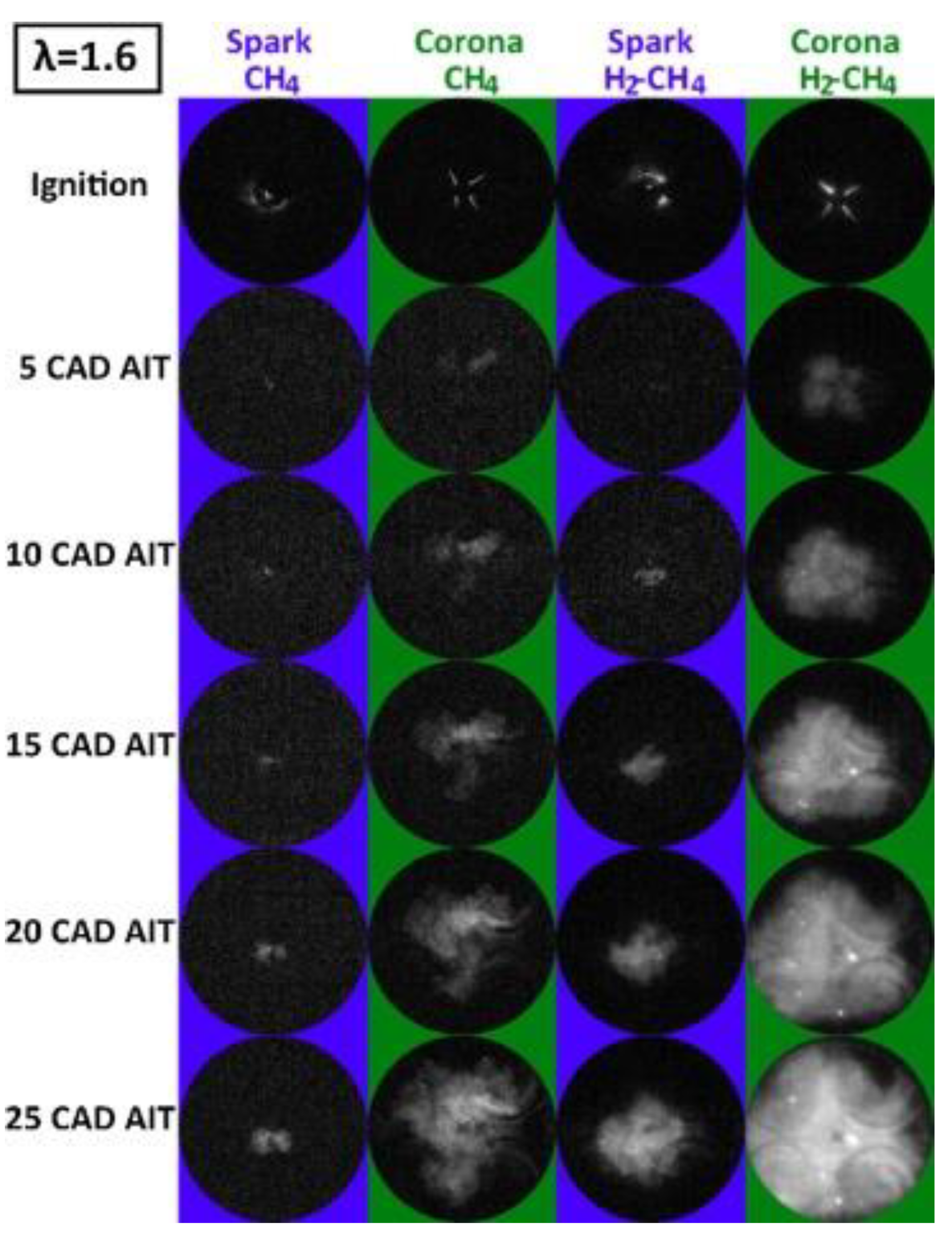
Cruccolini et al. compared combustion through a conventional spark plug and a corona plasma igniter through a 500 cc single-cylinder optical engine in a four-cylinder engine. The fuels were tested for CH4 and H2 (35%)-CH4 (65%) mixtures, rpm was fixed at 1000 rpm, and lambda was changed from 1.0 to 2.0 and compared under the same experimental conditions. The energy delivered at the optical engine test points ranged from 2 to 5 mJ for conventional spark plugs and 10 to 20 mJ for corona igniters. As a result of the experiment, when using the corona plasma igniter, CA0-5, which represents the initial combustion rate, was about 10 degrees lower than that of the existing spark plug based on the crank angle. Through this, it can be seen that the combustion rate was improved. For the fuel CH4, H2-CH4, the respective lean limits were approximately lambda 1.5 and 1.9 for conventional spark plugs, and approximately lambda 1.65 and 2.0 for corona plasma igniters. Therefore, the lean limit was improved when using a corona plasma igniter [40]. The comparison of flame evolution in the combustion chamber is shown in Figure 9.
Overall, the ignition technology using corona discharge is the closest technology to commercialization because it can implement an ignition system that is relatively simple and has little risk of corrosion. Advanced corona discharge igniters have completed the system development and are known to be preparing for commercialization through engine durability, system modification, and supplementation. However, research on this is necessary since more needs to be clarified on the principle and process of promoting a chemical reaction using a non-thermal plasma. Table 3 summarizes the corona discharge igniter’s development and combustion test results.

2.2.2. Microwave-Assisted Ignition

Microwave-assisted plasma ignition is a technology that uses a high-frequency fluctuating electric field to heat free electrons in a flame to increase the energy level of oxygen or hydroxide ions to promote combustion. Conventional spark plugs generate ignition by discharging the ignition coil, but this technology emits microwaves before ignition occurs. Then, the energy level of the surrounding fuel molecules increases, and when ignition occurs, the chemical reaction is accelerated, resulting in smooth combustion. Ju et al. studied the reaction rate according to the energy level of hydrocarbon fuels, which is a state in which fuel molecules are in an excited state, that is, in Equations (5) and (6) in the following equations, in a steady state. It was confirmed that the reaction rate was about 2000 times faster than that of Equation (4) [42].
C H ( X 2 Π ) + O H C O 2 + e
C H ( A 2 Δ ) + O H C O 2 + e
C H ( B 2   ) + O H C O 2 + e  
Groff et al. examined the behavior of floating flames by placing a burner using ethylene, methane, and propane fuel, where the electric field is the largest in a static combustion chamber designed in the TM010 mode [43]. A magnetron system generated microwaves with a variable frequency of 0.8–2.5 GHz of the 150 W class. Using a high-speed camera, the location of the flame was determined, the speed was calculated, and the shape was observed. As a result of the experiment, it was confirmed that when the microwave was applied, a deflection of the shape was generated, and the flame speed was increased relative to that of a general flame. Although there was a difference in the amount of increase in the flame speed depending on the fuel, it was confirmed that it increased from a minimum of 4.5% to a maximum of 6.4%. They explained that the reason for this result was that the rapidly fluctuating electric field increased the rotational energy of free electrons in the flame, and the chemical reaction was promoted in the process of transferring energy via collision with other molecules, that is, fuel or oxygen. Maclatchy et al. also examined propane flames using a 2.5 GHz magnetron of a 500 W class. When microwaves were applied, there was no significant effect at the equivalence ratio of 0.8–1.3 [44]. It was confirmed that the flame speed increased by about 2%. This study measured the temperature of electrons in plasma using a Langmuir probe. It was confirmed that the temperature increased by 55% compared to the general case when microwaves were applied to the flame surface.
Stockman et al. studied the effect of microwaves on the flame by locating the methane levitation flame where the electric field in the waveguide is most robust using a 1.3 kW class magnetron at 2.45 GHz and a waveguide with a TE010 mode [45]. In this study, the flame temperature, velocity, and hydroxyl concentration were measured using filtered Rayleigh scattering (FRS), particle image velocimetry (PIV), and planar laser-induced fluorescence (PLIF). As a result of the experiment, it was confirmed that the flame speed increased based on the fact that the location of the flame moved closer to the burner when microwaves were applied in the form of a continuous wave. There was a difference in the amount that it increased depending on the equivalence ratio condition, but it was found to have risen from a minimum of 6% to a maximum of 20%. Moreover, although the shape of the flame surface was flat in a normal flame, the deflection was observed when microwaves were applied. As a result of measuring the hydroxyl concentration at the flame surface, the maximum value increased by about 6.5% when microwaves were applied, and it was found that the decreasing trend was small along the flame axis. Figure 10 shows the results of PIV and PLIF when the normal injury flame and microwave are applied.
As a result of measuring the flame temperature, it was confirmed that it increased from a minimum of 100 degrees Celsius to a maximum of 200 degrees Celsius when microwaves were applied. Furthermore, as a result of calculating the amount of energy absorbed by the flame front based on the temperature rise result, it was found to be about 20–40 W, which was 13–26% of the 150 W inputted.
Imagineering is known as the first company to manufacture microwave-assisted igniters and apply them to internal combustion engines. Ikeda et al. developed a microwave-assisted plasma ignition system by modifying a 2.45 GHz, 700 W magnetron installed in a microwave oven [46]. The structure of the system is shown in Figure 11.
The system can be divided into entire subdivisions. First, the control system that transmits a signal to the magnetron generates a signal going to the spark plug and the magnetron. Since the applied time and period of the spark plug signal and the magnetron signal compared to the reference signal can be adjusted respectively, the signal time and period can be manipulated variables in the experiment. The second is the microwave transmitter. In this part, a microwave is generated using a magnetron and injected into a spark plug through a waveguide, a coaxial cable, and a stub tuner. The waveguide is mainly used in the TM010 mode and has the characteristic that the electric field is generated at the maximum along the central axis of the waveguide. Finally, the spark plug that causes the ignition. There is a method of propagating the transmitted microwave through a separate antenna or a center electrode. The former does not require a separate electronic circuit because there is a channel to which the DC voltage and microwaves are applied, but an antenna is required. They first manufactured an igniter using an antenna in the research and development stage. When an antenna was installed in the place of the pressure sensor-type spark plug and an ignition test was conducted, the amount of hydroxyl radical increased about 300 times when the microwaves were applied. It was confirmed that the possibility of a microwave-assisted igniter was identified. After that, they applied it to a single-cylinder gasoline engine and examined the combustion and exhaust characteristics. The experiment was conducted at an average city effective pressure of 0.275 MPa with an engine speed of 2000 rpm. As a result of the experiment, in the case of a normal spark, the combustion stability rapidly decreased at the point where the air–fuel ratio was about 19.3, whereas, in the case of applying the microwave-assisted igniter, the fluctuation rate of the urban average effective pressure could be maintained below 5% even in the case of 24.1. According to the extended flammability limit, it was possible to realize lean combustion, and it was possible to improve fuel efficiency by up to 5%. In exhaust emissions, it was confirmed that carbon monoxide decreased, but nitrogen oxides slightly increased.
Wolk et al. studied the flame propagation characteristics according to the application of microwave-assisted igniters [47]. In this study, the shape and propagation speed of the flame were investigated through flame visualization using the Schlieren method in a static combustion chamber with the same 2.45 GHz, 500 W magnetron system as in the previous study. Methane was used as the fuel, and ignition tests were performed at an initial pressure of 0.1–0.7 MPa and an initial temperature of 300 K. As a result of the experiment, when a general spark plug and a microwave auxiliary igniter were applied, the flame propagation speed had a maximum value around 1.0 in the equivalence ratio. It was shown that flame propagation was accelerated as the flame rise time was reduced. In addition, the lean/rich flammability limit was extended regardless of the initial pressure. Figure 12 shows the flame propagation according to the initial pressure and the size of the flame core.
As can be seen in the figure, when the initial pressure is low, it can be seen that there is a significant difference between the case where microwaves are applied and the growth of the flame core generated from the general spark plug, whereas the higher the initial pressure is, the difference between the two igniters in terms of the shape and size of the flame core can be seen to decrease. This is because the energy of the average electron is proportional to the size of the reduced electric field, that is, E/N. The variable E stands for the magnitude of the electric field, and N stands for the number density (number of particles per unit volume). When the initial pressure is high, the number of particles per unit volume is large, so the denominator increases, and the average energy of the electrons decreases. To express this physically, it can be explained that the reaction could not be effectively improved because the mean free path of the electrons was shortened as the atmospheric pressure increased. It did not receive sufficient acceleration and lost energy by colliding with surrounding molecules. In accordance with this effect, it was confirmed that the effect of the microwave-assisted igniter on the flame development/growth time decreased as the initial atmospheric pressure increased.
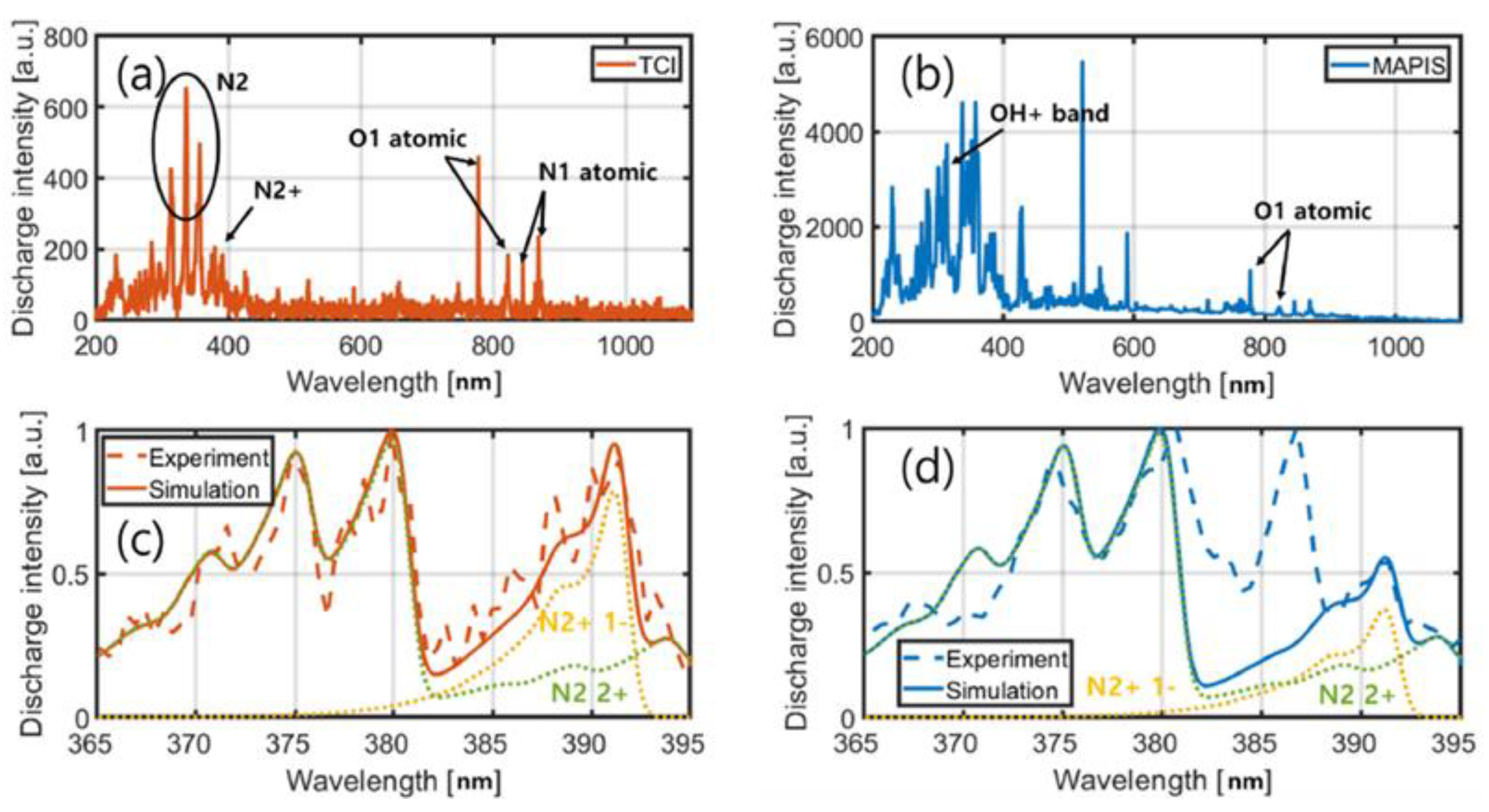
Hwang et al. studied the laminar flame development when they applied microwave-assisted plasma ignition [48]. The experiment was conducted with a 1.4 L CVCC 2.45 GHz magnetron (700 W) system. Compared with the existing spark plug, the microwave-assisted plasma extended the lean limit from the equivalence ratio of 0.6 to 0.5, and the flame propagation speed increased by about 20%. As the mixture was richer and the initial pressure was higher, the effect of improving the combustion flame propagation rate decreased. They extended their study by applying the system in a single cylinder engine system [49]. Pressure, combustion stability, and fuel consumption were comparatively analyzed in a single-cylinder engine test. As a result of imaging the hydroxyl (OH) radicals, it was confirmed that a faster chemical reaction occurred when microwaves were applied. As a result of the single-cylinder experiment, the lambda was extended to 1.55. Microwave-assisted plasma improved fuel efficiency by 6% compared to the existing spark system and increased the pressure peak and heat release rate. Hwang et al. also analyzed the flame properties in the same experimental equipment system through optical emission spectroscopy (OES) and high-speed imaging [50]. As a result, when microwave-assisted plasma was applied, the electron temperature was increased by 5,000 K compared to when only the conventional spark was operated as shown in Figure 13. It was confirmed that the flame propagation was improved by increasing the reactive radicals on the flame surface due to the microwave emission. Moreover, as a result of exhaust gas analysis, CO emission decreased, but NOx emission increased due to an increase in the cylinder internal temperature.
Zhang et al. tested the ignition performance of microwave-assisted ignition (MAI) with a spherical flame premixed with CH4 and air after CO2 dilution to analyze the applicability of MAI under EGR conditions [51]. The experiment was conducted in a 1.6 L static chamber while changing the CO2 dilution ratio to 0–20% and the equivalence ratio to 0.5 to 1.0. At an equivalence ratio of 1.0, the CO2 dilution limit is 8% in the normal SI mode and extends to 20% in the MAI mode. At an 8% dilution of CO2, the lean limit was extended from 0.7 to 0.6. As the intensity of microwaves increased, the time window tended to increase, and as the CO2 dilution ratio increased, the time window tended to decrease. A single microwave pulse of 1 kHz induces a more intense plasma jet and significantly affects the ignition success rate. Therefore, the performance of MAI is improved by increasing the intensity of the microwave to control the plasma jet direction when the CO2 dilution ratio is high.
Wu et al. conducted a study on the effect of the microwave delay time and pulse waveform on ignition and energy coupling enhancement. Experiments were conducted inside the CVCC to maintain a constant equivalence ratio of the methane–air mixture. The pulse width of the microwave was changed from 80 to 200 μs and the energy was adjusted from 400 to 1000 W. Using a fixed incident energy results in a higher power and shorter pulse width waveforms, increasing the ignition and coupling energies. The increase in the ignition energy is directly related to the binding energy. It is recommended to delay the microwave emission by 0.1–0.3 ms for optimal energy coupling [52].
In summary, the ignition technology using a microwave is a technology that can reduce corrosion of the igniter and improve combustion by using non-thermal plasma, which has a lower temperature than the thermal plasma and has the potential to be commercialized at a relatively low price. In addition, although basic combustion experiments have been sufficiently performed, the cases applied to internal combustion engines are extremely rare. It can be said that this is a technology that requires optimization in terms of the shape of the microwave delivery system and spark plug. Table 4 summarizes the experimental results for the microwave-assisted combustion.

3. Other Ignition Systems

In the previous chapter, plasma-assisted combustion is primarily divided into thermal and non-thermal plasma, and is further subdivided according to the assist method. Moreover, it was found that using various types of plasma ignition can amplify the ignition energy and promote combustion. In this chapter, we will introduce plasma and recent novel studies related to ignition and combustion.

3.1. Multi-Spark Ignition

The formation of the initial flame kernel is critical as it affects the combustion and flame propagation process. In addition, multi-spark ignition uses multiple sparks to burn differently than the existing engine that uses one spark plug. Therefore, a high ignition energy is expected to be delivered in the initial stage compared to conventional engine combustion, and stable combustion is possible.
Feng et al. performed a simultaneous electro-optical diagnostic analysis using the Schlieren method on the combustion characteristics when multiple plasmas were installed in a scramjet combustor [58]. A comparison of the combustion with single and multi-channel gliding arcs was analyzed. Compared to the ignition with a single-channel arc, when ignited with a multi-channel arc, multiple flame kernels are simultaneously generated by multiple sparks, so the probability of the initial flame formation is high, and the initial flame area is wide. Ignition time was reduced by 61%, and flame propagation time was reduced by 48%. Based on this analysis, the effect of the multi-channel gliding arc plasma application on supersonic combustion was confirmed. Lin et al. proposed plasma-assisted ignition using a multi-channel spark discharge to improve the ignition of lean burn combustors at low pressures [59]. The firing of single-channel spark discharges and concentrated and distributed multi-channel spark discharges in the combustion chamber of a stainless steel cylindrical pressure vessel with an inner diameter of 5 cm were compared. The effects of different equivalence ratios and pressures in propane/air mixtures were analyzed. The ignition of the lean propane/air mixture at a low pressure was difficult for a single-channel spark discharge. Although the flame initiation time was reduced by accelerating the propagation of the multi-channel spark discharge (MSD) ignition to the flame, it did not significantly change the subsequent flame propagation. Although the distributed MSD had a larger ignition kernel than the concentrated MSD, the ignition performance was lower. In MSD design, they concluded that kernel nesting is a more desirable method. Zhao et al. conducted research on a new ignition system using multiple sparks. In this study, the ignition characteristics of a single spark plug and spark plugs separated by three spaces were compared while maintaining the same ignition energy. In CVCC, the n-pentane/air mixture was tested under conditions of an equivalence ratio of 0.6 to 0.8, and the distance between three multiple spark channels was adjusted from 1 to 2.5 mm. The experiment was repeated 10 times for each condition. Applying the new multi-channel spark plugs at discharge formed a larger ignition kernel than a single-channel and extended the lean ignition limit. The shorter the distance was between the three multiple spark channels, the higher the ignition probability was [60].

3.2. Pre-Chamber Ignition

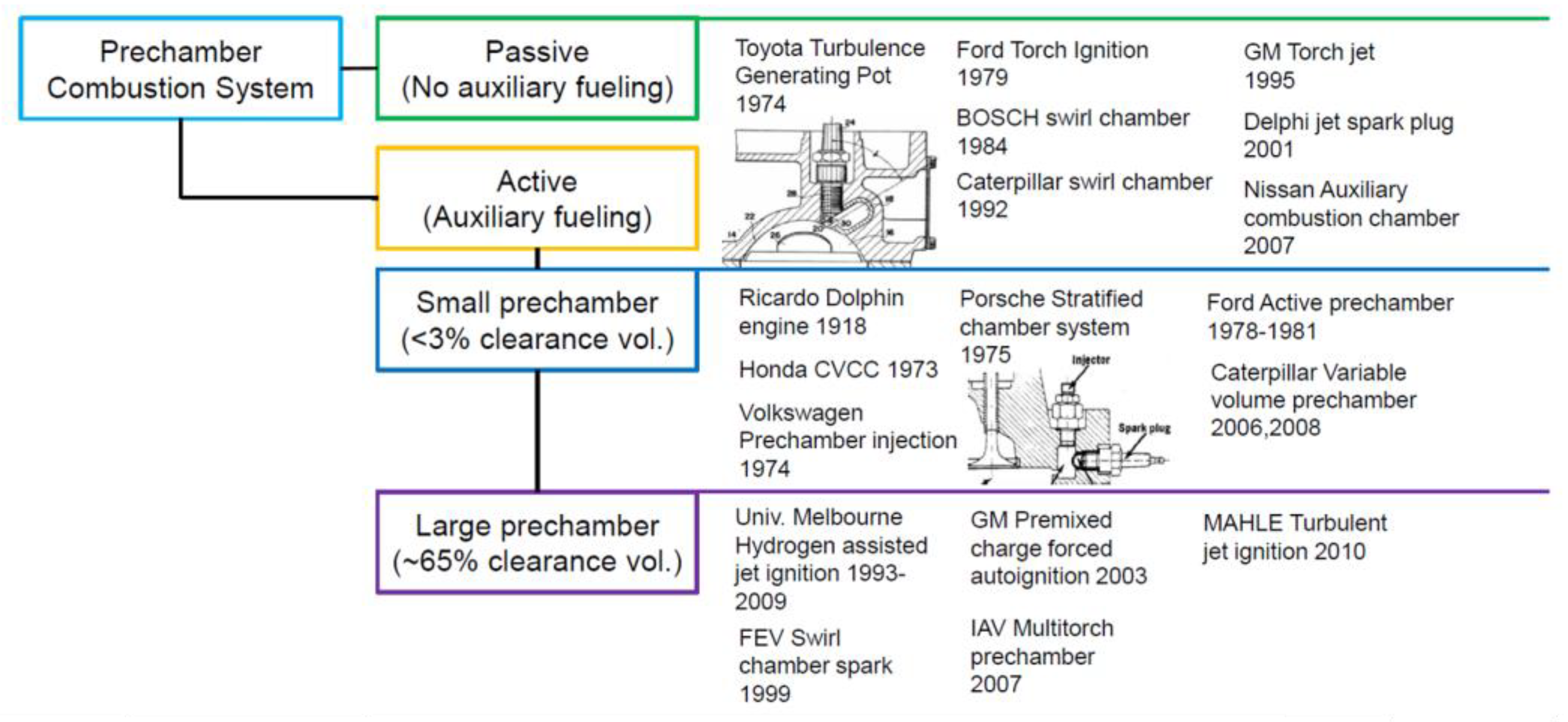
In a general engine, fuel and air are mixed in one main combustion chamber and combustion proceeds. A pre-chamber is a small chamber containing a spark plug. Ignition starts, and the burned flame spreads to the main chamber through the jet nozzle. This has the advantage of shortening the combustion time, reducing knock, and realizing lean burn. Pre-chamber ignition is divided into active and passive according to the type of configuration. Passive systems contain only one spark plug in the pre-chamber. The active system has a spark plug in the pre-chamber and a second small injector for auxiliary fuel injection. In the passive system, the mixture enters the pre-combustion chamber during the compression stroke, and when the spark plug is ignited, the flame is propagated to the main chamber. On the other hand, the active system has an injector in the pre-chamber, so a small amount of fuel is injected, ignition occurs, and the flame is propagated to the main chamber. A historic chart of the research and development on the pre-chamber system is shown in Figure 14. At the beginning of the study, research was conducted in the direction of improving the swirl and turbulence through a passive-style pre-chamber shape [61,62,63]. After that, active style research was conducted to form a rich mixer by auxiliary injection into the pre-chamber [64,65], and research was conducted in the direction of gradually increasing the volume of the pre-chamber [66].
Attard et al. analyzed the combustion and exhaust gases with a 2.4 L single-cylinder engine test [68]. When using liquid gasoline as fuel, the lean limit increased to 1.4 for the normal spark plug combustion and 1.9 if the jet ignition was used. When the main combustion chamber injected liquid gasoline, and the pre-chamber injected gaseous propane, the lean limit was increased to 2.07. As the lean limit was increased, NOx decreased to near zero emissions. Maximum thermal efficiency was around 20% for normal flame combustion and up to 41% for jet ignition. Benajes et al. analyzed the effect of adding hydrogen in a passive pre-chamber system through a numerical methodology [69]. Through this method, gasoline and hydrogen were mixed and evaluated under the same dilution conditions as Lambda 1.9. The CFD model was created via the CONVERGE CFD software, with an engine displacement of 404 cm3 and a compression ratio of 13.4:1. Both the pre-chamber and the main chamber burned stably under lean conditions as the lambda was 1.9. Increasing the hydrogen concentration in the mixture showed significant thermodynamic benefits by increasing the speed of the laminar flame and decreasing the flame thickness. However, as the unburned gas temperature increased, NOx increased.

4. Conclusions

Plasma-assisted ignition systems are continuously being researched in various fields such as aviation, gas turbines, engines, and turbulence flames. In this paper, plasma jet ignition and laser ignition, which belong to thermal plasma, and corona ignition and microwave-assisted ignition, which belong to non-thermal plasma, were subdivided according to the plasma ignition assist method, and the studies conducted so far were reviewed. Recent impressive studies other than plasma-assisted ignition were also reviewed. Plasma-assisted ignition has advantages such as increased combustion speed, pressure, and extended flammability limits. Combustion characteristics depend on the electrical pulse characteristics, discharge current method, initial pressure, air–fuel ratio, and fuel composition. However, it has not been extensively validated for the application in current vehicles. Several studies are needed, such those studying the physics of plasma ignition discharge, chemical dynamics, fluid dynamics, and the interaction of high-voltage electric fields. Additionally, the lack of efficient and validated plasma modeling leaves gaps in experimental and numerical studies. In this way, in order to trust a high-performance ignition system such as plasma-assisted ignition, extensive theoretical, experimental, and numerical research will continue to be required.

Author Contributions

Y.H.C. and J.H. made significant contributions to the classification criteria of technology. And participated in revising the intellectual content. All authors have read and agreed to the published version of the manuscript.

Funding

This research received no external funding.

Data Availability Statement

Data sharing not applicable.
No new data were created or analyzed in this study. Data sharing is not applicable to this article.

Conflicts of Interest

The authors declare no conflict of interest.

Abbreviations

BSFC Brake-specific fuel consumption
CFD Computational fluid dynamics
CI Compression ignition
CO2 Carbon dioxide
CO Coefficient of variation
CVCC Constant volume combustion chamber
DISI Direct injection spark ignition
EGR Exhaust gas recirculation
FRS Filtered Rayleigh scattering
HC Hydrocarbons
IC Internal combustion
IMEP Indicated mean effective pressure
MAI Microwave assisted spark ignition
MFB Mass fraction burn
MSD Multi-channel spark discharge
Nd:YAG Neodymium-doped yttrium aluminum garnet
NOX Nitrogen oxide
OES Optical emission spectroscopy
PFI Port fuel injection
PIV Particle image velocimetry
PLIF Planar laser-induced fluorescence
PM Particulate matter
SG Spray-guided
SI Spark ignition
WOTWide open throttle

References

  1. US Environmental Protection Agency (EPA). Available online: https://www.epa.gov/greenvehicles/fast-facts-transportation-greenhouse-gas-emissions (accessed on 14 July 2022).
  2. Heywood, J. Internal Combustion Engine Fundamentals 2E; McGraw-Hill Education: Boston, MA, USA, 2018. [Google Scholar]
  3. Duronio, F.; De Vita, A.; Montanaro, A.; Villante, C. Gasoline Direct Injection Engines–A Review of Latest Technologies and Trends. Part 2. Fuel 2020, 265, 116947. [Google Scholar] [CrossRef]
  4. Oh, H.; Bae, C. Effects of the Injection Timing on Spray and Combustion Characteristics in a Spray-Guided DISI Engine under Lean-Stratified Operation. Fuel 2013, 107, 225–235. [Google Scholar] [CrossRef]
  5. Yu, C.H.; Park, K.W.; Han, S.K.; Kim, W.T. Development of Theta II 2.4L GDI Engine for High Power & Low Emission; SAE Tech. Pap. SAE International: Warrendale, PA, USA, 2009. [Google Scholar]
  6. Zhu, R.; Hu, J.; Bao, X.; He, L.; Zu, L. Effects of Aromatics, Olefins and Distillation Temperatures (T50 & T90) on Particle Mass and Number Emissions from Gasoline Direct Injection (GDI) Vehicles. Energy Policy 2017, 101, 185–193. [Google Scholar] [CrossRef]
  7. Fisher, B.T.; Knothe, G.; Mueller, C.J. Liquid-Phase Penetration under Unsteady in-Cylinder Conditions: Soy-and Cuphea-Derived Biodiesel Fuels versus Conventional Diesel. Energy Fuels 2010, 24, 5163–5180. [Google Scholar] [CrossRef]
  8. Smocha, R.; Vuilleumier, D.; Christison, K.; Loeper, P.; Ketterer, N.; Pickett, L.; Hwang, J.; Kim, N.; Strickland, T. Gasoline Direct Injector Deposits: Impacts of Fouling Mechanism on Composition and Performance. SAE Tech. Pap. 2022, 4, 1413–1430. [Google Scholar] [CrossRef]
  9. Spicher, U.; Magar, M.; Hadler, J. High Pressure Gasoline Direct Injection in Spark Ignition Engines-Efficiency Optimization through Detailed Process Analyses. SAE Int. J. Engines 2016, 9, 2120–2128. [Google Scholar] [CrossRef]
  10. Park, C.; Kim, S.; Kim, H.; Moriyoshi, Y. Stratified Lean Combustion Characteristics of a Spray-Guided Combustion System in a Gasoline Direct Injection Engine. Energy 2012, 41, 401–407. [Google Scholar] [CrossRef]
  11. Jono, M.; Taguchi, M.; Shonohara, T.; Narihiro, S. Development of a New 2.0L I4 Turbocharged Gasoline Direct Injection Engine. SAE Tech. Pap. 2016. [Google Scholar] [CrossRef]
  12. Peterson, B.; Reuss, D.L.; Sick, V. High-Speed Imaging Analysis of Misfires in a Spray-Guided Direct Injection Engine. Proc. Combust. Inst. 2011, 33, 3089–3096. [Google Scholar] [CrossRef]
  13. Bittencourt, J. Fundamentals of Plasma Physics, 3rd ed.; Springer: Berlin, Germany, 2004. [Google Scholar]
  14. Starikovskiy, A.; Aleksandrov, N. Plasma-Assisted Ignition and Combustion. Prog. Energy Combust. Sci. 2013, 39, 61–110. [Google Scholar] [CrossRef] [Green Version]
  15. Shiraishi, T.; Kakuho, A.; Urushihara, T.; Cathey, C.; Tang, T.; Gundersen, M. A Study of Volumetric Ignition Using High-Speed Plasma for Improving Lean Combustion Performance in Internal Combustion Engines. SAE Int. J. Engines 2009, 1, 399–408. [Google Scholar] [CrossRef]
  16. Yoshida, K.; Shoji, H.; Tanaka, H. Performance of Newly Developed Plasma Jet Igniter. SAE Tech. Pap. 1999. [Google Scholar] [CrossRef]
  17. Gao, H.; Matthews, R.D.; Hall, M.J.; Hari, S. From Spark Plugs to Railplugs—The Characteristics of a New Ignition System. SAE Tech. Pap. 2004, 1, 1546–1556. [Google Scholar] [CrossRef]
  18. Gao, H.; Ezekoye, O.A.; Hall, M.J.; Matthews, R.D. PAPER SERIES A New Ignitior for Large-Bore Natural Gas Engines–Railplug Design Improvement and Optimization Reprinted from: SI Combustion and Direct Injection SI Engine Technology; SAE Tech. Pap. SAE International: Warrendale, PA, USA, 2005. [Google Scholar]
  19. Hall, M.J.; Tajima, H.; Matthews, R.D.; Koeroghlian, M.M.; Weldon, W.F.; Nichols, S.P. Initial Studies of a New Type of Ignitor: The Railplug. SAE Tech. Pap. 1991, 100, 1730–1746. [Google Scholar] [CrossRef]
  20. Kim, K.; Im, S.; Choe, M.; Yoon, T.; Kang, D.; Choi, D. Relationship between Flame Thickness and Velocity Based on Thermodynamic Three Kernels in a Constant Volume Combustion Chamber. J. Mech. Sci. Technol. 2019, 33, 2459–2470. [Google Scholar] [CrossRef]
  21. Ogawa, M.; Sasaki, H.; Yoshida, K.; Shoji, H.; Tanaka, H. A Study on the Plasma Jet Diffusive Combustion; SAE Tech. Pap. SAE International: Warrendale, PA, USA, 2001. [Google Scholar]
  22. Sasaki, R.; Iijima, A.; Shoji, H.; Yoshida, K. The Influence of Hot Gas Jet on Combustion Enhancement for Lean Mixture in Plasma Jet Ignition. SAE Int. J. Engines 2012, 5, 1812–1820. [Google Scholar] [CrossRef]
  23. Weinrotter, M.; Ast, G.; Kopecek, H.; Wintner, E. An Extensive Comparison of Laser-Induced Plasma Ignition and Conventional Spark Plug Ignition of Lean Methane-Air Mixtures under Engine-like Conditions; SAE Tech. Pap. SAE International: Warrendale, PA, USA, 2005. [Google Scholar]
  24. Groß, V.; Kubach, H.; Spicher, U.; Schießl, R.; Maas, U. nfluence of Laser-Induced Ignition on Spray-Guided Combustion—Experimental Results and Numerical Simulation of Ignition Processes; SAE Tech. Pap. SAE International: Warrendale, PA, USA, 2009. [Google Scholar]
  25. Genzale, C.L.; Pickett, L.M.; Hoops, A.A.; Headrick, J.M. Laser Ignition of Multi-Injection Gasoline Sprays; SAE Tech. Pap. SAE International: Warrendale, PA, USA, 2010. [Google Scholar]
  26. Tsunekane, M.; Inohara, T.; Ando, A.; Kido, N.; Kanehara, K.; Taira, T. High Peak Power, Passively. Quantum 2010, 46, 277–284. [Google Scholar]
  27. Pavel, N.; Chiriac, R.; Birtas, A.; Draghici, F.; Dinca, M. On the Improvement by Laser Ignition of the Performances of a Passenger Car Gasoline Engine. Opt. Express 2019, 27, A385. [Google Scholar] [CrossRef] [PubMed]
  28. Kumar, P.; Yamaki, Y.; Lee, J.; Nakaya, S.; Tsue, M. Effects of Microwave Radiation on Laser Induced Plasma Ignition of N-Butane/Air Mixture under Atmospheric Conditions. Proc. Combust. Inst. 2021, 38, 6593–6603. [Google Scholar] [CrossRef]
  29. Pastor, J.V.; García-Oliver, J.M.; García, A.; Pinotti, M. Effect of Laser Induced Plasma Ignition Timing and Location on Diesel Spray Combustion. Energy Convers. Manag. 2017, 133, 41–55. [Google Scholar] [CrossRef]
  30. Phuoc, T.X.; White, F.P. Laser-Induced Spark Ignition of CH4/Air Mixtures. Combust. Flame 1999, 119, 203–216. [Google Scholar] [CrossRef]
  31. Weinrotter, M.; Wintner, E.; Iskra, K.; Neger, T.; Olofsson, J.; Seyfried, H.; Dén, M.; Lackner, M.; Winter, F.; Vressner, A.; et al. Optical Diagnostics of Laser-Induced and Spark Plug-Assisted Hcci Combustion. SAE Tech. Pap. 2005, 2005, 129. [Google Scholar] [CrossRef]
  32. Shiraishi, T.; Urushihara, T.; Gundersen, M. A Trial of Ignition Innovation of Gasoline Engine by Nanosecond Pulsed Low Temperature Plasma Ignition. J. Phys. D. Appl. Phys. 2009, 42, 135208. [Google Scholar] [CrossRef]
  33. Shiraishi, T.; Urushihara, T. Fundamental Analysis of Combustion Initiation Characteristics of Low Temperature Plasma Ignition for Internal Combustion Gasoline Engine; SAE Tech. Pap. SAE International: Warrendale, PA, USA, 2011. [Google Scholar]
  34. Hampe, C.; Bertsch, M.; Beck, K.W.; Spicher, U.; Bohne, S.; Rixecker, G. Influence of High Frequency Ignition on the Combustion and Emission Behaviour of Small Two-Stroke Spark Ignition Engines. SAE Tech. Pap. 2013, 2013, 9144. [Google Scholar] [CrossRef]
  35. Hampe, C.; Kubach, H.; Spicher, U.; Rixecker, G.; Bohne, S. Investigations of Ignition Processes Using High Frequency Ignition. SAE Tech. Pap. 2013, 2, 1663. [Google Scholar] [CrossRef]
  36. Mariani, A.; Foucher, F. Radio Frequency Spark Plug: An Ignition System for Modern Internal Combustion Engines. Appl. Energy 2014, 122, 151–161. [Google Scholar] [CrossRef]
  37. Pineda, D.I.; Wolk, B.; Chen, J.Y.; Dibble, R.W. Application of Corona Discharge Ignition in a Boosted Direct-Injection Single Cylinder Gasoline Engine: Effects on Combustion Phasing, Fuel Consumption, and Emissions. SAE Int. J. Engines 2016, 9, 1970–1988. [Google Scholar] [CrossRef]
  38. Zembi, J.; Cruccolini, V.; Mariani, F.; Scarcelli, R.; Battistoni, M. Modeling of Thermal and Kinetic Processes in Non-Equilibrium Plasma Ignition Applied to a Lean Combustion Engine. Appl. Therm. Eng. 2021, 197, 117377. [Google Scholar] [CrossRef]
  39. Poggiani, C.; Cimarello, A.; Battistoni, M.; Grimaldi, C.N.; Dal Re, M.A.; De Cesare, M. Optical Investigations on a Multiple Spark Ignition System for Lean Engine Operation. SAE Tech. Pap. 2016, 2016, 7011. [Google Scholar] [CrossRef]
  40. Cruccolini, V.; Discepoli, G.; Cimarello, A.; Battistoni, M.; Mariani, F.; Grimaldi, C.N.; Dal Re, M. Lean Combustion Analysis Using a Corona Discharge Igniter in an Optical Engine Fueled with Methane and a Hydrogen-Methane Blend. Fuel 2020, 259, 116290. [Google Scholar] [CrossRef]
  41. Serizawa, T.; Oi, H.; Uchida, K.; Shima, Y.; Okumura, F. Experimental Study of the Performance of HF Electric Field Applied-Type Ignition System in SI EngineIn the 8th International Conference on Modeling and Diagnostics for Advanced Engine Systems; COMODIA: Tokyo, Japan, 2012; pp. 164–169. [Google Scholar]
  42. Ju, Y.; Sun, W. Plasma Assisted Combustion: Dynamics and Chemistry. Prog. Energy Combust. Sci. 2015, 48, 21–83. [Google Scholar] [CrossRef]
  43. Maclatchy, C.S. Langmuir Probe Measurements of Ion Density in an Atmosphereic-Pressure Air-Propane Flame. Combust. Flame 1979, 36, 171–178. [Google Scholar] [CrossRef]
  44. Maclatchy, C.S.; Clements, R.M.; Smy, P.R. An Experimental Investigation of the Effect of Microwave Radiation on a Propane-Air Flame. Combust. Flame 1982, 45, 161–169. [Google Scholar] [CrossRef]
  45. Stockman, E.S.; Zaidi, S.H.; Miles, R.B.; Carter, C.D.; Ryan, M.D. Measurements of Combustion Properties in a Microwave Enhanced Flame. Combust. Flame 2009, 156, 1453–1461. [Google Scholar] [CrossRef]
  46. Ikeda, Y.; Nishiyama, A.; Kaneko, M. Microwave Enhanced Ignition Process for Fuel Mixture at Elevated Pressure of 1MPa. In Proceedings of the 47th AIAA Aerospace Sciences Meeting Including the New Horizons Forum and Aerospace Exposition, Orlando, FL, USA, 5–8 January 2009; 2009; pp. 1–12. [Google Scholar] [CrossRef]
  47. Wolk, B.; DeFilippo, A.; Chen, J.Y.; Dibble, R.; Nishiyama, A.; Ikeda, Y. Enhancement of Flame Development by Microwave-Assisted Spark Ignition in Constant Volume Combustion Chamber. Combust. Flame 2013, 160, 1225–1234. [Google Scholar] [CrossRef]
  48. Hwang, J.; Bae, C.; Park, J.; Choe, W.; Cha, J.; Woo, S. Microwave-Assisted Plasma Ignition in a Constant Volume Combustion Chamber. Combust. Flame 2016, 167, 86–96. [Google Scholar] [CrossRef]
  49. Hwang, J.; Kim, W.; Bae, C.; Choe, W.; Cha, J.; Woo, S. Application of a Novel Microwave-Assisted Plasma Ignition System in a Direct Injection Gasoline Engine. Appl. Energy 2017, 205, 562–576. [Google Scholar] [CrossRef]
  50. Hwang, J.; Kim, W.; Bae, C. Influence of Plasma-Assisted Ignition on Flame Propagation and Performance in a Spark-Ignition Engine. Appl. Energy Combust. Sci. 2021, 6, 100029. [Google Scholar] [CrossRef]
  51. Zhang, X.; Wang, Z.; Wu, H.; Liu, C.; Cheng, X.; Chen, J.Y. Propulsive Effect of Microwave-Induced Plasma Jet on Spark Ignition of CO2-Diluted CH4-Air Mixture. Combust. Flame 2021, 229, 111400. [Google Scholar] [CrossRef]
  52. Wu, H.; Wang, Z.; Cheng, X.; Huang, Y.; Chen, J.Y.; Liu, C.; Wang, Z.; Xu, J.; Zhang, X. Effect of Microwave Pulse Parameters on Energy Coupling and Enhancement of Microwave Assisted Ignition. Proc. Combust. Inst. 2022, 000, 1–9. [Google Scholar] [CrossRef]
  53. Ikeda, Y.; Nishiyama, A.; Katano, H.; Kaneko, M.; Jeong, H. Research and Development of Microwave Plasma Combustion Engine (Part II: Engine Performance of Plasma Combustion Engine); SAE Tech. Pap. SAE International: Warrendale, PA, USA, 2009. [Google Scholar]
  54. Nishiyama, A.; Ikeda, Y. Improvement of Lean Limit and Fuel Consumption Using Microwave Plasma Ignition Technology; SAE Tech. Pap. SAE International: Warrendale, PA, USA, 2012. [Google Scholar]
  55. Defilippo, A.; Saxena, S.; Rapp, V.; Dibble, R.; Chen, J.Y.; Nishiyama, A.; Ikeda, Y. Extending the Lean Stability Limits of Gasoline Using a Microwave-Assisted Spark Plug; SAE Tech. Pap. SAE International: Warrendale, PA, USA, 2011. [Google Scholar]
  56. Hammack, S.; Rao, X.; Lee, T.; Carter, C. Direct-Coupled Plasma-Assisted Combustion Using a Microwave Waveguide Torch. IEEE Trans. Plasma Sci. 2011, 39, 3300–3306. [Google Scholar] [CrossRef]
  57. Michael, J.B.; Chng, T.L.; Miles, R.B. Sustained Propagation of Ultra-Lean Methane/Air Flames with Pulsed Microwave Energy Deposition. Combust. Flame 2013, 160, 796–807. [Google Scholar] [CrossRef]
  58. Feng, R.; Huang, Y.; Zhu, J.; Wang, Z.; Sun, M.; Wang, H.; Cai, Z. Ignition and Combustion Enhancement in a Cavity-Based Supersonic Combustor by a Multi-Channel Gliding Arc Plasma. Exp. Therm. Fluid Sci. 2021, 120, 110248. [Google Scholar] [CrossRef]
  59. Lin, B.; Wu, Y.; Zhang, Z.; Bian, D.; Jin, D. Ignition Enhancement of Lean Propane/Air Mixture by Multi-Channel Discharge Plasma under Low Pressure. Appl. Therm. Eng. 2019, 148, 1171–1182. [Google Scholar] [CrossRef]
  60. Zhao, H.; Zhao, N.; Zhang, T.; Wu, S.; Ma, G.; Yan, C.; Ju, Y. Studies of Multi-Channel Spark Ignition of Lean n-Pentane/Air Mixtures in a Spherical Chamber. Combust. Flame 2020, 212, 337–344. [Google Scholar] [CrossRef]
  61. Noguchi, M.; Sanda, S.; Nakamura, N. Development of Toyota Lean Burn Engine; SAE Tech. Pap. SAE International: Warrendale, PA, USA, 1976. [Google Scholar]
  62. Adams, T.G. Torch Ignition for Combustion Control of Lean Mixtures; SAE Tech. Pap. SAE International: Warrendale, PA, USA, 1979. [Google Scholar]
  63. Latsch, R. The Swirl-Chamber Spark Plug: A Means of Faster, More Uniform Energy Conversion in the Spark-Ignition Engine; SAE Tech. Pap. SAE International: Warrendale, PA, USA, 1984. [Google Scholar]
  64. Date, T.; Yagi, S.; Ishizuya, A.; Fujii, I. Research and Development of the Honda CVCC Engine; SAE Tech. Pap. SAE International: Warrendale, PA, USA, 1974. [Google Scholar]
  65. Attard, W.P.; Kohn, J.; Parsons, P. Ignition Energy Development for a Spark Initiated Combustion System Capable of High Load, High Efficiency and near Zero NOx Emissions. SAE Tech. Pap. 2010, 3, 481–496. [Google Scholar] [CrossRef]
  66. Boretti, A.A.; Watson, H.C. Enhanced Combustion by Jet Ignition in a Turbocharged Cryogenic Port Fuel Injected Hydrogen Engine. Int. J. Hydrog. Energy 2009, 34, 2511–2516. [Google Scholar] [CrossRef]
  67. Toulson, E.; Schock, H.J.; Attard, W.P. A Review of Pre-Chamber Initiated Jet Ignition Combustion Systems; SAE Tech. Pap. SAE International: Warrendale, PA, USA, 2010. [Google Scholar]
  68. Attard, W.P.; Blaxill, H. A Single Fuel Pre-Chamber Jet Ignition Powertrain Achieving High Load, High Efficiency and near Zero NOx Emissions. SAE Tech. Pap. 2011, 5, 734–746. [Google Scholar] [CrossRef]
  69. Benajes, J.; Novella, R.; Gomez-Soriano, J.; Barbery, I.; Libert, C. Advantages of Hydrogen Addition in a Passive Pre-Chamber Ignited SI Engine for Passenger Car Applications. Int. J. Energy Res. 2021, 45, 13219–13237. [Google Scholar] [CrossRef]
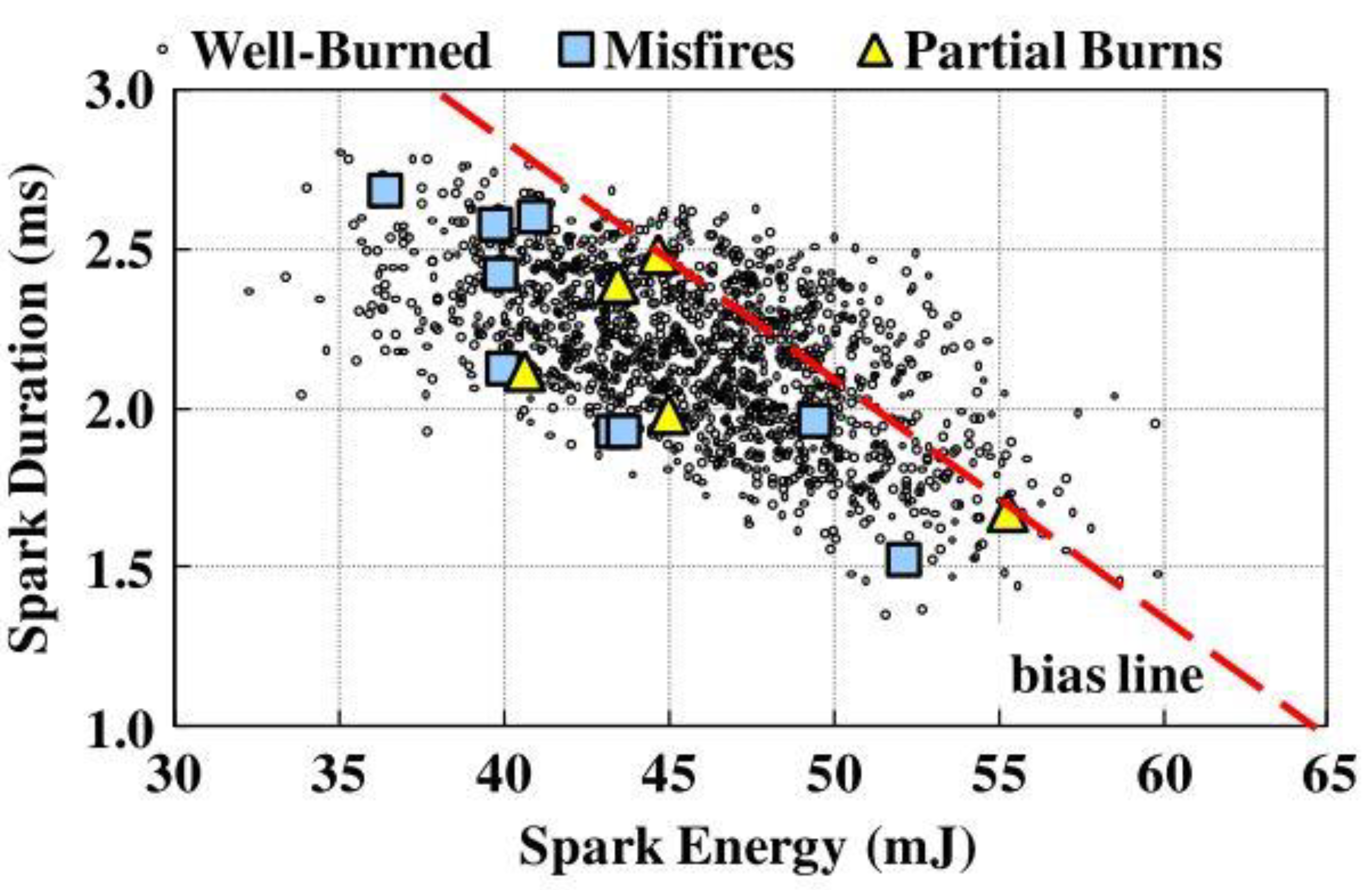
Figure 1. The range of spark duration and spark energy during well-burned, misfire, and partial burn cycles [12].
Energies 16 01604 g001
Figure 2. Classification of thermal and non-thermal plasma according to temperature regimes (figure modified from [15]).
Energies 16 01604 g002
Figure 3. Cross sectional view of plasma jet igniter [16].
Energies 16 01604 g003
Figure 4. Schematic diagram of a (a) railgun and the arc moving process of (b) a rail plug [17].
Energies 16 01604 g004
Figure 5. Schematics of the combustion engines ignited by: (a) a spark plug, (b) a laser, and (c) shows multi-point ignition.
Energies 16 01604 g005
Figure 6. Comparison of the ignition probability of the laser ignition and conventional spark plug [24].
Energies 16 01604 g006
Figure 7. Schematic of a volumetric plasma igniter and ignition characteristics according to the applied voltage and ambient pressure [32].
Energies 16 01604 g007
Figure 8. Images of (a) the corona igniter and (b) the combustion initiation of the conventional spark plug and corona igniter [34].
Energies 16 01604 g008
Figure 9. Flame fronts evolution; λ = 1.6. Images are cropped in correspondence to the optical limit (30 mm radius) [40].
Energies 16 01604 g009
Figure 10. Comparison of PIV images between: (a) without the microwave and (b) with microwave-assisted plasma ignition at ∅:0.78 (CH_4); the OH-number density between: (c) without the microwave and (d) with microwave-assisted plasma ignition at ∅:0.76 (CH_4) [45].
Energies 16 01604 g010
Figure 11. Schematic of the microwave-assisted plasma ignition system.
Energies 16 01604 g011
Figure 12. Schematic of (a) a conventional spark plug, (b) a microwave-assisted plasma ignition (∅:0.75) and (c) a flame kernel size result [47].
Energies 16 01604 g012
Figure 13. Emission spectrum from (a) a conventional spark (TCI), (b) a microwave-assisted plasma ignition system (MAPIS) experiment, and an emission comparison by an experiment and SPARTAN simulation (c) TCI, and (d) MAPIS under a 0.1 MPa and air condition [50].
Energies 16 01604 g013
Figure 14. Research and development on the active and passive pre-chamber configurations (image redrawn from [67].
Energies 16 01604 g014
Table 1. Summary of plasma jet ignition studies.
AuthorAffiliationMain ParameterMain ResultsEnergy Per eventRef.
YoshidaNihon Univ.Orifice area↑
(Chamber exp.)
Peak pressure↑
Combustion duration↓
5.0 J[16]
GaoUniv. Texas at AustinRail plug application
(Engine exp.)
Lean limit↑
Combustion stability↑
[18]
KimMississippi state UnivA/f ratio↑
Ignition energy↑
(Chamber exp.)
Lean limit↑
Flame speed↑
2.03 J[20]
OgawaNihon Univ.Cavity volume↑
(Chamber exp.)
Luminous area ↑
Penetration depth ↑
5.0 J[21]
GaoUniv. Texas at AustinDischarge duration↑
Ignition energy↑
(Engine exp.)
Combustion stability↑
Combustion duration↓
0.3–1.5 J[17]
SasakiNihon Univ.Cavity depth↑
Orifice diameter↑
Ignition energy↑
(Chamber exp.)
Peak pressure↑
Plasma jet velocity↑
2.5–10 J[22]
Table 2. Summary of the effect of laser-induced plasma ignition on combustion.
AuthorAffiliationMain ParameterMain ResultsEnergy Per EventRef.
WeinrotterVienna Univ. Tech.H2 addition
Multi-ignition
(Chamber exp.)
Peak pressure↑
Combustion duration↓
8–24 mJ[23]
GroßKITLaser energy↑
(Engine exp.)
- Homogeneous
Combustion stability↑
Ignition delay↓
- Stratified
Combustion opposite trend
10—50 mJ[24]
GenzaleGeorgia Inst. Tech.Ignition timing
(Chamber exp.)
Optimized ignition timing2–15 mJ[25]
TsunekaneJST# of ignition↑
(Chamber exp.)
Flame area↑
Ignition limit↑
2.7–11.7 mJ[26]
PavelNational Institute for Laser, RomaniaLaser-induced plasma ignitionEngine brake power↑
BSFC↓
4 mJ[27]
KumarUniv. of TokyoPulse width and pulse repetition frequencyIgnition success rate and ignition delay14.3 mJ[28]
PastorCMT, ValenciaIgnition location
(Chamber exp.)
Optimized ignition location800 mJ[29]
PhuodU.S. DOELaser energy↑Ignition limit↑15–200 mJ[30]
WeinrotterVienna Univ. Tech.Laser-induced plasma ignition
(Chamber exp.)
Ignition limit↑
Peak pressure↑
Ignition delay↓
25 mJ[31]
Table 3. Summary of effect of corona ignition on combustion.
AuthorAffiliationMain ParameterMain ResultsEnergy Per EventRef.
ShiraishiNissan MotorStreamer discharge
(Engine exp.)
Peak pressure↑
Ignition delay↓
Flame speed↑
60 mJ[32]
ShiraishiNissan MotorStreamer discharge
(Engine exp.)
Flame area↑
Flame speed↑
O radical↑
60 mJ[33]
HampeMOT GmbHRFSI application
(Engine exp.)
Peak pressure↑
IMEP↑
Fuel consumption↓
CO, HC, and NOx
Combustion duration↓
>55 mJ[34]
MarianiUni. OrléansRFSI application
Equivalence ratio↓
(Engine exp.)
Combustion stability↑
Lean limit↑
Fuel consumption↓
CO and HC↓
NOx
-[36]
PinedaUni. CaliforniaRF corona discharge ignition application
(Engine exp.)
Combustion stability↑
Fuel consumption↓
Knock↓
265–670 mJ[37]
ZembiUniversità degli Studi di PerugiaRF corona discharge ignition application Equivalence ratio
(Engine exp.)
Active radicals↑
Flame speed↑
35–120 mJ[38]
PoggianiUniversità degli Studi di PerugiaA/f ratioFlame speed↑
Lean limit↑
NOx
50 mJ[39]
CruccoliniUniversità degli Studi di PerugiaFuel, A/f ratioFlame speed↑
Lean limit↑
10–20 mJ[40]
SerizawaDaihatsu MotorHF electric field applicationO radical↑
NOx
120 mJ[41]
Table 4. Summary of effect of microwave-assisted plasma ignition on combustion.
AuthorAffiliationMain ParameterMain ResultsEnergy Per EventRef.
GroffGMMicrowave
(Waveguide exp.)
Flame deflection↑
Flame speed↑
250 W (CW)[43]
MaclatchyAcadia Univ.Microwave
(Waveguide exp.)
Flame speed↑
Flame temperature↑
500 W (CW)
Continuous wave
[44]
StockmanUniv. PrincetonA/F ratio↑
(Waveguide exp.)
Flame temperature↑
OH number density↑
Flame speed↑
Lean limit↑
1.3 kW (CW)[45]
WolkUC BerkeleyInitial pressure↑
(Chamber exp.)
Flame speed↓
Flame deflection↓
225 mJ[47]
HwangKAISTMicrowave
(Chamber exp.)
Lean limit↑
Flame speed↑
700 W[48]
HwangKAISTMicrowave
(Chamber, engine exp.)
Combustion pressure↑
Combustion stability↑
Fuel consumption↓
3 kW[49]
HwangKAISTMicrowave
(Chamber, engine exp.)
Electron temperature↑
Flame speed↑
3 kW[50]
ZhangHuazhong Univ.EGR condition
(Chamber exp.)
Lean limit↑150 mJ[51]
WuHuazhong Univ.uw energy↑Coupled energy↑400–1000 W[52]
IkedaImagineeringMicrowave
(Bench exp.)
OH radical↑
Discharge intensity↑
-[53]
IkedaImagineeringA/F ratio↑
(Engine exp.)
Lean limit↑
Combustion stability↑
CO↓ NOx
-[54]
DefilippoUC Berkeleyuw energy↑
(Engine exp.)
Combustion stability↑
Fuel consumption↓
130–1640 mJ[55]
HammackMichigan state Univ.uw energy↑
(Waveguide exp.)
Flame temperature↑
OH number density↑
200–1000 W (CW)[56]
MichaelUniv. Princetonuw energy↑Flame temperature↑
Flame speed↑
Flame luminosity↑
Lean limit↑
25–50 mJ[57]
Disclaimer/Publisher’s Note: The statements, opinions and data contained in all publications are solely those of the individual author(s) and contributor(s) and not of MDPI and/or the editor(s). MDPI and/or the editor(s) disclaim responsibility for any injury to people or property resulting from any ideas, methods, instructions or products referred to in the content.