1. Introduction
Over the past few decades, energy demand has increased exponentially. The increasing population and rising standards of living are its leading causes. Studies show that the world population is growing daily, increasing energy demand [
1]. With each day that passes, fossil fuels are nearer to being drained [
2]. The world is now concerned with finding alternative ways to produce energy. The Intergovernmental Panel on Climate Change (IPCC) has warned the world that if current practices are not taken into custody, the consequences will be too harsh to handle [
3]. Global warming has increased at an unprecedented rate in mankind’s history. Two suggestions that have been made in response to this problem include using renewable resources and using efficient methods to generate energy. These practices can lead us to environmentally friendly and cost-effective ways of producing power [
4,
5].
Global energy generation from fossil fuels leads to extensive CO
2 emissions. Renewables tend to counter this problem. According to the International Energy Agency (IEA), significant carbon dioxide emissions result from burning coal and oil. Other criteria pollutants emitted by fossil fuels, as listed by the Environmental Protection Agency (EPA), USA, include carbon monoxide (CO), oxides of sulfur (SO
x), oxides of nitrogen (NO
x), lead (Pb) and particulate matter (PM). Conventional power plants based on fossil fuel also add to the emission of non-criteria pollutants such as hydrocarbons. A considerable increase in energy demand was experienced from 2011 to 2022, in which energy requirements increased by 100% [
6,
7]. With this rising energy demand, alternative sources must be explored. The studies published in the past two decades show that the world is interested in geothermal sources as a second option for power generation. The demand for energy of the rising population needs to be fulfilled by alternative energy generation methods, among which geothermal resources stand first.
Renewables are a great source for producing energy. By 2035, renewable energy is expected to be the most important source of energy generation, with an annual rise of about 3%. Renewable energy consumption is expected to treble by 2035 [
8]. Considering renewables as a source, multigenerational systems are of great relevance. A multigenerational system (MGS) is a system which produces multiple outputs while having one or multiple primary sources. This system’s main goal is to reduce energy waste and increase performance. These systems are better because they not only produce power but also some by-products, such as hydrogen gas, potable water, space heating, etc., in significant amounts which can be used for different purposes. For instance, take a system which produces power by using a high-temperature source and dumping the waste heat into a low-temperature heat sink.
The product of this system would not be limited to power or energy only if the wasted heat is again utilized for space heating or other purposes, increasing the system’s efficiency. A study by Towhid et al., in which the Kalina cycle generates power, states that the thermal exergetic efficiencies are 62.79% and 33.82%, respectively, for a source temperature of 160.5 °C. Geothermal and LNG cold energy are their primary sources [
9]. Hosein et al. proposed a multigeneration system which also uses Kalina. The main outputs are hydrogen, power and cooling. The system produces 258.6 kW of cooling with a thermal efficiency of 22.28%. The authors stated that if the evaporator’s temperature is increased, no significant effect is observed on power production [
10].
Fatih et al. have proposed a double flash binary power plant multigeneration system (MGS). Their study shows that high-temperature values enhance the system’s performance while a higher flash pressure reduces efficiency, which is an important issue [
11]. A flash binary geothermal system was proposed by Kun Li et al. which, along with producing 782 kW of power, is a cost-effective and efficient system [
12]. The geothermal source used would have a limited efficiency due to the Carnot Factor. Studies show that a typical geothermal source has efficiencies somewhere between 9.5% and 18%, which means that approximately 85% of the energy is wasted. Not only does MGS produce by-products, but it also reduces energy waste, leading to a considerable boost in the system’s efficiency [
5]. Farayi, Shoaib and Rasikh have investigated different configurations of a multigeneration system and found out that the part of the system, the absorber in their case, which accepts heat at first has the highest exergy destruction and that its exergy efficiency is low [
13]. Moreover, Ali et al. stated that deeper wells have a higher tendency to increase system efficiency compared to other wells that are not as deep [
14]. Sameer et al. affirmed in their study that when a geothermal source’s temperature increases, the fresh water production rate decreases, which is an important parameter to be considered [
15].
A study of the combined effect of cooling, heating and power (CCHP) using an air-cooled cascade system conducted by Nattaporn et al. shows that the system has higher efficiency regarding the first law of thermodynamics and a lower efficiency regarding the second law, which indicates the thermodynamic aspects of the system [
16]. Yan et al. developed a system that produced 1.264 GWh of energy with an energy efficiency of 60% and exergetic efficiency of 21%. They found out that when there is an increase in geo-fluid mass flow rate, the power output increases and exergetic efficiency decreases. On the contrary, when there is an increase in
of sea water, the phenomenon is reversed from the previous one as the power output and exergetic efficiencies decrease [
17]. Hojat et al. multi-optimized a multigenerational system to produce energy, water and hydrogen gas using renewables along with liquefied natural gas (LNG) as primary sources along with an evolutionary algorithm. This system’s exergetic efficiency is 52.65% with a cost of USD 4.35/GJ [
18].
The effect of geothermal source temperature has an eminent impact on output values. Power production and efficiency also depend on the cycles used. A study conducted by Murat and Dincer on a geothermal sourced plant with an added option of storage for six outputs stated that if the temperature of reference fluid and geothermal fluid temperature is increased, hydrogen production can be enhanced. Moreover, they noted that the exergetic efficiency increases if fluid mass per unit of time increases [
19]. Shahid et al. studied MGS, having combined primary sources of solar and geothermal energy. He has found that a double organic Rankine cycle (2-ORC) system is far better than a single ORC system. The efficiencies of the system using two ORC are 62% and 54%, while for a single ORC system, these are 51% and 22%, respectively, which clearly shows that the 2-ORC system is superior to the 1-ORC system [
20]. Olusola et al. stated that the Kalina cycle increases the system’s electricity production by 14%. It also increased the system’s efficiency from 68.73% to 70.08% [
21]. Ratlamwala et al. found that three factors are responsible for a change in the system’s outputs. These are ambient temperature, solar irradiance, and temperature gradient [
22]. Different studies conducted by various researchers tell us about other aspects of the system. Mohammad et al. found out that if the turbine’s expansion ratio was high, the exergy efficiency would be higher. Linda et al. found the system’s thermal efficiency to be 37.85%, having sources from Salaban geothermal wells with a temperature range of 170–210 °C. Monu et al. researched a multigeneration system and found that the most considerable exergy destruction was in the boiler and combustion chamber. He found the system’s exergetic efficiency to be equal to 20% while using the organic Rankine cycle [
23,
24,
25].
Bozgeyik et al. did a performance analysis of two systems; one of them was a single-generation system, and the other one was a multigeneration system. The single output generating system had energetic and exergetic efficiencies of 13.7% and 50%, respectively, which were lower than the MGS’s efficiencies of 98.6% and 67.7%. This contrast highlights the significance of MGS [
26]. Fahad et al. analyzed a solar plus geothermal sourced MGS having 54.7% and 76.4% as energy and exergy efficiencies, respectively. The COP of energy and exergy were 0.77 and 0.41, respectively. He further found that source temperature is the most influential element in a system [
27]. Hadi et al. proposed a multigeneration system that produces by-products such as fresh water and electrical power with a thermal efficiency of 94.84% and an exergy efficiency of 47.89%. It was observed that a high evaporation temperature would result in high exergy efficiency [
28]. The source temperature is the most influential entity of the system in its efficiency and performance. The temperature range also affects the exergy efficiency. Ratlamwala et al. predicted the rise in exergetic efficiency from 0.20 to 0.28 with an increase in temperature of 100 K. Montaser et al. conducted a review study of different multigeneration systems for hydrogen production and stated that multigeneration systems have a great potential for sound output as compared to conventional methods. The hydrogen generation varied from 6 to 13,500 [kg/h] depending on the type of system used [
29,
30,
31,
32].
The present study presents a novel multigeneration system which consists of three subsystems: (a) Regenerative Rankine Cycle, which produces power, hydrogen and space heating. The generated electricity can be used for domestic or commercial purposes. Hydrogen can serve as fuel. (b) A double effect vapour absorption cycle, which produces cooling and dry air, which are helpful for domestic purposes. (c) A double flash desalination cycle to distil sea water to fresh potable and hot water, which are very useful for living beings. A comprehensive and novel approach was carried out in this research. This study used an efficient system to conduct a detailed analysis in which mathematical modelling, parametric optimization, and exergy analysis were performed. The working conditions of all the subsystems were considered as well. A mathematical model-solving software, Engineering Equation Solver (EES), was used to carry out thermal and exergetic analysis. Exergy destruction analysis was also carried out.
2. System Description
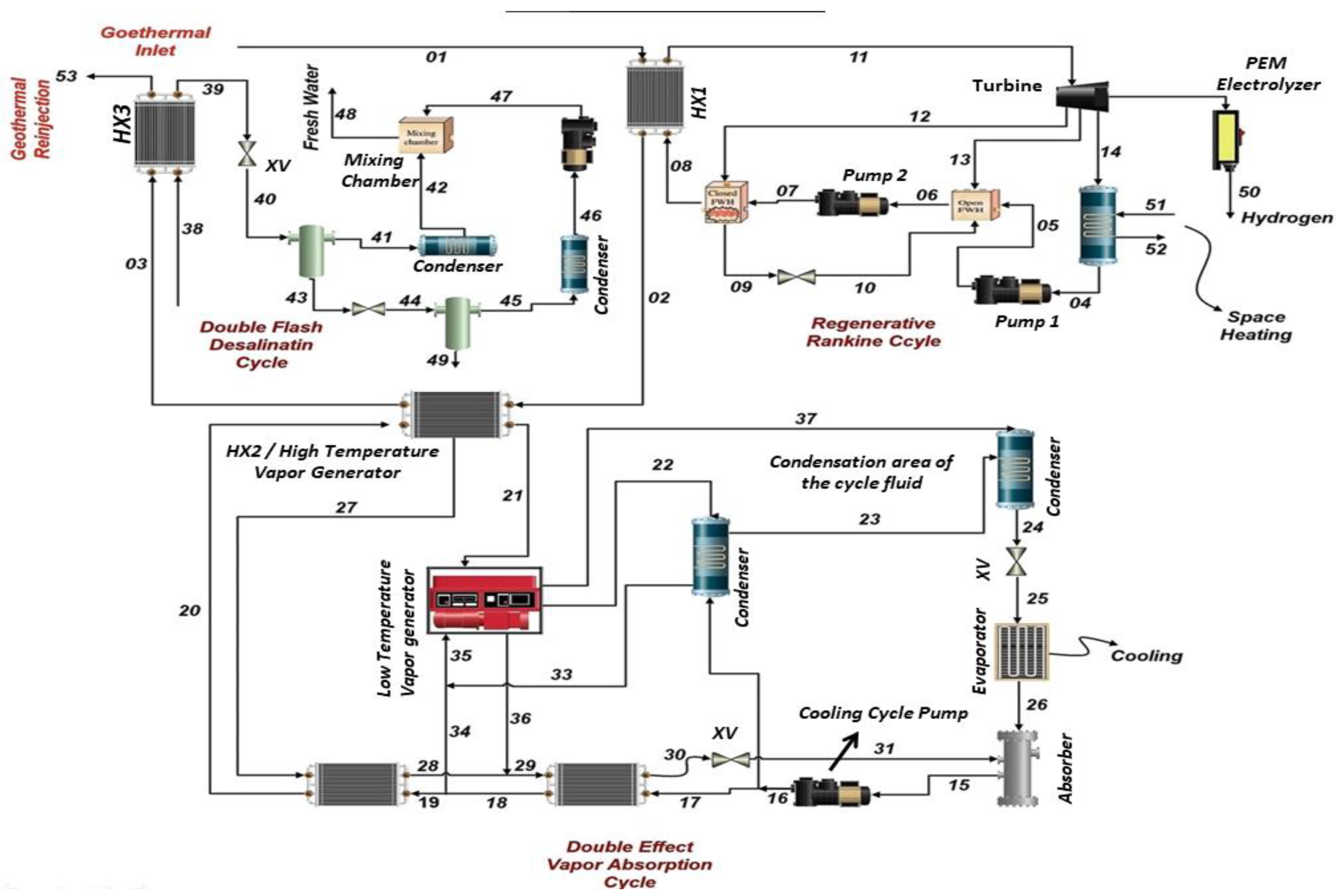
A multigenerational system is a system which produces multiple outputs while having one or two inputs as shown in
Figure 1. The system developed in this study is a multigenerational system which creates electrical power, space heating, cooling, dry air, fresh water, hot water and hydrogen, which may be used for different purposes. The system consists of three subsystems: power cycle, cooling cycle and desalination cycle. The power cycle is the Regenerative Rankine Cycle, the cooling cycle is a double effect vapour absorption cycle and the desalination cycle is a double flash desalination cycle. The source used is dry steam with a temperature of 388 °C (661.15 K) and is located in Cerro Prieto, Mexico [
33].
As the name suggests, the power cycle produces electric power, a fraction of which is further used to generate hydrogen. This cycle consists of a heat exchanger, turbine, condenser, two pumps, an expansion valve, a close-feed water heater and an open-feed water heater. An electrolyzer is also attached to the turbine. The geothermal source, dry steam in this case, is extracted from the well at 388 °C with a flow rate of 300 kg/s and is fed to the heat exchanger at 1, as shown in
Figure 1, which heats the cycle fluid of the power cycle. The locations where geothermal temperature can exceed 250 °C are Yangbajain, China (250–330 °C), Bedugul, Indonesia (280–330 °C) and Larderello, Italy (300–340 °C). The high-temperature geothermal source was selected to increase the efficiency of the system. An appropriate flow rate value was given, as it is a significant factor for power generation. The studies with similar flow rate values are Karapekmez et al. and Rizvi et al. [
33,
34,
35,
36]. The heated cycle fluid enters the turbine at state 11 at a higher temperature, producing electricity. A percentage of the electrical power is used to run an electrolyzer which produces hydrogen. The cycle fluid at state 14 is then sent to the condenser to condense it to the liquid state and lower its temperature. The condensed fluid is then fed into a pump at state 4 and sent to the close-feed water heater. A fraction of the cycle fluid is directly sent to the closed FWH, which is pumped (through pump 2) to increase its pressure. The mixing chamber is attached to pump 2 and the closed FWH, where the fluid gets mixed and fed to the first heat exchanger to repeat the procedure. This cycle is repeated to generate electricity and hydrogen.
Heat exchanger 2 controls the cooling cycle, a double effect vapour absorption cycle. A pump, low-temperature HX, high-temperature HX, high-temperature generator (HTG), low-temperature generator (LTG), condenser, condenser (con), expansion valves, evaporator (eva) and an absorber are all part of the cooling cycle (abs). The pump is where the cycle begins. The absorber’s strong solution is pumped to achieve high pressure. The condenser receives 20% of the solution, while the low-temperature heat exchanger receives the remaining 80%, which exchanges heat with the weak solution from the low-temperature vapour generator. The output of the low-temperature heat exchanger (LTHX) is then sent to the high-temperature heat generator (HTHX), from which a fraction of about 20% is removed and sent to the low-temperature vapour generator. The remaining 80% is sent to the high-temperature heat exchanger, which exchanges heat with the heated weak solution from the high-temperature vapour generator (HTG), before being sent to the high-temperature generator to exchange heat with heat exchangers. This ammonia–water (NH3-H2O) solution is separated into two halves after receiving heat from a geothermal source. The first goes into the low-temperature generator (LTG), while the second goes into the high-temperature heat exchanger. The initial half of the solution is supplied to the condenser, then sent to the condenser again to reject heat to the environment. The weak component of the ammonia–water solution is then passed via a high-temperature heat exchanger before being transferred to a low-temperature heat exchanger. The pressure of the weak solution is dropped by the expansion valve attached to the low-temperature heat exchanger’s output for it to mix with the strong solution from the evaporator. The strong solution sent to the condenser is redirected to a condenser, where it is condensed and transmitted to an expansion valve whose sole function is to expand the solution. This enlarged solution is then put into an evaporator, which absorbs heat from the surroundings before being fed into an absorber. The strong and weak solutions are combined and the cycle begins again. The cooling is produced by the cooling cycle’s evaporator, which has a capacity of 1125 kJ/s.
The double flash desalination cycle consists of a heat exchanger, two separators, two expansion valves, two condensers, a pump, and a mixing chamber. The geothermal source and salt water are fed to the heat exchanger 3. A geothermal source from heat exchanger 2 is used to heat up the saltwater passing through heat exchanger 3. The geothermal source is then re-injected into the ground. After being heated, the saltwater is fed to an expansion valve, which expands and is inserted into the separator where the liquid and vapour are separated. The liquid produced is fresh water. The remaining vapour from separator 1 is then expanded through expansion valve 2, and then the liquid is separated by separator 2, which is condensed through a condenser. The condenser’s output liquid has a comparatively lower pressure than the output liquid of separator 1. So, a pump is used to increase pressure at the outlet of the condenser, which is then sent to the mixing chamber. The outputs of separator 1 and the condenser are mixed in the mixing chamber, and fresh water is produced, which may be used for domestic purposes. The electrolyzer operates by using a fraction of the power produced by the Regenerative Rankine Cycle. This subsystem has 56% efficiency [
37].
4. Results and Discussion
The proposed model produces multiple outputs with a single input, i.e., a geothermal source (dry steam). The outputs include power, heating, cooling, fresh water, hydrogen, dry air and hot water. The main output is power, which can also be used for commercial and domestic purposes. A literature review has been performed to assume input values of temperature and pressure at specific points. The values of mass flow rates were also selected by the method mentioned above. The particular enthalpies and exergies are calculated using enthalpy and exergy functions in Engineering Equation Solver (EES). The multi-level optimization was performed to obtain the most efficient operating conditions. The proposed model is validated by comparing its results to different input conditions used in previous research. The validation of the model confirms its efficacy compared to other systems. This system is designed to use only a geothermal source as its primary and only source, unlike other published studies that use more than one source to produce the same or fewer outputs [
38,
39,
40,
41]. The current study gives us 103 MW of power, 37.6 kg/s of fresh water and 0.122 kg/s of hydrogen, which are better than the mentioned studies [
10,
42,
43,
44].
EES calculates different parameters like temperature, pressure, enthalpy, entropy, exergy, and mass flow rate at other state points of each cycle. These state points are tabulated in the following.
4.1. State Point Values of the Subsystems
The values of different state points of each subsystem are given in this section.
4.1.1. Geothermal Source
Table 1 consists of all three state points, which are 1, 2 and 3. The geothermal source enters at 1 in heat exchanger 1, rejects some heat to the working fluid of the power cycle and exits. It then enters heat exchanger 2 to heat the cooling process working fluid and heat exchanger 3, from which it is re-injected into the ground from which it was taken.
4.1.2. Regenerative Rankine Cycle (Power Cycle)
Table 2 consists of different state point values of the parameters enlisted below. The states included are only for the power production in the power cycle. Hydrogen and space heating are also harnessed through the power cycle but are not included in this table. Mass flow rates of the working fluid of the power cycle at each point are also listed. All the values are obtained from EES.
4.1.3. Double Effect Vapour Absorption Cycle (Cooling Cycle)
Table 3 shows the temperature, pressure, enthalpy, entropy, exergy, and mass flow rate values of each state point in the cooling cycle.
4.1.4. Double Flash Desalination Cycle
Table 4 shows each state point’s temperature, pressure, enthalpy, entropy, exergy, and mass flow rate values in the desalination cycle.
4.1.5. Hydrogen and Space Heating Production
Table 5 shows the state point values of state 50, where hydrogen is produced. State points 51 and 52 are related to heating production, here termed space heating. Different parametric values were calculated using EES and are tabulated here.
4.2. Exergy Destruction and Energy Efficiencies Calculation
4.2.1. Major Exergy Destruction Areas
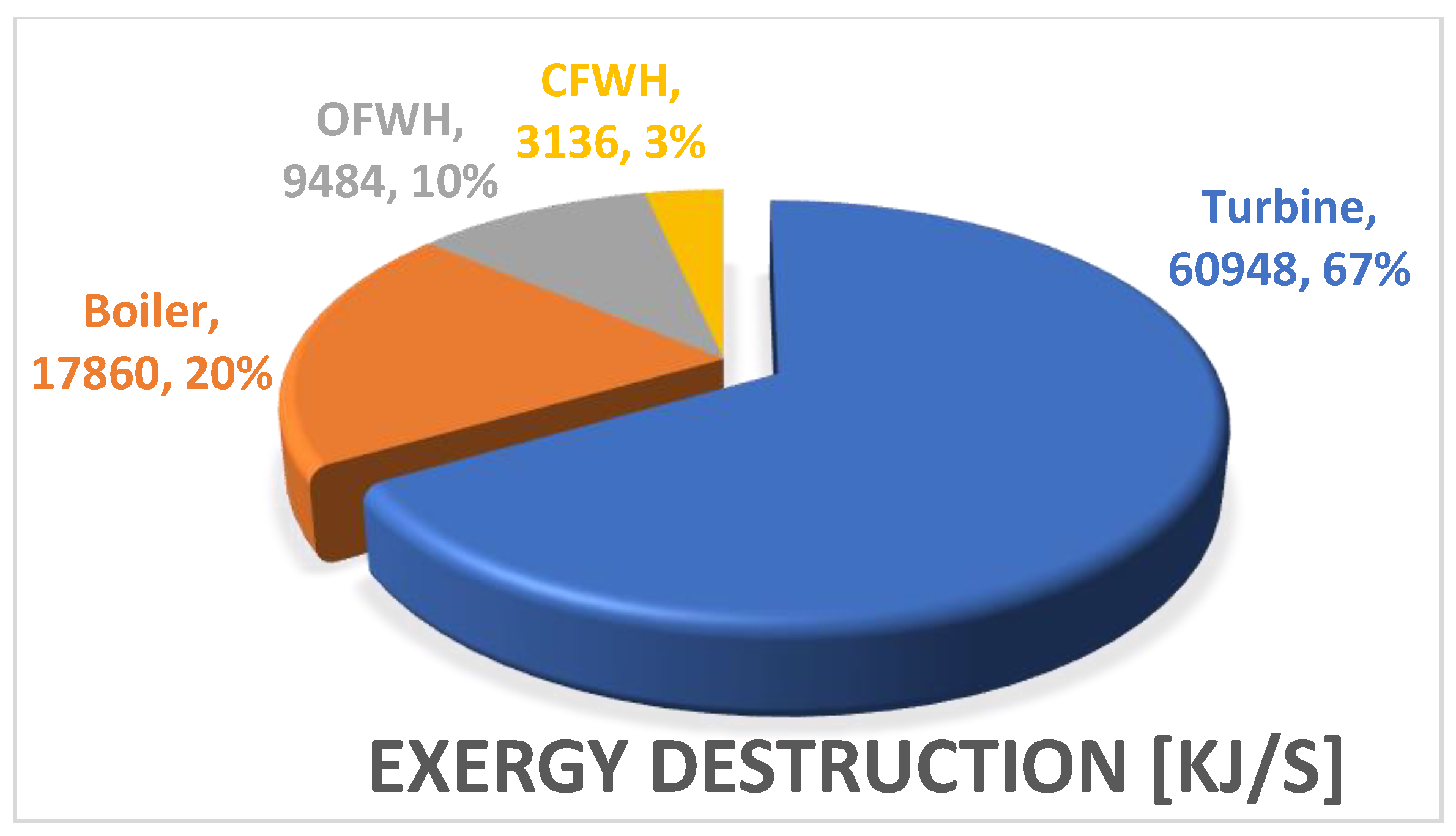
Figure 2 is a pie chart which shows major exergy destruction areas of the multigeneration system. The comparison includes turbine, boiler, OFWH and CFWH, which were chosen based on higher exergy destruction values. The turbine has maximum exergy destruction, which shows high entropy generation. The closed feedwater heater (CFWH) has the lowest among these four components.
4.2.2. Energy Efficiencies at Different Production Loads
Figure 3 shows different energy efficiencies calculated at different production loads of multigeneration system. This comparison is divided into five stages: single generation, meaning only power, double generation, triple generation, quadruple generation and pentuple generation. It can be visualized that the system is more efficient when more outputs are taken from it, which depicts the significance of multigeneration systems. The system is efficient when more products are harnessed because losses are minimized during the single or double generation process. The geothermal source heat is used more effectively, and more energy is harnessed from it, thus making the system more efficient.
4.3. Graphical Representation of Results
The system is optimized to attain the best operating conditions to obtain the maximum possible output. EES is used to perform simulation and plot the graphs to check the effect of geothermal source and ambient temperature on different output values. The following figures show different trends of the impact of source temperature on power output, fresh water and hydrogen production, turbine output, etc. The graph trend for the effect of salinity on fresh water and sea water production has also been plotted.
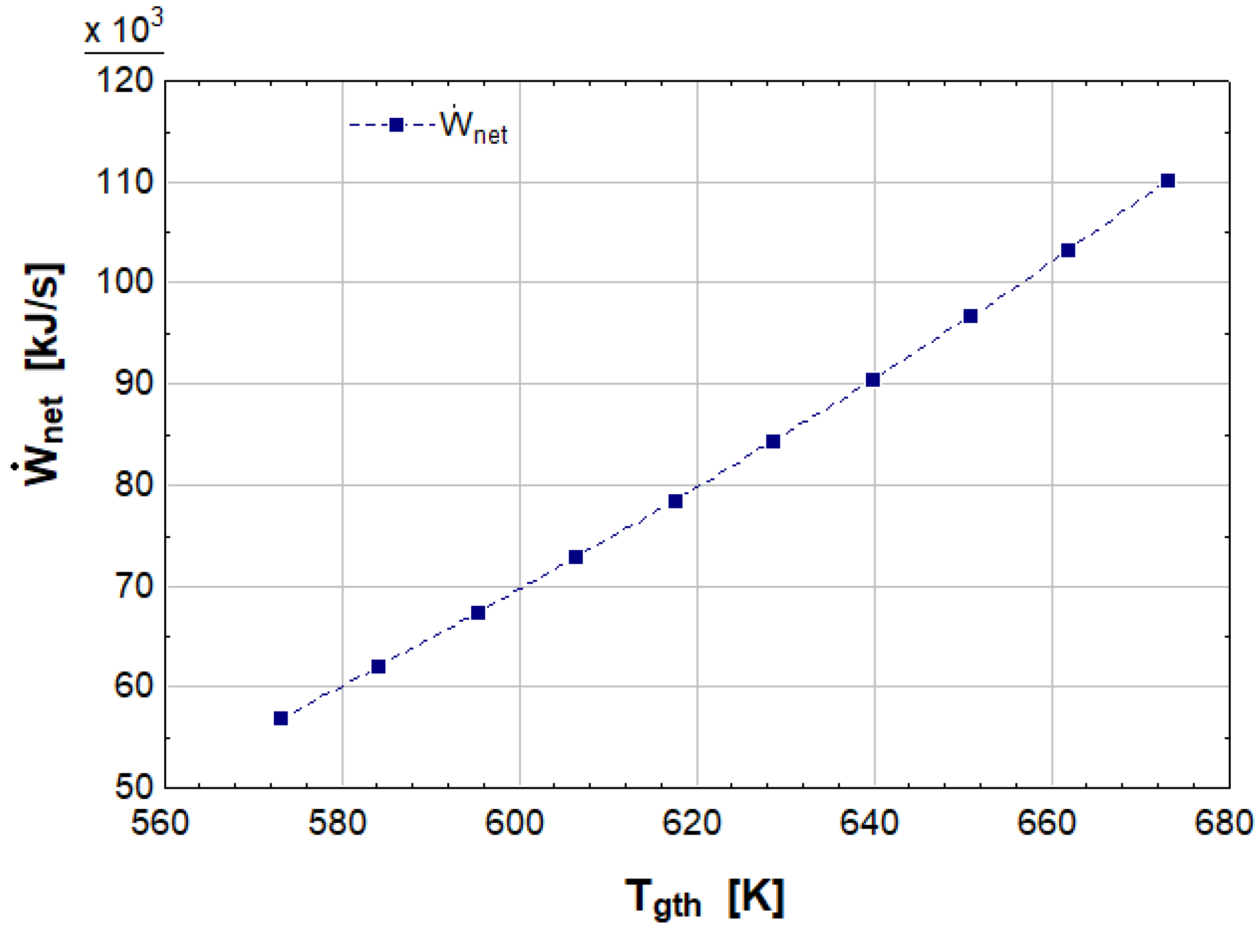
Figure 4 shows the relation of power output with geothermal source temperature. The graph depicts that when the temperature increases, the power output increases as well. There is an exponential increase in the power output when we increase the temperature. For an increase of 100 K from 573 K, the power output increases from 55 MW TO 110 MW, which is a significant increase. The power output is more remarkable because of the higher flow rates through the Regenerative Rankine Cycle. The efficiency of the turbine increases when the source temperature is increased. The reason is the raised area under the curve in the t-s diagram as the fluid gets superheated at higher temperatures.
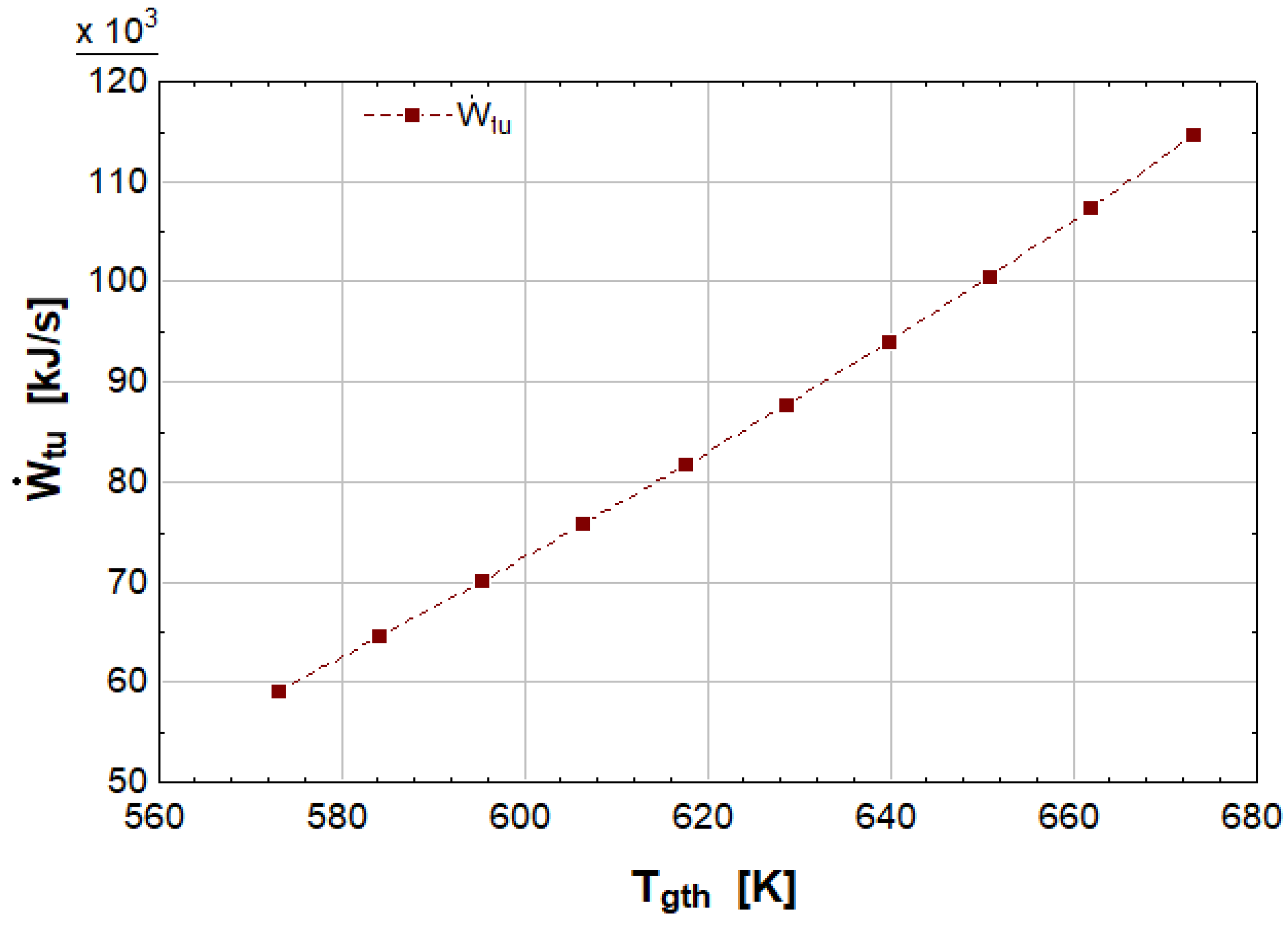
Figure 5 shows the geothermal source temperature’s effect on the turbine’s work output in the Regenerative Rankine Cycle (power cycle). When the source temperature increases, more heat is exchanged in the heat exchanger or superheaters. Thus, the working fluid carries more heat than before, resulting in higher turbine inlet temperature and enthalpy. The higher the enthalpy, the higher the work output from the turbine. This is why the graph shows an increasing trend when the source temperature increases.
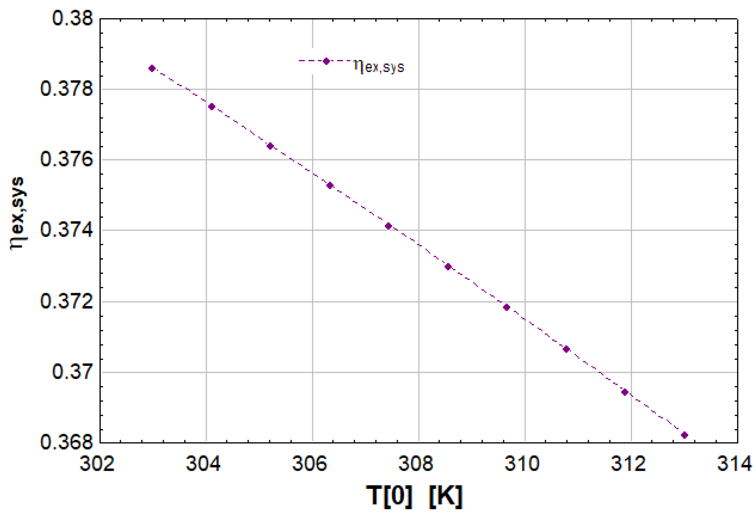
In
Figure 6, the effect of ambient temperature on the exergy efficiency of the system has been analyzed by plotting the graph. The trend goes downwards, showing that exergy efficiency decreases when the atmospheric or ambient temperature rises. If the exergy efficiency is lowered, the system is not sustainable and hence is considered less efficient. If exergy efficiency is greater, the system is more sustainable and efficient. The ambient temperature significantly affects system output as it directly affects the working of turbines. The increased ambient temperature, especially in hot and dry areas, leads to a lower turbine output, resulting in decreased exergy efficiency.
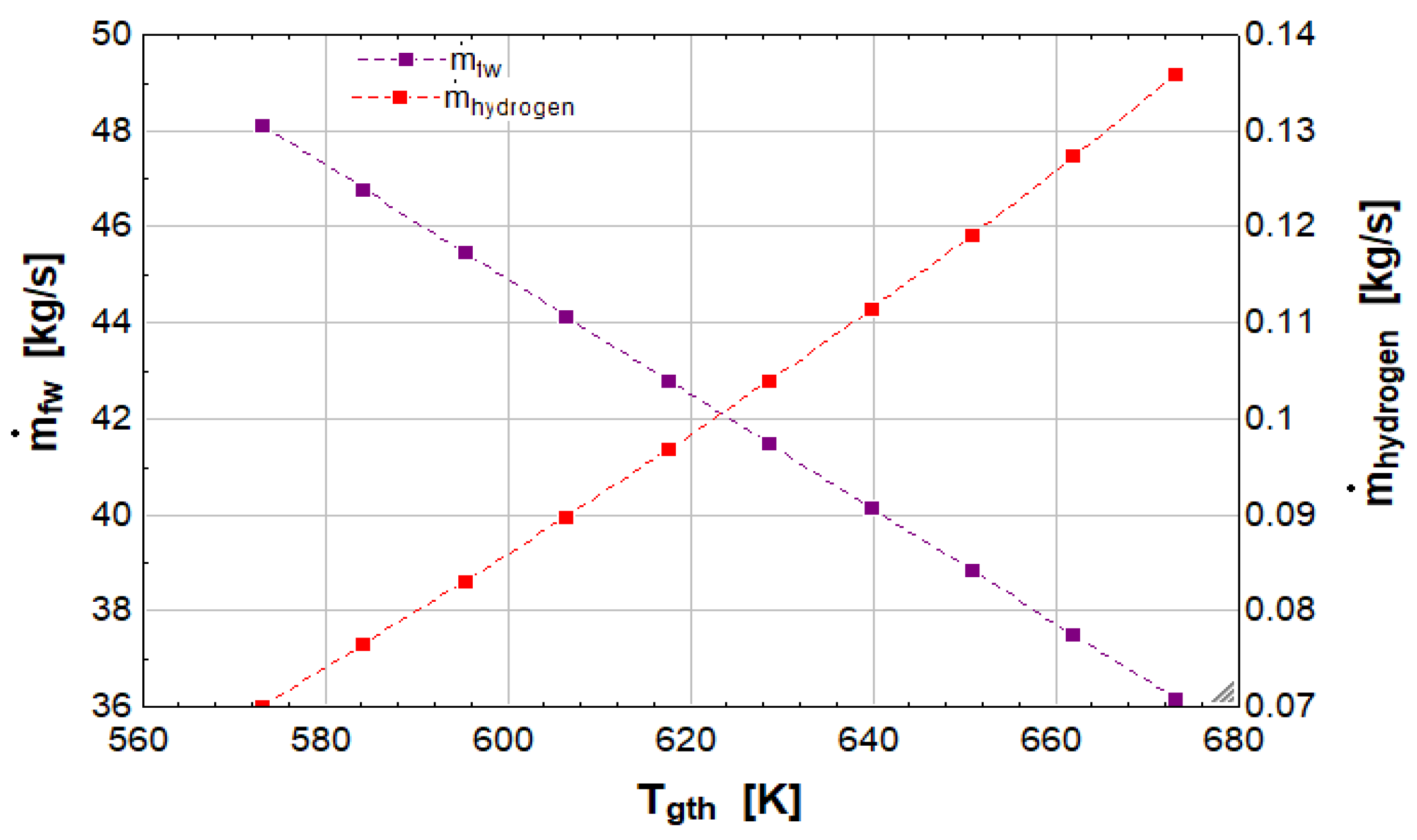
The effect of geothermal source temperature on fresh water and hydrogen production is analyzed by plotting the graph shown in
Figure 7. An increase in source temperature increases power generation, resulting in enhanced hydrogen production as the PEM electrolyzer takes power directly from the turbine. The higher the temperature, the higher would be the power generation and hydrogen production. On the other hand, fresh water generation reduces when the source temperature increases because of the increased evaporation of water due to high temperature.
Figure 8 shows the effect of salinity on the production rate of fresh water and sea water (brine) discharge. Salinity tells us the amount of salt in the water. The trends depict that the higher the salinity, the higher is the fresh water produced. On the other hand, salinity reduces the production or discharge of remaining sea water or brine because most of the injected sea water is used in fresh water production. The salinity value varied from 20 g/kg to 80 g/kg, increasing fresh water production by 4–5 kg/s. The sea water production is reduced by 20 kg/s, which is a significant result.


 ,
, 


