


Minimization of Voltage Harmonic Distortion of Synchronous Generators under Non-Linear Loading via Modulated Field Current

Abstract
:1. Introduction
1.1. Literature Review
1.2. Research Gap
- They are based on time-domain expressions.
- Their implementation requires rotor position and magnetic flux density sensors in addition to the current measurement sensors.
- Due to first and second matters, they have high computational complexity and require extra hardware for their real-time implementation.
1.3. Motivation
1.4. Contributions to the Knowledge
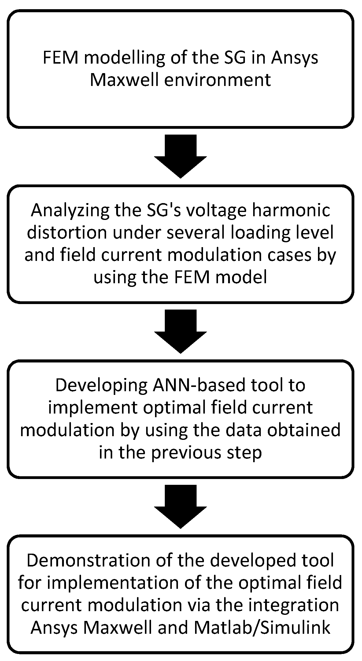
- For the SGs dedicated to supplying non-linear loads, the performance of the field current modulation technique is analyzed for the reduction in the terminal voltage harmonic distortion. To this end, in the ANSYS Maxwell finite element (FE) analysis environment, by superimposing AC current components with various frequencies, magnitudes, and angles on the DC component, numerous field currents are modulated for the excitation of a three-phase salient-pole SG under non-linear loading. In the simulations, several loading levels are also taken into account.
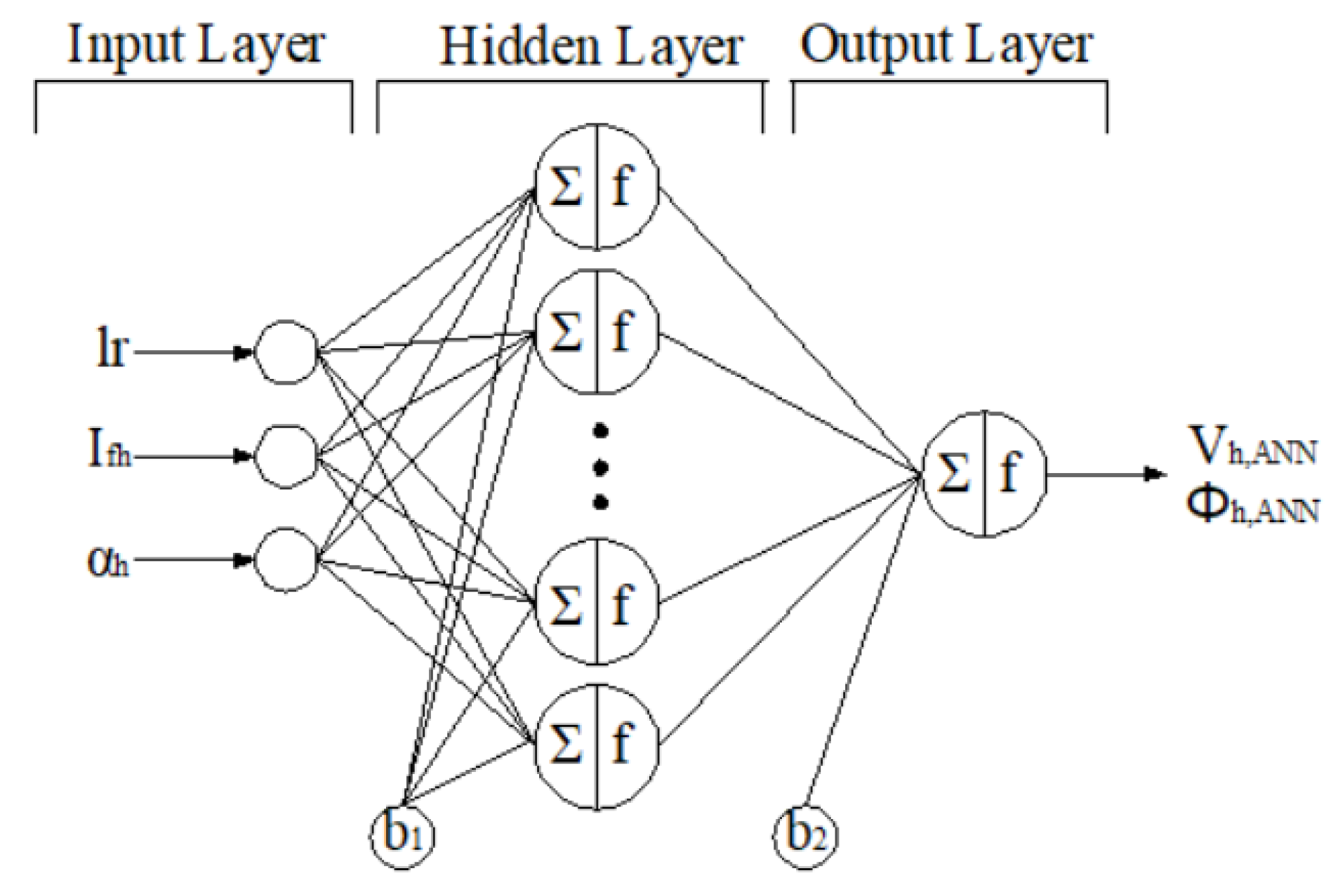
- An ANN model is developed to express terminal voltages’ harmonics in terms of the modulated field current’s harmonic components and the loading level.
- In the ANSYS Maxwell and MATLAB/Simulink environments, the developed model is implemented as a computationally efficient tool to modulate the optimal field current of the SG. In the implementation, the minimization of the terminal voltage harmonic distortion under non-linear loading conditions is considered as an objective.
1.5. Organization
2. Modeling of SG in Ansys Maxwell
3. Harmonic Behavior Analysis of SG under Modulated Field Current Conditions
4. Proposed ANN-Based Model
4.1. Structure
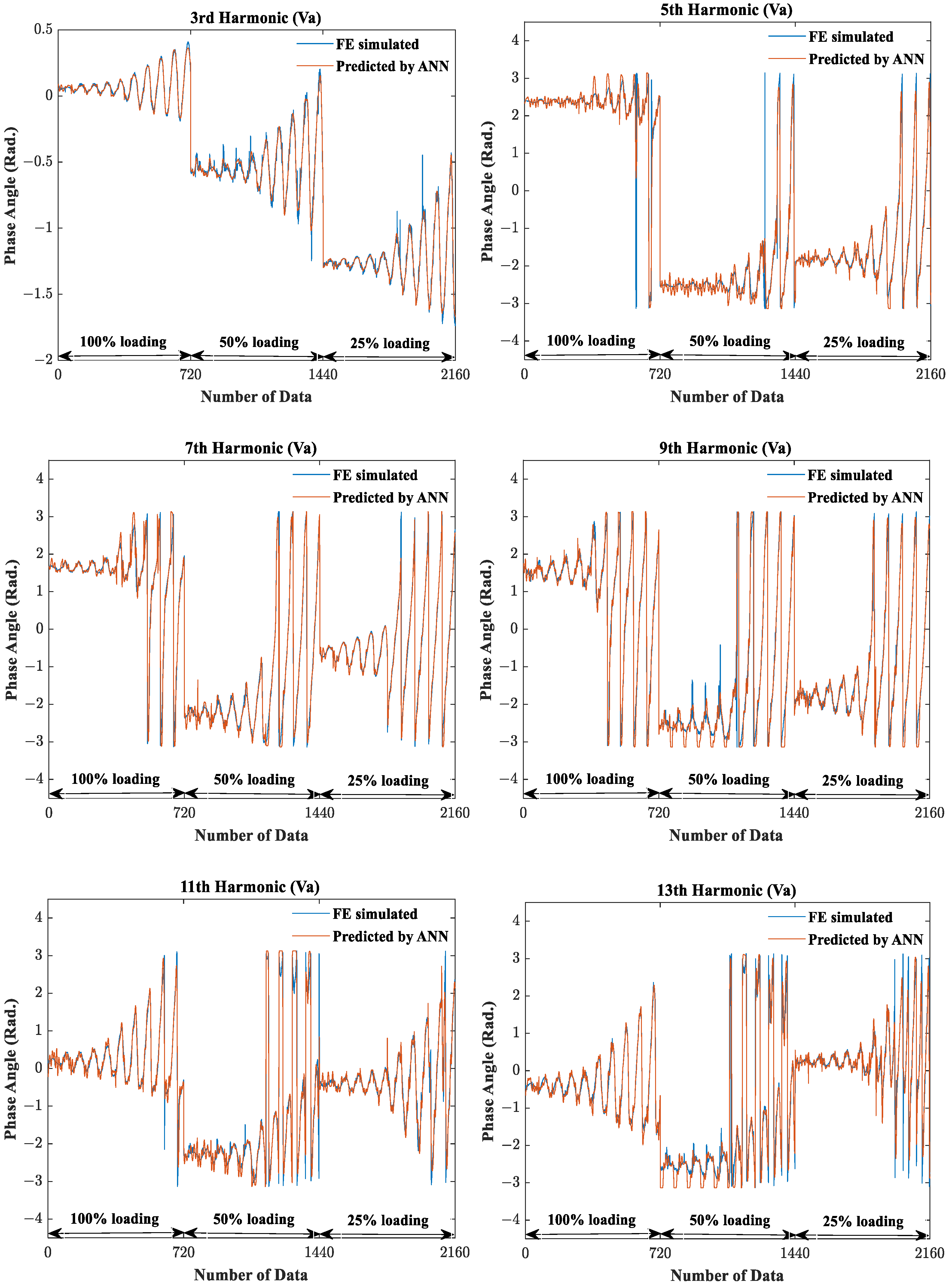
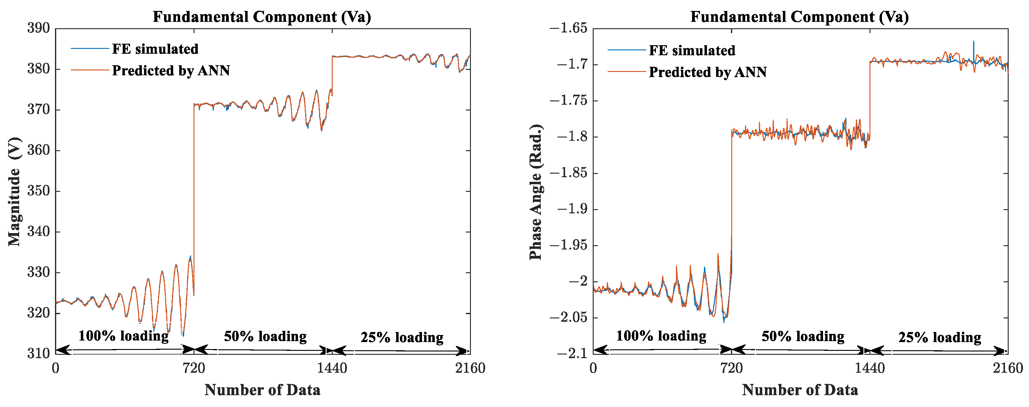
4.2. ANN Results
5. Implementation of the Proposed Model
- In the first part (1), for the loading ratio of the SG, the code embedded in the block searches for the optimal magnitude and phase angle values of the 6th harmonic field current component, which should be superimposed on the DC field current.
- In the second part (2), the s-function block is used for data transition between ANSYS Simplorer and MATLAB/Simulink. It exports the optimal magnitude and phase angle values of the harmonic current component, which is obtained by the first part, to ANSYS Simplorer. It also exports the loading ratio data to ANSYS Simplorer.
6. Conclusions
Author Contributions
Funding
Data Availability Statement
Acknowledgments
Conflicts of Interest
Abbreviations
| ANN | Artificial Neural Network |
| SG | Synchronous Generator |
| FE | Finite Element |
| FRM | Field Current Method |
References
- Michalec, Ł.; Jasiński, M.; Sikorski, T.; Leonowicz, Z.; Jasiński, Ł.; Suresh, V. Impact of Harmonic Currents of Nonlinear Loads on Power Quality of a Low Voltage Network–Review and Case Study. Energies 2021, 14, 3665. [Google Scholar] [CrossRef]
- Buła, D.; Grabowski, D.; Maciążek, M. A review on optimization of active power filter placement and sizing methods. Energies 2022, 15, 1175. [Google Scholar] [CrossRef]
- Wagner, V.E.; Balda, J.C.; Griffith, D.C.; McEachern, A.; Barnes, T.M.; Hartmann, D.P.; Phileggi, D.J.; Emannuel, A.E.; Horton, W.F.; Reid, W.E. Effects of harmonics on equipment. IEEE Trans. Power Deliv. 1993, 8, 672–680. [Google Scholar] [CrossRef]
- Singh, G.K. Power system harmonics research: A survey. Eur. Trans. Electr. Power 2009, 19, 151–172. [Google Scholar] [CrossRef]
- Lumbreras, D.; Gálvez, E.; Collado, A.; Zaragoza, J. Trends in power quality, harmonic mitigation and standards for light and heavy industries: A review. Energies 2020, 13, 5792. [Google Scholar] [CrossRef]
- Balci, M.E. Optimal C-type filter design to maximize transformer’s loading capability under non-sinusoidal conditions. Electr. Power Compon. Syst. 2014, 42, 1565–1575. [Google Scholar] [CrossRef]
- Arslan, E.; Sakar, S.; Balci, M.E. On the No-Load Loss of Power Transformers under Voltages with Sub-Harmonics. In Proceedings of the 2014 IEEE International Energy Conference (ENERGYCON), Cavtat, Croatia, 13–16 May 2014; IEEE: Piscataway, NJ, USA, 2014; pp. 228–233. [Google Scholar]
- Canturk, S.; Balci, M.E.; Hocaoglu, M.H.; Koseoglu, A.K. Investigation of the Effects of DC Bias on Single-Phase Shell Type Transformers Using Frequency-Dependent Reluctance-Based Model. IEEE Trans. Magn. 2021, 57, 1–9. [Google Scholar] [CrossRef]
- Karadeniz, A.; Balci, M.E. Comparative evaluation of common passive filter types regarding maximization of transformer’s loading capability under non-sinusoidal conditions. Electr. Power Syst. Res. 2018, 158, 324–334. [Google Scholar] [CrossRef]
- Ise, T.; Murakami, Y.; Tsuji, K. Charging and discharging characteristics of SMES with active filter in transmission system. IEEE Trans. Magn. 1987, 23, 545–548. [Google Scholar] [CrossRef]
- Hoon, Y.; Mohd Radzi, M.A.; Hassan, M.K.; Mailah, N.F. Control algorithms of shunt active power filter for harmonics mitigation: A review. Energies 2017, 10, 2038. [Google Scholar] [CrossRef]
- Das, J.C. Passive filters-potentialities and limitations. IEEE Trans. Ind. Appl. 2004, 40, 232–241. [Google Scholar] [CrossRef]
- El-Habrouk, M.; Darwish, M.K.; Mehta, P. Active power filters: A review. IEEE Proc.-Electr. Power Appl. 2000, 147, 403–413. [Google Scholar] [CrossRef]
- Abolhassani, M.T.; Toliyat, H.A.; Enjeti, P. An electromechanical active harmonic filter. In Proceedings of the IEMDC 2001, IEEE International Electric Machines and Drives Conference (Cat. No.01EX485), Cambridge, MA, USA, 17–20 June 2001; IEEE: Piscataway, NJ, USA, 2001; pp. 349–355. [Google Scholar]
- Abolhassani, M.T.; Toliyat, H.A.; Enjeti, P. Harmonic compensation using advanced electric machines. In Proceedings of the IECON’01, 27th Annual Conference of the IEEE Industrial Electronics Society (Cat. No.37243), Denver, CO, USA, 29 November–2 December 2001; IEEE: Piscataway, NJ, USA, 2001; pp. 1388–1393. [Google Scholar]
- Karadeniz, A.; Ozturk, O.; Koksoy, A.; Atsever, M.B.; Balci, M.E.; Hocaoglu, M.H. Accuracy assessment of frequency-domain models for harmonic analysis of residential type photovoltaic-distributed generation units. Sol. Energy 2022, 233, 182–195. [Google Scholar] [CrossRef]
- Fan, Z.-N.; Han, L.; Liao, Y.; Xie, L.-D.; Wen, K.; Wang, J.; Dong, X.-C.; Yao, B. Effect of damper winding and stator slot skewing structure on no-load voltage waveform distortion and damper bar heat in large tubular hydro generator. IEEE Access 2018, 6, 22281–22291. [Google Scholar] [CrossRef]
- Fan, Z.-n.; Liao, Y.; Han, L.; Xie, L.-D. No-load voltage waveform optimization and damper bars heat reduction of tubular hydrogenerator by different degree of adjusting damper bar pitch and skewing stator slot. IEEE Trans. Energy Convers. 2013, 28, 461–469. [Google Scholar] [CrossRef]
- Nuzzo, S.; Degano, M.; Galea, M.; Gerada, C.; Gerada, D.; Brown, N. Improved damper cage design for salient-pole synchronous generators. IEEE Trans. Ind. Electron. 2016, 64, 1958–1970. [Google Scholar] [CrossRef]
- Wang, Y.; Nuzzo, S.; Gerada, C.; Zhang, H.; Zhao, W.; Galea, M. Integrated Damper Cage for THD Improvements of Variable Speed Salient-Pole Synchronous Generators for the More Electric Aircraft. IEEE Trans. Transp. Electrif. 2021, 8, 3618–3629. [Google Scholar] [CrossRef]
- Perin, D.; Karaoglan, A.D.; Yilmaz, K. Using grey wolf optimizer to minimize voltage total harmonic distortion of a salient-pole synchronous generator. Sci. Iran. 2021, 1–29. [Google Scholar] [CrossRef]
- Karaoglan, A.D.; Perin, D. Rotor design optimization of a synchronous generator by considering the damper winding effect to minimize THD using grasshopper optimization algorithm. Int. J. Optim. Control Theor. Appl. IJOCTA 2022, 12, 90–98. [Google Scholar] [CrossRef]
- Hyeon Myeong Woo, D.-H.L. Rotor Shape Design of the 10kVA Synchronous Winding Generator Based on Genetic Algorithm for Power THD Reduction. Trans. Korean Inst. Electr. Eng. 2021, 70, 1173–1180. [Google Scholar]
- Gundogdu, T.; Komurgoz, G. Implementation of fractional slot concentrated winding technique to large salient-pole synchronous generators & development with permanent magnets. Electr. Power Syst. Res. 2013, 105, 57–70. [Google Scholar]
- Dajaku, G.; Xie, W.; Gerling, D. Reduction of low space harmonics for the fractional slot concentrated windings using a novel stator design. IEEE Trans. Magn. 2013, 50, 1–12. [Google Scholar] [CrossRef]
- Abdel-Khalik, A.S.; Ahmed, S.; Massoud, A.M. Low space harmonics cancelation in double-layer fractional slot winding using dual multiphase winding. IEEE Trans. Magn. 2014, 51, 1–10. [Google Scholar] [CrossRef]
- Bekka, N.; Zaim, M.E.H.; Bernard, N.; Trichet, D. A novel methodology for optimal design of fractional slot with concentrated windings. IEEE Trans. Energy Convers. 2016, 31, 1153–1160. [Google Scholar] [CrossRef]
- Kimpara, M.L.M.; Pinto, J.O.P.; Fahimi, B.; Ribeiro, P.; Godoy, R.B.; Silva, L.E.B. Field reconstruction method applied for harmonic voltage mitigation in salient pole synchronous generators. In Proceedings of the 2013 Brazilian Power Electronics Conference, Gramado, Brazil, 27–31 October 2013; IEEE: Piscataway, NJ, USA, 2013; pp. 890–895. [Google Scholar]
- Kimpara, M.L.M.; Godoy, R.B.; Ribeiro, P.E.M.; da Silva, L.E.B.; Fahimi, B.; Pinto, J.O.P. A new synchronous machine modeling using the field reconstruction method. J. Control Autom. Electr. Syst. 2014, 25, 481–492. [Google Scholar] [CrossRef]
- Evestedt, F.; Pérez-Loya, J.J.; Abrahamsson, C.J.D.; Lundin, U. Controlling airgap magnetic flux density harmonics in synchronous machines using field current injection. Electr. Eng. 2021, 103, 195–203. [Google Scholar] [CrossRef]
- Lei, G.; Zhu, J.; Guo, Y.; Liu, C.; Ma, B. A review of design optimization methods for electrical machines. Energies 2017, 10, 1962. [Google Scholar] [CrossRef]
- Liu, C.; Chau, K.T.; Lee, C.H.T.; Song, Z. A critical review of advanced electric machines and control strategies for electric vehicles. Proc. IEEE 2020, 109, 1004–1028. [Google Scholar] [CrossRef]
- Nuzzo, S.; Galea, M.; Gerada, C.; Brown, N. A fast method for modeling skew and its effects in salient-pole synchronous generators. IEEE Trans. Ind. Electron. 2017, 64, 7679–7688. [Google Scholar] [CrossRef]
- Zhan, Y.; Kong, K.; Xu, G.; Kang, J.; Zhao, H. Analysis of damper transient currents in salient-pole synchronous generator with skewed armature slots considering interbar currents. IEEE Trans. Ind. Appl. 2018, 55, 336–343. [Google Scholar] [CrossRef]
- Lian, K.L.; Perkins, B.K.; Lehn, P.W. Harmonic analysis of a three-phase diode bridge rectifier based on sampled-data model. IEEE Trans. Power Deliv. 2008, 23, 1088–1096. [Google Scholar] [CrossRef]
- Arvindan, A.N.; Abinaya, B. THD Mitigation in line currents of 6-pulse diode bridge rectifier using the delta-Wye transformer as a triplen harmonic filter. Proc. NPSC 2010, 10, 210–215. [Google Scholar]
- Hadjout, L.; Takorabet, N.; Ibtiouen, R.; Mezani, S. Optimization of instantaneous torque shape of PM motors using artificial neural networks based on FE results. IEEE Trans. Magn. 2006, 42, 1283–1286. [Google Scholar] [CrossRef]
- Wu, H.; Zhang, Y.; Fu, W.; Zhang, C.; Niu, S. A Novel Pre-Processing Method for Neural Network-Based Magnetic Field Approximation. IEEE Trans. Magn. 2021, 57, 1–9. [Google Scholar] [CrossRef]
- Ibrahim, I.; Silva, R.; Mohammadi, M.H.; Ghorbanian, V.; Lowther, D.A. Surrogate-based acoustic noise prediction of electric motors. IEEE Trans. Magn. 2020, 56, 1–4. [Google Scholar] [CrossRef]
- Tahkola, M.; Keränen, J.; Sedov, D.; Far, M.F.; Kortelainen, J. Surrogate modeling of electrical machine torque using artificial neural networks. IEEE Access 2020, 8, 220027–220045. [Google Scholar] [CrossRef]
- Brescia, E.; Costantino, D.; Massenio, P.R.; Monopoli, V.G.; Cupertino, F.; Cascella, G.L. A Design Method for the Cogging Torque Minimization of Permanent Magnet Machines with a Segmented Stator Core Based on ANN Surrogate Models. Energies 2021, 14, 1880. [Google Scholar] [CrossRef]
- da Silva, C.D.L.; Cardoso Junior, G.; Mariotto, L.; Marchesan, G. Phasor estimation in power systems using a neural network with online training for numerical relays purposes. IET Sci. Meas. Technol. 2015, 9, 836–841. [Google Scholar] [CrossRef]
- Beale, M.H.; Hagan, M.T.; Demuth, H.B. Neural network toolbox. User Guide MathWorks 2010, 2, 77–81. [Google Scholar]


| Parameter | Values |
|---|---|
| Rated power | 538 kVA |
| Rated voltage | 400 V |
| Rated frequency | 50 Hz |
| Rotor type | Salient pole |
| Number of poles | 6 |
| Harmonic Order | MSE (Magnitude) | MSE (Phase Angle) |
|---|---|---|
| Fundamental | 4.0361 × 10−³ | 2.0774 × 10−³ |
| 3rd | 9.4757 × 10−³ | 8.6762 × 10−³ |
| 5th | 0.0059 | 0.1683 |
| 7th | 0.0022 | 0.0928 |
| 9th | 0.0096 | 0.1442 |
| 11th | 0.00494 | 0.1467 |
| 13th | 0.0194 | 0.2182 |
Disclaimer/Publisher’s Note: The statements, opinions and data contained in all publications are solely those of the individual author(s) and contributor(s) and not of MDPI and/or the editor(s). MDPI and/or the editor(s) disclaim responsibility for any injury to people or property resulting from any ideas, methods, instructions or products referred to in the content. |
© 2023 by the authors. Licensee MDPI, Basel, Switzerland. This article is an open access article distributed under the terms and conditions of the Creative Commons Attribution (CC BY) license (https://creativecommons.org/licenses/by/4.0/).
Share and Cite
Karakaya, O.; Balci, M.E.; Hocaoglu, M.H. Minimization of Voltage Harmonic Distortion of Synchronous Generators under Non-Linear Loading via Modulated Field Current. Energies 2023, 16, 1789. https://doi.org/10.3390/en16041789
Karakaya O, Balci ME, Hocaoglu MH. Minimization of Voltage Harmonic Distortion of Synchronous Generators under Non-Linear Loading via Modulated Field Current. Energies. 2023; 16(4):1789. https://doi.org/10.3390/en16041789
Chicago/Turabian StyleKarakaya, Oktay, Murat Erhan Balci, and Mehmet Hakan Hocaoglu. 2023. "Minimization of Voltage Harmonic Distortion of Synchronous Generators under Non-Linear Loading via Modulated Field Current" Energies 16, no. 4: 1789. https://doi.org/10.3390/en16041789