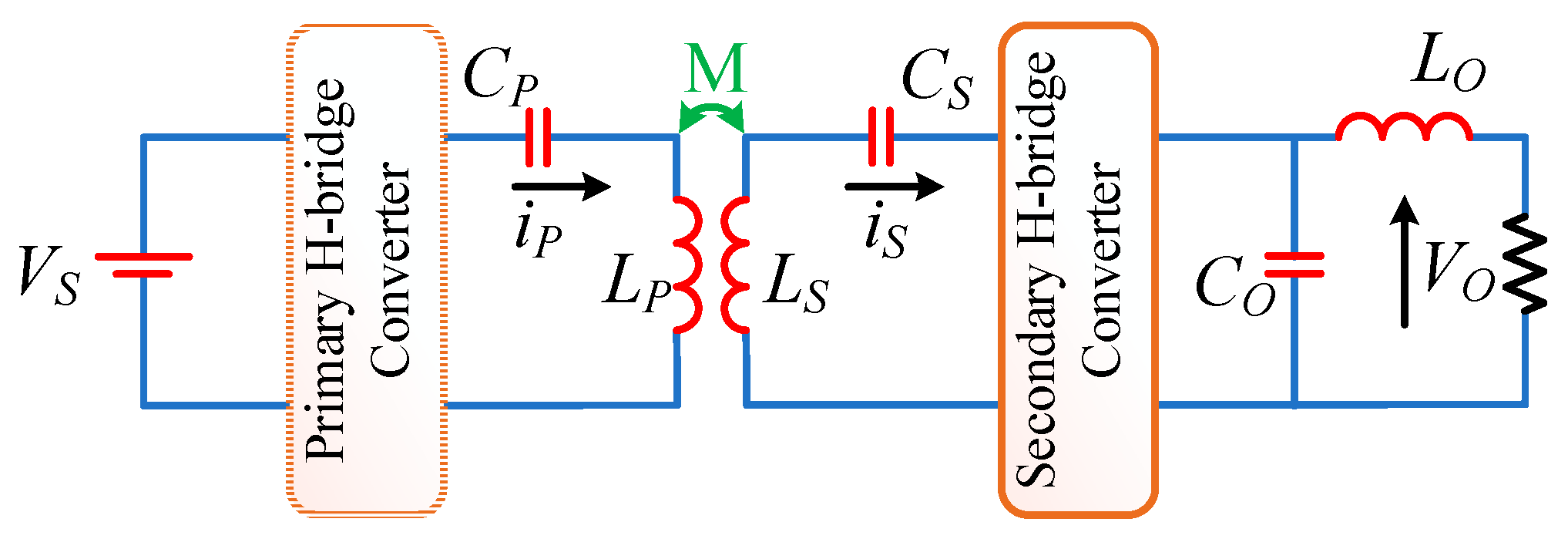
2.1. Circuit Schematic
The schematics of the SAHFWPT and DAHFWPT converters are shown in
Figure 2a,b. The SAHFWPT and DAHFWPT are separated into primary and secondary sections. The primary active H-bridge is designed as the high-frequency primary converter (HFPC), which is powered by the DC source voltages
and
for both the SAHFWPT and the DAHFWPT, respectively. HFPC work as a high-frequency phase shift inverter, generating high-frequency quasi-square wave output voltages
and
. The output current
and
are sinusoidal due to the resonating effect of the coil. Moreover, output voltage waveform level depends on switching control method, as mentioned in
Table 1. The output voltage levels of HFPC by SPS and EPS switching are two and three, whereas in the control operation the HFSC have an output voltage level of two in SAHFWPT and DAHFWPT. Aside from these two switching methods, the DPS and TPS are only useful for DAHFWPT. Since the SAHFWPT secondary is uncontrolled and the resulting voltage is always two levels. The HFPC consists of four MOSFETs (
). Furthermore, if we look at the HFPC schematic in
Figure 2a,b, we can observe the antiparallel body diodes (
) of MOSFETs, that can be operated when the circulating current flow takes place. The coupled coils create the connection between the primary and secondary converter by wireless means. The secondary H-bridges is referred as the high-frequency secondary rectifier (HFSR) or high-frequency secondary converter (HFSC) according to their passive or active operations, respectively. The voltage
and
induced in the secondary coil due to variation in current
and
in the primary coil, according to the Faraday law of induction, secondary voltage serves as the input voltage source of the HFSR and HFSC and the current
and
flow through the secondary coil. The output voltage
and
of the HFSR and HFSC are applied across the equivalent load, which includes the low pass filter
and
equivalent battery resistance, where
can be used to smooth or remove the ripple of voltage
and
, and
can be used to smooth or remove ripple of current
and
. The output voltages
and
, as well as the currents
and
, are kept at the desire levels for charging the battery by the phase-shifted regulation of the HFPC and HFSC. The HFSR and HFSC are fabricated of four high-frequency diodes (
) and MOSFETs (
) with the relevant antiparallel body diodes (
), respectively. The primary side’s input filter is a
filter, which is not seen in
Figure 2a,b.
The switching frequency of the SAHFWPT and DAHFWPT converters are in the range of 79–90 kHz. The operating frequency was fixed at 85 kHz and the resonant circuits are tuned to this frequency as in [
9,
10]. This frequency is selected as per the J2954 standard of the society of automotive engineering (SAE) about charging of electric vehicle through WPT. The design of self-inductor
and capacitors
of the series-series resonating coil are usually at resonating frequency
i.e,
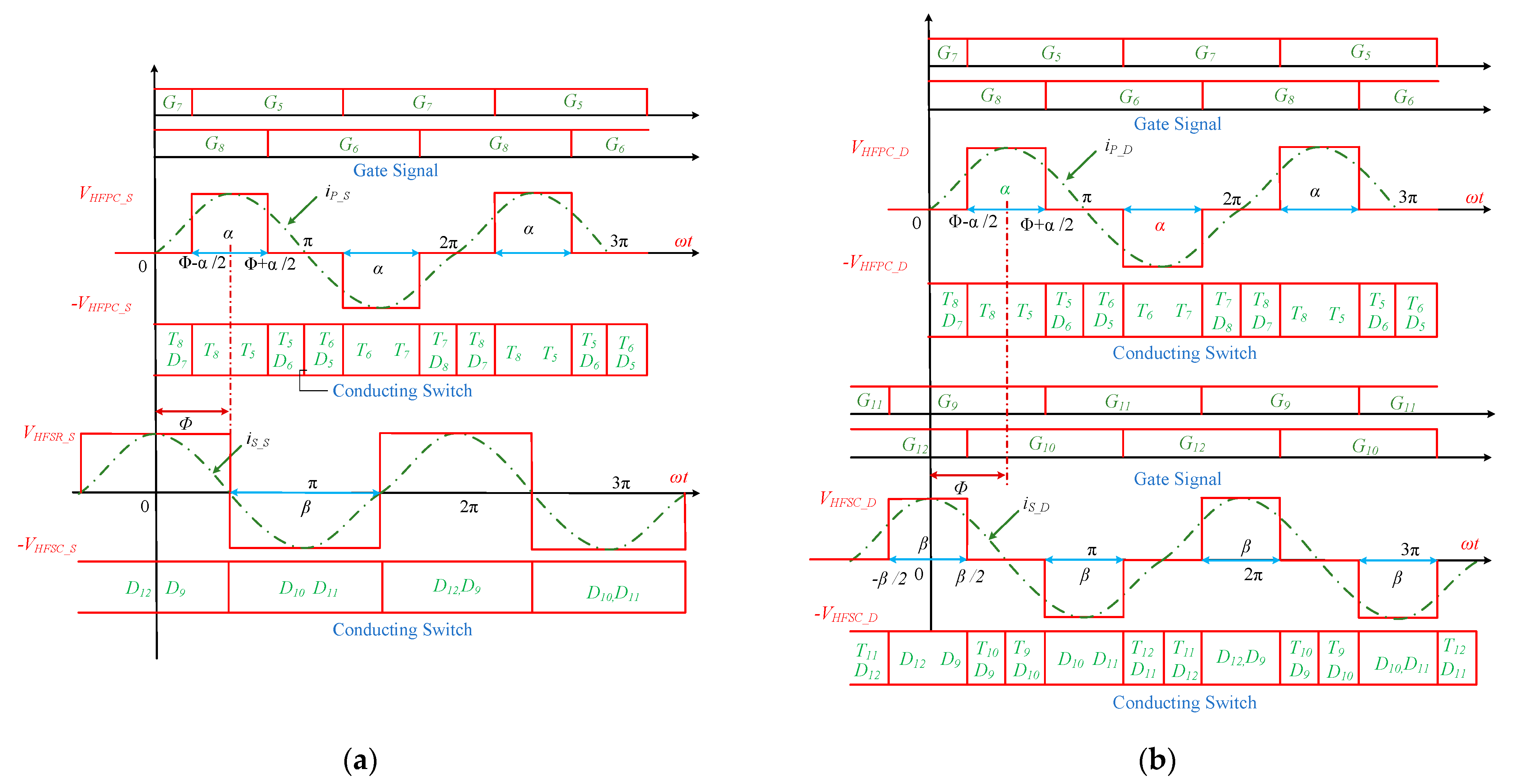
2.2. Operation and Analysis
Figure 3a,b depict the switching operation of the SAHFWPT and DAHFWPT converters at resonance frequency. The EPS and DPS switching mechanisms are used to control the converters of SAHFWPT and DAHFWPT, respectively. The plot is divided in three parts: (1) gate signals of the HFPC on the upper section of the plot, (2) waveforms of current and voltage of HFPC together with the conduction intervals of its switches, (3) and waveforms of current and voltage for HFSR together with the conduction intervals of its switches in the case of SAHFWPT (
Figure 3a) and gate signals. For correlation between both the wave forms, the gate signals in the upper section are assumed same for both SAHFWPT and DAHFWPT, the HFPC switching operation takes place by the internal phase shift angle between its two legs. The middle part of
Figure 3a,b, depicts the direction of current flow through the HFPC’s. During the positive half cycle of the current, three different switching periods can be recognized, namely (1) interval 1: (0 to Φ − α/2), (2) interval 2: (Φ − α/2 to Φ + α/2), and (3) interval 3: (Φ + α/2 to π). While the currents
and
circulate in the MOSFETs and body diode, the circulating current does not flow across the source voltage
and
, respectively. Indeed, the output voltage of HFPC is zero, i.e.,
=
, in the intervals 1 and 3. Switches (T8, D7), and (T5, D6) are in conduction state, as the energy stored in the reactive element such as
and
forces the current to circulate in intervals 1 and 3. Aside from that, the amplitudes of
and
in interval 2 are identical to
and
. The wave forms clearly show that the output voltages
and
square, as well as the currents current
and
sinosuidal, are in the same phase and have half-wave symmetry, due to the resonating behavior of the coil. As per the Faraday law induction, EMF is induced in the secondary coil due to flux linkage between the primary and secondary. The average power
flow from primary to secondary due to induced voltage in the secondary, which can serve as voltage source for the SAHFWPT and DAHFWPT secondary.
HFSR and HFSC converters are passive and active in behavior, respectively. As shown in the lower part of the waveform in
Figure 3a, HFSR conducts for a full cycle, i.e., (
) conducts during the positive half cycle and (
) conducts during the negative half cycle. As a matter of fact, the HFSR input voltage
and current
are square and sin wave, respectively, thanks to the resonating behavior of the coil. On the contrary, the active rectifier HFSC operation during the positive half cycle is divided into three intervals: (1) interval 1: −π/2 to −β/2; (2) interval 2: −β/2 to β/2; and (3) interval 3: β/2 to π/2). In the intervals 1 and 3, the output voltage of HFSC is zero, i.e.,
= 0, while the current
flows in the MOSFETs and body diodes of HFSC and do not reach the load. The switches
and
are in conduction state during the intervals 1 and 3 respectively. The circulation of current occurs due to the energy stored in the reactive elements such as
and
. Apart from this, the amplitudes of
and
are equal to
and
in the interval 2. From the shape of the wave form, it was easy to see that the output voltages
and
square and the currents
and
sinusoidal have the same phase and are half-wave symmetric, due to the resonating behavior of the coil.
The output voltages , and currents , of the HFSR, and HFSC are almost constant due to filtering effect of and . The external phase shift angle for primary and secondary converter is fixed at Φ in the case of SAHFWPT and DAHFWPT.
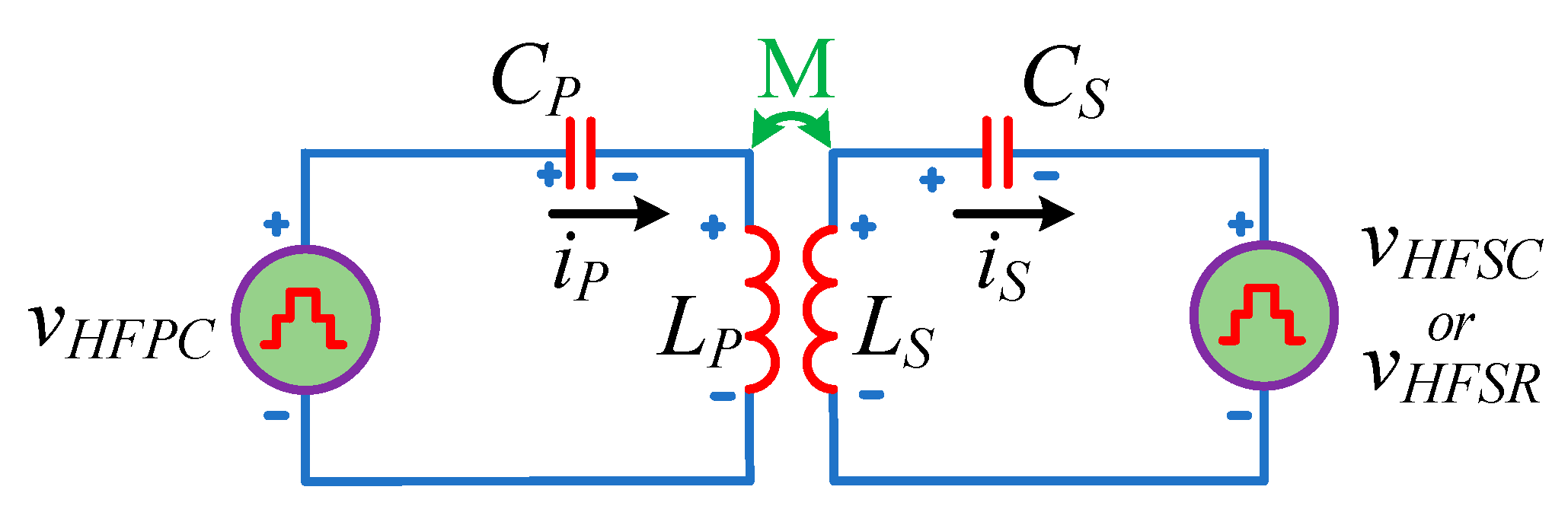
The equivalent circuit of SAHFWPT and DAHFWPT with S-S coupling is shown in
Figure 4. As per
Figure 3 the operation begins at time t = 0, and the internal phase shift angles of HFPC and HFSC are α and β, respectively (whereas in the case of SAHFWPT, β = π is fixed). The external phase shift angle Φ varying in the range [0 2π] during the operation of DAHFWPT (whereas Φ = 3π/2 is fixed in the case of SAHFWPT). The voltages
and
are expressed as a Fourier series as follows:
The maximum values of amplitudes for the first harmonic components of the voltages of the HFPC and HFSC of DAHFWPT are represented by and , respectively. Take into consideration that the external phase shift angle Φ ranges in the interval [0, 2π] for the Bi-directional operation DAHFWPT, whilst for the uni-directional operation, such as power flow exclusively from primary to secondary, the external phase shift angle Φ spans the interval [π, 2π]. However, for maximum power transfer it is Φ = 3π/2. Apart from Φ = 3π/2 value, the power transfer is not maximal due to the reactive current being not in the phase with the HFPC output and HFSC input voltage. This leads the circulating current flowing through the converter and coil.
Since the HFSR is a passive converter, the following conditions hold β = π and Φ = 3π/2, and from (3) the input voltage for the HFSR is expressed as:
The harmonic and maximum harmonic input voltage of HFSR of SAHFWPT are represented by
and
. From Equation (2) it is clear that primary voltage
relation is same for SAHFWPT and DAHFWPT. So from
Figure 3 and
Figure 4 . Indeed the secondary voltage relation is not same, from the
Figure 3 and
Figure 4,
and
, respectively.
Applying Kirchhoff’s voltage law in
Figure 4, we obtain
where
and
internal resistance,
and
self-impedance of coil,
and
voltage drop across capacitor,
and
current flow from the S-S coil,
= M
and
= −M
are the induced voltage of primary and secondary S-S coils, respectively, M is the mutual inductance.
At the resonance frequency, the instantaneous power absorbed by the inductor
,
is equal to the instantaneous power delivered by the capacitor
,
. The net power delivered and absorbed by the capacitor and inductor is zero in the primary and secondary S-S coils, respectively. The impedance of the S-S coils is minimum at the resonating condition. Indeed, primary and secondary coil impedances are minimum; therefore, they represent the internal resistance of the S-S coil, i.e.,
. Therefore, Equations (5) and (6) are re-arranged at resonating frequency as
The voltage and current relationship at fundamental resonance frequency are represented in (8) to (11) for the DAHFWPT, similarly it is represented in (12) to (15) for SAHFWPT, by using approximation
and
for high Q-factor coil [
6]. The expressions DAHFWPT and SAHFWPT are represented at fundamental harmonic approximation of the sinusoidal component in
Table 2 and
Table 3 [
20,
22], respectively.
, and , are the fundamental maximum amplitude and fundamental voltage of HFPC and HFSC, respectively. The secondary fundamental currents , represented in Equations (11) and (15) for DAHFWPT and SAHFWPT, are the same as they only depend on . Moreover, the primary fundamental current of DAHFWPT depends on , while the primary fundamental current of SAHFWPT is constant, as is fixed at π.
The uni-directional power flow was considered only in the case of battery charging, and the rated source voltages
=
= 386 V are constant for SAHFWPT and DAHFWPT; as mentioned in
Table 4 the battery voltage is also same, i.e.,
=
= 120 V. The secondary absolute lossless power for SAHFWPT and DAHFWPT can be express in (16) and (17) by using the (9), (11), (13), and (15)
where
and
are the maximum voltage at the primary and secondary coil. From the Equations (16) and (17), the secondary power can be regulated using the internal phase shift angles α = β ∈ [0, 2π], and external phase shift angle Φ ∈ [π, 2π], while in Equation (16) β = π and Φ = 3π/2. the secondary power of SAHFWPT and DAHFWPT can be related by Equation (18):
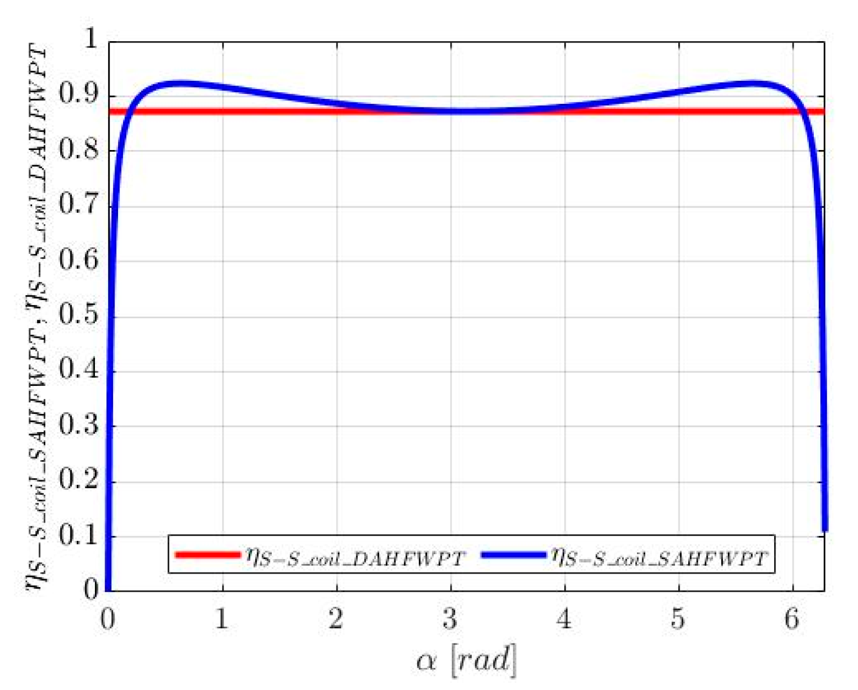
Figure 5 shows the comparison of power curve between DAHFWPT and SAHFWPT of secondary power, w.r.t α, where α is in radian. The power
plotted with the red line, and
plotted with the blue line are directly related with sin(α/2) as mentioned in (18), when we fixed Φ = 3π/2 for maximum power transfer condition. From the power curve, it can be proven that the power of DAHFWPT and SAHFWPT are same at α = 3.14, i.e., π. Apart from that, DAHFWPT power sinusoidal decreases and it is always less than the SAHFWPT power that decreases almost linearly. It is observed in
Figure 5 that SAHFWPT and DAHFWPT have similar instantaneous power, the internal phase shift angle of secondary power of DAHFWPT is always bigger than secondary power of SAHFWPT.


