Article

Novel Passive Radiation Cooling Materials with High Emissivity Discovered by FDTD Method

School of Energy and Power Engineering, Lanzhou University of Technology, Lanzhou 730050, China
*
Author to whom correspondence should be addressed.
Energies 2023, 16(4), 1832; https://doi.org/10.3390/en16041832
Submission received: 12 January 2023 / Revised: 4 February 2023 / Accepted: 9 February 2023 / Published: 12 February 2023

Abstract

:
The cooling with the traditional condensation method leads to huge energy consumption, while increasing attention has been paid to radiant cooling because of its characteristics of no additional energy consumption and no pollution. In order to obtain materials with higher infrared emissivity and better performance for daytime passive radiation cooling materials, the infrared emissivity of different materials was studied based on the finite-difference time-domain method. A new composite material with high emissivity has been found. The results show that the highest emissivity can reach 99.1% by adding Si3N4, Al2O3 and Fe2O3 particles with volume fractions of 6% and diameters of 50 nm into polydimethylsiloxane. This is the most excellent emissivity ever found. By combining the emitting layer made of polydimethylsiloxane mixed with nanoparticles with the reflecting layer made of Ag foil, the new film material can reach a solar transmissivity of 96.4% and a “sky window” mean emissivity of 94.2%. A new composite material with high emissivity and high reflectivity has been realized. The new composite material can be used as a radiation cooling material with good performance and help to solve the cooling problem caused by energy consumption.

1. Introduction

The global average surface temperature increased by about 0.3 °C again in the last decade [1]. The problem of global temperature warming due to human activities has become increasingly serious [2]. In the face of rising temperatures, the need for cooling will increase in the coming decades [3]. However, obtaining cold energy through traditional methods will lead to greater energy consumption, which will lead to more serious environmental problems [4,5]. At present, some novel cooling methods are realized through the passive cooling of phase change materials (PCM) [6,7,8] and passive daytime radiation cooling (PDRC) [9,10]. However, the special feature of PDRC is that the material itself can radiate heat in the form of an electromagnetic wave in the low temperature space (3K) through the atmospheric window (8–13 μm), so as to achieve effective cooling [11,12,13]. Therefore, zero energy consumption and environment-friendly cooling can be realized by PDRC. At present, PDRC is a promising technology in many fields such as building facades (window, roof and wall), solar cell cooling, electricity generation and clothing [14,15,16,17]. Therefore, PDRC technology, as a renewable energy technique with no pollution and zero energy consumption, is of great significance for the field that needs to use fossil fuels for cooling.
In addition to atmospheric radiation, heat conduction and convection between materials and the environment, there are two main factors for improving the PDRC efficiency. The first is to reduce the amount of radiation absorbed by the sun during the day, which radiates between 0.3–2.5 μm at the surface [18]. The high reflectivity of solar radiation in this band is the first characteristic of good radiative cooling materials. In this regard, Zhong et al. obtained a composite with a high reflectance of 98% by adding an Ag deposit layer and expanded polytetrafluoroethylene (PTFE) to a glass substrate, which has a temperature drop of 2.7 °C in cloudy humid areas [19]. Dong et al. used the spectral band complementarity method to find a new PDRC coating. The coating, which contains BaSO4, CaCO3 and SiO2 particles, has a reflectivity of up to 97.6%. At the same time, the coating can reduce the temperature of the covering by 8.3 [20]. In addition, the reflectivity of pure metal materials is found to be more than 96% only for metallic Ag. Although there are other metals with high reflectivity (e.g., Al), they are much less reflective than Ag. Thus, Ag foil is often used in the study of materials with high reflectivity. Some studies have found that the reflectivity of Ag combined with polyester material will produce unexpected effects [21]. For the study on adding Ag to the reflector layer, Yang et al. studied a composite film composed of PTFE and Ag. The thickness of the composite film is 0.24–1 mm, and it can have extremely high reflectance in the band 0.28–4 μm; the reflectance can reach 0.99, which means it is the material with the highest reflectance reported at present [22]. These are some of the ways to reduce the amount of radiation absorbed by the sun during the day. Secondly, if the radiation cooling has a high cooling ability during the day, the emissivity of the material at the atmospheric window (8–13 μm) should be improved [23,24]. Currently, the materials with high emissivity mainly include aerogel, nanoparticle, nanofiber and polymer. Li et al. developed a silica-alumina nanofiber aerogel. Based on the scattered reflection and selective emission of the optical fiber network in the aerogel, the emissivity of the material can reach 93%. The aerogel also has a high reflectivity, of up to 95% [25]. Chae et al. took sapphire as the substrate and attached Al2O3 and Si3N4 thin films on it; they found that the reflectivity of the composed material could reach 96%, the emissivity could reach more than 90% and a temperature drop of 10 °C was observed in the experiment [26]. Zhou et al. studied a thin film thermal emitter combined with polydimethylsiloxane (PDMS) and metal. The thickness of the thin film was more than 100 μm, and the emissivity reached 94.6% in the experiment. It was also measured that after the directionality of the thermal emitter was enhanced, the emitter could reach a temperature drop of 11 °C and a cooling power of up to 120 W/m2 in the open air. Since PDMS materials are cheap, the project can be used on a large scale [27]. Although there are many directions in the research on materials with high emissivity, the research on synthetic materials of polymers and nanoparticles is also increasingly favored by many researchers.
However, in the current research on nanoparticle materials, researchers prepare composite materials by testing the optical characterization of ordinary materials and then by verifying complementary or mutually reinforcing properties. Therefore, many mixtures of materials involving particles need to be simulated in advance using the corresponding software to predict whether the model will work. Li modeled and simulated the radiant cooling film with the finite-difference time-domain (FDTD) method. The final simulation results show that when the volume fraction of SiO2 and SiC is 8% and 1%, respectively, and the thickness of the radiant cooling film is between 60 and 90 μm, the emissivity of the radiant cooling film is more than 90%. Then, experiments were carried out on the basis of the simulation, and the experimental values were basically consistent with the simulated values [28]. Wang prepared a composite material with high emissivity and reflectivity by taking Al as the reflection substrate and PDMS film containing Si3N4 as the emission layer. The emissivity simulated by FDTD is basically consistent with the experimental values. Moreover, it is found that the temperature of the material decreases by 10 °C at most when it is outdoors [29].
In this paper, we design a new composite material. The emission layer of the material is prepared in the form of a mixture of nanoparticles and polymers. Ag foil with high reflectivity, which is easy to obtain and process, is selected as the reflective layer. The new material has the excellent characteristics of high emissivity and high reflectivity. The emission layer materials are selected and combined by Al2O3, Si3N4, SiC, SiO2, Fe2O3 and PDMS with high emissivity in the atmospheric window band (8–13 μm). The emissivity of the composite was simulated by adding different particle diameters, volume fractions and mixtures of different particles into the transparent PDMS film. Three kinds of particles, Si3N4, Al2O3 and Fe2O3, are obtained by simulation and have a good complementary effect on the low emissivity band of PDMS materials. The results show that the highest emissivity can reach 99.1% by adding Si3N4, Al2O3 and Fe2O3 particles with a volume fraction of 6% and a diameter of 50 nm into PDMS. This is the most excellent emissivity ever found. By combining the emitting layer made of PDMS mixed with nanoparticles with the reflecting layer made of Ag foil, the new film material can reach a solar transmissivity of 96.4% and a “sky window” mean emissivity of 94.2%. A new composite material with high emissivity and high reflectivity has been realized. The completion of this research can provide some help to the energy consumption problem of traditional cooling and refrigeration.

2. Accuracy Verification of FDTD Simulation

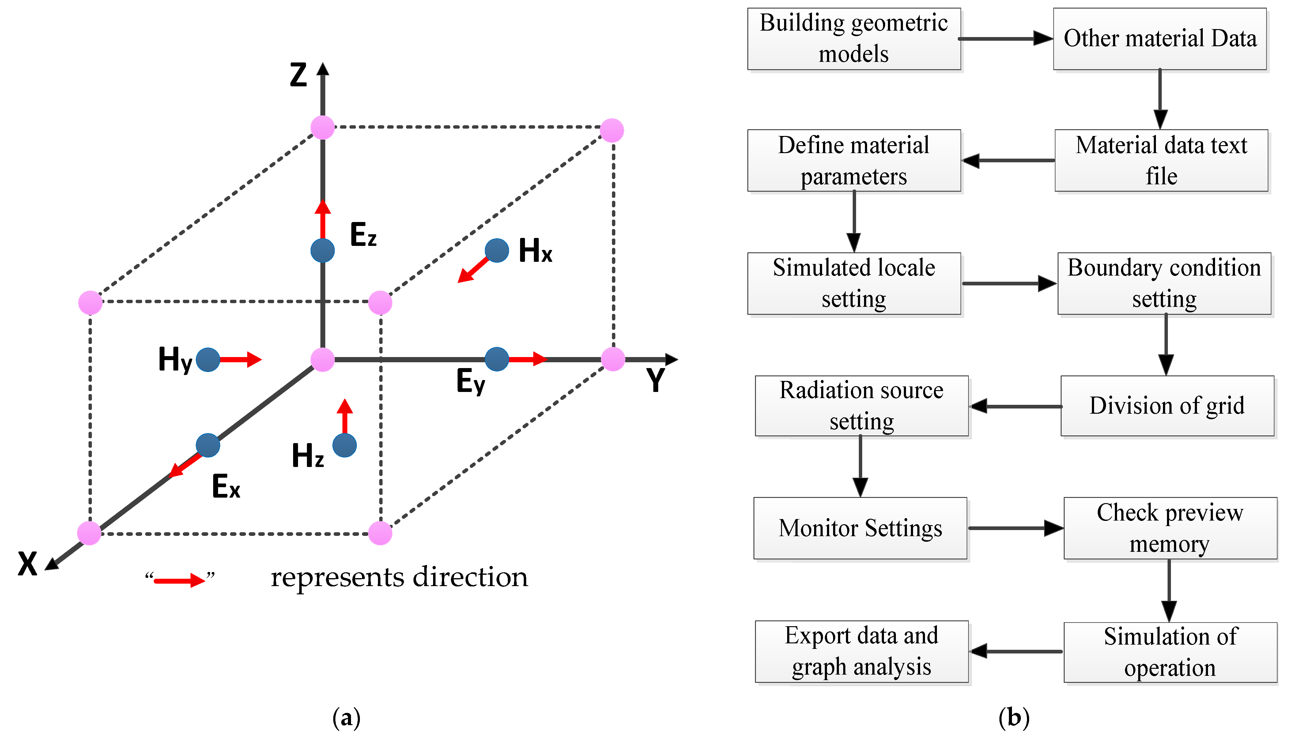
2.1. Mechanisms of the FDTD Method

FDTD is a discrete method that samples the E and H components of the electromagnetic field in space and time. By using this discrete method, Maxwell rotation equations with time variables are transformed into a set of difference equations, and the electromagnetic field in space is solved step by step along the time axis. The mathematical model of FDTD is as follows.
First, the generalized Maxwell equation can be expressed as:
× E = B t M
× H = J + D t
D = ρ
B = 0
where M = σ m H, J = σ e E, σ m and σ e are the permeability and electrical conductivity respectively, corresponding to the magnetic loss and electrical loss of the medium respectively.
With respect to an isotropic, uniform, lossy medium, there is a constitutive relation: D = εE, B = μH, ε = ε r ε 0 , μ = μ r μ 0 .
In the passive medium space of no charge source and current source, the wave equation of an electromagnetic wave can be derived by applying Maxwell’s equations and a simple vector operation as follows:
2 E μ   ε 2 E t 2 = 0
2 H μ   ε 2 H t 2 = 0
According to the above equations and constitutive relations, two component forms of curl equations can be obtained:
E x t = 1 ε ( H z y H y z σ e E x )
E y t = 1 ε ( H x z H z x σ e E y )
E z t = 1 ε ( H y x H x y σ e E z )
H x t = 1 μ ( E y z E z y σ m H x )
H y t = 1 μ ( E z x E x z σ m H y )
H z t = 1 μ ( E x y E y x σ m H z )
The above six differential equations constitute the basis of numerical algorithms for the interaction between electromagnetic waves and three-dimensional object structures.
FDTD divides the simulation model into discrete time and space grid-constructed cells, as shown in the Figure 1a. This method can deal with the electromagnetic scattering and radiation of objects with complex shapes and materials with an uneven medium. It has a wide range of applications in the simulation of micro- and nano-optical materials. The FDTD running flow is shown in Figure 1b.

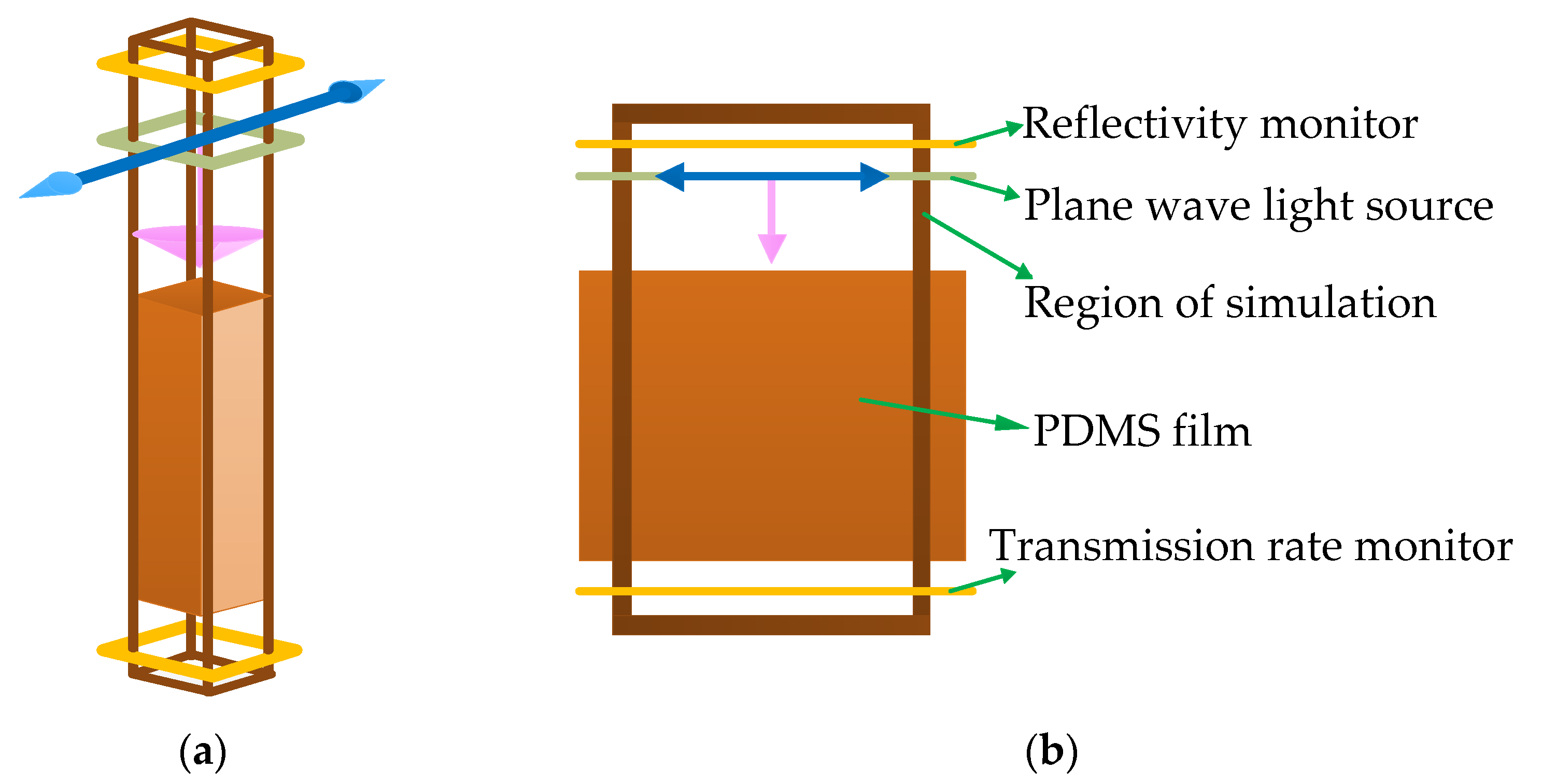
2.2. Validation of Accuracy of FDTD Method

In order to verify the accuracy of FDTD simulation, we first simulated and verified the emissivity of PDMS materials in the experiment of Zhou et al. The experimental data in this paper show that the emissivity of PDMS materials in the 8–13 μm band can reach as high as 94.6%.
The ratio of the main agent A and curing agent B of PDMS material is 10:1. Therefore, when selecting the type of PDMS material in the database, the data of refractive index n and extinction coefficient k of the material should be selected according to this ratio, as shown in Figure 2.
In the actual model, the PDMS film is 5 cm long, 5 cm wide and only 150 μm thick. Due to the uneven scale of graphics caused by the modeling of this data, the length and width of the PDMS model were set as 10 μm and the thickness as 150 μm, and the simulation area of the XY plane of its boundary could be set with periodic boundary conditions. This will not only make the graphics more coordinated, but also reduce the number of grids. Figure 3 shows the model of PDMS film.
Under the above boundary conditions, the band of the plane wave light source is 8–13 μm. The emissivity of the model was calculated according to Kirchhoff’s radiation law, and compared with the figures and data in the paper, as shown in Figure 4. Through comparison, it can be seen that in the band of 8–8.5 μm, the simulated trend is completely inconsistent with the experimental value, but it is very close to the theoretical trend of the other side. This is because there will be a drop in the initial part of the iterative calculation, and only the extinction coefficient of PDMS material at the 8–13 μm band was selected in the simulation process. However, in the 8.5–13 μm band, the simulated emissivity is almost the same as the experimental trend of Zhou, and the simulated emissivity is up to 96.5%, which is only 1.9 percentage points less than the data in the paper 94.6%. This is because compared with the simulation, the influence of clear sky weather conditions and atmospheric dust during the actual test may lead to the lower emissivity measured.
In addition, the peak emissivity of PDMS can be seen near the wavelength of 8.7 μm and 12 μm, while the effect is not optimal near the wavelength of 10.7 μm. However, on the whole, the simulation results are consistent and reliable.

3. Simulation Methods and Conclusions

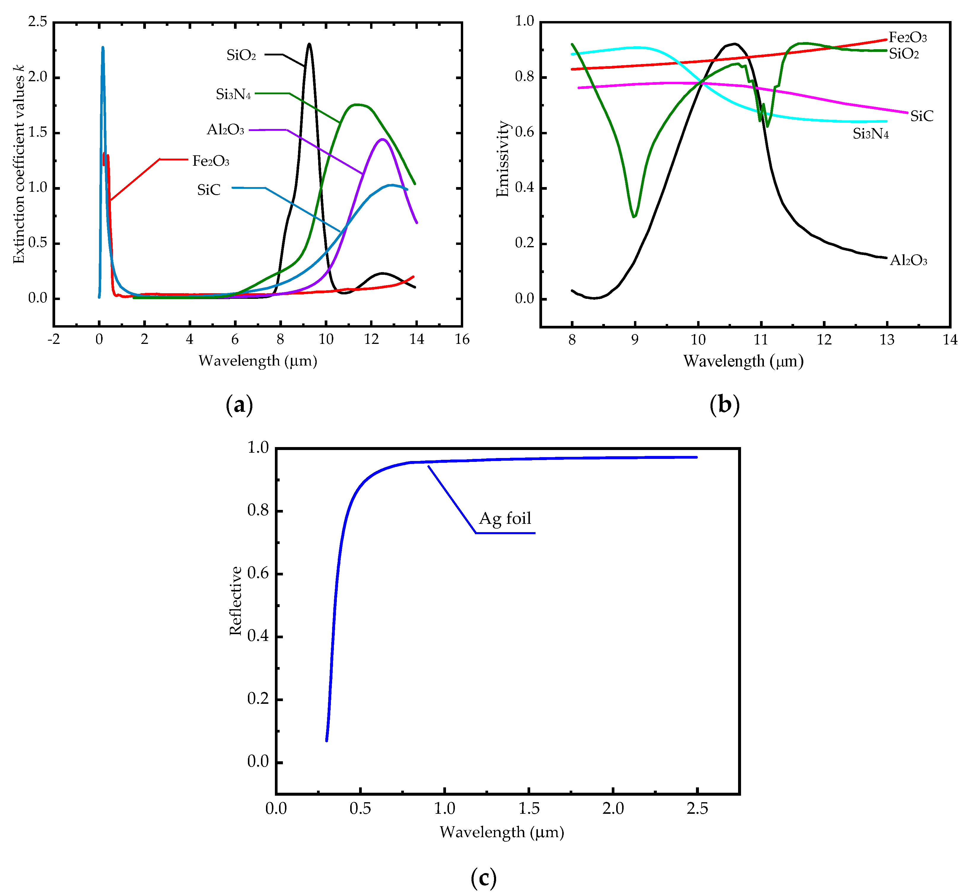
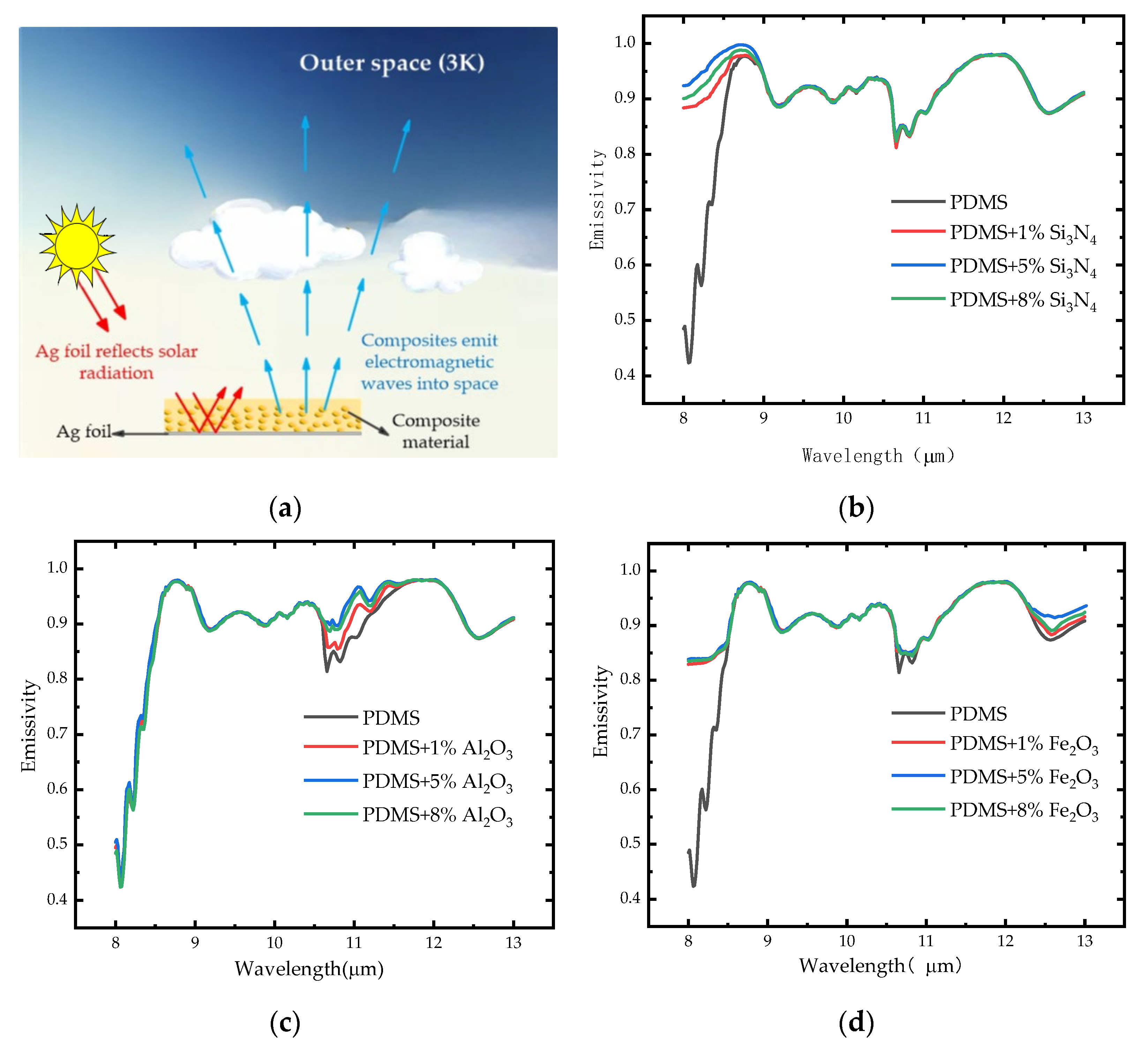
3.1. Selection of Materials

In order to make the composite material have high emissivity, some coupling or innovation is required depending on the properties of the single material. Here, SiO2, SiC, Si3N4, Al2O3 and Fe2O3 were selected to simulate the emissivity. Finally, the selected particles were integrated into PDMS film, and then the highest emissivity composites were selected by comparing the ratio of materials through simulation. In addition, the reflectance of Ag foil was also simulated.
Therefore, first of all, the emissivity of a single material was compared for the above five particles with the same thickness, and the results are shown in Figure 5b. For the reflectance simulation of Ag foil, Ag with a thickness of 200 nm is selected, because if the increase in the thickness of Ag exceeds 130 nm, it will no longer affect the reflectance. However, considering the difficulty of manufacturing 130 nm Ag foil in the actual process, Ag with a thickness of 200 nm is selected based on the consideration of the material manufacturing process and cost. Its reflectivity is shown in Figure 5c.
After the extinction coefficient of the material is obtained, as shown in Figure 5a, the optical properties of the material can be further simulated, and the emissivity of various materials in the atmospheric window band can be obtained, as shown in Figure 5b. It is clear that in the atmospheric window band, each material has a different peak. Among them, Si3N4 has a peak emissivity of 90.8% near the wavelength of 9 μm, Al2O3 has a peak emissivity of 92.1% near the wavelength of 10.6 μm, SiO2 has a peak emissivity of 91.8% and 92% near the wavelength of 8 μm and 11.6 μm, Fe2O3 has a peak emissivity of 93.6% near the wavelength of 13 μm, and SiC has an average effect. The reflectance of Ag foil to the surface solar radiation in the band 0.3–2.5 μm is shown, and it can be seen that the reflectance is basically stable at 96.4%, as show in Figure 5c.
Compared with the emissivity of PDMS material in Figure 5, Al2O3 can be selected to supplement the emissivity of PDMS material near 10.5 μm, and Fe2O3 can be selected to supplement the emissivity of PDMS material near 13 μm. In addition, it is also shown in the figure that Si3N4 has a good overall emissivity in the band 8–9.3 μm, and there is a peak emissivity near 9 μm. Therefore, Si3N4 is used to supplement the emissivity of PDMS material near 8 μm. The combination of PDMS and Si3N4 was simulated considering the comprehensiveness of the simulation, although the experimental values in Zhou’s paper [29] have shown that the emissivity of the PDMS material is better at 8 μm.

3.2. Optimization of Material Parameters

In the previous analysis, it was found that Si3N4, Al2O3 and Fe2O3 could complement the low emissivity band of PDMS materials in the 8–13 μm band. Here, we designed the simulation of the influence of different volume fractions and diameter sizes of particles on emissivity when the three materials of Si3N4, Al2O3 and Fe2O3 were mixed in PDMS materials. After selecting the best working condition, the three materials were mixed in PDMS materials at the same time, and then the optimal mixing ratio of particles was observed.

3.2.1. Optimization of Volume Fraction

Here, the influence of different volume fractions of the above three material particles on emissivity in PDMS was determined. According to the control variable method, the diameter of the three materials is 50 nm, the thickness of the PDMS material is 150 μm, and the volume fraction of the three materials is 1%, 5% and 8%, respectively. Then, the single particles with different volume fractions are mixed with the PDMS material, and a total of nine groups of simulation conditions are shown in Table 1.
The influence of the volume fraction of the three materials on the emissivity of PDMS was obtained through simulation, and the results are shown in Figure 6.
The model of PDMS film mixed with a single kind of micro- and nano-particle is shown in Figure 6a. Then, the influence of the volume fraction on the emissivity of the mixture was explored by adding different volume fractions of a single particle to the PDMS film. It can be seen that after the addition of 1%, 5% and 8% Si3N4 particles to PDMS materials, the emissivity of the mixed materials increases to a certain extent in the 8–9 μm band. It is worth noting that the emissivity of the composites does not increase with the grow of the volume fraction of the particles. Under the control of the three groups of working conditions, the emissivity of the material is the highest when the particle volume fraction is 5%, followed by 8% and 1%. When the particle volume fraction is 5%, the emissivity of the mixture reaches 99.1% at 8.7 μm. Compared with the pure PDMS material, the emissivity of the material in this band is improved by about 2% after the addition of Si3N4 particles, which is a significant change, as shown in Figure 6b. At the same time, it can be seen in Figure 6c,d that after adding Al2O3 and Fe2O3 of different volume fractions into PDMS, the emissivity of the original PDMS material in the band of 10.5–11 μm will also be improved. Importantly, after adding Al2O3, the emissivity of the original PDMS material in the band of 10.5–11 μm will be significantly improved, and the emissivity will be increased by a surprising 9.9%. The highest emissivity in this band is 97.7%. The addition of Fe2O3 also improves the emittance of PDMS film at the 12.3–13 μm band, and the emittance of PDMS film at this band is increased by 5% compared with that of pure PDMS film. It is worth noting that the optimum volume fraction of the three materials is 5%, but the emissivity will decrease when the added particles exceed a certain volume fraction. This is because, compared with the mixed material, the pure particle material will have a lower emissivity than the PDMS material. It is only because of the mixing that the emissivity of the band is increased. However, with the increase in particles, the emissivity of particles in the mixed material will account for a larger proportion, but the overall emissivity of the mixed material will decline.

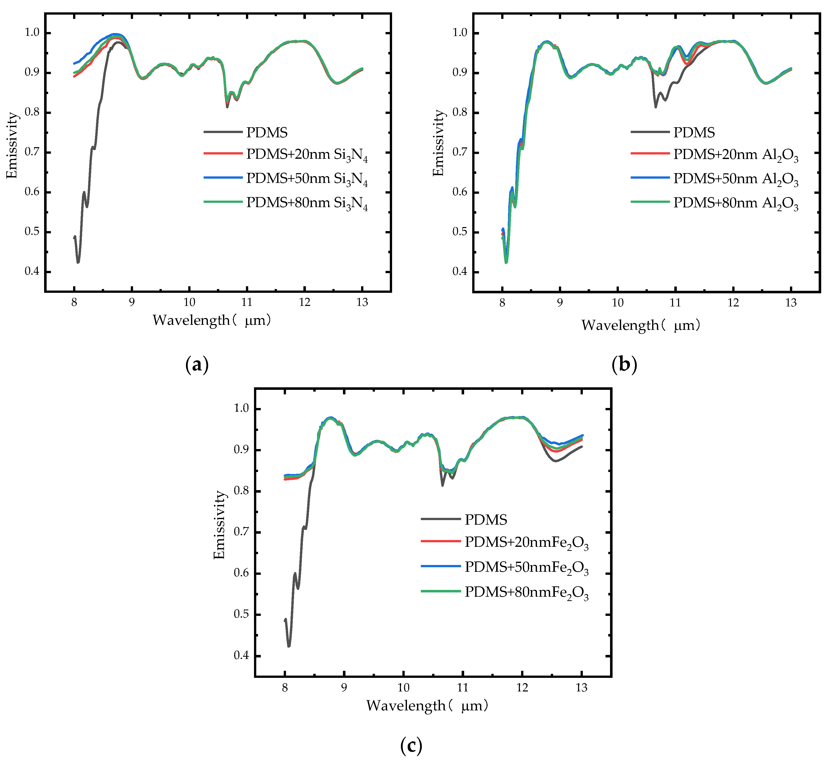
3.2.2. Optimization of Particle Diameter

In this section, the influence of different particle diameters on emissivity of each material particle in PDMS film is discussed. According to the conclusion of the previous section, the particle volume fractions are set as 5% in this section, the diameter of the three materials is 20 nm, 50 nm and 80 nm, respectively, and the thickness of the PDMS material is 150 μm. There are nine working conditions in total. The simulation scheme is shown in Table 2.
Adding different particles of different diameter with a volume fraction of 5% into PDMS thin films, the influence of the diameter of micro-nanoparticles on the emissivity was obtained, and the results are shown in Figure 7.
The thickness of PDMS film is 150 μm, in which the volume fraction of each micro-nanoparticle is 5%. When Si3N4 nanoparticles with diameters of 20 nm, 50 nm and 80 nm were added to PDMS thin films, it was found that the emissivity of the materials was very similar, and the maximum difference was only 2%. It can be seen that the influence of particle diameter on emissivity is not obvious at a certain volume fraction. However, it is worth noting that when the diameter is 50 nm, the emissivity of the mixed material is the largest, up to 99.1%, followed by 80 nm particles, and the worst effect is the diameter of 20 nm, as shown in Figure 7a. It can also be seen in Figure 7b,c that the diameter of micro-nanoparticles does not significantly improve the emissivity of the mixed material, but only weakly changes with the change of diameter. However, it can be determined from the simulation data that the emissivity of the mixed material can reach the maximum when the particle diameter is 50 nm.
Combined with the above situation, we discovered that the working parameters that significantly improved the emissivity after adding particles to PDMS were the volume fraction of 5% and the particle diameter of 50 nm.

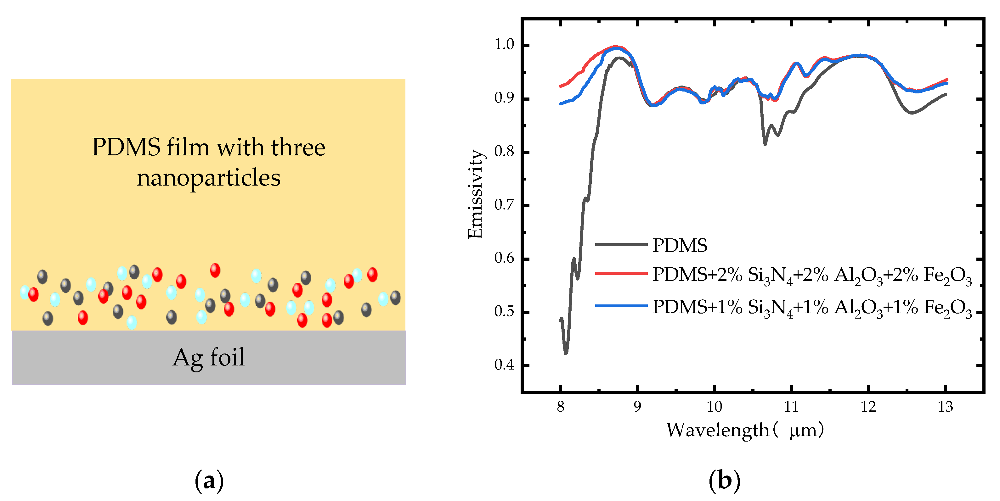
3.2.3. Optimization of Mixed Particles

In the above simulation, we obtained the influence of particle volume fraction and diameter on the emissivity of PDMS materials when a single type of particle is added to the material. However, a single kind of particles can only improve the emissivity of PDMS in a specific band. If three kinds of particles are added to PDMS materials at the same time, the low-band emissivity of PDMS materials can be theoretically supplemented, and the emissivity of mixed materials can be improved on the whole. In this section, three kinds of micro- and nanoparticles with diameter of 50 nm were mixed into PDMS film with thickness of 150 μm in different proportions to observe the influence of particle ratio on emissivity. It should be noted that the bottom of the PDMS is covered with 200 nm thick Ag foil, which is used to reflect the surface solar radiation of the 0.3–2.5 μm band, thus achieving a greater degree of radiative cooling.
Here, according to previous studies, it is found that the optimal volume fraction of a single particle is 5%, and with the increase in volume fraction, the emissivity of the material will decrease. Therefore, the volume fraction of mixed particles should not be too large, otherwise it will affect the emissivity of the whole material. In order to distribute particles more evenly, the overall integral number of the three particles is 3% and 6%; namely, the volume fraction of a single particle is 1% and 2%. Such a distribution can make the ratio of particles more uniform. Although the overall integral number of the second scheme exceeds 5%, it is close to 5% on the whole and is more uniform. Therefore, the distribution scheme shown in Table 3 is designed.
The result shown in Figure 8 can be obtained by mixing the same proportion of particles into the PDMS film.
Figure 8a shows the model diagram of the mixed material with 200 nm thick Ag foil as the reflection layer and 150 μm thick PDMS film with Al2O3, Fe2O3 and Si3N4 nanoparticles as the emission layer. The diameter of the three micro-nanoparticles is 50 nm. The total volume fraction of the particles is 3% and 6%, corresponding to the two cases where the volume of the three particles is 1% and 2% respectively. Figure 8b shows the comparison between the emissivity of the material after adding the mixed particles with 3% and 6% volume fraction respectively and that of the original PDMS material. It can be seen in Figure 8b that when three kinds of particles are added, the emissivity of the mixed material increases significantly at the 8–9 μm band, 10.5–11.7 μm band and 12.3–13 μm band. The emissivity at the 8.7 μm wavelength increased by 2.4% from 96.3% to 99.1%. At the wavelength of 10.6 μm, the emissivity increases the most, from 81.4% to 90.4%, reaching a maximum increase of 9%; at the wavelength of 11 μm and 11.4 μm, the emissivity peaks reach 96.7% and 97.7%. For the 12.3–13 μm band, the emissivity increases from 87.3% to 91.7% at 12.5 μm, achieving the greatest improvement. On the whole, the addition of three kinds of particles makes the overall emissivity of PDMS material experience a surprising improvement, and the average emissivity of the emission layer is 94.2%.

4. Discussion

In summary, a new daytime radiation cooling material based on Ag foil as the reflection layer and mixed with Si3N4, Al2O3 and Fe2O3 nanoparticles as the emission layer of PDMS thin film is proposed. The composite material can effectively reflect the solar radiation in the band of 0.3–2.5 μm near the ground surface, and can have surprising emission in the band of the atmospheric window of 8–13 μm. The highest emissivity of the material can reach 99.1%, which is a very impressive emissivity at present. The overall emissivity of the material in the specific band is clearly improved, and its average emissivity is maintained at 94.2%. This will also allow the material to use its properties to reduce the temperature of the covering in direct sunlight, resulting in truly energy-free, green and energy-saving work. Although this work is only carried out by using simulation software, it has a positive reference. In the later stage, the research on this material will be put into actual experimental demonstration. For the research on daytime passive radiation cooling, it is still important to explore the research and development of more materials and innovation. In the future, the study of materials with extremely high emissivity and reflectivity will be of great significance to the research of daytime radiation cooling.

5. Conclusions

In conclusion, a new kind of PDRC material is obtained by combining the emission layer made of PDMS mixed with nanoparticles with the reflection layer made of Ag foil. The new material achieves excellent performance with high emissivity and high reflectivity, and it can reach a solar transmissivity of 96.4% and a “sky window” mean emissivity of 94.2%. Through simulation, the following conclusions are obtained.
(1) The study on different conditions of adding single nanoparticles in PDMS films shows that compared with the diameter conditions, the change of the volume fraction of micro-nanoparticles has a more significant effect on the material emissivity, and the optimal particle diameter is 50 nm and the optimal particle volume fraction is 5%.
(2) The emissivity of PDMS film at 8~9 μm, 10.5~11.7 μm and 12.3~13 μm can be improved by adding Si3N4, Al2O3 and Fe2O3 into PDMS film, and the emissivity of the composites is higher and more uniform.
(3) The emissivity of the new material with Ag substrate and PDMS film mixed with three kinds of particles as the emission layer will reach 94.2% in the atmospheric window band, and the maximum emissivity can reach 99.1%. The reflectance of the composite material to solar radiation is also very considerable, and overall can reach about 96%, and up to 96.4%.
Despite the amazing achievements made in the recent years in PDRC, substantial challenges remain for the broad application of this technology. First of all, climatic factors play an important role in the cooling performance of PDRC. The transparency of the atmospheric window will be weakened by clouds and high humidity, which will reduce the cooling performance of the PDRC. Therefore, there will be some difficulty and space to explore the wide application of this technology in cities with high humidity and coastal areas. Secondly, sufficient physical, optical and chemical stability is a must for cooling materials. PDRC materials are mostly used in outdoor environments. Materials need to be blown through the wind, direct sun and rain while maintaining their cooling properties. This is a considerable challenge and requires further exploration. In addition, the cooling material and cooling system of PDRC also face an important problem. After a period of outdoor work, the surface will be covered by dust and dirt, which will seriously affect the performance of the cooling material. Therefore, it is necessary to develop self-cleaning or anti-pollution properties for new PDRC materials in the future. Overall, although PDRC has developed significantly in recent years, it will be necessary to address the above challenges in the coming years to meet practical applications and expand the scope of PDRC.

Author Contributions

Investigation, X.D. and J.W; data curation, T.M. and J.W.; visualization and writing original draft preparation, T.M.; project administration, X.D.; funding acquisition, J.W. and X.D.; resources, X.D.; supervision, S.L., Z.S. and X.X. All authors have read and agreed to the published version of the manuscript.

Funding

This research was funded by the Key Program of the National Natural Science Foundation of China, grant number 52130607, the Science and Technology Program of Gansu Province, grant number 21JR7RA262, the Double First-Class Key Program of Gansu Provincial Department of Education, grant number GCJ2022-38 and the 2022 Gansu Provincial University Industry Support Plan Project, grant number 2022CYZC-21.

Conflicts of Interest

The authors declare no conflict of interest.

References

  1. Wang, Y.-R.; Hessen, D.O.; Samset, B.H.; Stordal, F. Evaluating global and regional land warming trends in the past decades with both MODIS and ERA5-Land land surface temperature data. Remote Sens. Environ. 2022, 280, 113181. [Google Scholar] [CrossRef]
  2. Matthews, H.D.; Wynes, S. Current global efforts are insufficient to limit warming to 1.5 °C. Science 2022, 376, 1404–1409. [Google Scholar] [CrossRef]
  3. Goldstein, E.A.; Raman, A.P.; Fan, S. Sub-ambient non-evaporative fluid cooling with the sky. Nat. Energy 2017, 2, 17143. [Google Scholar] [CrossRef]
  4. Chen, G.; Wang, Y.; Qiu, J.; Cao, J.; Zou, Y.; Wang, S.; Jia, D.; Zhou, Y. A facile bioinspired strategy for accelerating water collection enabled by passive radiative cooling and wettability engineering. Mater. Des. 2021, 206, 109829. [Google Scholar] [CrossRef]
  5. Zeng, S.; Pian, S.; Su, M.; Wang, Z.; Wu, M.; Liu, X.; Chen, M.; Xiang, Y.; Wu, J.; Zhang, M.; et al. Hierarchical-morphology metafabric for scalable passive daytime radiative cooling. Science 2021, 373, 692–696. [Google Scholar] [CrossRef] [PubMed]
  6. Qureshi, Z.A.; Al-Omari, S.A.B.; Elnajjar, E.; Al-Ketan, O.; Al-Rub, R.A. Architected lattices embedded with phase change materials for thermal management of high-power electronics: A numerical study. Appl. Therm. Eng. 2023, 219, 119420. [Google Scholar] [CrossRef]
  7. Al-Omari, S.A.B.; Qureshi, Z.A.; Elnajjar, E.; Mahmoud, F. A heat sink integrating fins within high thermal conductivity phase change material to cool high heat-flux heat sources. Int. J. Therm. Sci. 2022, 172, 107190. [Google Scholar] [CrossRef]
  8. Al-Omari, S.A.B.; Qureshi, Z.A.; Mahmoud, F.; Elnajjar, E. Thermal management characteristics of a counter-intuitive finned heat sink incorporating detached fins impregnated with a high thermal conductivity-low melting point PCM. Int. J. Therm. Sci. 2022, 175, 107396. [Google Scholar] [CrossRef]
  9. Zhang, Q.; Wang, S.; Wang, X.; Jiang, Y.; Li, J.; Xu, W.; Zhu, B.; Zhu, J. Recent progress in daytime radiative cooling: Advanced material designs and applications. Small Methods 2022, 6, 2101379. [Google Scholar] [CrossRef]
  10. Chan, Y.H.; Zhang, Y.; Tennakoon, T.; Fu, S.C.; Chan, K.C.; Tso, C.Y.; Yu, K.M.; Wan, M.P.; Huang, B.L.; Yao, S.; et al. Potential passive cooling methods based on radiation controls in buildings. Energy Convers. Manag. 2022, 272, 116342. [Google Scholar] [CrossRef]
  11. Cheng, Z.; Wang, F.; Wang, H.; Liang, H.; Ma, L. Effect of embedded polydisperse glass microspheres on radiative cooling of a coating. Int. J. Therm. Sci. 2019, 140, 358–367. [Google Scholar] [CrossRef]
  12. Sun, J.; Wang, J.; Guo, T.; Bao, H.; Bai, S. Daytime passive radiative cooling materials based on disordered media: A review. Sol. Energy Mater. Sol. Cells 2022, 236, 111492. [Google Scholar] [CrossRef]
  13. Chen, M.; Pang, D.; Chen, X.; Yan, H.; Yang, Y. Passive daytime radiative cooling: Fundamentals, material designs, and applications. EcoMat 2022, 4, e12153. [Google Scholar] [CrossRef]
  14. Chen, J.; Lu, L. Development of radiative cooling and its integration with buildings: A comprehensive review. Sol. Energy 2020, 212, 125–151. [Google Scholar] [CrossRef]
  15. Wang, Z.; Kortge, D.; Zhu, J.; Zhou, Z.; Torsina, H.; Lee, C.; Bermel, P. Lightweight, passive radiative cooling to enhance concentrating photovoltaics. Joule 2020, 4, 2702–2717. [Google Scholar] [CrossRef]
  16. Ishii, S.; Dao, T.D.; Nagao, T. Radiative cooling for continuous thermoelectric power generation in day and night. Appl. Phys. Lett. 2020, 117, 013901. [Google Scholar] [CrossRef]
  17. Zhang, X.A.; Yu, S.; Xu, B.; Li, M.; Peng, Z.; Wang, Y.; Deng, S.; Wu, X.; Wu, Z.; Ouyang, M.; et al. Dynamic gating of infrared radiation in a textile. Science 2019, 363, 619–623. [Google Scholar] [CrossRef]
  18. Cheng, Z.; Han, H.; Wang, F.; Yan, Y.; Shi, X.; Liang, H.; Zhang, X.; Shuai, Y. Efficient radiative cooling coating with biomimetic human skin wrinkle structure. Nano Energy 2021, 89, 106377. [Google Scholar] [CrossRef]
  19. Zhong, H.; Zhang, P.; Li, Y.; Yang, X.; Zhao, Y.; Wang, Z. Highly solar-reflective structures for daytime radiative cooling under high humidity. ACS Appl. Mater. Interfaces 2020, 12, 51409–51417. [Google Scholar] [CrossRef] [PubMed]
  20. Dong, Y.; Han, H.; Wang, F.; Zhang, Y.; Cheng, Z.; Shi, X.; Yan, Y. A low-cost sustainable coating: Improving passive daytime radiative cooling performance using the spectral band complementarity method. Renew. Energy 2022, 192, 606–616. [Google Scholar] [CrossRef]
  21. Gentle, A.R.; Smith, G.B. A subambient open roof surface under the Mid-Summer sun. Adv. Sci. 2015, 2, 1500119. [Google Scholar] [CrossRef]
  22. Yang, P.; Chen, C.; Zhang, Z.M. A dual-layer structure with record-high solar reflectance for daytime radiative cooling. Sol. Energy 2018, 169, 316–324. [Google Scholar] [CrossRef]
  23. Zou, W.; Luo, H.; Yang, M.; Xu, J.; Zhao, N. Biomimetic Robust All-Polymer Porous Coatings for Passive Daytime Radiative Cooling. Macromol. Rapid Commun. 2022, 2200695. [Google Scholar] [CrossRef]
  24. Hu, L.-C.; Xue, C.-H.; Liu, B.-Y.; Guo, X.-J.; Wang, J.-H.; Deng, F.-Q. Scalable superhydrophobic flexible nanofiber film for passive daytime radiative cooling. ACS Appl. Polym. Mater. 2022, 4, 3343–3351. [Google Scholar] [CrossRef]
  25. Li, T.; Sun, H.; Yang, M.; Zhang, C.; Lv, S.; Li, B.; Chen, L.; Sun, D. All-Ceramic, compressible and scalable nanofibrous aerogels for subambient daytime radiative cooling. Chem. Eng. J. 2023, 452, 139518. [Google Scholar] [CrossRef]
  26. Chae, D.; Son, S.; Liu, Y.; Lim, H.; Lee, H. High-Performance Daytime Radiative Cooler and Near-Ideal Selective Emitter Enabled by Transparent Sapphire Substrate. Adv. Sci. 2020, 7, 2001577. [Google Scholar] [CrossRef] [PubMed]
  27. Zhou, L.; Song, H.; Liang, J.; Singer, M.; Zhou, M.; Stegenburgs, E.; Zhang, N.; Xu, C.; Ng, T.; Yu, Z.; et al. A polydimethylsiloxane-coated metal structure for all-day radiative cooling. Nat. Sustain. 2019, 2, 718–724. [Google Scholar] [CrossRef]
  28. Li, P. Preparation and Properties of SiO2/SiC Composite Film by Radiation Refrigeration; Beijing University of Chemical Industry: Beijing, China, 2020. [Google Scholar] [CrossRef]
  29. Wang, Y. Numerical Simulation of Thermal Radiation Characteristics of SiO2 Ceramic Fiber Fabric Based on FDTD Method; Harbin University of Science and Technology: Harbin, China, 2022. [Google Scholar] [CrossRef]
Figure 1. (a) Schematic diagram of FDTD method; (b) FDTD running flowchart.
Energies 16 01832 g001
Figure 2. Refractive index n and extinction coefficient k of PDMS material.
Energies 16 01832 g002
Figure 3. Model of PDMS film. (a) 3D modeling diagram for PDMS materials; (b) XZ interface coordination scale with “zoom extent”.
Energies 16 01832 g003
Figure 4. The experimental value and theoretical value in Zhou’s paper [29] compared with the simulated emissivity value of the FDTD method.
Energies 16 01832 g004
Figure 5. Properties of different materials. (a) Extinction coefficients of different materials; (b) emissivity of different materials at atmospheric window bands; (c) reflectance of Ag foil in the band 0.3–2.5 μm.
Energies 16 01832 g005
Figure 6. Emissivity of PDMS after adding particles with different volume fractions: (a) Schematic diagram of radiant cooling process of composite materials; (b) emissivity of PDMS materials mixed with different volume fractions of Si3N4; (c) emissivity of PDMS materials mixed with different volume fractions of Al2O3; (d) emissivity of PDMS materials mixed with different volume fractions of Fe2O3.
Energies 16 01832 g006
Figure 7. Effect of different diameter particles on emissivity of PDMS films: (a) influence of Si3N4 particle diameter on emissivity; (b) influence of Al2O3 particle diameter on emissivity; (c) influence of Fe2O3 particle diameter on emissivity.
Energies 16 01832 g007
Figure 8. Mixed particles of different proportions were added to PDMS films. (a) Schematic diagram of PDMS material with three particles added on Ag foil base; (b) influence of different proportions of mixed particles on emissivity.
Energies 16 01832 g008
Table 1. Different volume fractions of different particles are added to PDMS.
NumberVSi3N4/vol%VAl2O3/vol%VFe2O3/vol%Thickness of PDMS (μm)
11%1%1%150
25%5%5%150
38%8%8%150
Table 2. Different diameter of different particles are added to PDMS.
NumberSi3N4/(nm)Al2O3/r (nm)Fe2O3/r (nm)Thickness of PDM (μm)
1202020150
2505050150
3808080150
Table 3. The design of mixing particles in proportion.
NumberVSi3N4/vol%VAl2O3/vol%VFe2O3/vol%Thickness of PDMS (μm)/Ag foil (nm)
1111150/200
2222150/200
Disclaimer/Publisher’s Note: The statements, opinions and data contained in all publications are solely those of the individual author(s) and contributor(s) and not of MDPI and/or the editor(s). MDPI and/or the editor(s) disclaim responsibility for any injury to people or property resulting from any ideas, methods, instructions or products referred to in the content.

