1. Introduction
The world’s quest for clean, green, and sustainable energy is unending, partly due to the continued increase in the establishment of heavy industries across the globe and recent revolution in the technological space, which has brought about a sharp rise in global demand for energy consumption [
1,
2,
3,
4]. Environmental experts are very much concerned about global warming due to the constant emission of toxic gases to the atmosphere caused by the nonrenewable source of energy generation [
5,
6,
7]. This has necessitated several steps toward the inclination for other renewable-energy sources to keep the environment clean, sustainable, and safe for humanity. Various forms of renewable energy sources are readily available today [
8,
9], which mainly depend on environmental factors, such as the availability of sunlight for solar panels, wind for wind turbines, and tidal waves for hydro-turbines [
10]. This has significantly affected their efficiency and reduced their working capability. Most renewable-energy sources are intermittent, opening spatial and temporal gaps between energy availability and its end-users [
11]. Researchers have invested a lot of effort over the years to develop and improve most of these sustainable energy generation devices to better suit environmental conditions. These challenges might have been reduced, but they remain a significant threat to the overall working capabilities of renewable-energy sources [
12]. Although there has been huge advancement and transformation in the renewable-energy sector, environmental uncertainties remains a stumbling block to achieving its full potential. The need to also conserve natural resources reanimate much interest in other sources of alternative energy generation and storage devices, such as the fuel cells for electrochemical energy generation, supercapacitors, batteries, and other forms of energy appliances used for energy storage [
13,
14]. However, since the valuable electric energies generated by renewable sources are difficult to apply continuously and stably, energy-storage systems are needed to improve renewable energy’s utilization rate and stability. Thus, these will increase operational complexity, and using fuel cells as electrochemical generators can help mitigate this complex issue [
15]. There is also the need to develop a system that is free from environmental constraints, affordable, clean, and sustainable [
16,
17].
Advanced research into nanostructured materials will provide new technical solutions that will contribute massively to developing alternative energy sources and help improve the already known electrochemical systems (e.g., fuel cells) for electrical energy generation [
18,
19]. Nanostructured materials are intermediary structural components that lie between atomic and molecular-sized materials [
20,
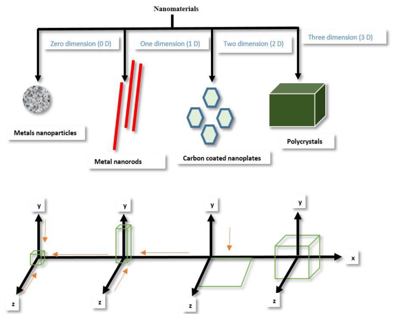
21]. The volume to dimension ratio of nanostructured materials is the most critical factor used to define the nature and characteristics of nanomaterial. They are either 0D (cluster, single atom, etc.), 1D (nanowire, nanorod, nanotube etc.), 2D (graphene, transition-metal dichalcogenides) and 3D (nanoparticle, nanoflower, etc.) [
22,
23]. Nanomaterials differ from other materials due to their novel-size characteristics and large volume to surface-area ratio. It is unanimously agreed that the novel physiochemical properties of nanostructured materials depend largely on their size, shape, and morphologies [
24]. The bandgap and wavelength of an intrinsic semiconductor increase because of quantum-size confinement. This happens when its dimensional characteristic is changed or reduced to the barest minimum. Recent high interest in nanostructured materials arises from their novel characteristics, which include quantum effect and large surface area to volume ratio [
23,
24].
Various synthetic techniques have dominated the discovery of nanostructured materials. Over the years, many methods have been put forward for synthesizing, packaging, and assembling nanostructured materials into tunable forms for various energy and medical applications [
8,
12]. This process of amending nanomaterials into various forms can be realized through a process called nanoarchitectonics [
12,
13,
25]. This process combines nano-engineering technology with methodology techniques in a specific area of interest to enhance working-material production that satisfies the characteristic of nanoscience [
12]. Nanoarchitectonics is a unique technology that gives room for the arrangement of nano-sized materials into various structural units. These usually are a set of atoms or molecules assembled in the desired composition. Nanoarchitechonics consists of two main techniques, which are nano-creation and nano-organization. Nano-organisation is the arrangement of the structural unit in a defined pattern. At the same time, nano-creation is a process through which new nanomaterials that do not exist in nature are synthesized or formed [
18]. It should be noted that nano architectonics is not limited to nano-creation and nano-organization; instead, its techniques are employed to understand the ultimate functions of nanostructured materials.
The intensity of research on nanomaterials has led to a massive breakthrough in various synthesis methods. A wide range of nanomaterials can now be synthesized with reasonable control over size, shape, and morphology [
26]. While some nanomaterials can be synthesized via a single-step approach, others will need multiple steps approaches for their synthesis [
27]. The internal architectural formation of a nanostructure is a crucial factor in its performance, and this factor varies greatly depending on the application for which the nanostructure was designed [
20,
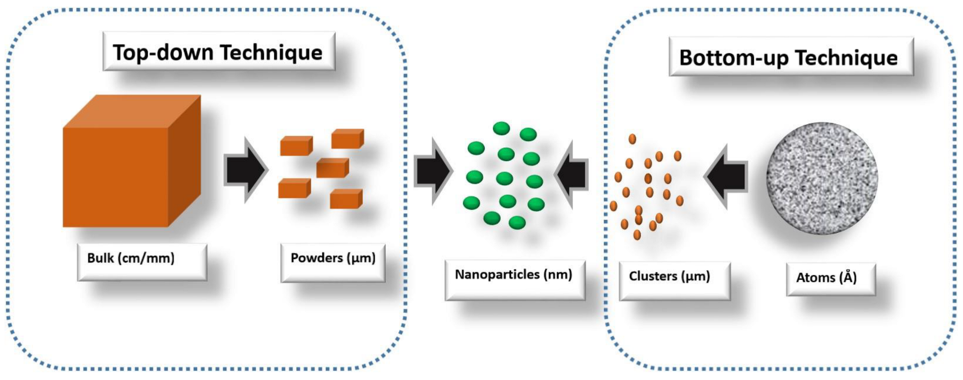
27]. Top-down and bottom-up synthesis technique can be used to synthesize nanostructured materials [
28]. The two approaches differ uniquely in the mode of preparation, but all have the same end product of a novel nanostructured material.
The top-down method involves a descending order mode of preparation, which simply means the initial raw materials are bulk. These bulk materials are broken down to obtained nanomaterials. This can be achieved through several processes such as grinding, milling, crushing, attribution [
28,
29,
30]. This method brings about a high yield of nanomaterials but requires specialized skills and expensive equipment that experts must handle during the synthesis to ensure that parameters, such as high temperature and pressure needed, are maintained. One should bear in mind that nanostructured materials obtained through this method usually contain some contamination and are non-uniform in shape. In addition, they have a surface defect, which are parts of the demerit associated with this method [
2,
31]. This technique is not recommended for nanostructured-electrocatalysts synthesis, as controlling the size and shape of nanomaterials has proven to be difficult using this method of production.
The bottom-up synthesis method involves an ascending-order mode of raw-material preparation. This simply means nanomaterials are made from tiny materials, such as atoms, clusters, particles, or tiny organic molecules [
27]. These constituent materials combine readily and form complex nanostructured materials. The bottom-up technique has many merits, such as cheap equipment used during the synthesis process, being readily available, easy to carry out, low energy consumption, ability to reproduce easily, and the theoretical probability of controlling the morphology, dimension, and mono-disparity of the nanoparticle [
32]. This technique is predominantly used for nanomaterial fabrication due to its numerous advantages over the top-down approach. Doping of material using this method ensures precursory selectivity when compared with the top-down approach, which depends very much on bulk-material homogeneity. In the bottom-up approach, the shape of the synthesized nanostructured material is partly determined by the seeds’ nucleation and kinetic growth [
33]. The shape and size of nanocrystals can be controlled by altering parameters of analytic reaction, such as precursor temperature, surface surfactant concentration, and time in crystal-nucleation-growth phases [
34]. Though this technique also has its own demerit, it has proven to be more successful when used in nanostructured-electrocatalyst synthesis, unlike the top-down approach, which is majorly not suitable for electrocatalyst synthesis. Both methods are illustrated in
Figure 1 and
Figure 2, respectively.
The main factor in manipulating the morphology of nanomaterials is to understand their primary mechanism of formation. This mechanism is defined by the classical Ostwald ripening, in which larger nanoparticles outgrow smaller ones to ensure a reduction in surface energy [
35]. The formation of spherical nanocrystals is commonly described as occurring due to this phenomenon.
An electrocatalyst is a type of catalyst that alters the rate of an electrochemical reaction on an electrode surface. It is of utmost importance to understand the kinetics of electrocatalysts in fuel cells, as this holds the future for a sustainable, clean, and green energy society. Fossil fuel will also be conserved through improved electrochemical devices, bringing about a serious and drastic decrease in fossil fuel dependence. Examining the methanol-oxidation mechanism on a platinum electrode will result in the emergence of an intermediate carbon monoxide, which acts as a poison to the Pt electrocatalysts in DMFCs. The introduction of Co (cobalt), an oxophilic metal, can effectively remove the intermediate CO (carbon monoxide) poison formed [
27,
36,
37]. Equations (1)–(4) describe the reaction process.
The catalyst that takes part in an electrochemical process is known as the electrocatalysts. This category of catalysts can be synthesized by skillfully arranging nanostructured materials to create a more readily active catalyst that can be used in the electrocatalysis of energy devices requiring electrochemical reactions [
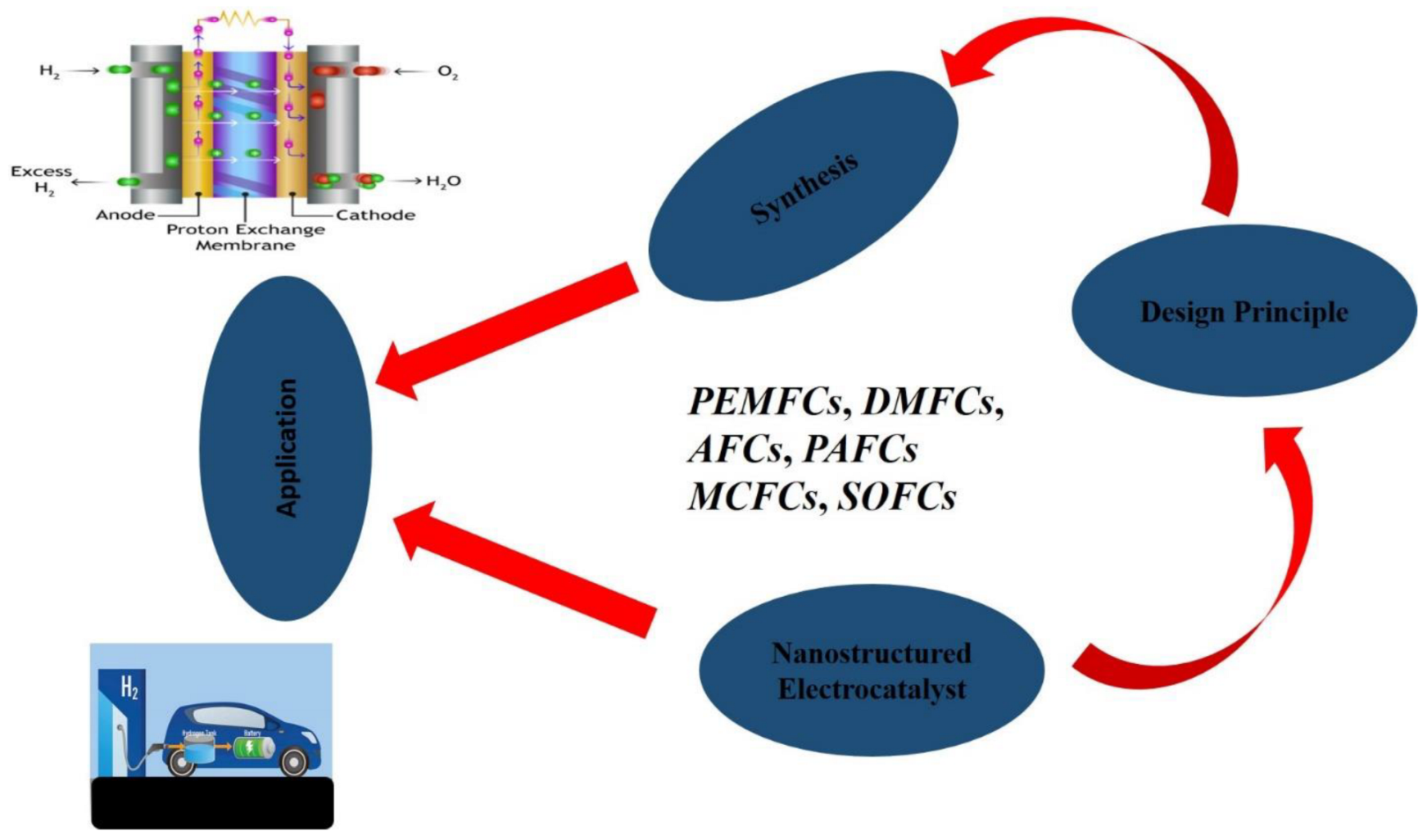
38]. Several electrocatalysts have been developed recently, which are made from a platinum group of metal to a carbon-based electrocatalyst for fuel cells. This paper attempt to summarize previous studies on the use of novel nanomaterial electrocatalysts for fuel cells and recommended the new electrocatalysts for future applications. Holistic effort was dedicated by the authors to ensure that most of the literature reviewed were from the last five years and are relevant to the existing challenges confronting the application of nanostructured-electrocatalysts materials in fuel cells. An outline of the topic discussed is illustrated in
Figure 3.
2. Design and Application of Nanostructured Electrocatalysts in Fuel Cell Devices
A highly effective and rational design of a nanostructured-electrocatalyst material is of high importance to a sustainable electrochemical-energy system. When a nanostructured electrocatalyst material is designed at a nanoscale dimension, it should provide benefits, such as short pathways for charge transport, good accommodation of strain electrode arising from the electrochemical reaction, and not allowing new reactions with mass material [
39,
40]. The use of nanotechnology to improve sustainable-energy conversion is of great importance. The fuel-cell technology is a sustainable energy-conversion system that relies on electrochemical reactions to produce electrical energy [
41,
42,
43]. Nanostructured materials have brought many ways through which fuel-cell technology can be improved. The introduction of nanostructured electrocatalysts will bring about a rapid increase in the efficiency of fuel-cell technology [
44]. This paper summarizes some of those benefits, their importance, the knowledge gap, and the way forward. Energy conversion in fuel cells involves chemical interaction at the surface or interface. Therefore, the properties of nanomaterials will play a big role in bringing about highly efficient energy conversion in fuel cells. An ideal nanostructured material that should be used for electrocatalysis will be cost-effective and possess all the following qualities [
45,
46]: high porosity, high area of contact between the electrodes and the electrolyte, high thermal and chemical stability, high ions and electron mobility, high durability, and a large surface area.
Solid oxide fuel cells (SOFCs) and molten carbonate fuel (MCF) typically operate at temperatures ranging from 500 to 1000 °C. While both proton exchange membrane fuel cells (PEMFCs) and direct methanol fuel cells (DMFCs) to operate at low temperatures (20 °C to 80 °C), DMFCs produce a low power density and utilize little methanol [
47,
48,
49]. Alkaline fuel cells (AFCs) use a low-cost electrode catalyst (Ni, Cu, Co, etc.) instead of Pt and can operate at room temperature, making them a potentially reliable and onboard energy source. The alkaline solution (KOH, NaOH) easily reacts with the carbon in the fuel, resulting in carbonate deformation, which requires pure hydrogen gas as its fuel. Currently, researchers are putting their effort into obtaining a high energy density and a good utilization efficiency with new electrocatalysts that have high catalytic ability and are cost-effective. Pt
1-xCo
x alloy of nanoparticles has shown to be a promising cathode in reducing oxygen PEM fuel Cells, with an exciting future of reduced cost and increase in oxygen reduction. Pt
0.55Co
0.45 shows the highest growth in electrochemical reaction. They have been shown to have a uniform distribution on a carbon matrix with particle sizes less than 10 nm when used as electrocatalysts [
31,
50]. The result of electrochemical testing indicates that Co presence enhanced the electrocatalytic activities and the stability of catalyst in the long term.
The Pt/Sn/PMO
12/CNT catalyst [
51] produces the lowest potentials for the electrooxidation of absorbing carbon intermediates, compared to Pt/Sn/CNT and Pt/CNT catalysis. They also produce a high current density for the oxidation of methanol at standard room temperature, compared to Pt/Sn/CNT catalyst prepared with the same method. The development of platinum (Pt)-based electrocatalysts that are both highly efficient and stable for oxygen reduction reaction (ORR) is one of the most essential steps towards the eventual commercialization of fuel cells. Due to the sufficient exposure of the active surfaces and the practicability of mass movement, highly accessible reactive surfaces play a major role in enhancing ORR for enhanced fuel-cell efficiency [
52]. This review has fully established that nanostructured electrocatalysts will enhance electrocatalytic activities in the electrochemical reaction, in which fuel cells and other energy device performances will be greatly improved.
Despite the advances in technology to date, no nanostructured material manufactured has all these qualities embedded in it. This section discusses ways through which high efficiency and stable material for fuel-cell application can be achieved, and these are based on theoretical evidence gathered from various research.
2.1. Porosity of Nanostructured Material
In a fuel cell, using porous materials will make it possible to exert great control over the surface area between the electrode and the electrolyte, while also facilitating the creation of a short diffusion path for the movement of both charge and molecules [
53]. This will ensure that the electrochemical process is as effective as possible. The nanostructured material pores’ outer surface and interior interact with the surrounding environment. Small pores can limit electrolyte-ion diffusion, resulting in a decrease in the rate of the kinetics of the reaction [
26,
34,
54]. The pore structural surface of an electrode plays an integral part in its electrocatalysis. Therefore, a highly porous material’s design is crucial for fuel cells’ electrochemical process.
2.2. High Electronic Conducting Material Should Be Assembled
Fuel cells are seriously affected by low electronic-conducting materials. Therefore, getting an improved electronic conducting and stable material are critical factors that must be considered during the design of an electrocatalyst [
46,
55,
56,
57,
58]. This will result in improved electrocatalytic performance. Improving these critical factors can result in an efficient charge transport pathway, a short diffusion time, and high electric conductivity, resulting in a good electrochemical process [
59]. The assembling of nanostructured materials with good electronic conductivity can be used to improve the performance of an electrocatalysts.
2.3. Increased Specific Surface Area
The most important factor in determining electrocatalytic properties of a catalyst is the surface structure (i.e., particular style of faceting or the prevailing crystallographic directions and planes in the catalytic material, also known as the Miller indices), not necessarily the shape of the nanocatalyst. However, some shapes are preferred as they tend to give rise to the preferred atomic arrangement for enhanced electrocatalytic activity. Thus, what some researchers believe to be shape-dependent electrocatalytic activity is simply shapes of catalysts that give the right surface structure (Miller indices) for enhanced electrocatalysis. Therefore, every study should explore the correlation between shape and surface structure, with a view to synthesizing nanocatalysts with shapes that give a preferential surface structure.
The surface impact considers not just the kinetics of the reaction but also the surface- thermal system, the surface energy, and the chemistry of the materials involved [
3,
34,
60,
61]. This considerably impacts the thermodynamics of the reaction that occurs at the interface between the electrolyte and the electrocatalyst. A small and specific surface area will impede reaction rates and cause electrocatalyst efficiency to deteriorate. Increasing the surface area will result in improved ions transport and molecular adsorption. This will also result in a better electrochemical process at the electrocatalyst’s interface of solid-gas or solid-liquid. It is critical to design and build an electrocatalyst with a large surface area for fuel-cell applications.
2.4. Percentage Increase of Active Facet Exposure
The electrocatalytic characteristics of materials with the same elements or chemical makeup, but are oriented differently, are distinct from one another. This is due to its numbers, design, and facet exposure to catalysis. While it has been demonstrated that some facets are less reactive than others, it is necessary to create nanostructured materials with adequate active-facet exposure to participate in fuel cells’ electrocatalytic process and electrochemical reactions [
42,
54,
60,
62,
63].
The enhancement of electrode material in fuel cells can be achieved through the addition of nanostructured electrocatalysts, as they ensure high catalytic activities, thereby improving the overall efficiency of the fuel cell. Enhancing the structure or using a nanostructured electrocatalysts can increase the catalytic efficiency of direct-methanol-fuel cells. Multiple studies have demonstrated that adding a suitably ordered nanoparticle array or porous network to the catalytic layers can boost Pt utilization and catalytic efficiency due to an increase in the electrochemically active surface area.
The application of nanostructured electrocatalysts can improve the electrochemical properties of various fuel cells through a proper design technique of electrode architecture. Nanostructured-electrocatalyst materials help to significantly improve reaction kinetics and thermal properties of an electrochemical reaction by ensuring high power and energy densities. In developing a synthetic technique for nanostructured materials with enhanced characteristics, the synthesis technique and operating parameters need to be thoroughly investigated, comprehended, and able to develop precise control over the morphology of the material. This review highlighted the use of nanostructured electrocatalysts in various fuel cells in
Table 1.
Table 1.
List of nanostructured electrocatalysts used in various fuel cells.
Table 1.
List of nanostructured electrocatalysts used in various fuel cells.
| Fuel Cells Type | Role of Nanostructured Electrocatalysts | Ref. |
|---|
| Polymer Electrolyte Membrane Fuel Cells (PEMFCs) | In PEM Fuel Cells, nanostructured electrocatalyst ensures high electronic-conduction pathway, homogenous dispersion of Pt-based catalyst particles, ionomer, and gas transport in porous media. The nanostructured electrocatalyst is very much helpful in Pt utilization, reduces Pt loading and helps remove carbon corrosion-induced oxidation on the cathode of Polymer Electrolyte Fuel Cells. The introduction of nanostructured electrocatalysts will enhance the sluggish kinetics of the oxygen reduction reaction (ORR), thereby bringing about fast and efficient catalytic activities in the electrodes. | [64] |
| Direct Methanol Fuel Cells (DMFCs) | The catalytic efficiency of Direct Methanol Fuel Cells can be improved by the addition of an optimized nanostructured electrocatalyst. Due to the excellent catalytic activity with respect to methanol oxidation of platinum at a low temperature in electrodes of DMFCs, nanostructured electrocatalyst has helped greatly in improving the overall efficiency of the system. They also reduce CO-poising effect and bring about high catalytic activity for methanol electrooxidation. | [57] |
| Alkaline Fuel Cells (AFCs) | Alkaline fuel cells are the most environmentally friendly of all the electrochemical energy sources. The application of nanostructured electrocatalyst results to improve kinetics at low potentials, reduce the possibility of crossover from its anodic components to the cathode side, minimize the corrosion risk for electrode material, and limit the risk of spectator-ions adsorption. The possibility of CO posing is minimal with the application of nanostructured-electrocatalyst material to the electrodes. | [38] |
| Phosphoric Acid Fuel Cells (PAFCs) | Phosphoric acid fuel cells have been successfully tested as energy-conversion technologies in stationary-energy- generation applications. The application of nanostructured- electrocatalyst material, especially the non-platinum group metals, has shown promising and encouraging immunity against surface poising by phosphate ions at room temperature. By using imaging microscopy, it was revealed that iron particles were isolated from the electrolyte of graphite layers, which ultimately protects the iron from phosphate-anion adsorption. | [65] |
| Molten Carbonate Fuel Cells (MCFCs) | MCFCs reduce high-temperature corrosion and breakdown of cell components, increase catalytic activities in the electrode, and ensure high power density. | [66] |
| Solid Oxide Fuel Cells (SOFCs) | The application of nanostructured electrocatalyst in Solid Oxide Fuel cells enhances the overall performance of the system. They increase the electrode-surface area and ensure a high oxygen- reduction-reaction rate at the electrode. | [19] |
3. Chemistry Base Synthesis Techniques
The chemical synthesis of nanostructured materials is a bottom-up method that relies on assembling or manipulating atoms and molecules to form novel nano-structural properties at the nanoscale dimension [
67]. Through atomic-level reactant mixing, this method is frequently used to prepare gels or fine co-precipitated combinations [
25]. The product of the material obtained can be converted later in a short reaction time and at a low temperature. This is due to the short dissemination distance between coarse-grind materials and convectional blending. Changes in the kinetics and thermodynamic parameters of the reactant can be used to control the shape and size of these nanoparticles [
68]. Chemical processing and preparation of nano-structural materials are still developing specialties, with several known conventional methods being reviewed and new models being put forward. This new method is intended to serve as a solid foundation for the production of inorganic, hybrid, and organic materials. Many nanoparticles have been synthesized under non-polar or polar conditions using the chemistry-based synthesis technique. Some chemical-based techniques lend themselves to mass production and commercialization. To ensure that the reaction can be reproduced, its “synthesis parameters should confirm with factors such as diffusion coefficient, surface energy, growth rate, nucleation, and separation”. There are a plethora of chemical-based synthesis techniques which this review cannot adequately capture.
3.1. Sol-Gel Synthesis Method
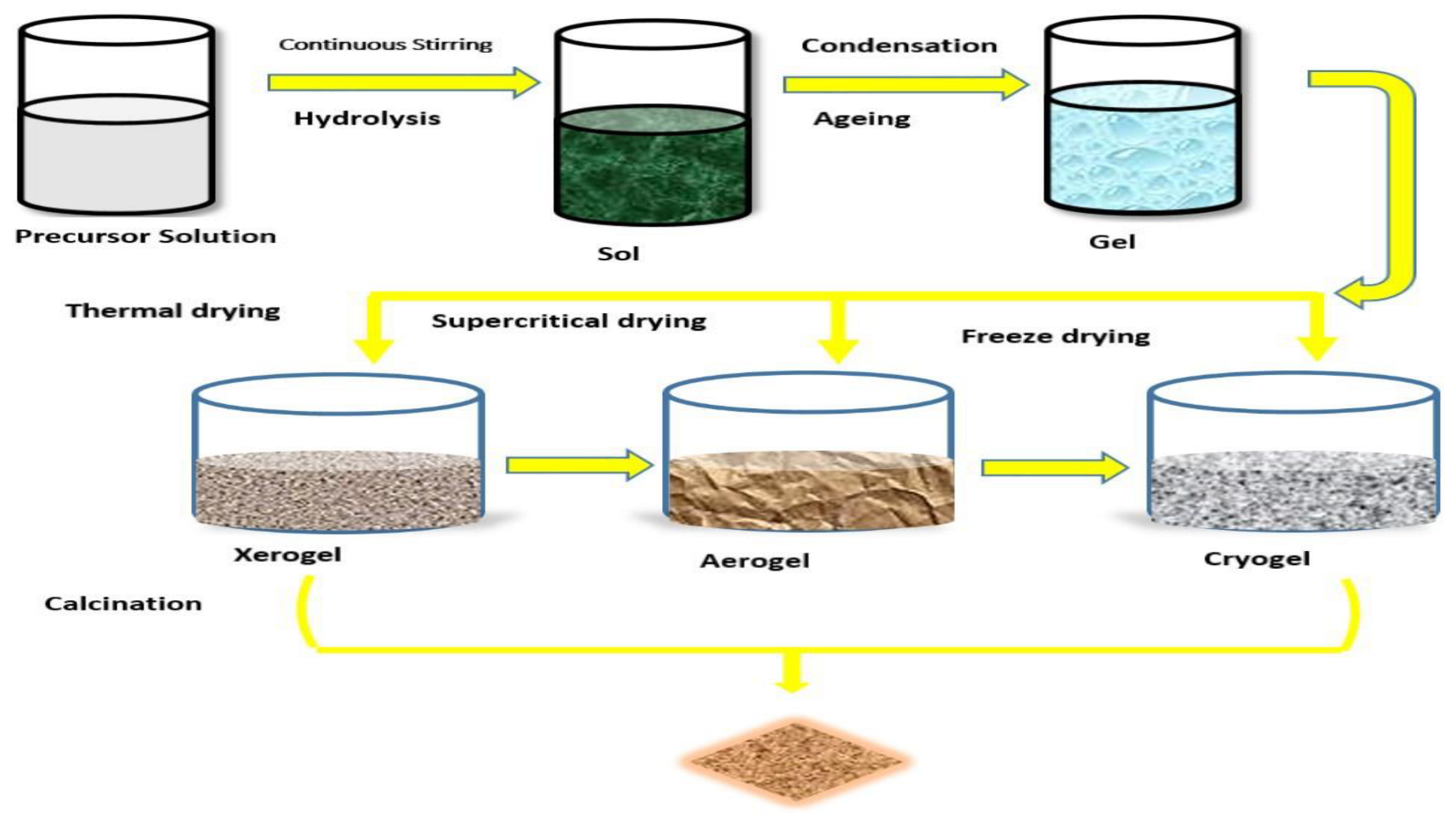
Molecules and microparticles in a molten or solution (sol) state aggregate and loop up to form a chemical-structural latticework (gel) under a defined condition. The sol-gel synthesis method is of two types: the colloidal technique and the polymeric or alkoxide route method, as presented in the
Figure 4 [
69]. Both sol-gel methods involve a precursor in an appropriate solvent but are different in the types of raw materials or reactants. The raw materials or reactants can be “inorganic or organic, liquefy in a homogeneous solution according to the designed” compound [
70]. Water is used for the colloidal-route method, while alcohol is typically used as the solvent for the plyometric route. In the presence of this solvent, the breakdown of metal alkoxide occurs in a manner that is described by the following chemical equations [
71].
The precursors become active either by introducing an acid or base to it so that it can form a sol-gel network. The equation is given below [
69].
Metal-oxo and metal-hydroxo are formed in the solution during the condensation reaction. These occur when metal centers combine with the oxo (M-O-M) and hydroxo (M-OH-M) to close the gap between two hydroxylated species via dehydration and condensation reactions. As illustrated in the equation below, this type of reaction produces a gel-diphasic system composed of solid and liquid with varying morphologies ranging from a simple particle to a polymer network [
70,
71].
With increasing temperature and time, the resulting network structures grow until the container is gradually filled to the brim. At this juncture, the viscosity of the liquid also rises until it gets to gelation. This is the point where no visible observation of liquid flow can be seen [
72]. Post refining, such as thermal decomposition and drying, may be needed for the removal of unused organic solvent. This ensures the formation of a fine crystalline with improved mechanical properties and structural stability. The following are the general rules guiding the sol-gel techniques [
73]:
- i.
Making a homogeneous solution by dissolving organic or inorganic metal salts in water or a solvent.
- ii.
Conversion of the formed solution into a sol
- iii.
Gelation
- iv.
Ageing
- v.
Drying
- vi.
Thermal heating
Solute concentration, precursor types, pH, temperature, and the kind of solute utilized during the reaction significantly impact nucleus growth, condensation reaction rate, and hydrolysis process. The condensation and hydrolysis processes are always influenced by the pH value, which influences the resulting nanoparticle structure that is formed. Slow hydrolysis and condensation will result in the formation of a small number of nanoparticles. Depending on the nanoparticle size desired during the synthesis process, this could be advantageous or disadvantageous. There is a serious need to control reactive parameters during synthesis to ensure a high and good yield. Two processes must be controlled to ensure high crystallinity, nucleation, and nuclei development of formed crystal [
74]. The system transitioning to a more metastable state is the most important factor in determining the crystal formed at the start of a new phase. Through the proper choice of precursors and reaction variables, sol-gel techniques provide many benefits, which include process simplicity, high purity, good homogeneity, low processing temperature, good control over particle size and morphology, stoichiometry control, and suitable particle structure [
75]. At the atomic level, low-temperature mixing of precursor colloidal can yield nanostructured materials with good crystallinity. Though there are several merits associated with the sol-gel techniques, it also has its own disadvantages, such as expensive precursors and, sometimes, there is the formation of amorphous material that requires heat treatment.
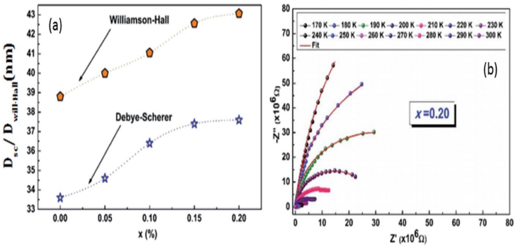
Issoli and colleagues [
76] “studied the effect of reaction parameters on the physicochemical and electrochemical properties of nanostructured materials”. They made use of temperature variation and reaction concentration of precursor as their standard variables. At the same time, the Debye Schemer technique (Equation (9)) [
76] and the Willian-Hall technique (Equation (10)) were applied for the analysis. The sizes of the crystalline formed at a variable concentration of bismuth precursor were found with the aid of an XRD machine. They discovered a significant increase in the size of crystalline formed when the bismuth concentration was increased.
The Debye-Schere equation is given below.
is the applied wavelength, is the Bragg angle with the most intense peak, and is full width at half maximum of peak diffraction.
In Williamson–Hall technique, the widening of the X-ray line (
is equal to the resulting expansion caused by lattice deformation (
strain) present in the material and the contributing crystallite size (
size).
The research also proves that nanoparticles’ grain size and porosity increase at the same rate as bismuth. Electrochemical impedance and spectroscopy were used to investigate the temperature effect on the electrical conduction of nanoparticles.
Figure 5 demonstrates the Nyquist-curve diagram of [(La
0.8Ca
0.2)]
1xBi
xFeO
3 nanostructured material, which was obtained at different temperature intervals [
77]. The Nyquist curve demonstrates that as temperature rises, the half-arc radii decrease. This clearly demonstrated that temperature has a significant impact on electrical conductivity.
In the study by Rosset et al. [
77], a supercritical-dried alloy of calcium “ZnO nanoparticles with different [Ca]/[Zn] ratios were synthesized using different precursors using the sol-gel technique”. The researchers discovered that the type of precursor used influences the crystalline size and morphology of Zn
0.90Ca
0.10 nanoparticles. This reveals that the Zn
0.90 Ca
0.10 nanoparticles that were synthesize with CaSO
4 and CaCO
3 precursors had a quasi-spherical shape and a particle-size distribution of (20–30) nm. Nanoparticles of Zn
0.90Ca
0.10 synthesized from Ca(NO
3)
2 and CaCl
2 precursors exhibit spherical or hexagonal shapes. This result proves that the precursors have a significant impact on nanoparticles’ sizes, shapes, and morphologies [
78]. Using the sol-gel synthesis technique, Dai et al. fabricated a highly porous perovskite structure arranged in a hierarchical order [
79]. Because of its high conductivity in an alkaline medium, the CaFe
0.7Zn
0.3O
3 electrocatalyst performed significantly better than platinum on carbon under alkaline conditions as compared to neutral conditions. Sun et al. created perovskite La
0.3Sr
0.6Ce
0.1Ni
0.1Ti
0.9O
3-d (LSCNT) and La
0.4Sr
0.6Ni
0.1Ti
0.9O
3d (LSNT) for use as an anode in hydrocarbon-fuel cells. An exsolved-metallic Ni provided the electrooxidation-active site, while the Ce groups provided the redox properties that were used to improve the electrochemical process by introducing more readily active oxygen ions. They also aided in the expulsion of carbonaceous species that have been accumulated on Ni.
Table 2 summarizes various synthetic approaches involved with the sol-gel technique, while
Table 3 gives the advantages and disadvantages of this technique.
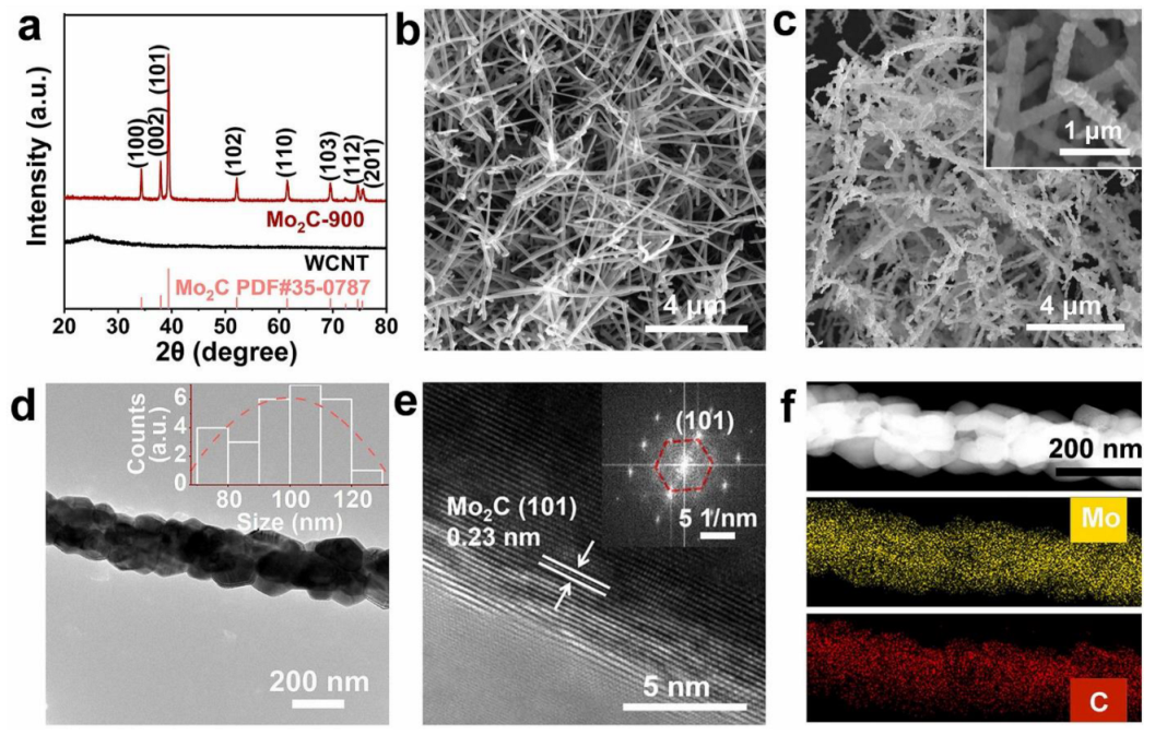
In a study by Manting Qiang and Co [
80], a facile and scalable approach was adopted to synthesise high-purity nanostructured Mo
2C electrocatalyst made up of nanocrystals. The whisker CNT was used as both template and carbon source, while the NaCl and MoO
2Cl
2 were used in generating the Mo-based precursor. During the synthesis process, the vapour of MoO
2Cl
2 precursors and in-situ CO
2 gas that were produced serve as the etching reagent. The CO
2 helped in converting solid carbon into a reductive carbon CO gas and ensured high-interfacial carbon, facilitating the formation of highly stable Mo
2C. An increase in the consumption of carbon at the Mo
2C/C interface resulted in the formation of nanostructured electrocatalysts (Mo
2C) through an interface-induced propagation-synthesis mechanism. This mechanism brings about better control of the morphology, purity, and crystallinity of Mo
2C. High-quality structure of Mo
2C nanostructured electrocatalyst was observed via scanning electron microscope (SEM) and transmission electron microscopy (TEM) analyses. The synthesised Mo
2C shows excellent stability and HER characteristics that are required for nanostructured-electrocatalyst application in fuel cells.
Figure 6 shows the structural and morphological analysis of the Mo
2C electrocatalyst.
Table 2.
Summary of various synthetic approaches involved in the sol-gel technique.
Table 2.
Summary of various synthetic approaches involved in the sol-gel technique.
| Nanomaterials | Precursors | pH-Balance | Condition for Synthesis | Drying/Gel Formed | Size of Particles | Ref |
|---|
| MnFe2O4NPs | Mn(NO3)2·4 H2O, Fe (NO3)2, citric acid. | NaOH | Heated to temperatures ranging from 0 to 70 °C, evaporated to form a gel, dried to form flakes, and calcined for 2 h at 900 °C in a nitrogen atmosphere. | - | 45 nm | [81,82] |
| Cd2V2O7 NPs | Cd(NO3)2·4 H2O, NH4VO3, citric acid. | - | Stirred for 2 h at 100 °C, evaporation formed gel, dried in an oven at 80 °C, calcined for 2 h at various temperatures. | - | (10–20) nm | [83] |
| Al doped ZnO NPs | Zn(CH3COO)2·H2O, Al (NO3)3, methanol. | NAOH | Stirred 90 min, stirred 60 min after pH balancing, centrifuged 20 min at 10,000 rpm, washed, dried 2 h at 60 degrees Celsius, and calcined 2 h at 200 °C. | - | (20–50) nm | [84] |
| Bismuth ferrite NPs | Bi (NO)3·5 H2O, ethylene glycol, Fe (NO)3.9 H2O | - | Stirred for 2 h, heated to 60 degrees Celsius, and calcined for 4 h at 500 °C. | Evaporation/Xerogel | | [85] |
| CuO NPs | Cu(NO3)2·3 H2O, citric acid | - | Stirred at 90 °C until gel formed, then heated to 100 °C and annealed for 2 h at various temperatures of 200 °C, 300 °C, 400 °C, 500 °C, and 600 °C. | - | | [86] |
| ZnO NPs | ZnAc2, 2 H2O | NAOH | The precipitate was centrifuged, washed, and dried by lyophilization after being heated to temperatures ranging from 0 to 80 °C. | Freezing/Cry ogel | 37 nm | [87] |
| Co3O4 NPs | Cobalt acetate, polyvinylpyrrolidone (PVP), tri-ethanol | - | Stirred for 30 min, heated for 2 h at 300 °C, and annealed for 3 h at 450 °C. | - | 50 nm | [88] |
| Cu doped TiO2NPs | Titanium butoxide (C16H36O4Ti), copper acetate (Cu(CH3COO)2), HCl, methanol, ethanol | - | Stirred for 2 h at 50 °C, then annealed at 400 °C. | | | [89] |
| Fe doped TiO2 NPs | Iron (III) chloride 6-hydrate, C2H28O4Ti, ethanol, citrate acid, C5H8O2 | - | Stirred at 40 °C, refluxed at 120 °C for 6 h, gel obtained by heating 14 h at 80 °C, drying at 150 °C for 1 h, and annealing 1 h at 400 °C, 600 °C, and 800 °C. | Supercritical/Aerogel | (6–11) nm, (22–30) nm, (50–100) nm | [90] |
Table 3.
Advantages and disadvantages of sol-gel techniques.
Table 3.
Advantages and disadvantages of sol-gel techniques.
| Advantages | Disadvantages |
|---|
| They are cost-effective. | Organic chemicals present some health challenges. |
| They have a low processing temperature. | The reaction takes a longer time. |
| The technique is simple in making nanostructure and nanocomposites. | Purification of sample brings about post-treatment. |
| They have high purity. | |
| A modest amount of dopant is allowed into the sol, whose presence can be felt in the final product. | |
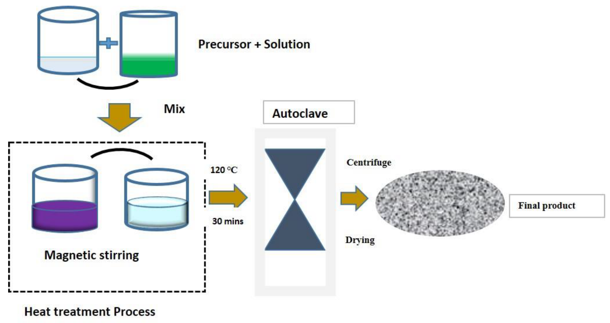
3.2. Hydrothermal Synthesis Technique
This is a process in which a solid material reacts with an aqueous solution at high temperature and pressure in a vessel, resulting in the formation of a nanoparticle. It also belongs to the chemistry-based solution approach, and the name “hydrothermal” was given because water is used as the solvent. This procedure is typically carried out in a steel vessel, also known as an autoclave, where process parameters can be adjusted (adjusting the temperature and pressure of the system). To achieve vapor saturation, temperatures are typically raised above the boiling point of water. Because of its homogeneous precipitation, friendly environment, low cost, pure final product, and ease of scaling up production, hydrothermal synthesis has made significant contributions to modern technologies. The following steps could be used to achieve crystalline growth via a hydrothermal process [
91,
92].
1st Step: Precursors are mixed with the solvent-metal hydroxide and are normally used as the mineralizer in the solution, while metal alkoxides acts as the source of metal ions.
2nd Step: Hydrothermal treatment is carried out in a sealed reactor known as an autoclave, where nourishment is provided alongside H2O, and a variable temperature difference is applied to both the lower and upper sections of the chamber. As a result, ions are transported to a lower temperature region, while seed crystals are transported to a cooler region, where the desired crystals can be collected.
3rd Step: Lastly, the sample should be washed and dried at a varying temperature; this should happen after centrifugal.
The crystal morphologies seen in hydrothermal synthesis are related to growth conditions. This crystal-growth mechanism has already been analyzed and predicted in the study of morphology [
93]. Depending on the reaction composition’s vapour, a high or low-pressure state could be used to ensure morphology control at the nanomaterial level. The concepts of the hydrothermal technique have already been applied in a non-aqueous system using solvothermal techniques. In this technique, inorganic solvents are used in the reaction medium instead of water. Both methods can easily be controlled, and they can both take place in autoclaves or ovens [
94,
95]. The rapid accumulation of nanoparticles in a solvent with a high polarity can lead to the formation of aggregates. As a result, various surfactant must be employed as a capping catalyst to help control the uniformity and morphology of the nanostructured materials [
96,
97]. Hydrothermal techniques have advantages, such as ultrafine gain size, high purity, homogeneous composition, avoiding of the calcination step, and control of particle morphology. The extremely high purity of the powder obtained by this technique is due to the hydrothermal process’s self-crystallization. Impurities are repelled by the crystal growth during self-crystallization. Following that, any remaining impurities in the crystalline solution are filtered out to obtain a powder of high quality and purity. However, unlike the sol-gel technique, which uses expensive alkoxides, the hydrothermal technique uses inexpensive precursors, such as nitrate and polyoxometalates, to synthesize nanomaterials [
98].
The hydrothermal synthesis occurs in an enclosure; thus, some of its chemicals can easily be recycled. This makes the entire process environmentally friendly since little or no emission is allowed during the entire duration of the reaction. In the nineteenth century, the method of hydrothermal synthesis was utilized for the very first time. The method was later used to create ultrafine particles. Recently, the hydrothermal method has been used to produce single oxide powders or composite powders in electrochemistry and photochemistry. Nanopowder with suitable properties can be obtained, as with any other solution-based chemistry technique by varying reaction parameters, such as time, temperature, pH, and precursor of the used material.
Hajalilon and colleagues synthesized CoFe
2O
4 using hydrothermal and sol-gel techniques, resulting in a material with single-phase. The nanoparticle formed by hydrothermal techniques has tiny particle formation with just an average size distribution of 21 nm, as opposed to the 42 nm size formed by sol techniques. Small particles cause high activity because of their capability to occupy microcavities formed by microsize-engineered particles, which large particles cannot access [
46].
Table 4 below illustrates the synthesis steps involved in hydrothermal techniques.
Figure 7 illustrates the hydrothermal-synthesis techniques [
6]. Advantages and disadvantages are listed in
Table 5.
Table 4.
Summary of the various approach involved with the hydrothermal synthesis.
Table 4.
Summary of the various approach involved with the hydrothermal synthesis.
| Nanomaterials | Stabilizing and Reducing Agent | Precursor | Autoclave of Hydrothermal | Condition of Synthesis | Size of Particle | Ref. |
|---|
| TiO2 NPs | 0.5 g BMI. Cl | 0.4 g TiO2 | Filled Teflon tube | Centrifuged and washed with Ethanol for 5 min before drying 80 °C, overnight | 35 nm | [99] |
| ZrO2 NPs | NH4OH | ZrOCl2·8 H2O | Filled Teflon-lined | Centrifuged, washed with acetone, and dried at 90 °C before being calcined at 450 °C for 60 min | 12 nm | [100] |
| NiO NPs | 50 mM urea | Ni(NO3)2·6 H2O | Filled Teflon-lined | Centrifuged, washed, and dried for 5 h at 50 °C, then annealed for 5 h at 40 °C. | (20–50) nm | [91] |
| Fe3O4 NPs | 50 mg polyvinyl | FeCl3·6 H2O | Filled 75 mL Teflon-lined | Filtered, washed, and dried for 3 h at 300 °C | ~65 nm | [101] |
| Ag NPs | Nanocellulose 20 ML | AgNO3 0.1 mL~0.5 ML | Filled 50 mL Teflon- lined | Filled with 50 mL Teflon-lined | 8 nm | [102] |
| Au NPs | “Hydrolyzed spider cobweb 33 ML” | HAuCl4 330 mg | Filled 50 mL Teflon vessel | Centrifuged for 5 min, washed with ethanol, and dried | 40 nm | [103] |
| CuO NPs | NaOH 10 mmol & 1 mL ethylene Diamine | Cu(NO3)2·3 H2O 10 mmol | Filled 60 mL Teflon-lined | Washed with ethanol and dried | ~27.7 nm | [104] |
Table 5.
Advantages and disadvantages of hydrothermal techniques.
Table 5.
Advantages and disadvantages of hydrothermal techniques.
| Advantages | Disadvantages |
|---|
| Control over the size is precise. | Autoclaves are expensive. |
| Low melting point, high vapour pressure, and pyrolysis are all guaranteed. | Crystal growth cannot be observed directly. |
| A high-crystallinity nanocrystal is obtained. | The control is difficult. |


 ,
, 

