Abstract
The fast development of distributed generations enables the microgrid a popular solution for the construction of the modern power grid, where the control behaviors of power electronics converters play a crucial role. Under this scenario, the emulation of microgrid control behaviors is becoming an emerging need for the testing and teaching of the AC microgrid. However, conventional approaches, such as the dynamic simulation test and the Power-Hardware-In-Loop, are still costly or bulky to flexibly recreate the correct characteristics of microgrid including different layers of controls and the interactions among multiple converters. The dynamic simulation test is bulky and costly to emulate various types of control behaviors since all physical components in the test system may need to be adjusted. The high cost of Power-Hardware-In-Loop is mainly caused by the high-performance real-time simulator and power amplifier. In this paper, a novel emulation system is proposed for the testing of the AC microgrid. A low-cost circuit configuration, which includes two face-to-face connected DC–AC converters and some passive loads, is introduced with the possibility of flexibly emulating most of the typical control schemes in an AC microgrid. In addition, a user interface for the real-time operation and measurement of the hardware platform is introduced on a host computer to further facilitate the testing process. Finally, various control schemes in microgrids, including the voltage control, current control, droop control, and secondary control, are validated in the experiment setup based on the proposed emulation approach.
1. Introduction
In recent years, the penetration of distributed generations (DG) in the power grid keeps increasing dramatically. The microgrid has been proposed to integrate a number of DGs and loads on a more autonomous and smaller scale, where power electronic converters are adopted to manage the energy flows among the DGs and the loads [1,2,3,4,5]. The control schemes of converters are critical to the operation of the microgrid [6,7,8,9]; therefore, recreating the control behaviors in the AC microgrid is becoming essential for the testing, as well as teaching activities in this field.
There are various types of control schemes in the converters inside the microgrid. First, proper and basic control is required for the individual converter to regulate the output voltage or current [10,11,12]. Second, the coordination controls, such as power sharing, frequency stabilization, and bus voltage regulation, are achieved by the higher level of control methods considering multiple converters [13,14]. Control systems of both the individual converter and multiple converters should be covered in order to enable the systematic testing and validation for microgrids.
The offline simulation is a common approach for the recreation of microgrid behaviors, and it can be achieved through various simulation software, such as MATLAB, PLECS, PSCAD, etc., and the configurations of microgrid are flexible to be modified and extended [15,16,17,18]. The Controller-Hardware-In-the-Loop (CHIL) is also a common method used for the emulation of microgrids [19]. Compared with the offline simulation test, the actual controller of a converter in microgrids is adopted in CHIL for a more realistic test. However, there are still differences between the actual power microgrid and the microgrid in the simulation. The lack of actual converters makes the offline simulation incapable of testing the actual controllers and loads under the actual power level.
In order to recreate more physical behaviors of microgrid controls, different types of laboratory-scale microgrids have been built, known as dynamic simulation test systems. Down-scale solar arrays, battery banks, converters, transformers, and loads are actually constructed to demonstrate the experiments under both the grid-connected mode and islanding mode of the microgrid [19]. In addition, multiple converters adopting droop controls have been built for the control tests in the microgrids [20,21,22]. However, these dynamic simulation systems have several drawbacks: 1. It is inflexible and difficult to expand/modify the control structure recreated by the down-scaled microgrid system; 2. A high number of actual components is required in the case of the complex configuration of the microgrid. The bulky and costly building of the dynamic simulation system makes it unsuitable for the testing and teaching of the microgrid with variable circuit configurations and control structures.
To achieve more flexible testing, the Power-Hardware-In-Loop (PHIL) approach has been introduced. Only a small number of converters need to be implemented in the PHIL-based experimental system, and the rest of the microgrid features can be recreated in a real-time simulator. In this approach, the configuration and control methods of the microgrid are flexible to be adjusted, and thus, the testing and validation for the complex-structured microgrid can be achieved [23,24,25,26]. However, the high cost of the real-time simulator and power interface in PHIL makes it difficult to increase the number of PHIL systems. Therefore, the extensive application of PHIL to the testing and teaching system is hard to be achieved.
In this paper, a novel emulation approach of microgrids is proposed for the testing and teaching of typical control schemes in AC microgrids, achieving both flexibility and low cost. The low cost of emulation is achieved by only including two converters and passive loads. A voltage-controlled converter and a current-controlled converter are used to emulate the typical voltage behaviors and current behaviors in a microgrid, respectively. In addition, the passive loads are included to emulate the behaviors related to passive loads. A generalized control scheme, including multiple control schemes for the dual converters in a microgrid is proposed to flexibly emulate and modify the typical control behaviors in the AC microgrid. By manipulating the proposed emulation system, the typical control schemes, including the common controls for the individual converter and multiple converters, can be correctly recreated with actual loading in the converters.
2. Typical Control Behaviors to Be Emulated in AC Microgrid
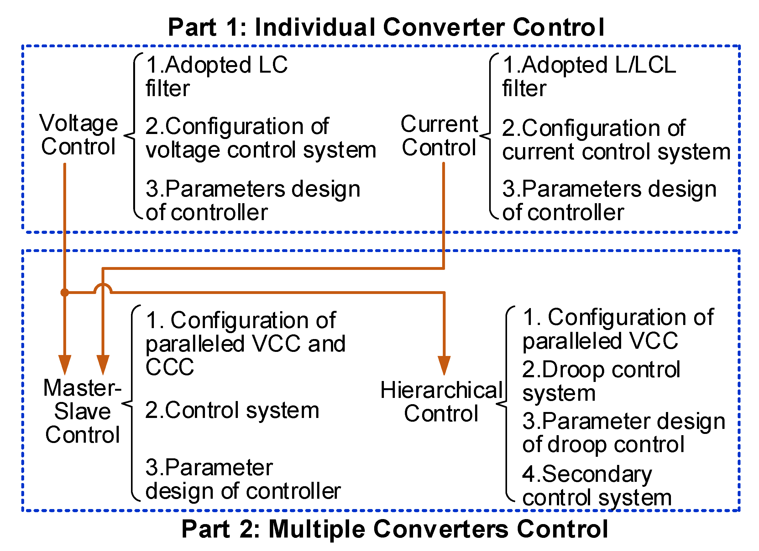
Since various types of control schemes can be implemented in the converters of the microgrid, the testing system should be able to recreate the behaviors related to the control schemes in the microgrid. The typical control schemes in the microgrid can be used for the control of an individual converter or the cooperation of multiple converters. More details of these two types of control schemes are summarized in Figure 1.

Figure 1.
The knowledge coverage of testing and teaching for microgrid controls. VCC: voltage-controlled converter, CCC: current-controlled converter.
The control schemes in Part 1 are used to regulate the behaviors of the individual converter. The first type of control scheme for the individual converter is voltage control. The LC filter is adopted to regulate the output voltage of the converter, and the voltage control system is designed based on the model of the adopted filter. Then, the parameters of the controller need to be calculated. The second type of control scheme in Part 1 is the current control with the adopted L/LCL filter. The current control system and the parameters of the controller can be designed based on the model of the L/LCL filter. In addition, Part 2 is used for the testing of different coordination strategies of multiple converters. First, the master-slave control is used in the paralleled configuration of a single voltage-controlled converter and multiple current-controlled converters. Second, another coordination strategy, namely hierarchical control, is adopted for the multiple voltage-controlled converters. The hierarchical control is a complex control construct of the microgrid. Since the proposed emulation approach is also used for teaching, only the commonly seen control schemes, i.e., the droop control and the secondary control, are focused.
To recreate the behaviors of the above-mentioned control schemes in microgrid, an emulation approach to the microgrid is required. The requirements for the emulation approach are given as follows:
- (1)
- Actual converters of the microgrid should be included to enable the testing of the actual controller and actual loading under actual power level;
- (2)
- The behaviors of different control schemes can be recreated flexibly and modified easily;
- (3)
- The cost needs to be relatively low to achieve the large application for testing and teaching.
3. Configuration of Proposed Testing Method for Microgrid
To meet all requirements for the testing and teaching of microgrid controls, a converter-based emulation approach is proposed in this paper. Only converters and passive load are implemented in the proposed emulation approach achieving the capability of low cost. In addition, the actual converters enable the testing of actual controllers and loads. To emulate the control behaviors shown in Figure 1, different control schemes are implemented in the different converters.
3.1. Circuit Configuration of the Proposed Platform
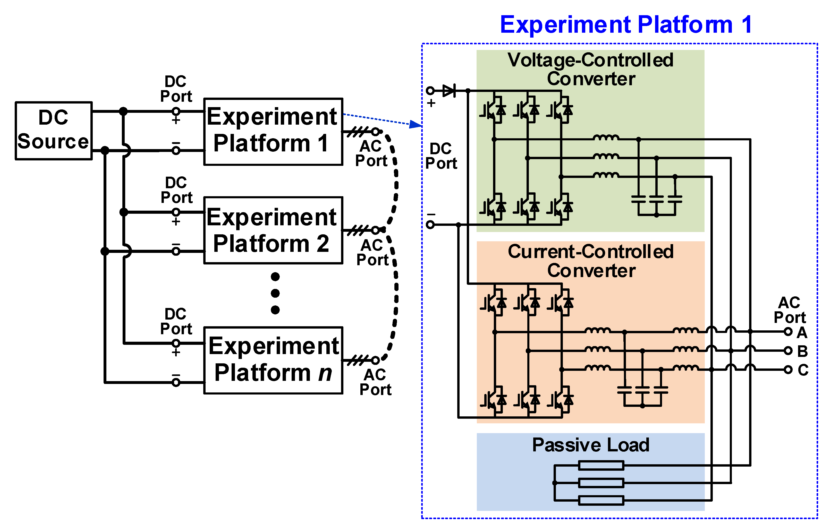
As shown in Figure 1, all the control schemes are achieved based on the voltage control schemes and the current control schemes. Therefore, to recreate all control behaviors in Figure 1, an emulation approach is proposed and the configuration is shown in Figure 2. The proposed emulation approach is composed of several experiment platforms, and the power circuits of all experiment platforms are the same. Each experiment platform is composed of a voltage-controlled converter, a current-controlled converter, and passive loads. Every experiment platform interfaces with other components through the DC port and AC port. The DC port is used for the power supply, and thus, is connected to the DC source. The AC port can be connected to other experiment platforms for the test of microgrids with more complex configurations. The LC filter is adopted to regulate the output voltage of the voltage-controlled converter, and the LCL filter is adopted to regulate the output current of the current-controlled converter. Since both the PCC voltage and PCC current are related to the control behaviors in a microgrid, two converters are face-to-face connected to regulate the AC voltage and AC current simultaneously. The passive load is a common type of load in the microgrid, and thus, the actual passive loads are also used to recreate the control behaviors related to the passive loads. These two converters are powered by a common DC source. Since the power is circulated between two converters, only the power losses of the converters and the passive load need to be supplied by the DC source.
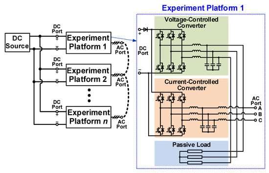
Figure 2.
Power circuit of the proposed emulation approach.
To further increase the number of experimental platforms and save the power supply cost, serval experimental platforms can be powered by a single DC source, as shown in Figure 2. In order to limit the power flow from one experimental platform into another, a diode is placed between the DC power source and each experimental platform. In this case, other microgrids, which may be composed of several converters with different control schemes, can be tested by adopting multiple platforms. Several voltage-controlled converters and current-controlled converters are included in the proposed emulation approach, and different control schemes can be implemented in these converters to emulate different control behaviors in other MV or LV microgrids. The number of experiment platforms and the control schemes can be selected based on the emulated MV or LV microgrid. It is noticed that the line impedance is an important component in the microgrid with a complex configuration, but no actual line impedance is included in the proposed emulation approach. In order to emulate the line impedance, the virtual impedance control schemes can be implemented in the voltage-controlled converters and the current-controlled converters.
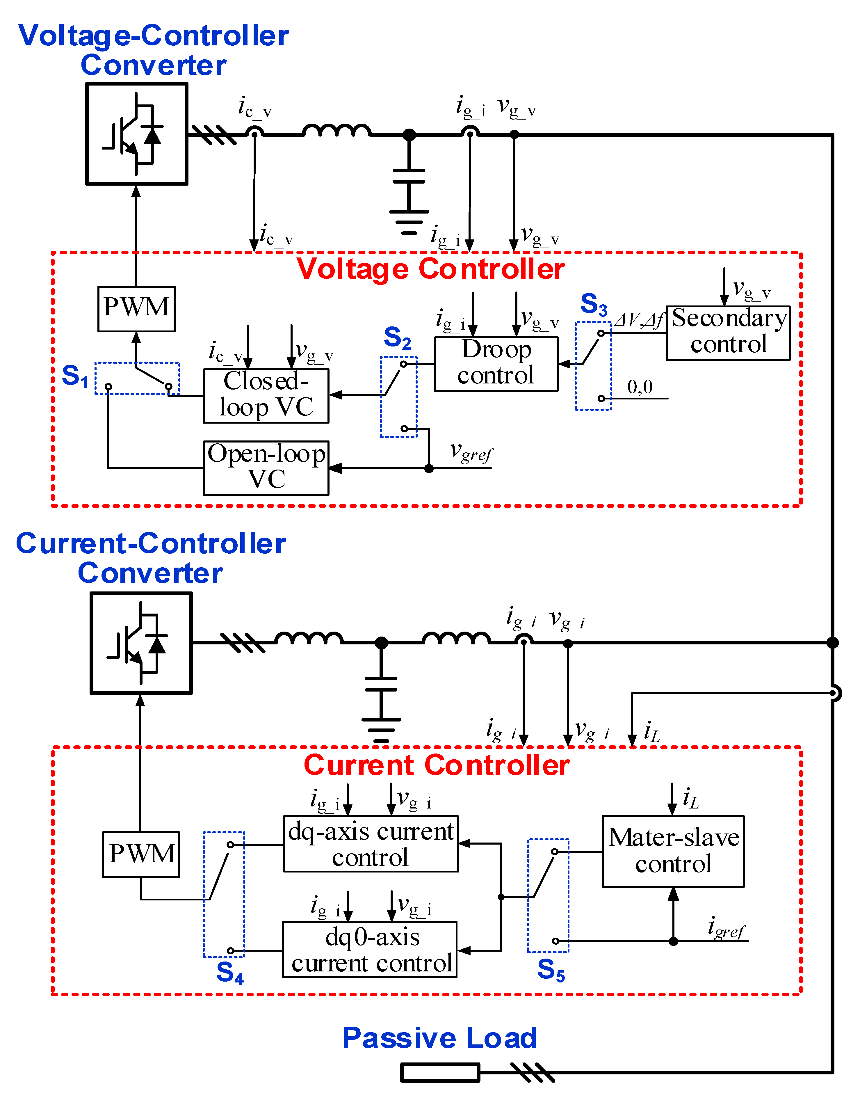
3.2. Control Schemes in the Dual Converters
As shown in Figure 3, two controllers, which include a number of optional control schemes, are adopted for the voltage-controlled converter and the current-controlled converter. On one hand, when the control schemes in the current-controlled converter are under test, the voltage-controlled converter is used to emulate the voltage in the microgrid. On the other hand, the current-controlled converter needs to emulate the active load in order to test the control schemes in the voltage-controlled converter under different loads. Therefore, the different control schemes can be tested by selecting different control systems in different converters. Different types of control schemes can run or stop by selecting the switches, which enables an easy and intuitive comparison among different control schemes. The voltage controller is adopted in the voltage-controlled converter. The switch S1 selects the closed-loop voltage control or open-loop voltage control to regulate the output voltage, and the comparison between closed-loop voltage control and open-loop voltage control can be achieved. The voltage reference of the closed-loop voltage control schemes can be a constant reference or a variable reference generated by the droop control based on the switch S2. The effect of the droop control on the amplitude and frequency of the voltage can be observed by selecting S2. Since the voltage reference generated by the droop control may vary from the given voltage in the industry standard, the secondary control system can be adopted to eliminate these deviations. The secondary control system can be enabled through switch S3, and generates the compensation of voltage amplitude and frequency for the droop control. Therefore, the principle of the secondary control system can be validated by selecting the S3.
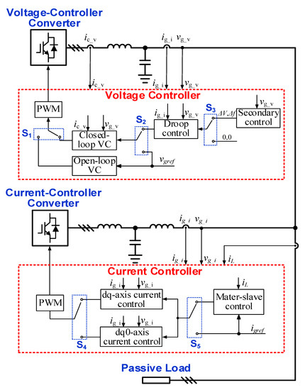
Figure 3.
Control system of the proposed emulation approach. VCC: voltage-controlled converter, CCC: current-controlled converter, VC: voltage control.
As shown in Figure 3, the current controller is adopted in the current-controlled converter. Three types of current control schemes are needed for testing and teaching, namely, the dq-axis current control, the dq0-axis current control, and the master-slave control. Either the dq-axis current control or the dq0-axis current control should be adopted in the current-controlled converter to regulate the output current, and the selection is based on the switch S4. Therefore, adjusting the S4 enables the validation of the 0-axis current controller. The references of the current control can be either a constant reference or the reference generated from the master-slave control based on the switch S5. The master-slave control is used to ensure the constant output power of the voltage-controlled converter by adjusting the references of the current-controlled converter. The power-sharing between different control schemes can be compared by changing the S5.
Based on the adopted control schemes in the two converters, the control behaviors included in Figure 1 can be covered by selecting different control schemes. First, the control behaviors in Part 1 can be recreated by selecting the closed-loop voltage control with a constant reference or the current control with a constant reference in the two converters. Second, the cooperation control behaviors in Part 2 can be emulated by adopting corresponding control schemes in the two converters. The master-slave control behaviors can be recreated by adopting only the closed-loop voltage control in the voltage-controlled converter and adopting the master-slave control in the current-controlled converter. The power-sharing of two converters under different passive loads is used to validate the principle of the master-slave control. The hierarchical control behaviors can be emulated by selecting only the current control in the current-controlled converter and selecting the droop control and secondary control in the voltage-controlled converter. The current-controlled converter can be considered a constant power load in this case. Therefore, the control behaviors of the hierarchical control under different power loads can be validated and compared easily.
Furthermore, the more complex control behaviors in the microgrids can be recreated flexibly by the proposed emulation approach. The low-voltage ride-through behaviors can be recreated by adopting the voltage sag emulation in the voltage-controlled converters. The economic dispatch among multiple droop-controlled converters can be achieved by the parallel-connected experimental platform with multiple droop-controlled converters.
3.3. User Interface of the Host Computer
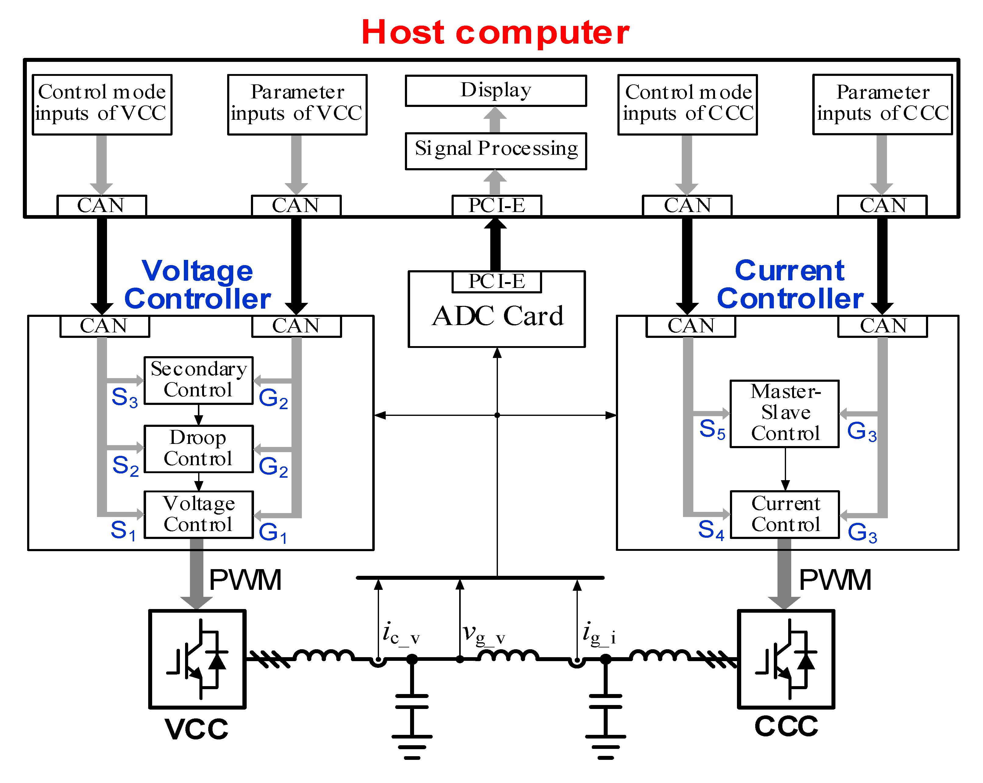
The voltage-controlled converter and current-controlled converter are controlled by two separate digital controllers in the experimental platform. A user interface is designed in the host computer to select the control schemes and change the parameters by communicating with the digital controllers. In addition, various types of voltage and current need to be measured for display. Thereby, the user interface is also required to display the measured voltage and current for easy operation.
The configuration of the user interface is shown in Figure 4, the control schemes and parameters of the control schemes can be flexibly adjusted. The user interface communicates with two controllers and receives the signals in measurement. Two types of signals, i.e., the mode of switches and parameter groups, are transmitted from the host computer to the two controllers. The switches S1, S2, and S3 are transmitted into the voltage controller of the voltage-controlled converter to select the control schemes. All parameters of the open-loop voltage control and the closed-loop voltage control are included in the parameter group G1. The parameter group G2 comprises all parameters of the droop control and secondary control. The selection of S4 and S5 is sent from the user interface into the current controller of the current-controlled converter. All parameters of control schemes in the current-controlled converter are included in the parameter group G3. All types of sampled voltage and current can be displayed in the user interface. In addition, signal processing is adopted for the additional mathematical calculation of sampled voltage and current, and the results can be displayed in the interface as well.
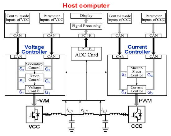
Figure 4.
Configuration of the user interface in the host computer. VCC: voltage-controlled converter, CCC: current-controlled converter.
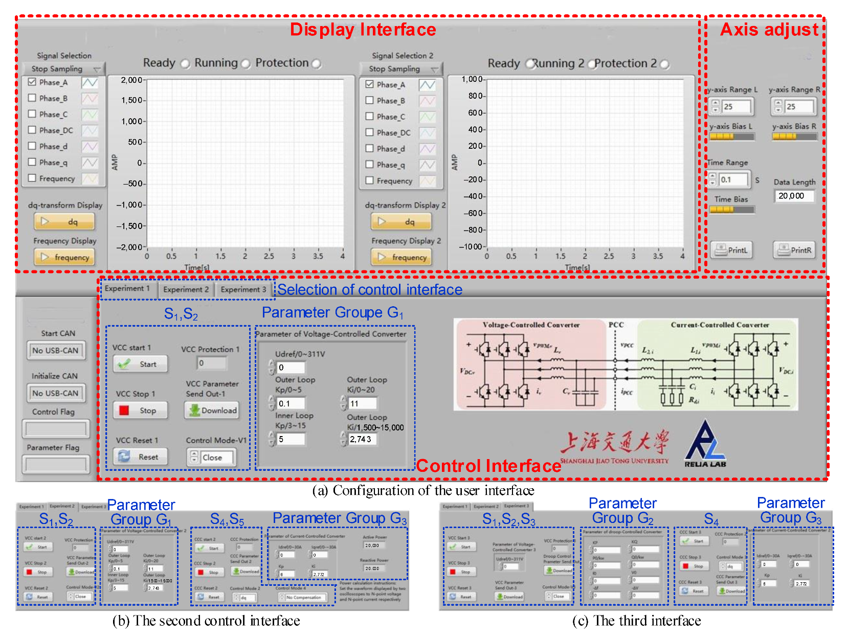
The actual user interface is developed based on LabVIEW, and is shown in Figure 5. Two types of processes can be tested in the proposed platform by using the user interface. First, the impact of different control schemes on the voltage and current can be tested. The user interface is shown below. Different control schemes can be switched by selecting switches S1–S5. Different types of voltage and current can be displayed in the display interface. Second, the impact of different parameters on the voltage and current can be tested. Different parameters of control schemes can be set by inputting the number in parameter groups G1–G3.
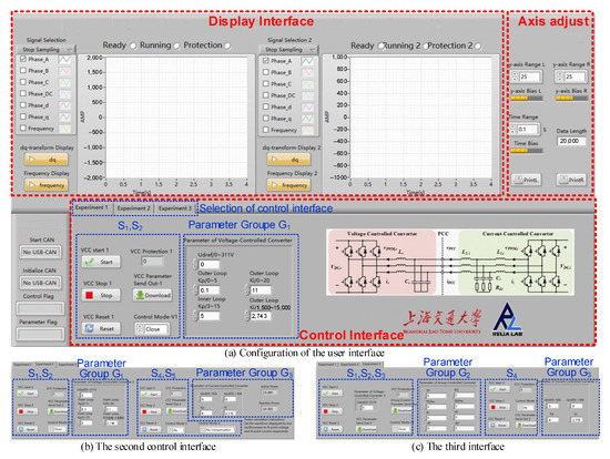
Figure 5.
The actual user interface of the proposed emulation approach.
4. Experimental Validation
To validate the proposed emulation approach, different control behaviors should be recreated. Therefore, different types of control schemes shown in Figure 1 are implemented in the two converters.
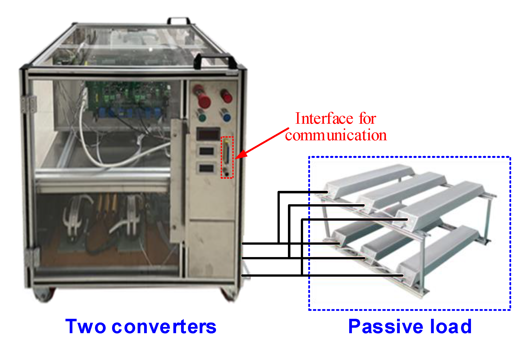
The proposed experimental platform is shown in Figure 6; all components of two converters are placed in an enclosed case. The communication interfaces are placed in front of the enclosed case to communicate with the host computer for real-time operation. The electric interfaces are placed in the back of the enclosed case to connect with the DC power source and the passive load. To ensure stable operation, the parameters of the proposed experimental platform are designed due to [26,27], and are shown in Table 1.

Figure 6.
Experimental platform of proposed emulation approach.

Table 1.
Parameters of the experimental platform.
4.1. Voltage Control
The parameters of voltage control are critical elements affecting the stability of the voltage-controlled converter, and such an impact can be validated in the proposed emulation approach. Due to the face-to-face configuration of two converters, the current-controlled converter may affect the stability of this system [26]. Therefore, the current-controlled converter is stopped in the validation of voltage control. The parameters of droop control also elements that may distort the stability behaviors [28]. The droop control is inactive to focus on the impact caused by the parameters of voltage control.
The typical dual-loop voltage control scheme is adopted in the voltage-controlled converter, and the PI controllers are used as the voltage controller and current controller in the typical dual-loop voltage control scheme. The stability of the voltage-controlled converter is affected by the parameters of the voltage controller, and the parameters are shown in Table 2.
Table 2.
Parameters of the dual-loop voltage control scheme.
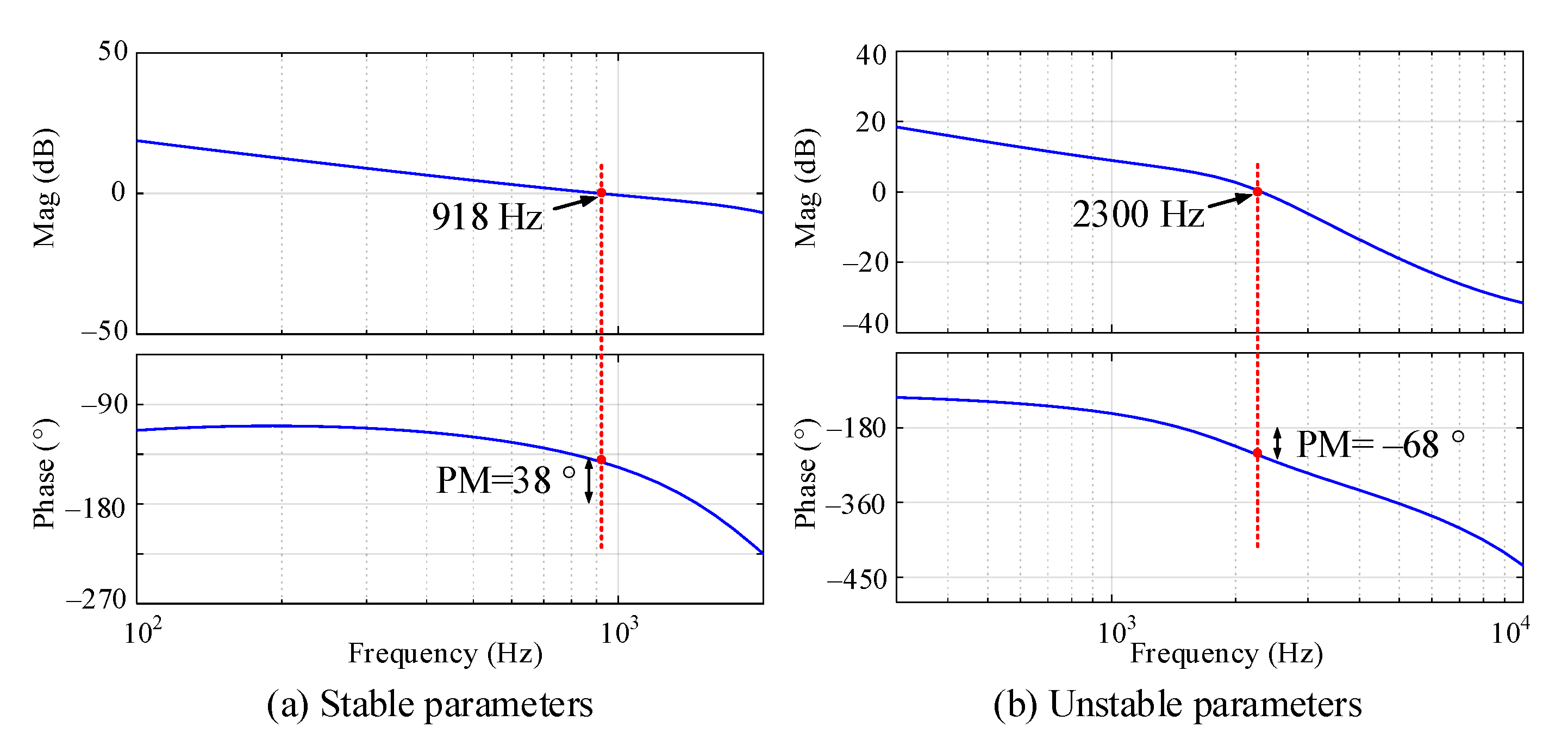
It is known that increasing the proportion coefficient of the voltage controller will increase the bandwidth of the voltage control but decrease the stability margin. The bode diagram is shown in Figure 7. When the first group of parameters is used, the crossover frequency is 918 Hz and the phase margin is 38 degrees. Therefore, the voltage-controlled converter is stable by adopting the first group of parameters. When the second group of parameters is used, the crossover frequency is 2300 Hz and the phase margin is −68 degrees. Therefore, the voltage-controlled converter is unstable by adopting the second group of parameters.
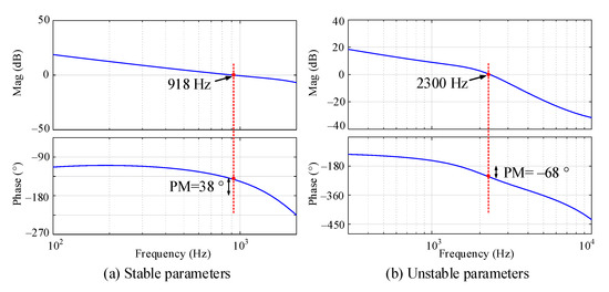
Figure 7.
The bode diagram of the open-loop transfer function of the voltage control system.
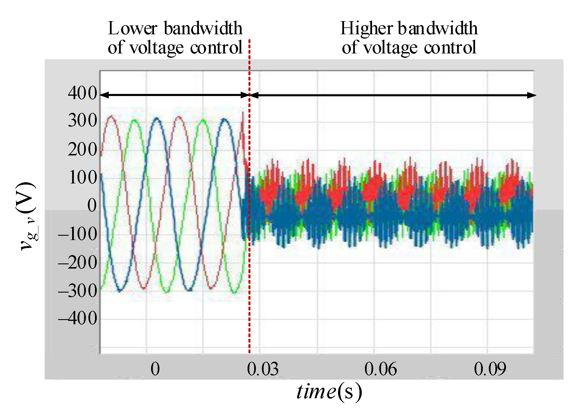
The PCC voltage in the proposed experimental platform is shown in Figure 8. It is shown that the system is stable at first. Then, the bandwidth of voltage control has increased by increasing the parameters of the voltage controller. It is shown that the system becomes unstable when the bandwidth of voltage control increases.
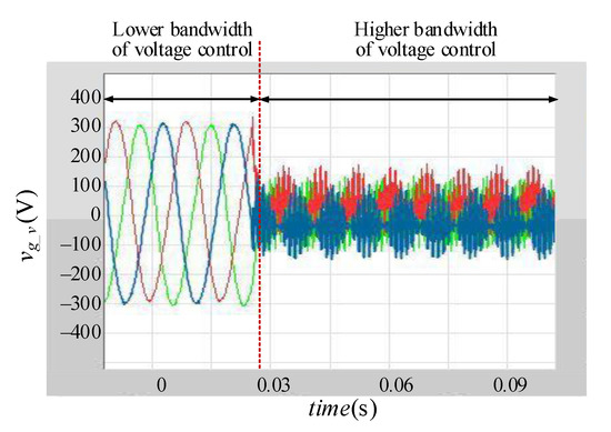
Figure 8.
The closed-loop voltage control under the unstable region when vdref is 311 V.
4.2. Current Control
The current control is another control scheme of an individual converter that can be testing and teaching in the proposed experimental platform. Due to the common DC power supply of voltage-controlled converter and the current-controlled converter, there may be 0-axis current in the output current of the current-controlled converter. Therefore, the 0-axis current controller has a significant impact on the output current of the current-controlled converter, and such an impact can be validated in the proposed experimental platform. In this testing system, the PCC voltage needs to be regulated by the voltage-controlled converter.
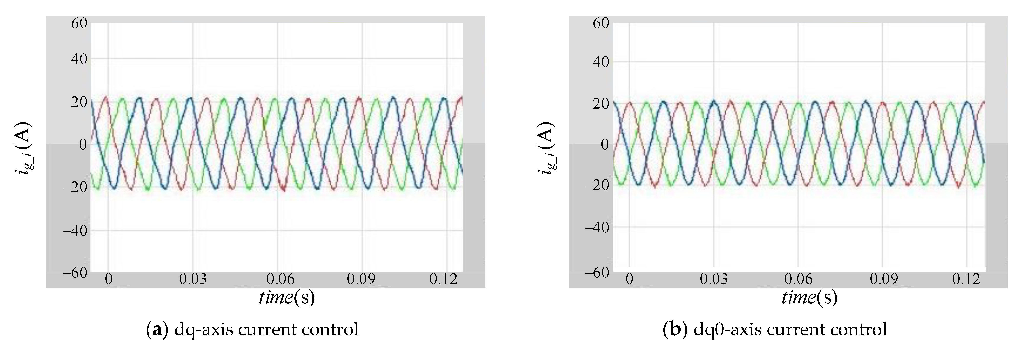
First, the 0-axis current control is inactivated in the current-controlled converter, and the output current of the current-controlled converter is shown in Figure 9a, where the 0-axis current is obvious. Second, the dq0-axis current control is adopted for the control scheme in the current-controlled converter, and the output current of the current-controlled converter is shown in Figure 9b. It is shown that there is little 0- axis current due to the 0-axis current controller.
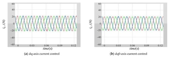
Figure 9.
The output current of the current-controlled converter under different current control schemes when idref is 20 A. (a) dq-axis current control; (b) dq0-axis current control.
4.3. Master-Slave Control
The master-slave control can be used for teaching and testing in the proposed experimental platform by the operation of the current-controlled converter and the passive load. The closed-loop voltage control scheme with constant reference is implemented in the voltage-controlled converter to regulate the PCC voltage. The master-slave control is implemented in the current-controlled converter to keep the output power of the voltage-controlled converter constant no matter what the passive load is.
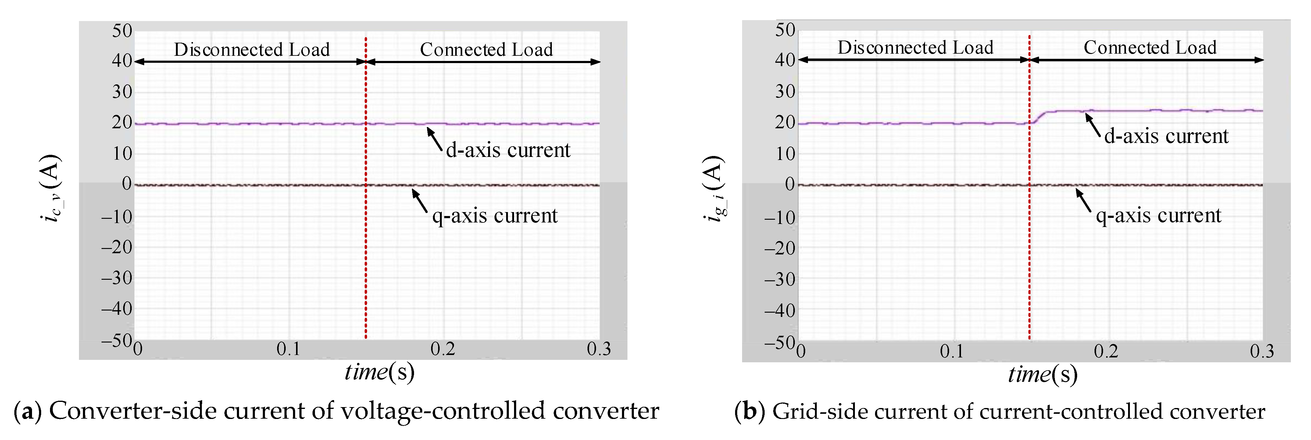
The resistive load is disconnected to converters at first and then connected to the converters. The output current of the voltage-controlled converter and the current-controlled converter are shown in Figure 10a,b, respectively. It is shown that the d-axis current of the current-controlled converter increases when the passive load is connected. On the contrary, the output current of the voltage-controlled converter keeps constant when the passive load is connected and disconnected. Therefore, the output power of the voltage-controlled converter keeps constant due to the master-slave control.
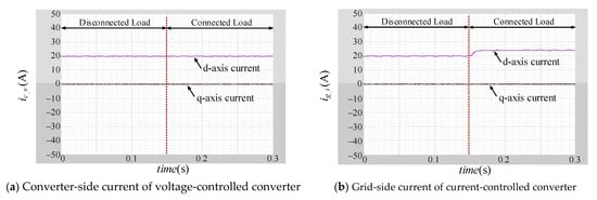
Figure 10.
The output current of two converters under master-slave control (load is 150 Ω). (a) Converter-side current of voltage-controlled converter; (b) Grid-side current of current-controlled converter.
4.4. Hierarchical Control
The testing and teaching of hierarchical control can be achieved by adjusting the control schemes in the voltage-controlled converter. The current-controlled converter is considered a constant power load in this type of testing and teaching. The active power can be regulated by adjusting the d-axis current reference and the reactive power can be regulated by adjusting the q-axis current reference.
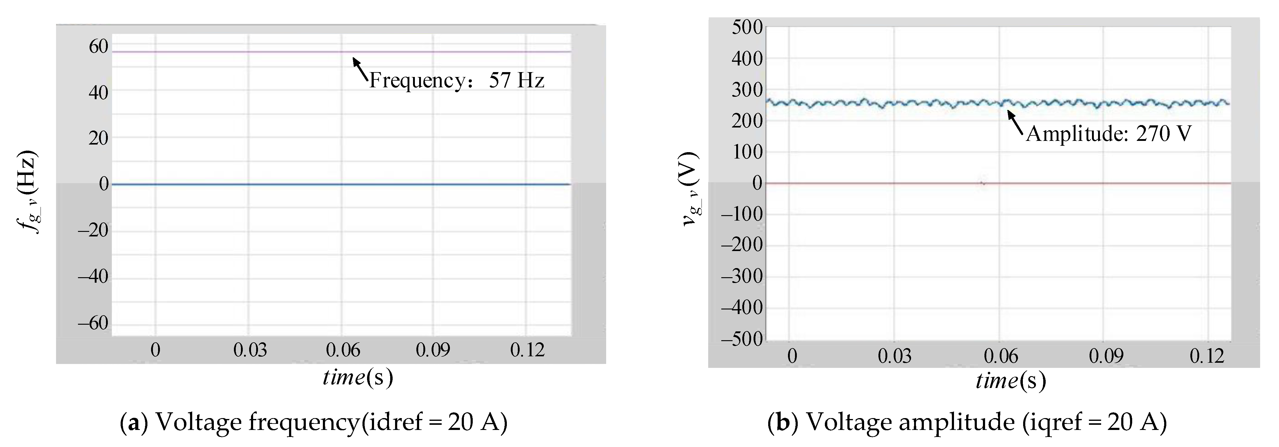
First, only the droop control is implemented in the voltage-controlled converter. The d-axis current reference of the current-controlled converter is set as 20 A to validate the P-f behaviors. The frequency of the output voltage is shown in Figure 11a. It is shown that the decreasing active power results in the increased frequency of voltage. The q-axis current reference of the current-controlled converter is set as 20 A to validate the Q-V behaviors. The amplitude of output voltage is shown in Figure 11b. The increasing reactive power results in the decreasing amplitude of the voltage.
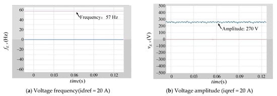
Figure 11.
The frequency and amplitude of output voltage under droop control (f0 = 50 Hz, V0 = 300 V). (a) Voltage frequency (idref = 20 A); (b) Voltage amplitude (iqref = 20 A).
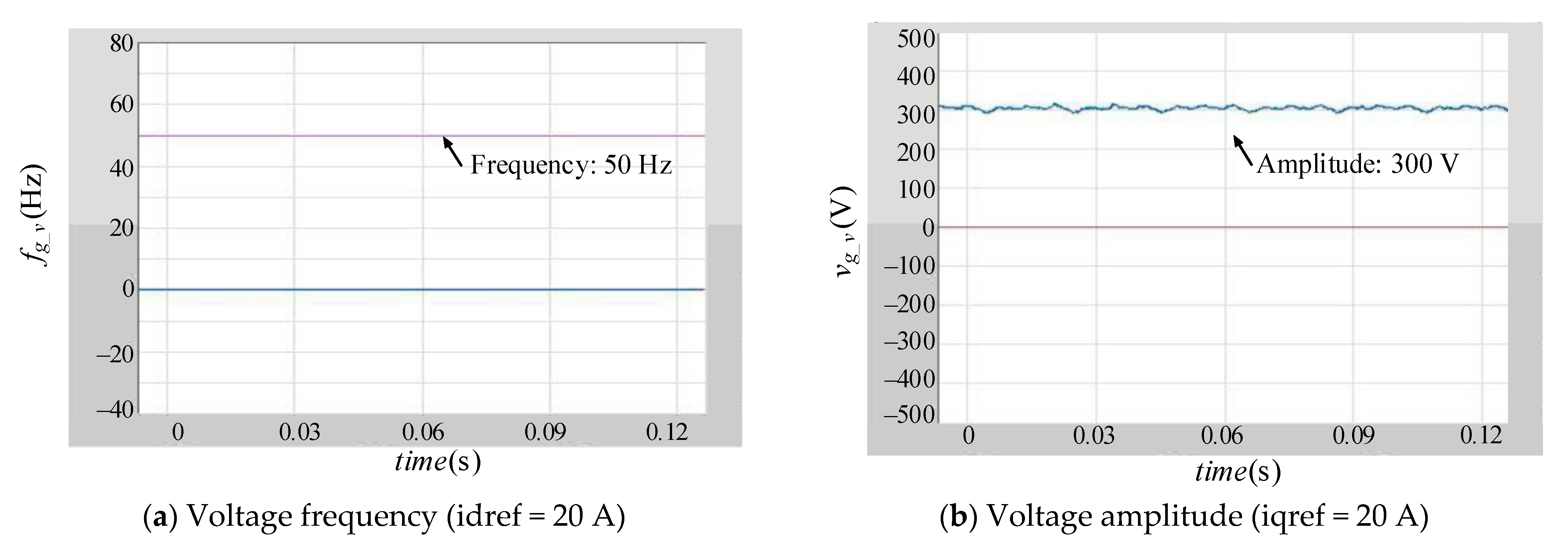
Second, the secondary control is implemented in the voltage-controlled converter to eliminate the error of frequency and amplitude of voltage caused by the droop control. The frequency of voltage under the secondary control is shown in Figure 12a and is equal to the given frequency due to the compensation generated by the secondary control. The amplitude of voltage under the secondary control is shown in Figure 12b and is equal to the given amplitude due to the compensation generated by the secondary control.
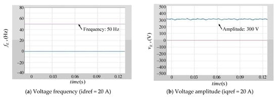
Figure 12.
The frequency and amplitude of output voltage under secondary control (f0 = 50 Hz, V0 = 300 V). (a) Voltage frequency (idref = 20 A); (b) Voltage amplitude (iqref = 20 A).
5. Discussions
The above findings demonstrate that the proposed emulation approach can achieve flexible and low-cost testing compared with the conventional emulation approaches. The comparison in three aspects, i.e., containing actual converters, the flexibility of testing different control schemes, and the cost, should be discussed. First, whether the emulation approaches contain actual converters needs to be discussed. The actual converters are implemented in the dynamic simulation test, PHIL, and the proposed emulation approach, but are not included in the offline simulation and CHIL. The actual converters enable the test related to the actual load and actual passive loads. Second, testing different control schemes can be achieved by different methods in different emulation approaches. In the offline simulation, different control schemes can be tested by adjusting the simulation model, and thus, it is the most flexible testing of different control schemes in microgrids. Compared with the offline simulation, the additional actual controller is required as the device under test. Therefore, both the model in simulation and the actual controller are required to be adjusted in the CHIL. Due to the physical components in the dynamic simulation test, different control schemes testing may require all the physical components to be reset. It makes the dynamic simulation test the hardest approach to testing different control schemes. The PHIL and proposed approach can test different control schemes by modifying the model in the real-time simulator of PHIL, or the user interface of the proposed approach. Thereby, the flexibility of testing by PHIL and the proposed approach is higher than the dynamic simulation by lower than the offline simulation and CHIL. Finally, the cost of all approaches needs to be taken into account. The offline simulation Is the cheapest approach due it only requiring computers. The CHIL is a little expensive due to the additional actual controllers. The dynamic simulation test is high-cost since all physical components are needed, and the cost increases with the configuration of the microgrid. The PHIL is also a high-cost approach. In order to achieve the real-time simulation of the microgrid, the high-performance real-time simulator, which is very expensive, is needed in PHIL. In addition, high-performance power amplifiers are used to accurately and rapidly amplify the reference generated by PHIL. The proposed approach is composed of converters and passive loads. On one hand, due to the limited number of converters, the proposed approach is more low-cost than the dynamic simulation test. On the other hand, the high-price components in PHIL, such as real-time simulators and power amplifiers, are not needed in the proposed approach. In this case, the cost of the proposed approach is lower than that of PHIL and the dynamic simulation test, but higher than that of CHIL and offline simulation. The summary is shown in Table 3.
Table 3.
Comparisons of different concepts for testing microgrid controls.
The proposed emulation approach is also applicable to teaching. In order to improve the teaching quality and effect, this approach has undergone several rounds of updates based on the feedback from the students. During the four-year teaching process, most students managed to grasp a systematic knowledge framework of the microgrid. According to the comments from students, most of the students were satisfied with the teaching method and the teacher-student interaction during the teaching process.
However, there are still some limits to the proposed approach. First, only the fundamental-frequency characteristics are focused on in the proposed approach due to the limited bandwidth of the two converters in the experiment platform. Second, the limited number of converters restricts the flexible expansion of the configuration of the microgrid. Third, communication is an important component in microgrids and has significant impacts on control behaviors, but it is not focused on in this paper.
6. Conclusions
An emulation approach is proposed in this paper for the flexible and low-cost testing and teaching of AC microgrid control behaviors. The low-cost power circuit of the proposed experiment platform only includes two converters and passive loads. The actual converters enable the testing of actual controllers and actual loads. A voltage-controlled converter and a current-controlled converter are adopted to emulate the voltage behaviors and current behaviors, respectively. Therefore, the emulation of a complex-configuration microgrid can be achieved by the parallel connection of multiple experiment platforms and different control schemes in the converters of different platforms. In this case, the typical control schemes in a microgrid, including voltage control, current control, master-slave control, and hierarchical control, are flexibly validated in a proposed platform. In addition, a user interface is used for easy operation.
Based on the proposed power circuit of the parallel-connected experiment platforms, the proposed emulation approach can be used to test the control system in a complex-configuration microgrid. However, the control systems in multiple converters need further research to recreate the more complex control behaviors.
Author Contributions
Conceptualization, K.M.; methodology, K.M.; software, J.W., K.M.; validation, J.W.; formal analysis, J.W.; resources, K.M.; data curation, J.W.; writing—original draft preparation, J.W.; writing—review and editing, K.M., T.L.; visualization, J.W.; supervision, K.M.; project administration, K.M.; funding acquisition, T.L. All authors have read and agreed to the published version of the manuscript.
Funding
This research was funded by International Chinese Education Research Funding in 2022, funded by Centre for Language Education and Cooperation, Ministry of Education, China, grant number 22YH94C.
Institutional Review Board Statement
Not applicable.
Informed Consent Statement
Not applicable.
Data Availability Statement
Data sharing is not applicable to this article.
Conflicts of Interest
The authors declare no conflict of interest. The funders had no role in the design of the study, in the collection, analyses, or interpretation of data, in the writing of the manuscript, or in the decision to publish the results.
References
- Shan, Y.; Hu, J.; Chan, K.W.; Fu, Q.; Guerrero, J.M. Model Predictive Control of Bidirectional DC–DC Converters and AC/DC Interlinking Converters—A New Control Method for PV-Wind-Battery Microgrids. IEEE Trans. Sustain. Energy 2018, 10, 1823–1833. [Google Scholar] [CrossRef]
- Ma, K.; Xia, S.; Qi, Y.; Cai, X.; Song, Y.; Blaabjerg, F. Power-Electronics-Based Mission Profile Emulation and Test for Electric Machine Drive System—Concepts, Features, and Challenges. IEEE Trans. Power Electron. 2022, 37, 8526–8542. [Google Scholar] [CrossRef]
- Bhuvaneswari, G.; Singh, B. A Reliable Microgrid Comprising Solar PV-WEGS and Battery with Seamless Power Transfer Capability. IEEE Trans. Ind. Electron. 2020, 68, 9665–9674. [Google Scholar] [CrossRef]
- Ma, K.; Wang, J.; Cai, X.; Blaabjerg, F. AC Grid Emulations for Advanced Testing of Grid-Connected Converters—An Overview. IEEE Trans. Power Electron. 2020, 36, 1626–1645. [Google Scholar] [CrossRef]
- Wang, J.; Ma, K.O.G.; Tang, W.; Cai, X.; Zheng, L.; Li, X.; Wang, A. Dual-Frequency Bands Grid Impedance Emulator for Stability Test of Grid-Connected Converters. IEEE Trans. Power Electron. 2022, 37, 13070–13080. [Google Scholar] [CrossRef]
- Guerrero, J.M.; Chandorkar, M.; Lee, T.-L.; Loh, P.C. Advanced Control Architectures for Intelligent Microgrids—Part I: Decentralized and Hierarchical Control. IEEE Trans. Ind. Electron. 2013, 60, 1254–1262. [Google Scholar] [CrossRef]
- Guerrero, J.M.; Vasquez, J.C.; Matas, J.; de Vicuna, L.G.; Castilla, M. Hierarchical Control of Droop-Controlled AC and DC Microgrids—A General Approach Toward Standardization. IEEE Trans. Ind. Electron. 2011, 58, 158–172. [Google Scholar] [CrossRef]
- Awal, M.A.; Yu, H.; Tu, H.; Lukic, S.M.; Husain, I. Hierarchical Control for Virtual Oscillator Based Grid-Connected and Islanded Microgrids. IEEE Trans. Power Electron. 2019, 35, 988–1001. [Google Scholar] [CrossRef]
- Qi, Y.; Ma, K.; Tang, W. Full-Bandwidth Mission Profile Emulation of the Electric Machine System with Voltage Reference Signal Transmission. IEEE Trans. Power Electron. 2021, 37, 3473–3483. [Google Scholar] [CrossRef]
- Rocabert, J.; Luna, A.; Blaabjerg, F.; Rodríguez, P. Control of Power Converters in AC Microgrids. IEEE Trans. Power Electron. 2012, 27, 4734–4749. [Google Scholar] [CrossRef]
- Lascu, C. Sliding-Mode Direct-Voltage Control of Voltage-Source Converters with LC Filters for Pulsed Power Loads. IEEE Trans. Ind. Electron. 2020, 68, 11642–11650. [Google Scholar] [CrossRef]
- Brandao, D.I.; dos Santos, R.P.; Silva, W.W.A.; Oliveira, T.R.; Donoso-Garcia, P.F. Model-Free Energy Manage-ment System for Hybrid Alternating Current/Direct Current Microgrids. IEEE Trans. Ind. Electron. 2021, 68, 3982–3991. [Google Scholar] [CrossRef]
- Heydari, R.; Dragicevic, T.; Blaabjerg, F. High-Bandwidth Secondary Voltage and Frequency Control of VSC-Based AC Microgrid. IEEE Trans. Power Electron. 2019, 34, 11320–11331. [Google Scholar] [CrossRef]
- Espina, E.; Cardenas-Dobson, R.; Espinoza-B, M.; Burgos-Mellado, C.; Saez, D. Cooperative Regulation of Imbalances in Three-Phase Four-Wire Microgrids Using Single-Phase Droop Control and Secondary Control Algorithms. IEEE Trans. Power Electron. 2019, 35, 1978–1992. [Google Scholar] [CrossRef]
- Xu, R.; Zhang, C.; Xu, Y.; Dong, Z.Y.; Zhang, R. Multi-Objective Hierarchically-Coordinated Volt/Var Control for Active Distribution Networks With Droop-Controlled PV Inverters. IEEE Trans. Smart Grid 2021, 13, 998–1011. [Google Scholar] [CrossRef]
- Bloemink, J.; Manson, K.; Palizban, H.; Islam, N. BCIT Integrated Grid Laboratory Planning Framework. In Proceedings of the 2018 IEEE PES/IAS PowerAfrica, Cape Town, South Africa, 28–29 June 2018; pp. 1–6. [Google Scholar] [CrossRef]
- Birchfield, A.B.; Overbye, T.J.; Davis, K.R. Educational Applications of Large Synthetic Power Grids. IEEE Trans. Power Syst. 2018, 34, 765–772. [Google Scholar] [CrossRef]
- Zimmerman, R.D.; Murillo-Sanchez, C.E.; Thomas, R.J. MATPOWER: Steady-State Operations, Planning, and Analysis Tools for Power Systems Research and Education. IEEE Trans. Power Syst. 2010, 26, 12–19. [Google Scholar] [CrossRef]
- Coleman, N.S.; Ogawa, K.L.; Hill, J.; Miu, K.N. Reconfigurable Distribution Automation and Control Laboratory: Solar Microgrid Experiments. IEEE Trans. Power Syst. 2018, 33, 6379–6386. [Google Scholar] [CrossRef]
- Peng, J.C.H.; Raman, G.; Soon, J.L.; Hatziargyriou, N.D. Droop-Controlled Inverters as Educational Control Design Project. IEEE Trans. Power Syst. 2022, 37, 1623–1633. [Google Scholar] [CrossRef]
- Fan, B.; Li, Q.; Wang, W.; Yao, G.; Ma, H.; Zeng, X.; Guerrero, J.M. A Novel Droop Control Strategy of Reactive Power Sharing Based on Adaptive Virtual Impedance in Mi-crogrids. IEEE Trans. Ind. Electron. 2022, 69, 11335–11347. [Google Scholar] [CrossRef]
- An, R.; Liu, Z.; Liu, J.; Liu, B. A Comprehensive Solution to Decentralized Coordinative Control of Distributed Generations in Islanded Microgrid Based on Dual-Frequency-Droop. IEEE Trans. Power Electron. 2021, 37, 3583–3598. [Google Scholar] [CrossRef]
- Martin, D.; Dickey, C. Hardware-in-the-loop for power and telecommunications co-simulation with applications. In Proceedings of the ISGT 2014, Washington, DC, USA, 19–22 February 2014; pp. 1–5. [Google Scholar]
- Hoke, A.F.; Nelson, A.; Chakraborty, S.; Bell, F.; McCarty, M. An Islanding Detection Test Platform for Multi-Inverter Islands Using Power HIL. IEEE Trans. Ind. Electron. 2018, 65, 7944–7953. [Google Scholar] [CrossRef]
- Kotsampopoulos, P.C.; Kleftakis, V.A.; Hatziargyriou, N.D. Laboratory Education of Modern Power Systems Using PHIL Simulation. IEEE Trans. Power Syst. 2016, 32, 3992–4001. [Google Scholar] [CrossRef]
- Lauss, G.; Strunz, K. Accurate and Stable Hardware-in-the-Loop (HIL) Real-Time Simulation of Integrated Power Electronics and Power Systems. IEEE Trans. Power Electron. 2020, 36, 10920–10932. [Google Scholar] [CrossRef]
- Ma, K.; Tang, W.; Cheng, R.; Song, Y. Modeling of Interconnected Voltage and Current Controlled Converters With Coupled LC–LCL Filters. IEEE Trans. Power Electron. 2021, 36, 3995–4005. [Google Scholar] [CrossRef]
- Tang, W.; Ma, K.; Song, Y. Critical Damping Ratio to Ensure Design Efficiency and Stability of LCL Filters. IEEE Trans. Power Electron. 2020, 36, 315–325. [Google Scholar] [CrossRef]
Disclaimer/Publisher’s Note: The statements, opinions and data contained in all publications are solely those of the individual author(s) and contributor(s) and not of MDPI and/or the editor(s). MDPI and/or the editor(s) disclaim responsibility for any injury to people or property resulting from any ideas, methods, instructions or products referred to in the content. |
© 2023 by the authors. Licensee MDPI, Basel, Switzerland. This article is an open access article distributed under the terms and conditions of the Creative Commons Attribution (CC BY) license (https://creativecommons.org/licenses/by/4.0/).