Abstract
This article presents an analysis of the driveline operation of a high-mobility Jelcz 442.32 wheeled vehicle, which uses rigid drive axles connected to drive shafts with two universal joints (another name for the Cardan joints) due to the occurrence of kinematic incompatibility. The conditions for the correct connection of the drive shafts with two universal joints (Cardan joints) were presented, and the kinematic ratio of the complete drive shaft was defined. In the analysis of kinematic incompatibility regarding (but not limited to) the method of loading the vehicle, selected characteristic conditions of vehicle movement and the initial values of the angular setting of the rigid driving axles in relation to the vehicle body were presented. It has been shown that, in the analyzed vehicle, the kinematic incompatibility in the driveline is constantly present, and the value of this incompatibility, represented by the temporary ratio of drive shafts, depends on, among other things, the ways of loading the vehicle, the existing conditions of vehicle movement, and the type of ground. Moreover, the value of the arising kinematic incompatibility was noticed to be highly influenced by the correct manufacturing and assembly of the vehicle springs.
1. Introduction
High mobility wheeled vehicles, with both medium and increased load capacity [1], classified according to the type of approval of N3G group vehicles [2], have a complex driveline, supplying power and torque to all driving wheels [3], which ensures sufficiently high mobility and pulling force [4]. While driving, the suspension system is subjected to heavy loads resulting from traffic conditions [5], which include: road profile, driving speed [6], the degree of capacity utilization, and the maneuvers performed among other factors. Relative displacements of the chassis and driveline elements arising while driving may lead to such temporary mutual positions in which optimal cooperation conditions are not ensured and, as a consequence, additional undesirable loads may be generated [7,8]. Frequent and long-lasting additional loads lead to accelerated wear of the elements of cooperating subassemblies and reduce the driving comfort of the transported people [9], and can also be partially transferred to the transported load and equipment [10]. Therefore, to evaluate this type of vehicle driveline and suspension cooperation, relevant analysis is necessary, the performance of which should allow for the identification of the conditions for the cooperation of the driveline components and reduce the kinematic incompatibility in the driveline system [11], which is understood as the difference in angular velocity of the driving and driven shaft elements.
2. The Characteristics of the Research Object
High-mobility wheeled vehicles with different payloads remain a universal means of transporting people and goods in the current vehicle structure of the Polish Armed Forces. As part of the modernization of the Armed Forces, the existing basic high-mobility wheeled vehicle with a 6 × 6 chassis, the Star 266, is successively being replaced by a new truck with a 4 × 4 driveline system, the Jelcz 442.32. Initial tactical and technical assumptions for this new vehicle were defined in 2011. They indicated, among other things, that it should be a vehicle with a minimum load capacity of 6000 kg (with a 2-person cabin) capable of carrying up to 24 soldiers, with a GVM (Gross Vehicle Mass) not exceeding 16,000 kg, approved for traffic on public roads, susceptible to configuration changes, and able to move at a speed of up to 80 km/h in accordance with the regulations enforced [12]. Due to the anticipated conditions of use, the vehicle should be able to: negotiate slopes of 30° (longitudinal) and 20° (transverse), drive over ditches a minimum of 0.6 m wide, vertical walls with a minimum height of 0.3 m and fords with a depth of 0.8 m (1.2 m after special preparation of the vehicle for fording). A vehicle developed by Jelcz that meets the defined requirements was presented for the first time at the International Defense Industry Exhibition in Kielce in 2013. More than 1300 vehicles have been produced thus far.
2.1. The Vehicle Tire Characteristics
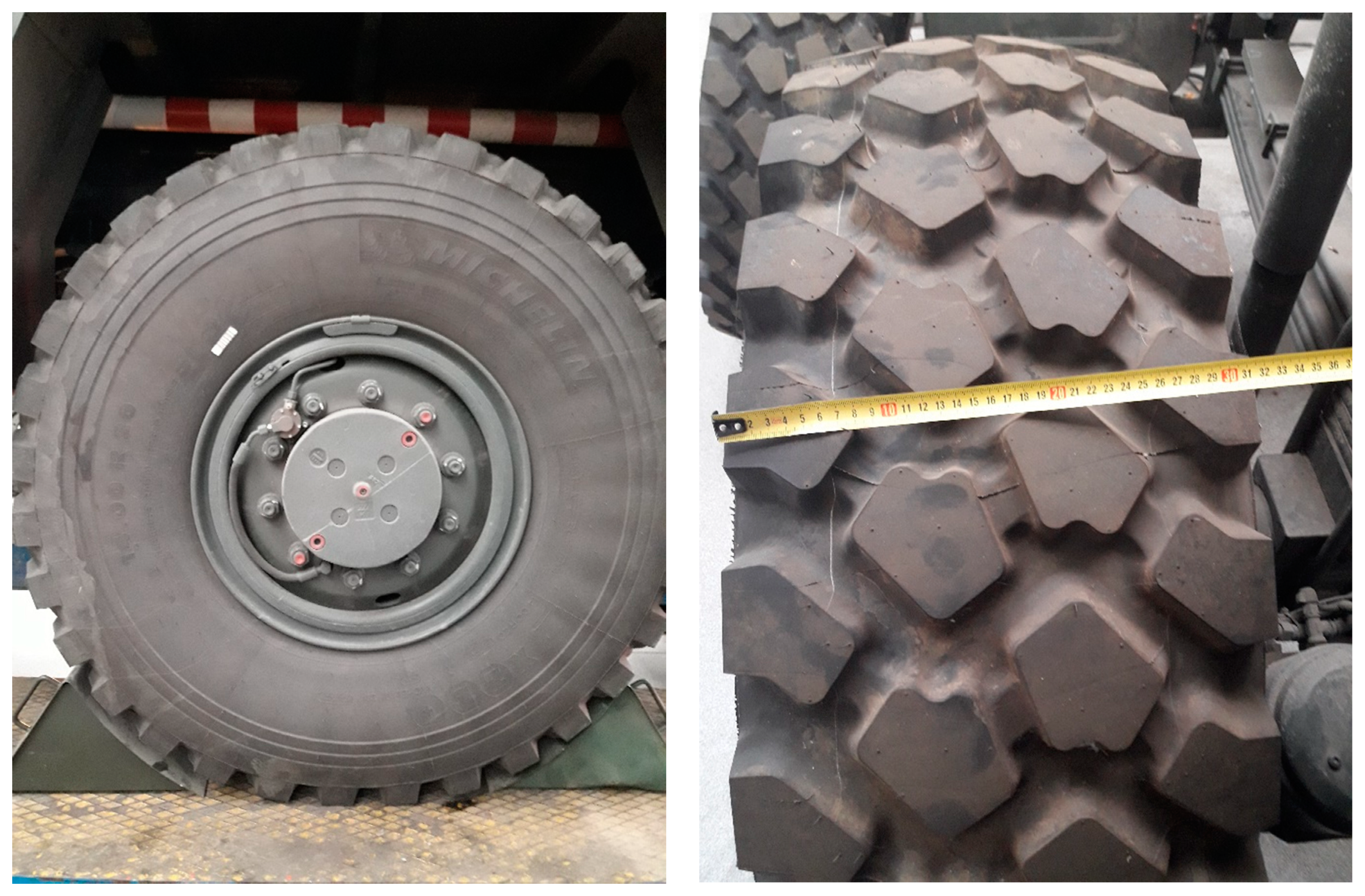
The analyzed vehicle has a 4 × 4 wheeled chassis. The front and rear axles are equipped with 14.00R20XZL tires (rstatic = 629 mm adapted to driving at reduced air pressure. The general view of the tire is shown in Figure 1.
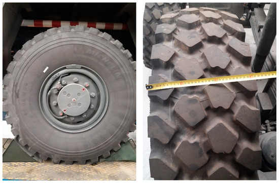
Figure 1.
A general view of the 14.00R20 tire.
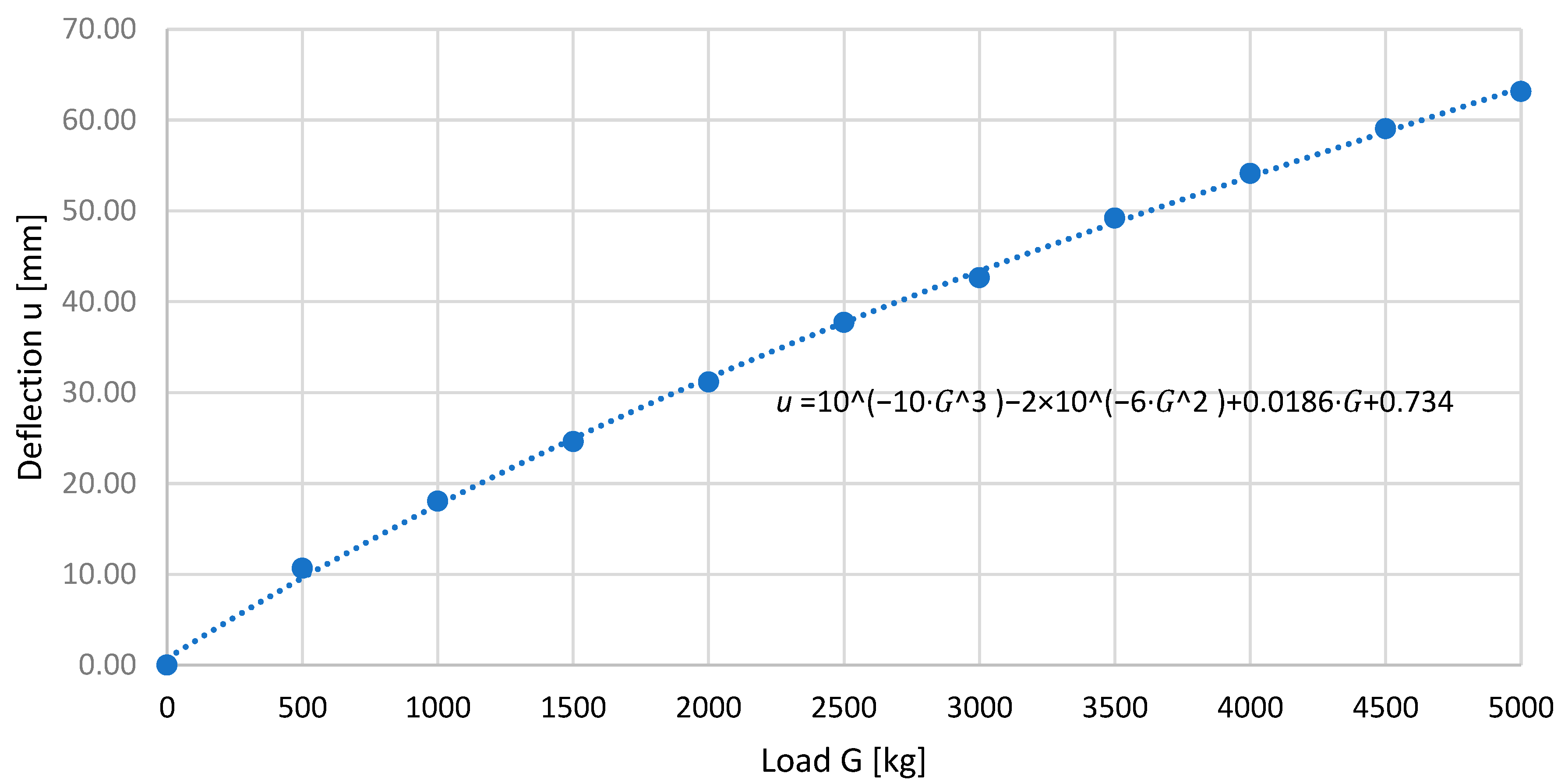
Based on the data from Michelin [13], the tire deflection characteristics, as a function of the external load to the assumed air pressure corresponding to driving on a hard road (p = 6 bar), were determined, obtaining a third-degree polynomial:
where: u is the deflection, (mm) and G is the wheel load, (kg),
The determined polynomial describing the deflection of the tire gives convergent results with the characteristics presented in Michelin’s data [13] in the load range of 0 to 5000 kg, as shown in Figure 2.
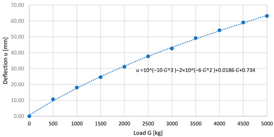
Figure 2.
The characteristics of the tire deflection (u) as a function of load (G) at the inflation pressure (p = 6 bar).
The deflection characteristics of the analyzed tire [14] are comparable with the values obtained by other research teams when testing a tire of the same size but from a different manufacturer [15,16].
2.2. The Characteristics of Spring Elements in the Vehicle Suspension
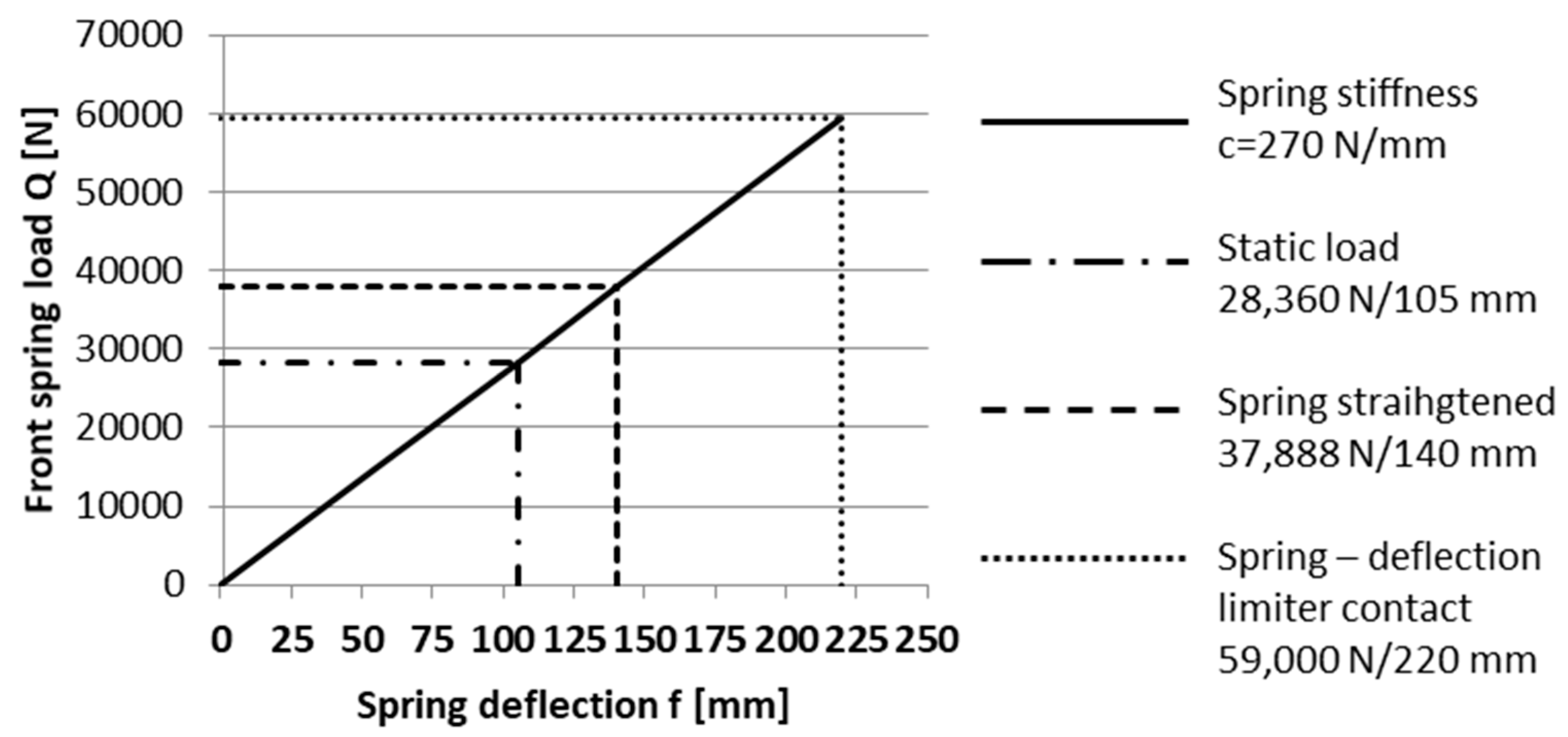
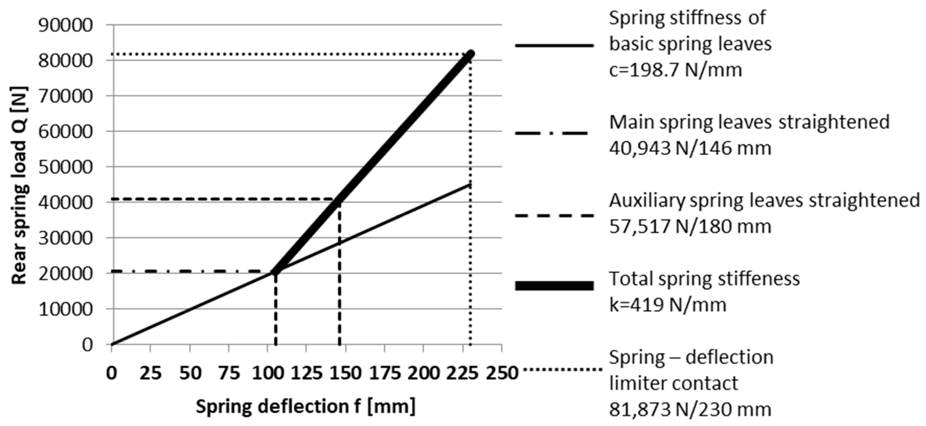
The spring elements in the suspension of the front and rear axles are parabolic springs with the stiffness characteristics presented in Figure 3 and Figure 4.
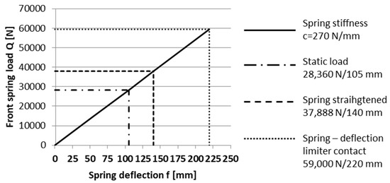
Figure 3.
The characteristics of the stiffness of the 4-leaf parabolic spring of the front axle [17].
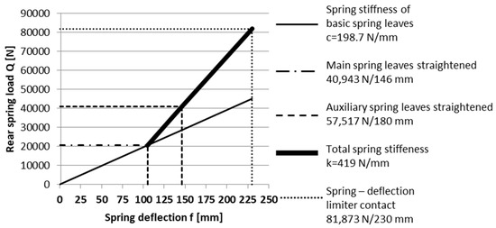
Figure 4.
The stiffness characteristics of the 5-leaf parabolic spring of the rear axle [17].
To limit the angular displacements of the mass sprung, stabilizers were used, the geometrical characteristics of which are presented in Table 1.

Table 1.
The geometric dimensions of the stabilizers.
2.3. The Characteristics of the Vehicle Axle Suspension and Driveline
In the dependent suspension of the rigid driving axles of the vehicle, additional longitudinal rods are not used, which fixes the angular position of the driving axles in relation to the vehicle frame. Instances of braking and the driving force resulting from tire-ground contact are transferred to the bearing system through the springs.
The vehicle has a classic drive system in which the engine is located longitudinally in front of the front axle. The 9+1 speed gearbox is directly connected to the engine. The drive shaft with two universal joints goes into a two-gear transfer case (iSR = 1 or 2), equipped with a planet differential with the possibility of locking. In this subassembly, the drive is divided into two power streams and drive shafts with two universal joints transferred to the rigid driving axles with the main gear (iMN = 1.688) and further to the reduction planetary gears in the wheel hubs (iZ = 3.556) (see Figure 6). The characteristics of the gear ratios and vehicle speed are presented in Table 2.

Table 2.
The characteristics of vehicle movement speed, depending on the gear engaged.
3. The Characteristics of the Cooperation of Selected Vehicle Components
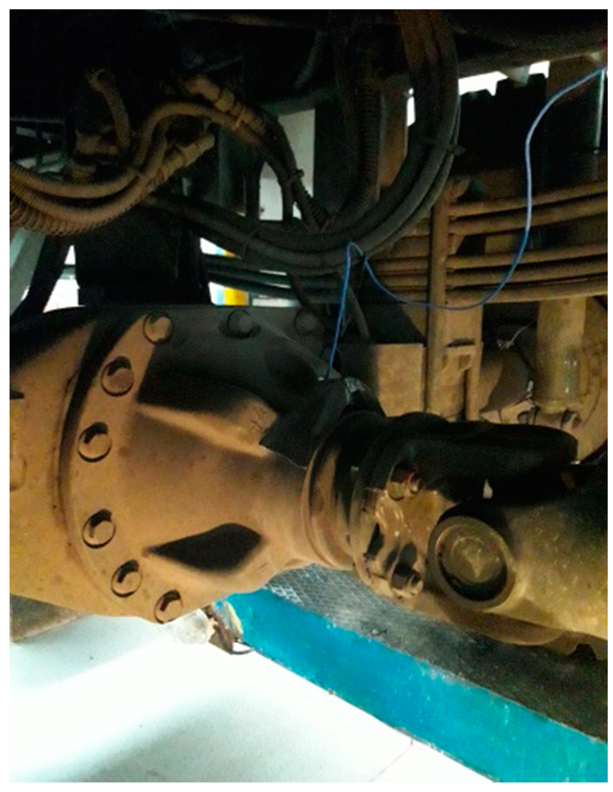
The mutual spatial arrangement and the method of mounting the components of the driveline and the undercarriage with the suspension should be designed in an appropriate way to prevent their mutual displacement from being caused by loads from the transported cargo and traffic conditions that would interfere with their proper cooperation. This task is difficult to achieve in practice as it requires the adoption of many design constraints, the use of complex systems of axle guidance relative to the body, the introduction of additional pivot points into the suspension system, and an increase in the unsprung mass. For practical reasons, design solutions are used to position these components in a way that allows their non-optimal cooperation, resulting in a minimization of the number of necessary components, a reduction of pivot points and unsprung mass. In the analyzed vehicle, the number of components in the suspension system was reduced to a minimum, i.e., the parabolic springs are both spring elements that guide the front and rear drive axles. While driving, they are subjected to bending in the longitudinal vertical plane, stretching and twisting in the longitudinal axis of the vehicle, and torsion by the driving and braking torque acting in the axis of rotation of the wheels of each driving axle. Figure 5 shows a fragment of the left rear suspension with the pinion housing and universal joint.
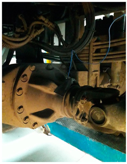
Figure 5.
The pinion housing with a visible universal joint and with elements of the rear axle suspension (the joint is offset from the wheel rotation axis rt = 430 mm).
3.1. The Model of Cooperation between the Propeller Shaft, Transfer Case, and Main Gear
The diagram of the vehicle driveline is shown in Figure 6. In the analyzed vehicle, the position of the engine with the gearbox and transfer case can be considered constant (slight displacements are possible due to the flexibility of the elastic cushions in the supports). The axis of rotation of the output shaft from the gearbox and the axis of rotation of the input shaft to the transfer case are parallel, and their mutual shift causes the sections of the main drive shaft WG to collapse by angles δ1 = δ2 = 2° while maintaining the consistency of the inclination angles δ1 and δ2: SB (t) = SR (t).
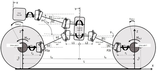
Figure 6.
A diagram of the driveline system.
Figure 6.
A diagram of the driveline system.
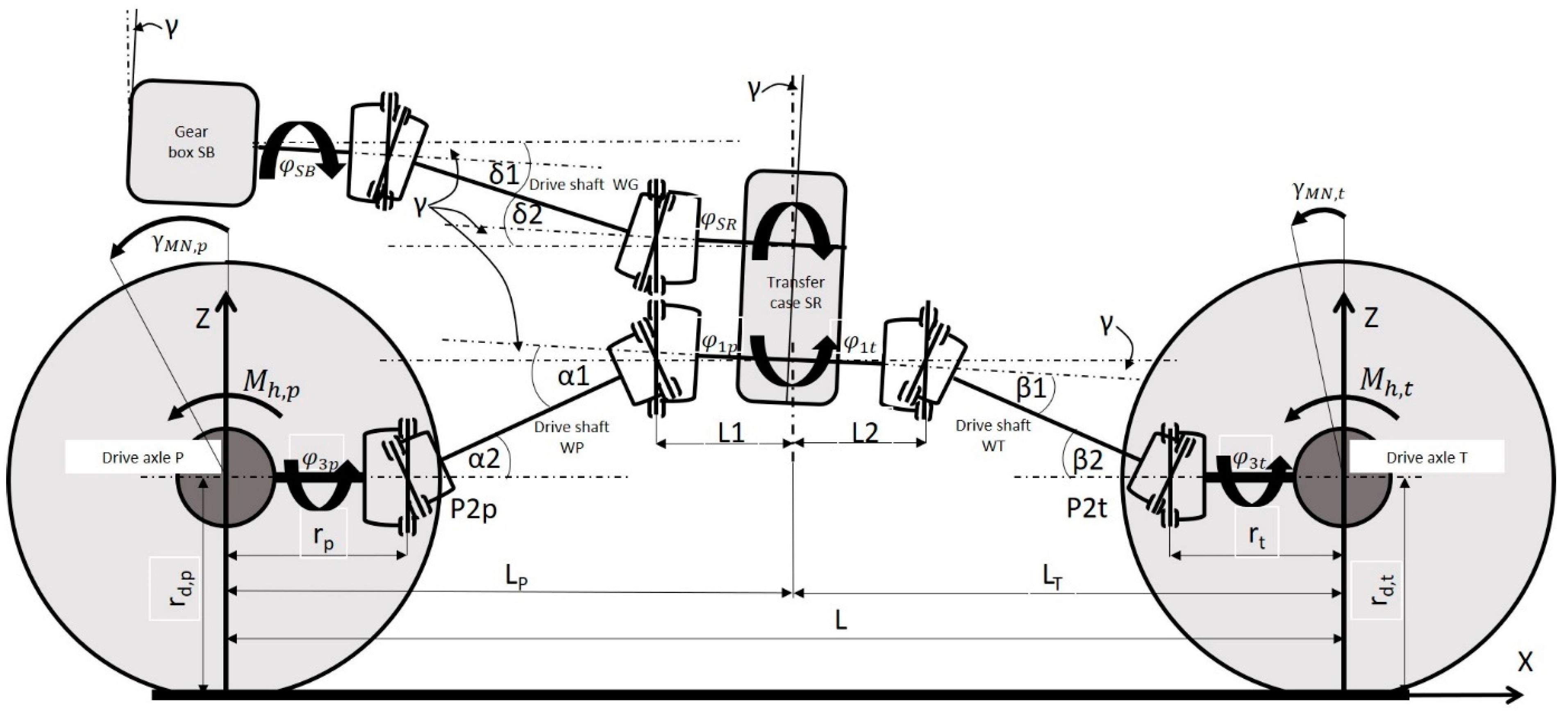
The drive shafts, front WP and rear WT transfer the power flows, which are distributed in the SR transfer case, to the front and rear axle drive wheels via main gears and hub reduction gears.
A properly designed driveline should ensure the compliance of the angular speeds of the output shafts from the transfer case and input shafts to the main gears in driving axles over time, that is:
The condition of compliance of the values of the angles of rotation of the shaft members as well as and as well as is described by the relationship:
If , is and if , is . However, if the position of the WP and WT drive shaft members changes while driving, and as well as , then the condition of compliance of the angular velocities is not met, and so, the phenomenon of kinematic incompatibility arises.
To determine the degree of kinematic incompatibility of the drive shaft WP and WT, it is necessary to know the relationship between the angular velocity of the driving and driven element, which is obtained by differentiating the relationship (3) over time. Taking into account the relationship between the angles of rotation of both members:
getting:
which allows for determining the gear ratio of the WP drive shaft:
The same is done in the case of determining the relationship describing the kinematic incompatibility of the WT shaft. By analyzing the dependence (5), it is apparent that the formation of kinematic incompatibility caused by the operation of drive shafts depends on the values of the instantaneous angles of inclination of the shaft members and .
3.2. The Identification of the Values of Inclination Angles of the Drive Shafts
For the initial analysis of the occurrence risk of kinematic incompatibility in the vehicle driveline system, it is necessary to know the range of changes in the values of the inclination angles as well as to the selected conditions of motion. Figure 6 shows a schematic mutual distribution of the analyzed components, and the numerical data for the values included are summarized in Table 3.

Table 3.
The input data for the distribution of selected vehicle components (vehicle without load).
This assumes that the relative position of the vehicle components, corresponding to a situation when the vehicle is motionless and unloaded, is shown in Figure 6. The sprung mass (mr) is 6936 kg, on the front axle springs (mp) is 4468 kg, and on the rear axle springs is (mt) 2468 kg. Assuming that the unsprung mass of the front axle (mnp) is 1264 kg, and the unsprung mass of the rear axle (mnt) is 1364 kg. The spring deflection corresponding to this load can be determined from the relationship:
where: g is the acceleration due to gravity (m/s2), cp,t is the spring stiffness of the front (p) and rear (t), respectively (N/mm) (Figure 3 and Figure 4),
In the static conditions, the front spring deflection is hp = 81.2 mm, and ht = 60.9 mm.
When the vehicle is loaded with a load of 6000 kg, part of this mass, Δmp = 997 kg, can act on the front axle, and Δmt = 5003 kg acts on the rear axle (depending on the type of load distribution) [18]. Additional front spring deflection (Δhp) and rear spring deflection (Δht ) are, respectively: Δhp = 18.1 mm, and Δht = 81 mm. This additional deflection of the springs leads to the inclination of the body in relation to the transverse axis of the vehicle by tilt angle (°), which can be determined as:
where: L is the wheelbase of the vehicle, L = 4100 mm.
The body tilt angle due to an additional 6000 mass kg under static conditions is −0.6°.
During the movement of the vehicle, as a result of braking, the front and rear drive axles partially rotate, and both the front and rear springs are deflected. This additional spring deformation, caused by the inertia of the car body, depends on the position of the center of the sprung mass of the vehicle and the braking deceleration that occurs. The coordinates describing the position of the center of the sprung mass of the unladen vehicle are X = 1460 mm behind the front axle at a height of Z = 1230 mm [18]. Assuming that the 6000 kg load is distributed over the front axle, Δmp = 997 kg, and rear axle, Δmt = 5003 kg, respectively, and that the center of this mass is at a height of Z1 = 1750 mm, then the coordinates of the center of the sprung mass of the whole laden vehicle can be calculated from the relationship:
After substituting the values, we get XCOG = 2330 mm and ZCOG = 1430 mm. The coordinates of the location of the vehicle’s center of mass are presented in Table 4.

Table 4.
The coordinates of the location of the center of mass of the vehicle in different load variants.
Having the designated coordinates of the position of the center of mass of the vehicle with a mass of 6000 kg and assuming the value of the coefficient of adhesion of the tires to the ground ( while braking, the change in the spring load during braking and the maximum wheel turning moment can be determined.
The range of spring load changes during braking resulting from the inertia force of the car body can be determined based on the relationship:
where: is the inertial force, (N), is the geometric ratio resulting from the height of the center of mass of the body () the wheelbase of the vehicle (L), , and the sprung mass of the laden vehicle ( kg. After substituting the values, we get kN.
Ultimately, a vertical force will act on the front axle springs as the laden vehicle brakes (:
and on the rear axle springs (:
After substituting the values, we get kN and kN. These loads cause an additional deflection of the springs in the front and rear axles. The value of this additional deflection of one spring in the front axle is Δhpb = 57.4 mm and in the rear axle deflection of one spring Δhtb = −37 mm.
The maximum wheel turning moment causing an angular displacement of the axles and can be determined from the dependence:
where: is the dynamic radius of the front and rear wheels, respectively, and is the total weight of the front and rear tires:
Assuming that the nominal pressure in the tire is p = 6 bar, the dynamic radius during braking will change correspondingly for the front wheel (with dependents 1): , . Ultimately, during braking, the dynamic radius of the front axle wheels is: mm, and of the rear axle wheels is: mm. The maximum turning torque of the front axle wheels may reach the value (assuming the brakes can transfer more torque):
and for the rear axle wheels:
Knowing the maximum values of the braking moments of the wheels of individual axles, the range of angular displacements of the driving axles can be determined: and .
It can be assumed that the acceleration and braking of the vehicle cause the parabolic spring to wind up, and its bending can be approximated by a beam model with uniform bending strength. Then the angle of rotation of the drive axle ( can be determined from dependences [19]:
where: is the spring stiffness, N/m, is the spring length, m, and 2 is the two springs.
Substituting the values, the determined angles of spring deformation, which translate into the rotation of the driving axles, are as follows: ° and °.
The rotation of the rigid axles will also displace the universal joints connecting the middle sections of the driven shafts with the pinion shafts of the final drive. Assuming that the displacement in the vertical axis is approximately equal to the arc length corresponding to the rotation of the swing bridge, the value of this displacement can be determined from the relationship:
where: is the distance of the joint of the pinion shaft from the axis of rotation of the driving axle, of the front (p) and rear (t), respectively, is the angle of rotation of the driving axle (in degrees) of the front (p) and rear (t), respectively. Assuming that rp = rt = 430 mm, we get: hpu,p = 37 mm and hpu,t = −31 mm. A collective list of displacements of selected subassemblies and changes in the angle of inclination of sections of the drive shafts is presented in Table 5.

Table 5.
A summary of component displacement values during vehicle braking.
4. An Analysis of Kinematic Incompatibility in the Driveline
Based on the data on the relative position of the vehicle components, selected values are shown in Table 3 and the relative displacements of subassemblies to selected motion conditions are summarized in Table 5, the values of kinematic ratios of the WP and WT drive shafts were determined (5). Thus assumes that the goal to achieve was the compatibility of the angles and depending on the values of the initial angles γMN,p0 and γMN,t0 to the selected conditions of motion. The selection of traffic conditions for analysis was subjective; it was limited to the case of vehicle movement on a road with an asphalt surface (the most common traffic case) when the road surface is relatively flat and the coefficient of tire adhesion to the road surface achieves high values. For these conditions, the cases where the relative linear and angular displacements of the driveline and suspension components would reach the highest values were investigated. It is known from experience that vehicle acceleration achieves values much smaller than deceleration during braking. Hence, the force of inertia causing shifts in position is greater during braking. In addition, it was assumed that the vehicle can be driven without a load or with a load distributed as recommended in the user manual. On this basis, four cases of motion were selected, to which the displacements and their effect on the value of kinematic incompatibility were determined relatively. The figures are summarized in Table 6, Table 7, Table 8 and Table 9, and the corresponding graphs show the variability of the value of the kinematic incompatibility as a function of the rotation of the shaft driving members in Figure 7, Figure 8, Figure 9 and Figure 10.
The values of gamma angles have been calculated from the mathematical models presented above for cases where there is an equal value of alpha and beta angles (in that case there is no kinematic incompatibility). In some cases, it was possible to determine the values of gamma angles for more than one case of motion. This has been indicated in the shaded cells of the tables. For example, Table 6 shows that for γMN,p0 = −2 there is no kinematic incompatibility when the vehicle is in static conditions (with and without load or moving at a constant speed in rectilinear motion).

Table 6.
A set of values of angles of inclination of shafts to the assumed motion conditions due to the value of angles γMN,p0 = −2 (Figure 7a) and γMN,t0 = −2 (Figure 7b).
| ΔiWPmax = 1.10% | γMN,p0 = −2 | γMN,t0= −2 | ||
|---|---|---|---|---|
| ΔiWTmax = 3.19% | α1 [°] | α2 [°] | β1 [°] | β2 [°] |
| Vehicle without load, static conditions | 9.0 | 9.0 | 3.0 | 3.0 |
| Vehicle with load, static conditions | 8.2 | 8.2 | −0.6 | 3.4 |
| Vehicle without load, braking | 6.7 | 3.0 | 5.1 | 10.9 |
| Vehicle with load, braking | 4.2 | −0.8 | 2.4 | 10.5 |
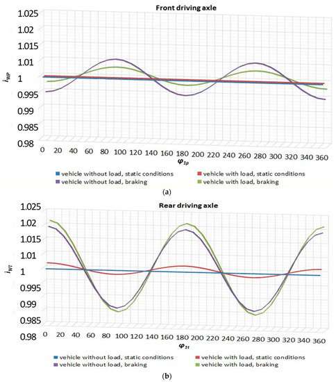
Figure 7.
(a) iWP(φ1p) when γMN,p0 = −2. (b) iWT(φ1t) when γMN,t0 = −2.
Figure 7.
(a) iWP(φ1p) when γMN,p0 = −2. (b) iWT(φ1t) when γMN,t0 = −2.
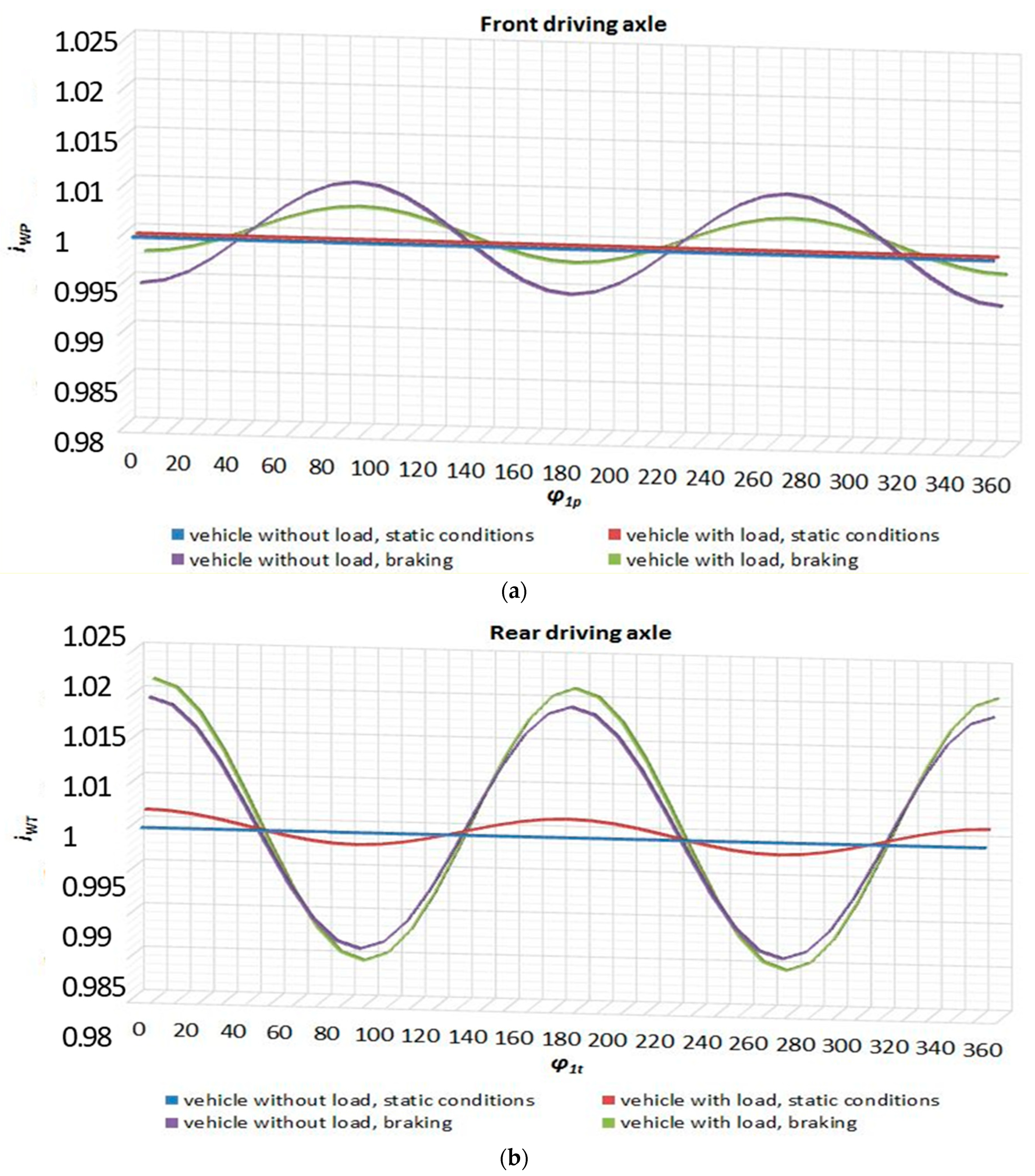

Table 7.
A set of values of angles of inclination of shafts to the assumed motion conditions due to the value of angles γMN,p0 = −2 and γMN,t0 = 2 (Figure 8a) or 0.8 (in parentheses) (Figure 8b).
| ΔiWPmax = 1.10% | γMN,p0 = −2 | γMN,t0= 0.8 or (2) | ||
|---|---|---|---|---|
| ΔiWTmax = 1.63% for 0.8 or 1.22 for (2) | α1 [°] | α2 [°] | β1 [°] | β2 [°] |
| Vehicle without load, static conditions | 9.0 | 9.0 | 3.0 | 5.8 (7.0) |
| Vehicle with load, static conditions | 8.2 | 8.2 | −0.6 | 0.6 (−0.6) |
| Vehicle without load, braking | 6.7 | 3.0 | 5.1 | 8.1 (6.9) |
| Vehicle with load, braking | 4.2 | −0.8 | 2.4 | 7.7 (6.5) |
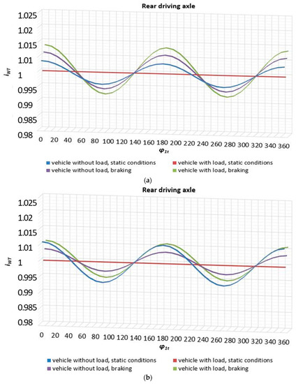
Figure 8.
(a) iWT(φ1t) when γMN,t0 = 0.8. (b) iWT(φ1t) when γMN,t0 = 2.
Figure 8.
(a) iWT(φ1t) when γMN,t0 = 0.8. (b) iWT(φ1t) when γMN,t0 = 2.
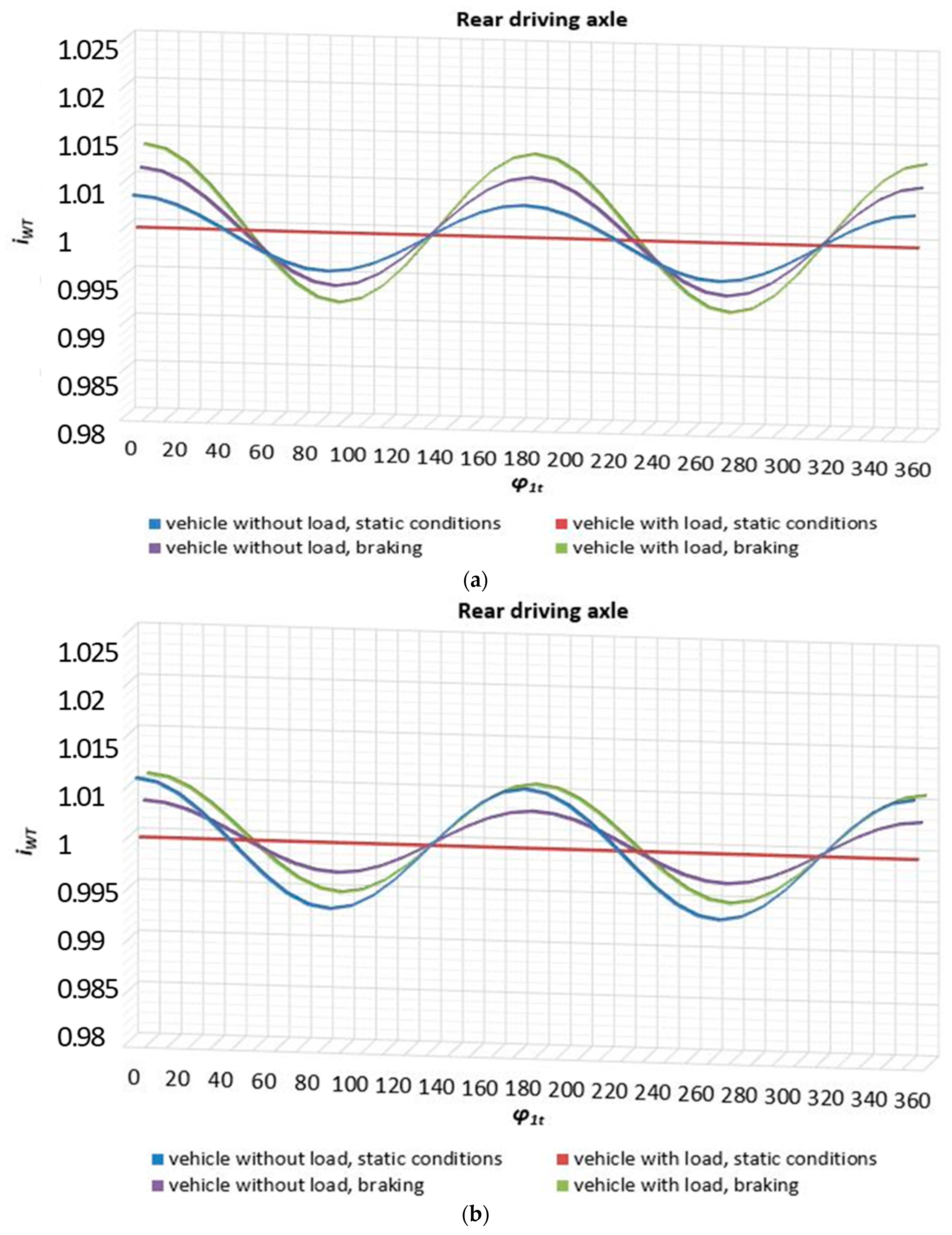

Table 8.
Set of values of angles of inclination of shafts to the assumed motion conditions due to the value of angles γMN,p0 = −5.7 (Figure 9a) and γMN,t0 = 3.8 (Figure 9b).
| ΔiWPmax = 2.47% | γMN,p0 = −5.7 | γMN,t0= 38 | ||
|---|---|---|---|---|
| ΔiWTmax = 2.09% | α1 [°] | α2 [°] | β1 [°] | β2 [°] |
| Vehicle without load, static conditions | 9 | 12.7 | 3 | 8.8 |
| Vehicle with load, static conditions | 8.2 | 11.9 | −0.6 | −2.4 |
| Vehicle without load, braking | 6.7 | 6.7 | 5.1 | 5.1 |
| Vehicle with load, braking | 4.2 | 2.9 | 2.4 | 4.7 |
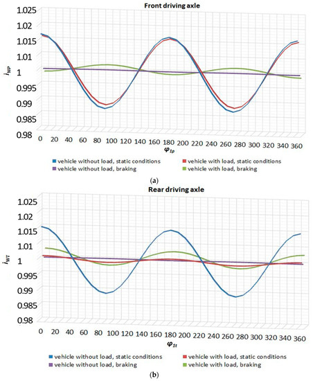
Figure 9.
(a) iWP(φ1p) when γMN,p0 = −5.7. (b) iWT(φ1t) when γMN,t0 = 3.8.
Figure 9.
(a) iWP(φ1p) when γMN,p0 = −5.7. (b) iWT(φ1t) when γMN,t0 = 3.8.
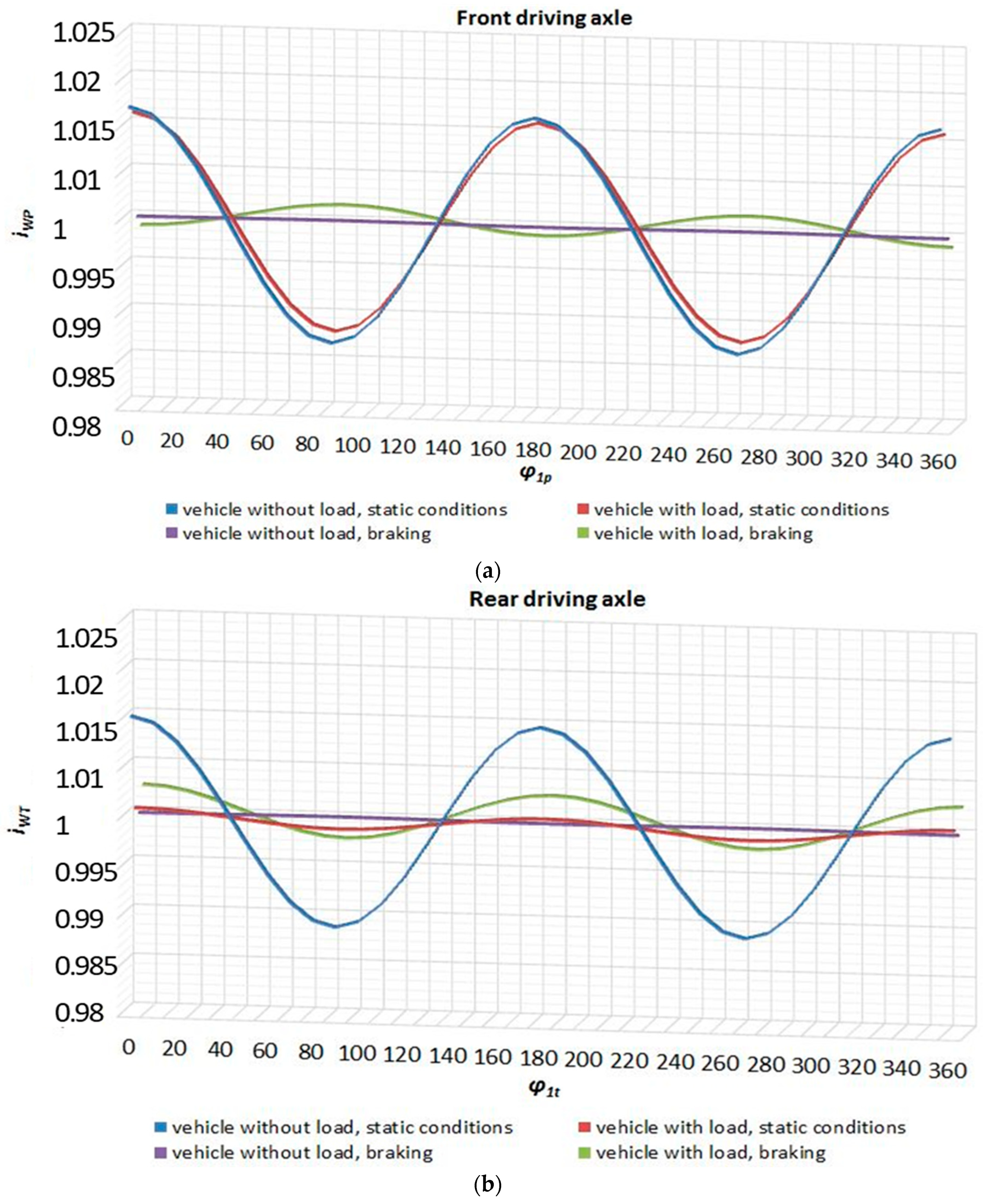

Table 9.
Set of values of angles of inclination of shafts to the assumed motion conditions due to the value of angles γMN,p0 = 1.4 (Figure 10a) or (−7) (Figure 10b) and γMN,t0 = 6.1 (Figure 10c).
| ΔiWPmax = 1.52% for (1.4) or 3.55 for (−7) | γMN,p0 = 1.4 (−7) | γMN,t0= 6.1 | ||
|---|---|---|---|---|
| ΔiWTmax = 3.50% | α1 [°] | α2 [°] | β1 [°] | β2 [°] |
| Vehicle without load, static conditions | 9 | 5.6 (14) | 3 | 11.1 |
| Vehicle with load, static conditions | 8.2 | 4.8 (13.2) | −0.6 | −4.7 |
| Vehicle without load, braking | 6.7 | −0.4 (8.0) | 5.1 | 2.8 |
| Vegicle with load, braking | 4.2 | −4.2 (4.2) | 2.4 | 2.4 |
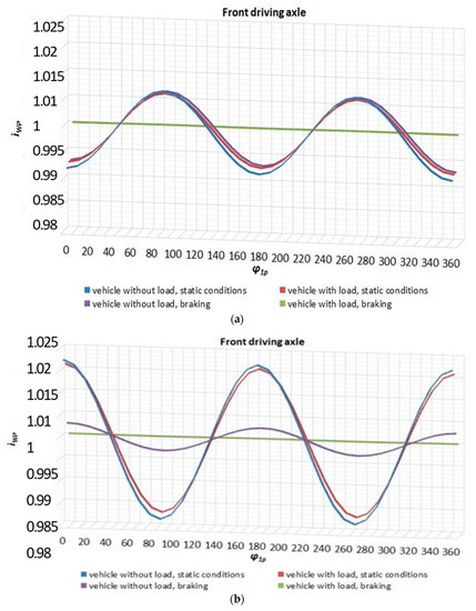
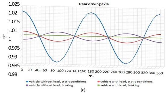
Figure 10.
(a) iWP(φ1p) when γMN,p0 = 1.4; (b) iWP(φ1p) when γMN,p0 = −7. (c) iWT(φ1t) when γMN,t0 = 6.1.
Figure 10.
(a) iWP(φ1p) when γMN,p0 = 1.4; (b) iWP(φ1p) when γMN,p0 = −7. (c) iWT(φ1t) when γMN,t0 = 6.1.
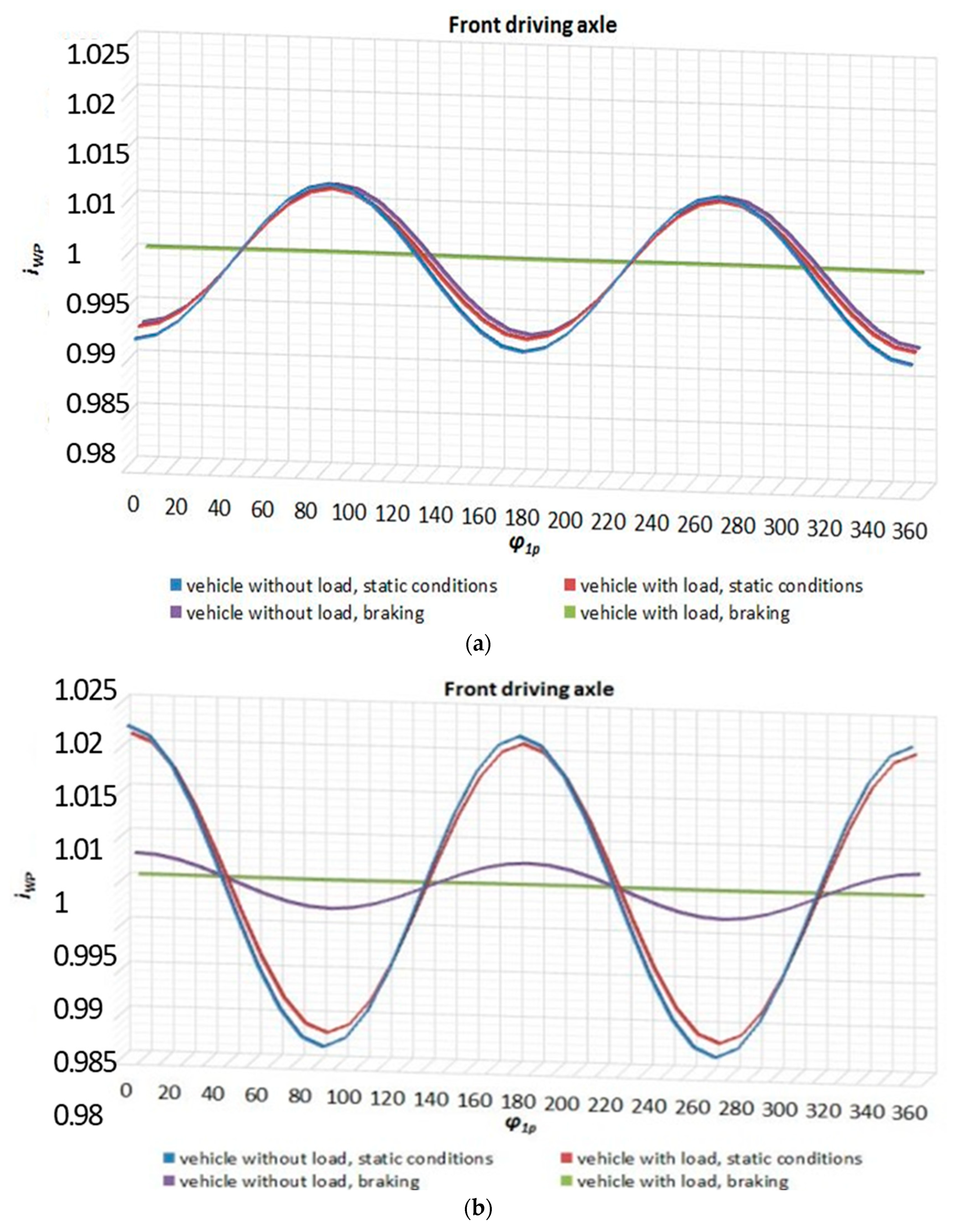
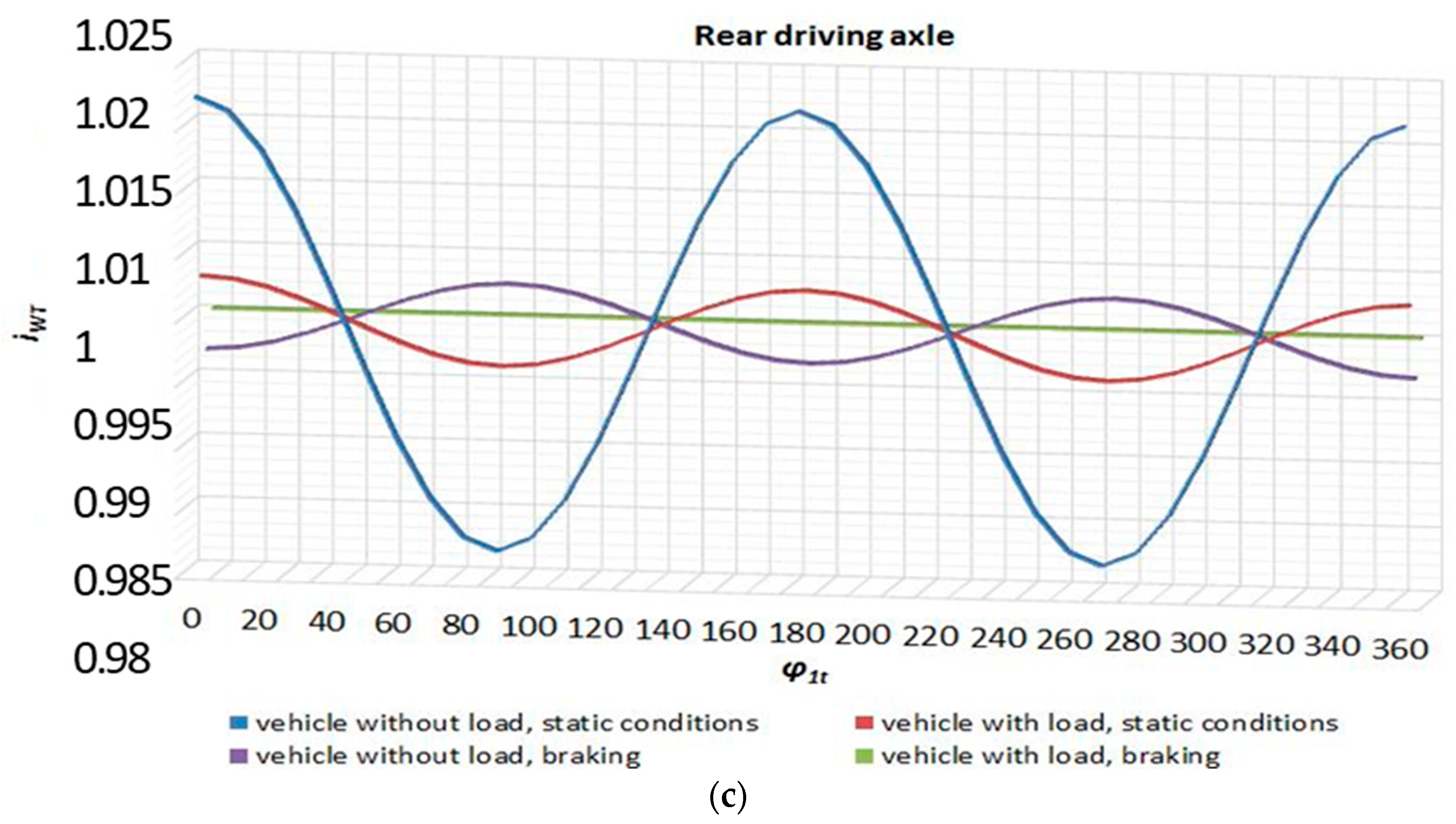
Based on the determined values of the kinematic ratio of the WP and WT drive shafts, depending on the angle of the initial rotation of the drive axle, when looking at γMN,p0 and γMN,t0 respectively, it can be seen that the smallest range of changes of the kinematic gear ratio of the shaft WP occurs when γMN,p0 = −2 (ΔiWPmax = 1.10%) and for shaft WT, when γMN,t0 = 2 (ΔiWTmax = 1.22%). At the same time, it should be noted that regardless of the angular settings of the driving axles, there is always a kinematic incompatibility in the drive system. The possibility of determining the correct initial value of gamma angles γMN,p0 and γMN,t0 for the analyzed type of vehicle suspension was limited only to selected traffic conditions. It is obvious that the selected conditions of vehicle movement and the kinematic incompatibility resulting then do not cover all possible cases. It can be pointed out that when driving loaded in cross-country and off-road conditions, there are large and more complex relative displacements of chassis and driveline components and thus significant kinematic incompatibility, which could lead to the formation of circulating power, which is a very unfavorable phenomenon.
5. Summary
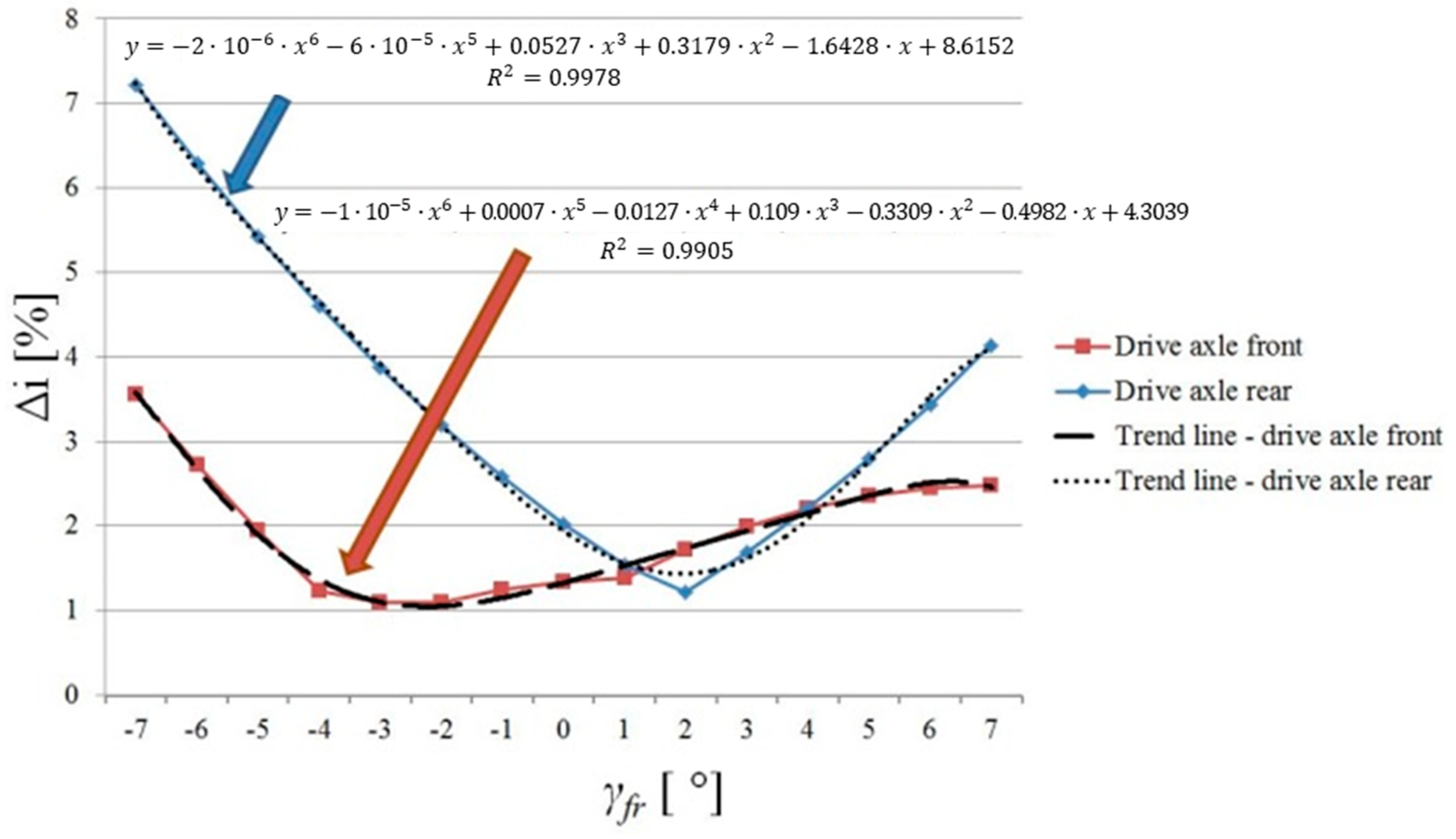
This article presents a mathematical model describing the cooperation of key components in the driveline system of a high-mobility wheeled vehicle, Jelcz 442.32, due to the possibility of the phenomenon of kinematic incompatibility. The analysis uses a model of cooperation between the propeller shaft and two universal (Cardan) joints and the conditions for the correct operation of this component. The indicator of the correct operation of the driveline was the value of the kinematic ratio, which in the entire range of anticipated working loads of the vehicle (use of the vehicle load capacity) should be equal to 1, regardless of the permissible vehicle motion conditions. The analysis considers the load distribution caused by the selected (unfavorable) method of load distribution, causing temporary vertical displacements of the driving axles, and their rotations, resulting from the value of the maximum braking torque of the wheel, taking into account the change in the dynamic radius of the front and rear tires. It has been demonstrated that the smallest change in the kinematic ratio in the driveline system should occur when the initial angle of rotation of the front drive axle is equal to γMN,p0 = −2 (ΔiWPmax = 1.10%), and the initial angle of rotation of the rear driving axle will be γMN,t0 = 2 (ΔiWTmax = 1.22%). It is also observed that a small change in the value of these angles has a large effect on changing the value of the kinematic ratio. The range of changes in the setting of the initial value of the gamma angles and the impact on the resulting kinematic incompatibility in the driveline is shown in Figure 11. The sensitivity of the driveline to the formation of kinematic incompatibility due to the gamma angle is particularly high towards the rear axle. A change of the gamma angle by one degree causes a visible increase in the value of the kinematic incompatibility. Less sensitivity occurs to the front axis. Knowledge of this sensitivity allows the vehicle manufacturer to establish internal rules for assessing the quality of the components supplied to the vehicle (especially springs).
Taking into consideration the data analysis in the publications concerning the dynamic loads resulting from the temporary kinematic incompatibility in the vehicle driveline, it follows that even a small value of this incompatibility can lead to significant accelerations of the sprung mass [20]. In addition, it was noted that the correct manufacture of the springs and their correct installation can have a great influence on maintaining the conditions for the correct operation of the drivetrain. Experimental tests of the vehicle driveline would be beneficial to confirm the validity of the claims made in this article.
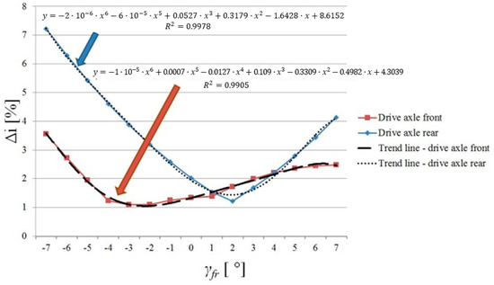
Figure 11.
The range of gear ratio Δi (Equation (5)) as a function of γfr.
Figure 11.
The range of gear ratio Δi (Equation (5)) as a function of γfr.
Author Contributions
Conceptualization, M.K.; methodology, M.K.; validation, M.K.; formal analysis, M.K.; investigation, M.K.; writing—original draft preparation, M.K.; writing—review and editing, P.Z.; visualization, L.G.; supervision, M.K.; project administration, L.G.; funding acquisition, P.Z. All authors have read and agreed to the published version of the manuscript.
Funding
The findings presented in this paper, carried out within the framework of the research project entitled “Model of the system of load identification of the critical element of the suspension system of a high mobility wheeled vehicle of military purpose to the requirements of Health and Usage Monitoring System—HUMS and estimation of Remaning Useful Life—RUL” granted from the pro-quality subsidy for the development of research potential of the Faculty of Mechanical Engineering PWr in the year 2022.
Data Availability Statement
The data presented in this study are available on request from the corresponding author. The data are not publicly available due to military purpose of the research object.
Conflicts of Interest
The authors declare no conflict of interest.
References
- Ministry of Defence. Structure of the Car Fleet of the Polish Armed Forces; Ministry of Defence: Warszawa, Poland, 1999. (In Polish)
- Regulation of the Minister of Transport. Construction and Maritime Economy on the Approval of Motor Vehicles and Trailers and Their Equipment Objects or Parts (Dz.U z 25.09.2015, poz. 1475); Ministry of Transport: Warszawa, Poland, 2015. (In Polish)
- Reimpel, J.; Betzler, J. Automotive Chassis. Fundamentals of Construction; WKiŁ: Warszawa, Poland, 2008. (In Polish) [Google Scholar]
- Wong, J. Terramechanics and Off-Road Vehicle Engineering. Terrain Behaviour, Off-Road Vehicle Performance and Design; Butterworth-Heinemann: Amsterdam, The Netherland, 2010. [Google Scholar]
- Prochowski, L.; Żuchowski, A. Trucks and Buses; WKiŁ: Warszawa, Poland, 2016. (In Polish) [Google Scholar]
- Kosobudzki, M. Speed distribution on road test sections for the need of profile ground testing of special wheeled vehicles. In Proceedings of the XI International Conference on Structural Dynamics, Athens, Greece, 23–26 November 2020; pp. 669–675. [Google Scholar] [CrossRef]
- Browne, M.; Palazzolo, A. Super harmonic nonlinear lateral vibrations of a segmented driveline incorporating a tuned damper excited by a non-constant velicity joints. J. Sound Vib. 2009, 232, 334–351. [Google Scholar] [CrossRef]
- Parszewski, Z. Theory of Machines and Mechanisms; WKiŁ: Warszawa, Poland, 1978. (In Polish) [Google Scholar]
- Kosobudzki, M.; Smolnicki, T. Generalized vehicle durability index for different trafic conditions. AIP Conf. Proc. 2019, 2078, 020017. [Google Scholar]
- MIL-STD-810H; Environmental Engineering Considerations and Laboratory Tests. Department of Defence: Washington, VA, USA, 2019.
- Jamroziak, K.; Kwaśniowski, S.; Kosobudzki, M.; Zajac, P. Analysis of heat exchange in the powertrain of a road vehicle with a retarder. Eksploat. Niezawodn. Maint. Reliab. 2019, 21, 577–584. [Google Scholar] [CrossRef]
- Road Traffic Regulations. Dz.U. 1997, nr 98, poz. 602; Ministry of Transport: Warszawa, Poland, 1997. (In Polish)
- Michelin. Technical Characteristics of Tire 14.00R20XZL+TL164/160J MI. 2014. Available online: https://www.heuver.com/product/b01400020migxzl54/14-00r20-michelin-xzl-complete-on-wheel-164-160g-tl (accessed on 10 February 2023).
- Kulikowski, K.; Szpica, D. Determination of directional stiffenesses of vehicles’ tires under a static load operation. Eksploat. Niezawodn. Maint. Reliab. 2014, 16, 66–72. [Google Scholar]
- Luty, W.; Simiński, P. Analysis of elasticity of radial tyres14.00R20 with Run-Flat insert. Czas. Tech. 2008, 6, 131–138. (In Polish) [Google Scholar]
- Mazzei, A.; Scott, R. Principal parametric resonance zones of a rotating rigid shaft driven through a universal joint. J. Sound Vib. 2001, 244, 555–562. [Google Scholar] [CrossRef]
- Kosobudzki, M.; Stańco, M. Problems in assessing the durability of a selected vehicle component based on the accelearted proving groud test. Eksploat. Niezawodn. Maint. Reliab. 2019, 21, 592–598. [Google Scholar] [CrossRef]
- Operation Manual of Truck Jelcz 442.32; Jelcz Sp. z o.o.: Jelcz Laskowice, Poland, 2016. (In Polish)
- SAE. Spring Design Manual; SAE: Pittsburg, PA, USA, 1990. [Google Scholar]
- Porat, I. Moment transmission by a universal joint. Mech. Mach. Theory 1980, 15, 245–254. [Google Scholar] [CrossRef]
Disclaimer/Publisher’s Note: The statements, opinions and data contained in all publications are solely those of the individual author(s) and contributor(s) and not of MDPI and/or the editor(s). MDPI and/or the editor(s) disclaim responsibility for any injury to people or property resulting from any ideas, methods, instructions or products referred to in the content. |
© 2023 by the authors. Licensee MDPI, Basel, Switzerland. This article is an open access article distributed under the terms and conditions of the Creative Commons Attribution (CC BY) license (https://creativecommons.org/licenses/by/4.0/).

