Article

Modeling of Turbulent Convective Heat-Transfer Characteristics in a Concentric Annular Channel

1
School of Physics, Sun Yat-sen University, Guangzhou 510275, China
2
School of Aeronautics and Astronautics, Sun Yat-sen University, Guangzhou 510275, China
3
Key Laboratory of Icing and Anti/De-Icing, China Aerodynamics Research and Development Center, Mianyang 621000, China
4
Science and Technology on Space Physics Laboratory, China Academy of Launch Vehicle Technology, Beijing 100076, China
*
Author to whom correspondence should be addressed.
Energies 2023, 16(4), 1998; https://doi.org/10.3390/en16041998
Submission received: 17 January 2023 / Revised: 4 February 2023 / Accepted: 9 February 2023 / Published: 17 February 2023
(This article belongs to the Special Issue Modeling and Analysis of Fluid Flow and Heat Transfer)

Abstract

:
Turbulent convective heat-transfer characteristics in a concentric annular channel with both walls heated are theoretically modeled and numerically computed in this article. Generalized algebraic predictive models and equations for heating over a single wall are first reviewed by summarizing the well-known methods in the literature. These methods are then scrutinized according to the most recent investigations such that new viewpoints and corrections are introduced accordingly. Moreover, the application of superposition in temperature is used in the current work instead of the Nusselt number as seen in the literature. The numerical integration method is applied to the generalized equations to obtain the solutions, which are found to be in decent agreement with the direct numerical simulation (DNS) data in the literature. The results in this work also indicate that the wall heat flux density ratio and the annular radius ratio are two key factors that have a great influence on the heat-transfer characteristics of the case with both walls heated.

1. Introduction

Concentric annular channels are widely used in the heat exchangers of nuclear reactors [1], thermal power plants [2], and other engineering fields, owing to the high efficiency in heat transfer. We present a sketch of the annular channel in Figure 1, which is composed of two pipes with one nested into the other. The inner and outer walls of the annular channel, whose radii are defined as a i and a o here, respectively, are usually stationary, and the flow through the channel is driven by an axial pressure gradient d p / d x . When it comes to the case of nuclear heat transfer, a uniform heat flux over the wall can occur as the physical properties are consistent, and the turbulent flow is fully developed. A postulate of the constant heat flux densities over the inner and outer walls, which are defined as q i and q o , respectively, can be used to simplify the associate theoretical modeling [3].
In recent decades, extensive experimental, DNS, and theoretical studies have been preformed to investigate the turbulent heat-transfer characteristics in the annular channel. The earliest method to study the characteristics of turbulent convective heat transfer in the annular channel is experimentation. Krischer et al. [4] investigated the Nusselt number N u in the annular channel with air as the medium under the condition of heating from the outer wall ( q i = 0 ), and found that the annular radius ratio a i / a o can affect the molecular Prandtl number P r and the Reynolds number R e .
Then, Quarmby et al. [5] conducted similar experimental studies for the case of heating from the inner wall ( q i = 0 ). Later, Gnielinski [6] compared these experimental data and found that the characteristic of heat transfer in the annular channel was different between heating from the inner and outer walls with the same P r , R e , and a i / a o . In addition, Kays et al. [7] stated that the characteristics of heat transfer are different with various wall heat flux density ratios q i / q o in the annular channel, although P r , R e , and a i / a o are the same. The recent experimental studies of Wu et al. [8] and Mayer et al. [9] also confirmed that q i / q o has a great impact on the heat-transfer characteristic in the annular channel with both walls heated. This evidence shows that there is a more complex heat-transfer characteristic in the annular channel compared with the round tube or parallel-plate channel.
With the development of modern computer technology, computational fluid dynamics (CFD) has been widely used in the simulation of a wide range of research and engineering problems in fields of study and industries [10,11,12]. As a powerful branch of CFD, direct numerical simulation (DNS) is capable of offering high-fidelity solutions for turbulent flows and, thus, works as an ideal candidate for analysis of the characteristic of heat transfer in the annular channel. The input conditions, such as P r , R e , and a i / a o , can be controlled more strictly in DNS compared with in experiments.
In addition, much more information of the flow field, such as the distribution of the turbulent heat flux density ρ c v T ¯ in the entire cross-section, can be acquired at a higher resolution. Chung et al. [13] investigated the heat-transfer characteristics with R e = 8900 , P r = 0.71 , q i / q o = 1 , and a i / a o = 0.1 and 0.5 , and analyzed the effects of a i / a o . Ould-Rouiss et al. [14] conducted DNS for R e = 14,000, P r = 0.71 , a i / a o = 0.1 , and q i / q o in the range of 0.01 –100, and analyzed the effects of q i / q o .
The distributions of time-averaged temperature T near the wall and the turbulent heat flux distribution in the entire radial direction have been presented in current DNS studies, which provide more detailed information about the characteristics of heat transfer in the annular channel. Later, Ould-Rouiss et al. [15] conducted DNS with R e = 14,000 and 40,000 and indicated that the values of R e had almost no effects on the normalized turbulent shear stress. In the latest DNS studies, Bagheri et al. [16,17,18] analyzed the boundary layer thickness near the inner and outer walls with the change of a i / a o .
It should be noted that the DNS in current literature is conducted for constant physical property, i.e., the density ρ , heat capacity c, molecular thermal conductivity k, and molecular viscosity μ of the flow will be not changed as the temperature changes. Therefore, these DNS data can show the effects of a i / a o , and q i / q o . On this basis, one dedicates to obtain a more general conclusion through the theoretical method about the characteristics of heat transfer in the annular channel to avoid tedious experiment steps or the numerical simulation process.
These works originate from Churchill et al., who proposed a simplified representation of heat transfer in terms of the radial heat flux density q for fully developed flows in round tubes and or parallel-plate channels [19]. On the other hand, the turbulent Prandtl number P r t is used to build relationship between the momentum and energy transfer based on the Reynolds analogy. Following the work of Churchill, Yu et al. [20,21] considered an adaption of the representation in the annular channel and proposed a set of predictions of N u for most of the thermal boundary conditions found in practice: uniform heating on the inner or outer wall, on the both walls, one wall heated and another wall equally cooled, etc.
The predicted values for R e , P r , and a i / a o in a wide range are in good agreement with the experimental data. Furthermore, Yu et al. [22] generalized their works, in which he was concerned about the dependence of N u on P r / P r t and the extension for a parallel-plate channel. In addition, the superposition method mentioned by Yu et al. is applied in the prediction of N u for different thermal boundary conditions from these specific thermal boundary conditions.
The theoretical method has the advantage of less cost, thereby, playing an important role in the prediction of heat-transfer characteristics. However, current theoretical studies are more concerned about the overall heat transfer in the channel. In addition, there should be the more specific analysis about the thermal interaction between the inner wall and the outer wall in the annular channel. Therefore, in this work, we consider turbulent convective heat-transfer characteristics in the concentric annular channel with both walls heated, which is the more general case when compared with a single wall heated.
Most existing theoretical works, as well as the associated analyses, were performed for heating over a single wall. However, our effort in this work is focused on the case of heating over two walls each imposed with an arbitrary constant heat flux density. The predictive models and equations for this case can be obtained by applying the principle of superposition such that the net response of heating over two walls can be related to that of heating over a single wall.
For the modeling, the assumptions herein are taken as follows: (a) The heat flux density on both the inner and outer walls, i.e., q i and q o , are arbitrary constant values. (b) Only single-phase and incompressible flows driven by an axial pressure gradient are considered, and the physical properties of the fluid are constant. (c) The turbulence is fully developed, i.e., R e > 4000 , and thus the variables of the flow field, such as the axial velocity u, and temperature T, are time-mean quantities. The aims of the present work include to obtain the solution of heating over both walls from that of heating over the single wall and then to investigate the effects of a i / a o and q i / q o on the distribution of the turbulent heat flux density.

2. Mathematical Formulation

2.1. Review of the Momentum Transfer in the Annular Channel

There are similarities between momentum and heat transfer since the similar mechanism of turbulent exchange leads to both. In the current literature, this analogy has yielded good results in agreement with the experimental data [23]. For turbulent convective heat transfer in the annular channel with both walls heated, it is easier to summarize the characteristics of momentum transfer than those of heat transfer. Thus, we start this article by considering the characteristics of momentum transfer.
The theoretical work in this article is based on a assumptions of fully developed flow in the channel. When applied in a heat exchanger, this implies that the channel has sufficient length so that the profile of velocity will not change in the axial direction. Therefore, the equation for the conservation of momentum in cylindrical coordinates can be written as
0 = d p d x + 1 r r r μ u r ρ v u ¯ ,
where ρ v u ¯ is described as the turbulent shear stress. The total shear stress τ can be defined as
τ = μ u r ρ v u ¯ = μ + μ t u r ,
where μ t is described as the eddy viscosity. Suggested by Churchill and Chan [19], Equation (2) can be cast in the following dimensionless form
τ τ w = d u + d y + + ( v u ¯ ) + = μ + μ t μ d u + d y + ,
where the dimensionless axial velocity u + = u ( ρ / τ w ) 1 / 2 . The ratio of μ t / μ can be obtained by reformulating Equation (3), yielding
μ t μ = ( v u ¯ ) + τ / τ w ( v u ¯ ) + ,
The terms on the right hand side of the above equation, such as the normalized shear stress τ / τ w and the turbulent shear stress ( v u ¯ ) + = ρ v u / τ w should be determined as a prerequisite for the evaluation of μ t / μ .
For the flow in the annular channel, it should be noted that there is an asymmetric distribution of the velocity in the entire cross-section since the turbulence intensity is higher in the vicinity of the outer wall than in the vicinity of the inner wall [18]. In the same way for the flow in the round tube or parallel-plate channel, the normalized stress stress τ / τ w in the annular channel can be derived after determining the radial position of the zero stress a 0 , which should coincide with the position of the maximum velocity a m based on Equation (3).
However, the earlier experimental and DNS data [24,25] indicates that there are differences between a m and a 0 . Based on this, Kaneda et al. [26] used two different formulas to calculate the values of a 0 and a m , respectively, which is against Equation (3). For this problem, Boersma et al. [27] proposed that it is caused by measurement error in the experimental process or by poor radial resolution of the DNS, and they conducted several DNS experiments with a i / a o = 0.02, 0.04, and 0.1. The DNS data of Boersma et al. indicates that a 0 is coincident with a m .
In recent experimental studies, Marlon et al. [28] presented more accurate measurements through particle image velocimetry for various R e and a i / a o . The experimental data of Marlon et al. agrees with Boersma et al. and indicates that the values of a m , i.e., a 0 , are mainly affected by a i / a o and almost unaffected by R e .
Based on the experimental and DNS data, the characteristics of the velocity distribution and the shear tress distribution in the annular channel is illustrated in Figure 2, where a m denotes the position of the maximum velocity and the zero shear stress and divides the boundary layer into the inner region and outer region. The specific values of a m are evaluated by the empirical expression summarized by Rehme [29], i.e.,
a m a i a o a m = a i a o 0.386 .
Once a m is obtained, the total shear stress τ can be obtained by integrating Equation (1)
τ = d p d x a m 2 r 2 2 r .
The ratios of τ / τ w i and τ w i / τ w o can be represented as
τ τ w i = a i r a m 2 r 2 a m 2 a i 2 ,
τ w o τ w i = a i a o a o 2 a m 2 a m 2 a i 2 .
As aforementioned, the term ( u v ¯ ) + should also be determined in advance for the evaluation of μ t / μ in Equation (4). To obtain the specific expression of ρ v u ¯ , one needs the expression of u. Although the exact distribution of u is not possible to obtain for fully turbulent flows, its necessary structural form can be deduced for the individual regions using dimensional and asymptotic arguments. According to the behavior of u + , the boundary layer in the inner and outer region is assumed to be constituted of two principal regions: the viscous sublayer where the molecular viscosity effect is important and the fully turbulent region where it is not.
For y + 0 , the total shear stress is all viscous, and u + y + . As the y + increases, the influence of the molecular viscosity decreases, until in the fully turbulent region, where the viscosity does not affect the average relative motion u + / y + , and thus the velocity profile can be described by the universal logarithmic law [30]. When considering the annular channel, the velocity profile near the inner and outer walls can, therefore, be approximated in a close formulation based on the DNS data [17].
In addition, the interaction between the inner region and outer region will occur where they intersect, so the terms about the boundary thickness should be considered. For instance, we adopt the representation proposed by Churchill to describe the velocity profile in the annular channel, i.e.,
u 0 + = ( y + ) 2 1 + y + exp [ 1.75 ( y + / 10 ) 4 ] u + = 6.16 + 2.59 ln y + + 3.75 y + a + 2 2.97 y + a + 3
where δ + denotes the dimensionless boundary layer thickness, which is computed by
δ + = ( a m a i ) ( ρ τ w i ) 1 / 2 / μ , for the inner region , ( a o a m ) ( ρ τ w o ) 1 / 2 / μ , for the outer region .
where a m denotes the location of the maximum in the velocity distribution or the zero in the total shear stress as aforementioned. Here, the subscript 0 accounts for the contribution from the viscous sublayer, and from the fully turbulent region. To avoid looking for the specific critical point, a general expression proposed by Churchill and Usagi [31] is applied, i.e.,
( u + ) 3 = ( u 0 + ) 3 + ( u + ) 3 .
Therefore, the specific expressions for the viscous sublayer and fully turbulent region can be obtained, i.e.,
( u v ¯ ) 0 + = 0.7 y + 10 3 τ τ w ( u v ¯ ) + = τ τ w 1 y + δ + 2.59 y + 2.59 y + 1 + 3.89 y + δ +
which can be connected by an expression similar to Equation (11), i.e.,
( u v ¯ ) + 8 / 7 = ( ( u v ¯ ) 0 + ) 8 / 7 + ( ( u v ¯ ) + ) 8 / 7 .

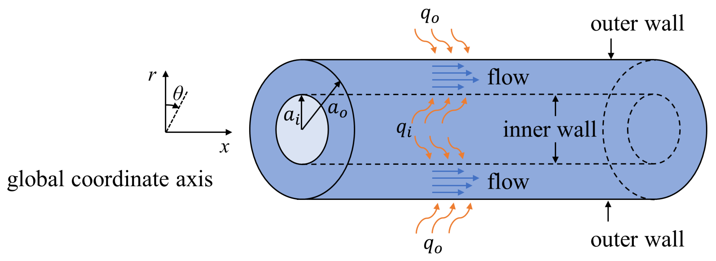
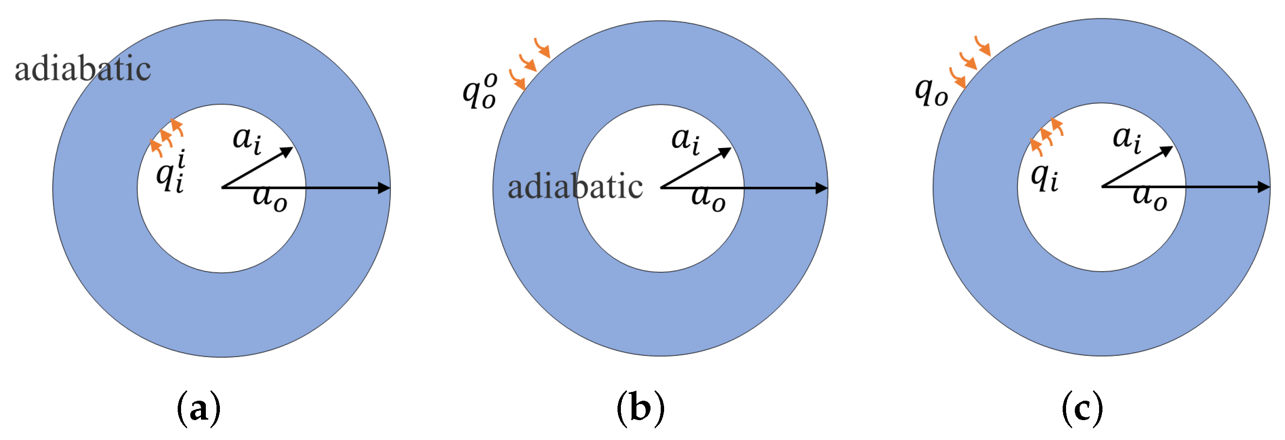
2.2. Analysis of the Heat Transfer in the Annular Channel with Heating over Both Walls

As shown in Figure 3, the heat transfer boundary conditions imposed on the annular channel can be divided into three types: only the inner wall is heated with q i i , as shown in Figure 3a; only the outer wall is heated with q o o , as shown in Figure 3b; and a more general case where both walls are heated with q i and q o , respectively, as shown in Figure 3c. There are sufficiently accurate correlations, which were proposed by Gnielinski, to predict the values of N u for the first two cases in Figure 3 [6].
In addition, Yu et al. [22] discussed the relations between the third case and the first two cases in Figure 3, and proposed a generalized predictive equation in terms of N u for different thermal boundary conditions by applying superposition. The application of superposition, however, requires that the energy equation is linear in temperature. We demonstrate this using strict derivations in the paper and provide a more accurate and detailed predictive equation in terms of the temperature and heat flux density by using superposition.
For fully developed turbulence, the profile of the temperature, i.e., T w T / T w T m , will not change in the axial direction, or T is similar to linear changes. Therefore, the governing equation for the conservation of energy in cylindrical coordinates can be represented as
ρ c u T x = 1 r r r k T r ρ c v T ¯ ,
where the specific boundary conditions for the three cases are given by
k T r r = a i = q i i , k T r r = a o = 0 , heating over the inner wall k T r r = a i = 0 , k T r r = a o = q o o , heating over the outer wall k T r r = a i = q i , k T r r = a o = q o , heating over both walls
In Equation (14), the unknown quantity ρ c v T ¯ is described as the turbulent heat flux density. By introducing the eddy conductivity k t , ρ c v T ¯ can be expressed in the form
ρ c v T ¯ = k t T r ,
and then the radial heat flux density q can be expressed in the form of the Fourier law
q = k + k t T r .
The eddy conductivity k t is caused by turbulence and mainly produces effects in the fully developed turbulent region, which is the similar to eddy viscosity μ t . Therefore, we attempt to establish a contact between the thermal diffusion process and momentum diffusion process caused by turbulence. In the literature, the Reynolds analogy is usually used to investigate the heat-transfer characteristics in the boundary layer, in which the turbulent Prandtl number P r t is described the ratio of momentum to thermal diffusivity, i.e.,
P r t = μ t c k t .
Yakhot [32] evaluated the reliability of this method to predict the temperature distribution, and the solution from this method is in good agreement with the experimental data with P r in the range of 10 2 10 6 .
Here, we used the ratio k t / k to discuss the characteristics of k t , which benefits the analysis of the heat transfer of the more general case shown in Figure 3c and, furthermore, obtains the distribution of ρ c v T ¯ . Therefore, based on Equations (18) and (4), k t / k can be represented as
k t k = P r P r t μ t μ = P r P r t v u ¯ + τ / τ w v u ¯ + .
In this article, a fluid with constant physical properties is discussed, which is applied to the flow with a small temperature difference across the boundary layer. Thus, the molecular conductivity k, molecular viscosity μ , and molecular Prandtl number P r are assumed as constant. As for P r t in Equation (19), Kays [33] showed the characteristics away from the wall through the investigation of experimental and DNS data: it has a maximum value near the wall and tends to be a constant far from the wall.
However, the eddy conductivity k t has little effect on the thermal conduction dominated region near the wall; thus, P r t can be regarded as a constant. Recently, the investigations of Straub et al. [34] and Lei et al. [35] have shown that, for flows with large values of Prandtl number P r , such as air and water, P r t can be further simplified as a function of P r ; for example [36]
P r t = 0.85 + 0.015 P r .
For instance, we use P r = 0.71 for the air in this work [37]. As discussed previously in Section 2.1, the eddy viscosity μ t is evaluated as a complicated function of the radius location r; as a result, k t can be finally formulated as a function of r.
Owing to the characteristics of k t , the energy balance equation (Equation (14)) can be further simplified to a linear partial differential equation. This will facilitate the analysis of the case of heating over two walls by applying the principle of superposition associated with the linear partial differential equation. Motivated by the work of Lundberg et al. [38] on laminar flows, we applied the superposition in terms of temperature for the fully developed turbulent convection in this work
T = T i + T o T e ,
where T, T i , and T o are the temperature distributions for heating over both walls, the inner wall, and the outer wall, respectively. The entrance temperature T e corresponds to the temperature distribution for both walls with zero heat flux density.
It is noted that the heat flux density q and turbulent heat flux density ρ c v T ¯ can be obtained by taking the derivative of the temperature T, and T e can be eliminated as a result, i.e.,
q = q i + q o .
where q i and q o denote the distributions of the flux density obtained for the case of heating over the inner wall only (namely, q i i = q i ) and the outer wall only (namely, q o o = q o ), respectively. For clarification, the coefficient k is a constant, and k t depends on the radius location r only, which means that ( k + k t ) is independent from the three types of boundary conditions in this work. T e in Equation (21) is eliminated after taking the derivative.
Instead of using the original form of Equation (22), we perform the normalization with respect to the heat flux density q i specified at the inner wall, yielding
q q i = q i q i + q o q o q o q i .
Here, it should be noted that q i and q o are specified values, and q i and q o are unknown variables that can be evaluated by considering the case of heating over a single wall. For instance, in view of the case of heating over the inner wall only (namely, q i i = q i ), the radial heat flux density q i can be obtained by integrating Equation (14).
q i = ρ c 2 r r 2 a o 2 u T i x d r 2 .
Then, the heat flux density at the inner wall q i i can be obtain from Equation (24) by setting r = a i , i.e.,
q i i = ρ c 2 a i a i 2 a o 2 u T i x d r 2 = ρ c a o 2 a i 2 u m 2 a i T m i x ,
where the expression of the dimensionless mixed-mean velocity u m + = u m ( ρ / τ w i ) 1 / 2 is given by Kaneda et al. [26], which is
u m + = 1 a o / a i 2 1 1 ( a o / a i ) 2 u + d R i 2 = 3.2 + 2.293 ln ( a o + a i + ) ( a o + a i ) a i a m 2 a i 2 275 ( a o + a i + ) a m 2 a i 2 ( a o + a i ) a i ,
where R i = r / a i .
The research of Churchill et al. [39] shows that, when the heat flux density at the wall is constant, the gradient of the radial temperature in the axial direction is constant for the fully developed turbulence, i.e., T / x = T m / x = T w / x . Therefore, by substituting for Equation (26), Equation (24) can be simplified as
q i q i i = 1 R i [ a o / a i 2 1 ] R i 2 a o / a i 2 u + u m + d R i 2 .
Similarly, the radial heat flux density for the case of heating from the outer wall, i.e., q o / q o o , can be expressed as
q o q o o = 1 R o [ 1 a i / a o 2 ] a i / a o 2 R o 2 u + u m + d R o 2 ,
where R o = r / a o . Thus, q i / q i and q o / q o in Equation (23) can be determined by Equations (27) and (28), respectively.

2.3. The Numerical Method

It is noted that Equation (27) and (28) are integral formulas. Due to their complexity, a numerical method is used for the computation involved. Here, the ratio of q i / q i in Equation (27) is used as an example to illustrate the numerical solution method in this work. First, the expression of q i / q i can be written as
q r = g r r a o + f r d r ,
where r is the radial coordinate, q r = q i / q i , g r = 1 R i a o / a i 2 1 , and f r = u + u m + .
The upper limit a o + in Equation (29) should be determined before calculating the q i / q i , since other quantities, such as a i / a o and R e , are given as input. Based on the definition of a o + , a i + , R e , and u m + , one can build a relationship between them, i.e.,
a o + a i + = R e 2 u m + .
By substitution of u m + with Equation (26),we can construct a Newton iterative formula about a o + a i + , i.e.,
a o + a i + = R e 2 3.2 + 2.293 ln ( a o + a i + ) ( a o + a i ) a i a m 2 a i 2 275 ( a o + a i + ) a m 2 a i 2 ( a o + a i ) a i ,
where the unknown term ( a o + a i ) a i a m 2 a i 2 can be determined using Equation (5). Then, the Newton iterative method is applied to solve the value of a o + a i + , and the specific values of a o + and a i + can be determined for the given a i / a o .
The numerical integration of Equation (29) is performed using the trapezoidal method due to the complexity of u + . The integral interval r n + , a o + is divided into m parts, and the width of the part r m + , r m + 1 + is less than 1 to ensure that the error of numerical integration can be neglected. Then, the integral value of function f ( r ) in r m + , r m + 1 + , i.e., I m , is approximately represented by the area of the trapezoidal, i.e.,
I m = r m + r m + 1 + f r d r 1 2 f r m + + f r m + 1 + · | r m + 1 + r m + | .
It is noted that I m is the difference between the primitive functions r m + 1 + and r m + ; thus, the boundary condition, which is the heat flux density at the outer wall q i a o + , should be determined. Here, we consider the case of the first type in Figure 3, and the outer wall is adiabatic, i.e., q i a o + = 0 .
Then, Equation (28) can be solved in a similar way. Note that the lower limit a i + should be determined, and the boundary condition is the heat flux density at the inner wall, i.e., q o a i + = 0 .

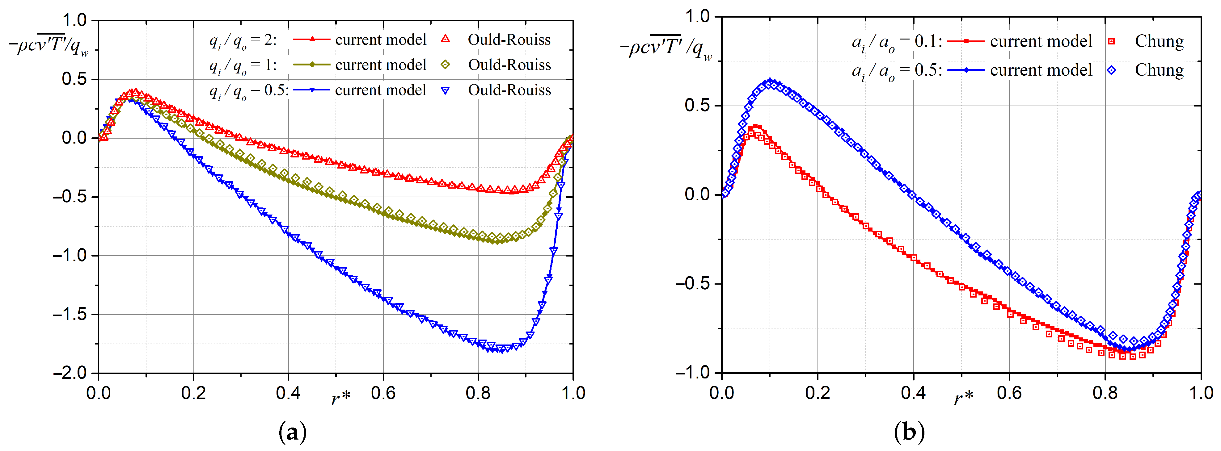
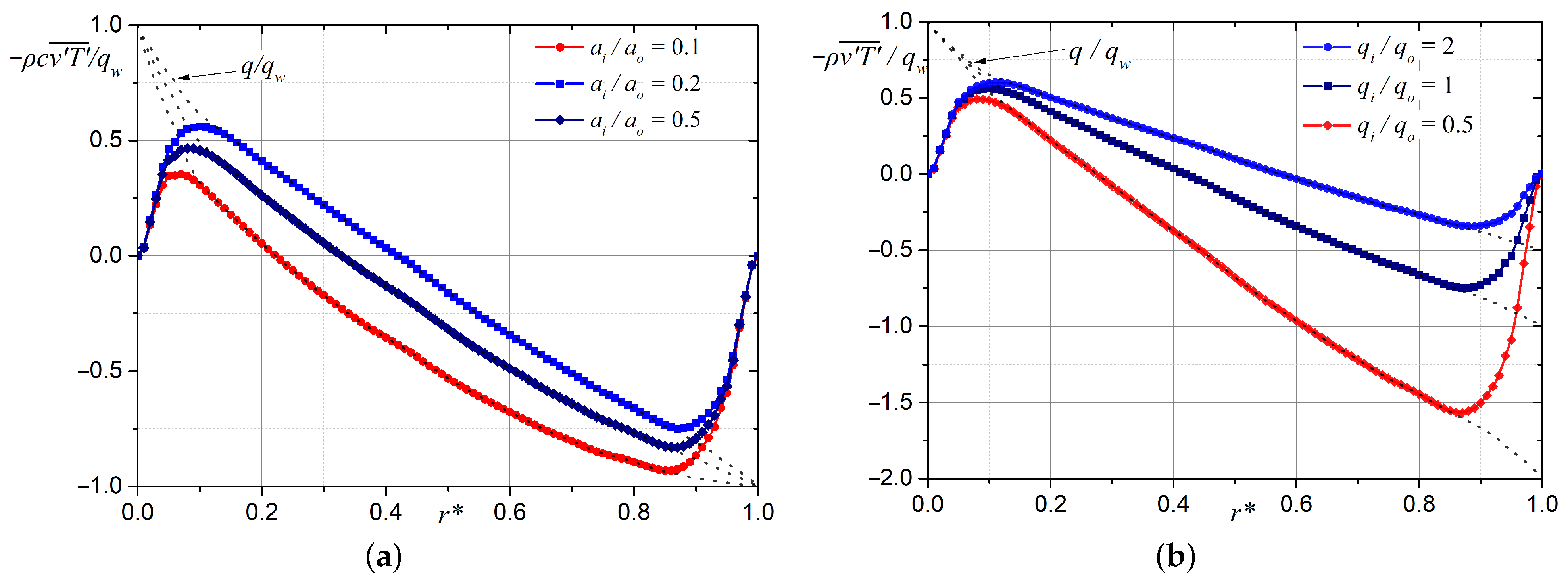
3. The Numerical Results and Analysis

In the previous subsections, the expressions of the normalized radial heat flux density q / q w ( q w = q i for heating over the inner wall and both walls, and q w = q o for heating from the outer wall) are deduced for the three cases. Then, by Equations (18) and (17), the distributions of the normalized turbulent heat flux density ρ c v T ¯ / q w can be obtained by
ρ c v T ¯ q w = 1 1 1 + P r P r t ( v u ¯ ) + τ / τ w ( v u ¯ ) + q q w ,
which is the main quantity used to assess the current model and the heat-transfer characteristics in the annular channel.
For the validation purpose, the solutions of ρ c v T ¯ / q w for heating over both walls predicted in this work are all provided compared with the DNS data of Ould-Rouiss et al. [14] and Chung et al. [13]. Figure 4a illustrates the distribution of ρ c v T ¯ / q w in the entire radial direction for various annular radius ratios a i / a o s ( R e = 8900 , and equal heat flux density on both walls, i.e., q i / q o = 1 ), while Figure 4b shows the distribution of ρ c v T ¯ / q w for various wall heat flux density ratios q i / q o s with a i / a o = 0.1 and R e = 14,000. We found that the distributions of ρ c v T ¯ / q w from this work are all in good agreement with those of the DNS data for various a i / a o s and q i / q o s, thereby, demonstrating the promising performance of the proposed model and the numerical method applied to solve it.
According to Figure 4, the effect of R e on the normalized turbulent heat flux is negligible; thus, the effects of a i / a o and q i / q o on ρ c v T ¯ / q w and q / q w are investigated in this work. The distributions of ρ c v T ¯ / q w and q / q w for a i / a o = 0.1 and 0.5 are shown in Figure 5a ( R e = 10,000). As a i / a o is increased to 0.5 , a point symmetric profile can be obtained, and the point of the zero value approaches the outer wall.
It can be inferred that, when a i / a o = 1 , the inner and outer walls exhibit the same characteristics of heat transfer. The effects of q i / q o are shown in Figure 5b. The distributions of ρ c v T ¯ / q w and q / q w do not exhibit a point symmetric profile as q i / q o increases; instead, it bears resemblance to the case of heating from the inner wall. On the contrary, ρ c v T ¯ / q w and q / q w and with a small q i / q o are similar to the case of heating from the outer wall. It is, therefore, confirmed that the case of heating from the inner/outer wall can be considered as a special case of heating from both walls with a rather high/low wall heat flux density ratio.

4. Conclusions

We theoretically modeled turbulent convective heat-transfer characteristics in a concentric annular channel for heating over both walls, each with an arbitrary constant heat flux density. We demonstrated the linearity of the energy equation in temperature using strict derivations and then proposed more accurate and detailed predictive equations by applying the principle of superposition in temperature. The accuracy of this method was evaluated through a comparison between the solutions predicted herein and the DNS data from the literature.
The numerical results indicate that both the annular radius ratio a i / a o and wall heat flux density ratio q i / q o are two key factors affecting the turbulent heat-transfer characteristics. As a i / a o increases, the inner and outer walls approach identical characteristics of heat transfer. However, for q i / q o , the results reveal a different mechanism such that, at a very high/low heat flux density ratio, heating over two walls works as if only one side wall is heated. The investigation of this work included a comprehensive and accurate analysis of the heat-transfer characteristics in an annular channel, and the results support the theoretical research in the existing literature.

Author Contributions

Conceptualization, L.C. and H.Z.; methodology, H.Z.; software, L.C.; validation, G.W.; formal analysis, H.Z.; investigation, H.Z.; resources, L.C.; data curation, L.C.; writing—original draft preparation, H.Z.; writing—review and editing, H.Z.; visualization, L.C.; supervision, L.L.; project administration, G.W.; funding acquisition, L.L. All authors have read and agreed to the published version of the manuscript.

Funding

This research was funded by National Key Project (No. GJXM92579), Fundamental Research Funds for the Central Universities of Sun Yat-sen University (No. 22QNTD0705), and Open Fund of Key Laboratory of Icing and Anti/De-icing (Grant No. IADL20200306).

Data Availability Statement

Not applicable.

Conflicts of Interest

The authors declare no conflict of interest.

Nomenclature

a          radius of annulus (m)
a m           radius of maximum in velocity (m)
a +           dimensionless radius a ( τ w ρ ) 1 / 2 / μ
c          specific heat capacity ( J · k g 1 · K 1 )
h          heat transfer coefficient ( T w T m ) / q w ( W · m 2 · K 1 )
N u           Nusselt number 2 h ( a o a i ) / k
kmolecular conductivity ( W · m 1 · K 1 )
k t eddy conductivity ( W · m 1 · K 1 )
ptime-averaged pressure ( Pa )
P r molecular Prandtl number μ c / k
P r t turbulent Prandtl number
qradial heat flux density ( W · m 2 )
rradial coordinate (m)
R e Reynolds number 2 a o a i u m ρ / μ
r normalized radial coordinate r a i a o a i
R e Reynolds number 2 a o a i u m ρ / μ
Ttime-averaged temperature (K)
T + dimensionless temperature k ρ τ w 1 / 2 T w T / μ q w
T m mixed-mean temperature 1 u m ( a o 2 a i 2 ) a i 2 a o 2 u T d r 2 (K)
utime-averaged axial velocity ( m · s 1 )
u m mixed-mean axial velocity 1 ( a o 2 a i 2 ) a i 2 a o 2 u d r 2 ( m · s 1 )
u + dimensionless axial velocity u ( ρ / τ w ) 1 / 2
xaxial coordinate (m)
ydistance from the wall (m)
y + dimensionless distance from the wall y ( τ w ρ ) 1 / 2 / μ
δ boundary layer thickness (m)
μ molecular viscosity ( Pa · s )
μ t eddy viscosity ( Pa · s )
ρ molecular density ( kg · m 3 )
ρ v u ¯ turbulent shear stress ( Pa )
ρ c v T ¯ turbulent heat flux density ( W · m 2 )
τ shear stress ( Pa )
( v u ¯ ) + dimensionless turbulent stress ρ v u / τ w
Subscriptwwall
Subscriptipertains to the inner wall
Subscriptopertains to the outer wall
Superscriptiheated over the inner wall only
Superscriptoheated over the outer wall only

References

  1. Nejad, M.Z.; Ansarifar, G. Optimal design of a Small Modular Reactor core with dual cooled annular fuel based on the neutronics and natural circulation parameters. Nucl. Eng. Des. 2020, 360, 110518. [Google Scholar] [CrossRef]
  2. Bai, Y.; Zhao, Z.; Xu, G.; Bai, Y. Heat transfer characteristic analysis of a novel annular nuclear heat exchanger for propulsion system. Ann. Nucl. Energy 2019, 126, 84–94. [Google Scholar] [CrossRef]
  3. Akimoto, H.; Anoda, Y.; Takase, K.; Yoshida, H.; Tamai, H. Nuclear Thermal Hydraulics; Springer: Tokyo, Japan, 2016; pp. 3–14. [Google Scholar]
  4. Krischer, O. Heat transfer in annuli for laminar and turbulent flow. Chem. Eng. Technol. 1961, 33, 13–19. [Google Scholar]
  5. Quarmby, A. Some measurements of turbulent heat transfer in the thermal entrance region of concentric annuli. Int. J. Heat Mass Transf. 1967, 10, 267–276. [Google Scholar] [CrossRef]
  6. Gnielinski, V. Turbulent heat transfer in annular spaces—A new comprehensive correlation. Heat Transf. Eng. 2015, 36, 787–789. [Google Scholar] [CrossRef]
  7. Kays, W.; Leung, E. Heat transfer in annular passages—Hydrodynamically developed turbulent flow with arbitrarily prescribed heat flux. Int. J. Heat Mass Transf. 1963, 6, 537–557. [Google Scholar] [CrossRef]
  8. Wu, Y.W.; Su, G.H.; Qiu, S.Z.; Hu, B.X. Experimental study on critical heat flux in bilaterally heated narrow annuli. Int. J. Multiph. Flow 2009, 35, 977–986. [Google Scholar] [CrossRef]
  9. Mayer, G.; Nagy, R.; Nagy, I. An experimental study on critical heat flux in vertical annulus under low flow and low pressure conditions. Nucl. Eng. Des. 2016, 310, 461–469. [Google Scholar] [CrossRef]
  10. Afikuzzaman, M.; Ferdows, M.; Alam, M.M. Unsteady MHD casson fluid flow through a parallel plate with hall current. Procedia Eng. 2015, 105, 287–293. [Google Scholar] [CrossRef] [Green Version]
  11. Biswas, R.; Hossain, M.; Islam, R.; Ahmmed, S.F.; Mishra, S.R.; Afikuzzaman, M. Computational treatment of MHD Maxwell nanofluid flow across a stretching sheet considering higher-order chemical reaction and thermal radiation. J. Comput. Math. Data Sci. 2022, 4, 1000048. [Google Scholar] [CrossRef]
  12. Alrehili, M.F.; Goud, B.S.; Reddy, Y.D.; Mishra, S.R.; Lashin, M.M.; Govindan, V.; Pimpunchat, B. Numerical computing of Soret and linear radiative effects on MHD Casson fluid flow toward a vertical surface through a porous medium: Finite element analysis. Mod. Phys. Lett. B 2023, 2250170. [Google Scholar] [CrossRef]
  13. Chung, S.Y.; Sung, H.J. Direct numerical simulation of turbulent concentric annular pipe flow: Part 2: Heat transfer. Int. J. Heat Fluid Flow 2003, 24, 399–411. [Google Scholar] [CrossRef]
  14. Ould-Rouiss, M.; Redjem-Saad, L.; Lauriat, G. Direct numerical simulation of turbulent heat transfer in annuli: Effect of heat flux ratio. Int. J. Heat Fluid Flow 2009, 30, 579–589. [Google Scholar] [CrossRef] [Green Version]
  15. Ould-Rouiss, M.; Redjem-Saad, L.; Lauriat, G.; Mazouz, A. Effect of Prandtl number on the turbulent thermal field in annular pipe flow. Int. Commun. Heat Mass Transf. 2010, 37, 958–963. [Google Scholar] [CrossRef]
  16. Bagheri, E.; Wang, B.C.; Yang, Z. Influence of domain size on direct numerical simulation of turbulent flow in a moderately curved concentric annular pipe. Phys. Fluids 2020, 32, 065105. [Google Scholar] [CrossRef]
  17. Bagheri, E.; Wang, B.C. Effects of radius ratio on turbulent concentric annular pipe flow and structures. Int. J. Heat Fluid Flow 2020, 86, 108725. [Google Scholar] [CrossRef]
  18. Bagheri, E.; Wang, B.C. Direct numerical simulation of turbulent heat transfer in concentric annular pipe flows. Phs. Fluids 2021, 33, 055131. [Google Scholar] [CrossRef]
  19. Churchill, S.W.; Chan, C. Turbulent flow in channels in terms of turbulent shear and normal stresses. AIChE J. 1995, 41, 2513–2521. [Google Scholar] [CrossRef]
  20. Yu, B.; Kawaguchi, Y.; Kaneda, M.; Ozoe, H.; Churchill, S.W. The computed characteristics of turbulent flow and convection in concentric circular annuli. Part II. Uniform heating on the inner surface. Int. J. Heat Mass Transf. 2005, 48, 621–634. [Google Scholar] [CrossRef]
  21. Yu, B.; Kawaguchi, Y.; Ozoe, H.; Churchill, S.W. The computed characteristics of turbulent flow and convection in concentric circular annuli. Part III. Alternative thermal boundary conditions. Int. J. Heat Mass Transf. 2005, 48, 635–646. [Google Scholar] [CrossRef]
  22. Yu, B.; Kawaguchi, Y.; Ozoe, H.; Churchill, S.W. The computed characteristics of turbulent flow and convection in concentric circular annuli. Part IV: Generalizations. Int. J. Heat Mass Transf. 2005, 48, 3057–3072. [Google Scholar] [CrossRef]
  23. Ghiaasiaan, S.M. Convective Heat and Mass Transfer; Cambridge University Press: Cambridge, UK, 2011; pp. 258–274. [Google Scholar]
  24. Chung, S.Y.; Rhee, G.H.; Sung, H.J. Direct numerical simulation of turbulent concentric annular pipe flow: Part 1: Flow field. Int. J. Heat Fluid Flow 2002, 23, 426–440. [Google Scholar] [CrossRef]
  25. Nouri, J.; Umur, H.; Whitelaw, J. Flow of Newtonian and non-Newtonian fluids in concentric and eccentric annuli. J. Fluid Mech. 1993, 253, 617–641. [Google Scholar] [CrossRef]
  26. Kaneda, M.; Yu, B.; Ozoe, H.; Churchill, S.W. The characteristics of turbulent flow and convection in concentric circular annuli. Part I: Flow. Int. J. Heat Mass Transf. 2003, 46, 5045–5057. [Google Scholar] [CrossRef]
  27. Boersma, B.J.; Breugem, W.-P. Numerical simulation of turbulent flow in concentric annuli. Flow Turbul. Combust. 2011, 86, 113–127. [Google Scholar] [CrossRef] [Green Version]
  28. Marlon, M.H.-C.; Victor, E.C.B.; Oscar, M.H.R. Analysis of Turbulence Characteristics in Two Large Concentric Annular Ducts Through Particle Image Velocimetry. J. Fluids Eng. 2019, 141, 061102. [Google Scholar]
  29. Rehme, K. Turbulent flow in smooth concentric annuli with small radius ratios. J. Fluid Mech. 1974, 64, 263–288. [Google Scholar] [CrossRef]
  30. Luchini, P. Universality of the turbulent velocity profile. Phys. Rev. Lett. 2017, 118, 224501. [Google Scholar] [CrossRef] [Green Version]
  31. Churchill, S.; Usagi, R. A general expression for the correlation of rates of transfer and other phenomena. AIChE J. 1972, 18, 1121–1128. [Google Scholar] [CrossRef]
  32. Yakhot, V.; Orszag, S.A.; Yakhot, A. Heat transfer in turbulent fluids—I. Pipe flow. Int. J. Heat Mass Transf. 1987, 30, 15–22. [Google Scholar] [CrossRef]
  33. Kays, W.M. Turbulent Prandtl number. Where are we? ASME Trans. J. Heat Transf. 1994, 116, 284–295. [Google Scholar] [CrossRef]
  34. Straub, S.; Forooghi, P.; Marocco, L.; Wetzel, T.; Frohnapfel, B. Azimuthally inhomogeneous thermal boundary conditions in turbulent forced convection pipe flow for low to medium Prandtl numbers. Int. J. Heat Fluid Flow 2019, 77, 352–358. [Google Scholar] [CrossRef]
  35. Lei, X.; Guo, Z.; Wang, Y.; Li, H. Assessment and improvement on the applicability of turbulent-Prandtl-number models in RANS for liquid metals. Int. J. Therm. Sci. 2022, 171, 107260. [Google Scholar] [CrossRef]
  36. Jischa, M.; Rieke, H.B. About the prediction of turbulent Prandtl and Schmidt numbers from modeled transport equations. Int. J. Heat Mass Transf. 1979, 22, 1547–1555. [Google Scholar] [CrossRef]
  37. Bobkov, V.P.; Fokin, L.R.; Petrov, E.E.; Popov, V.V.; Rumiantsev, V.N.; Savvatimsky, A.I. Thermophysical Properties of Materials for Nuclear Engineering: A Tutorial and Collection of Data; International Atomic Energy Agency: Vienna, Austria, 2008; p. 56. [Google Scholar]
  38. Lundberg, R.E.; Kays, W.M.; Reynolds, W.C. Heat Transfer with Laminar Flow in Concentric Annuli with Constant and Variable Wall Temperature and Heat Flux; Standard University: Stanford, CA, USA, 1963. [Google Scholar]
  39. Churchill, S.W. New simplified models and formulations for turbulent flow and convection. AIChE J. 1997, 43, 1125–1140. [Google Scholar] [CrossRef]
Figure 1. Turbulent flow and heat transfer in an annular channel.
Energies 16 01998 g001
Figure 2. Velocity and the shear stress distributions in the annular channel.
Energies 16 01998 g002
Figure 3. Three types of heat transfer boundary conditions in the annular channel: (a) Heating from the inner wall. (b) Heating from the outer wall. (c) Heating from both walls.
Energies 16 01998 g003
Figure 4. The solution of ρ c v T ¯ / q w from this work compared against DNS data: (a) The comparison with that of Ould-Rouiss [14]. (b) The comparison with that of Chung [13].
Energies 16 01998 g004
Figure 5. The distributions of ρ c v T ¯ / q w and q / q w for various a i / a o s and q i / q o s: (a) for various a i / a o s ( q i / q o = 1 ) and (b) for various q i / q o s ( a i / a o = 0.1 ).
Energies 16 01998 g005
Disclaimer/Publisher’s Note: The statements, opinions and data contained in all publications are solely those of the individual author(s) and contributor(s) and not of MDPI and/or the editor(s). MDPI and/or the editor(s) disclaim responsibility for any injury to people or property resulting from any ideas, methods, instructions or products referred to in the content.

