Article

The Design of a Large-Scale Induction Heating Power Source for Organic Waste Digesters to Produce Fertilizer

by
Thanaset Thosdeekoraphat
*,
Kittisak Tanthai
,
Kachaporn Lhathum
,
Supawat Kotchapradit
,
Samran Santalunai
and
Chanchai Thongsopa
School of Electronic Engineering, Suranaree University of Technology, Nakhon Ratchasima 30000, Thailand
*
Author to whom correspondence should be addressed.
Energies 2023, 16(5), 2123; https://doi.org/10.3390/en16052123
Submission received: 6 January 2023 / Revised: 17 February 2023 / Accepted: 19 February 2023 / Published: 22 February 2023

Abstract

:
Heating induction is a new environmentally friendly, energy-saving technology that offers a more effective performance than other common heaters. The energy-use efficiency of an inductor circuit is greater than 80 percent, while a biomass tank and tungsten coil have 70 percent and 51.8 percent efficiency, respectively. This method also produces more heat than any other forms of heating using gas or coal. The induction heating method has attracted significant interest and has seen application worldwide. Based on this important source of heating, we have designed and developed a large induction-heating machine with high energy to heat up a tank directly. The aim is to degrade organic waste as much as possible and convert it into an effective fertilizer by adding mesophilic microorganisms; the fertilizer transforming process takes no more than 24 h. The tank featured in our design has a 100-cm radius and is 155 in length; this is very large. The aim of this process is to reduce the amount of organic waste and thereby provide environmental benefits. To this end, we have designed a large, high-energy induction-heating machine (approximately 9.6 kilowatt) and used two machines in order to appropriately heat the tank for a large amount of organic-waste degradation. This research can be effectively applied to many heating methods in industry.

1. Introduction

Organic fertilizer or compost is obtained from the biochemical decomposition of organic matter. It includes aerobic microorganisms or fertilizers composed of various organic materials derived from the remains of plants and animals. These materials are obtained through various processes such as chopping, crushing, fermentation, sifting, adding microorganisms or allowing the pile to decompose into fertilizer. At present, the amount of waste in Thailand is increasing steadily. As of 2017, Thailand generated 27.8 million tons of waste or 74,130 tons of waste per day; the average amount of waste was 1.14 kg per person per day. Organic waste accounts for 64% of total waste, and it is more difficult to dispose of than dry waste. Moreover, due to the ever-increasing amount of waste, the speed of organic waste disposal is not sufficient. It is necessary to eliminate unsuitable methods of disposal such as dumping on the ground, dumping into the sea, burning in an incinerator, or landfill, and replace these methods with composting, making outdoor fertilizer, or producing various products such as biogas, bio-fermented water, etc. Improper waste disposal can negatively affect the health of individuals and communities and cause toxic environmental conditions [1]. The introduction of contaminated waste water into the soil results in the deterioration of soil quality, meaning it cannot be reused for agricultural purposes. It is also dangerous because this type of waste can produce methane gas that is combustible and takes a long time to decompose [2]. Disposing of this waste is labor intensive, and the cost of disposal is also high. Most of the organic waste in need of disposal comprises 60 percent vegetable, 30 percent fruit, and 10 percent animal parts, which have a high moisture content and are highly perishable. If this waste is left for more than a day, it generates unpleasant odors. The technology generally used to produce organic fertilizer with traditional static composting (TSC) [3] takes 24 days. While studying the rapid production of organic fertilizer, researchers discovered several methods which can be used to dispose of organic matter and turn it into high-quality organic fertilizer within 96 h; this is known as dynamic high-temperature aerobic fermentation (DHAF). When using this method, fermentation occurs at 60 °C [4]. Similarly, research on the utilization of solar energy in sewage sludge composting has investigated how to utilize solar energy to treat fermented sludge water and transform it into organic fertilizer. This process requires a temperature of 55 °C [5]. Another study on short-duration hydrothermal fermentation of food waste investigated the preparation of soil conditioner for amending organic matter-impoverished arable soils. The authors of this study determined how to dispose of the organic matter in food waste and improve its quality for cultivation using short-duration hydrothermal fermentation (SHF), which employs a temperature of 70 °C for 18 h to heat the waste [6]. Therefore, researchers must invent technology capable of degrading organic matter more quickly, and thereby reduce the time required for waste disposal. Induction heating is a recently developed technology that not only preserves energy and has environmental benefits but also has superior performance compared with older heating methods and a high heating efficiency.
At present, various heating methods are used to achieve dehumidification, and thus dispose of organic waste, including heating using biomass, furnace heat, or coil heating. All of these methods consume energy, which pollutes the environment. This research presents one of the most popular and highly efficient heating methods in terms of energy consumption. Induction heating [7,8] uses electrical energy, which is clean and environmentally friendly. The heat source is an induction circuit, which provides the following advantages. Firstly, it can be directly powered by electricity; at present, electrical energy can be obtained easily compared with heating a biomass furnace, which requires fuel sources such as rice husks, corn, or wood [9]. These fuels are expensive and hard to find. Secondly, this method does not release emissions into the environment compared with incinerators, which require fuel for combustion and emit pollutants, smoke, and soot into the environment, often at industrial scales. Thirdly, the power source from the induction heating circuit can also be directly applied to the electronic automatic control system to control and measure various parameters in the process. This reduces the use of human resources when considering the energy, efficiency, and advantages. Additionally, the efficiency of an induction power source is greater than 80 percent, with a biomass furnace being about 70 percent efficient [10,11]. In comparison, a tungsten coil can also be powered directly from electricity with an efficiency of about 51.8 percent. Thus, the induction heating circuit is still a more efficient power source [12]. In addition, the use of gas or coal for heating is not as common as using an induction circuit power source [13,14] because the power source from an inductive circuit can be directly powered by electricity and can be developed in conjunction with the electrical system and solar systems, among others.
Consequently, among the common forms of organic waste disposal we have described so far, heat energy is a necessary factor and is very important for the disposal of organic waste. The technology needed for the production of organic fertilizers generally uses the landfill method and microbial fermentation for outdoor fertilization. This takes about 1–2 months, allows organic waste to be disposed of quickly and reduces the production time of organic fertilizers, offering the best results. Another system, Taiwan heating technology, uses an infrared heating process using tungsten coils which have a temperature of about 85–95 °C, combined with methods to grind various materials together in a tank; however, this method is expensive and is therefore unsuitable. Based on all of the above, we focus on a method for disposing of organic waste within 24 h by designing a suitable composting process. We use material without grinding and implement the induction coil heating principle using AC electricity, which has the highest heating efficiency, as mentioned above. The principle is that heat will pass through the coil. The magnetic field is generated directly in the steel tank. An induced emf is generated and creates an eddy current. This generates thermal energy in the steel body. [15,16,17]. This drying system requires a separate heating unit for each of the four drying tanks to enable the heat to dissipate in the tank as efficiently as possible. Drying is important, as it reduces the humidity of the organic waste and eliminates certain microorganisms and pathogens from organic waste via heating [18]. Previously, induction heaters were small and emitted unpleasant odors. In the design of our organic waste disposal machine, induction coil heating is used to directly heat large oven drums and to convert organic waste into bio-based feedstock. It has a low humidity of about 30 percent [19] used for the production of high-quality organic fertilizers and isolates a specific group of microorganisms that are resistant to moderate heat (mesophilic bacteria). Once selected, these microorganisms are produced as an inoculant. After the organic material is digested by heating the bioreactor for about 20 h at a temperature of about 85–95 °C [20,21], the temperature in the tank decreases to below 40 °C. The mesophilic bacteria that can decompose natural organic substances, reaction bacteria, and molds are then added. In particular, this helps to digest plant and animal components that are resistant to decomposition, such as cellulose, hemicellulose, lignin, and chitin [22,23]. After adding microorganisms, we start the motor and spin the stirrer without heating for about 40–60 min. After that, we place the material in a fertilizer sack and wait about 2–6 weeks until the composting process is complete. We then analyzed the fertilizer quality and physical properties such as moisture, pH value (pH), and electrical conductivity, and tested it on vegetables [24]. This completed the process of decomposing and disposing of organic waste in approximately 24 h.

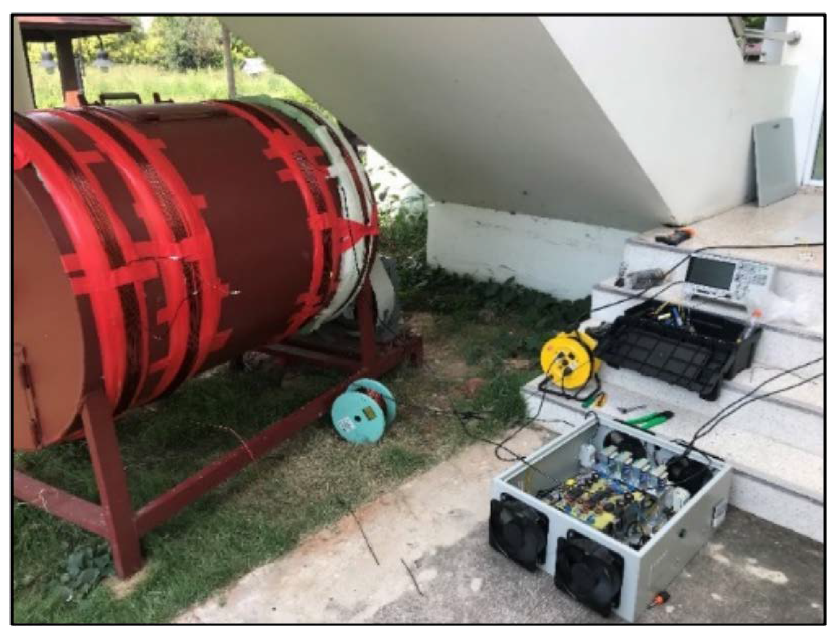
2. Materials and Methods

In this section, we discuss the design of the induction heating circuit used for drying to reduce the moisture in organic waste and eliminate germs and certain harmful microorganisms. Quality organic fertilizers can also be obtained by adding certain groups of microorganisms. The method described here is suitable for use in the production of organic fertilizers and the disposal of perishable organic waste, and thereby reduces various pollution problems. It is also environmentally friendly. This organic waste method is suitable for experimental use and real-life applications.

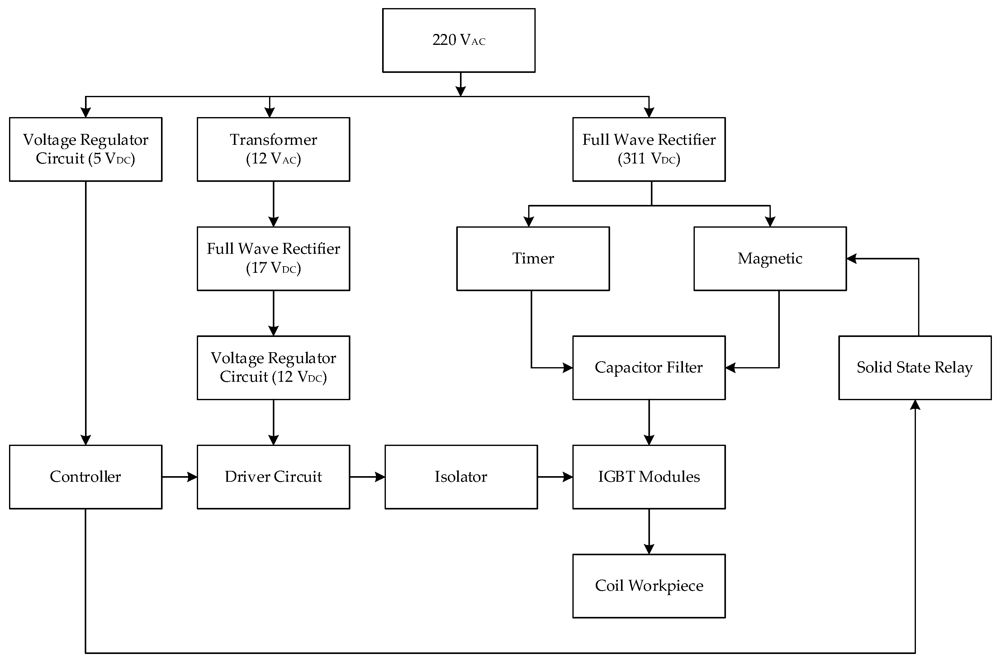
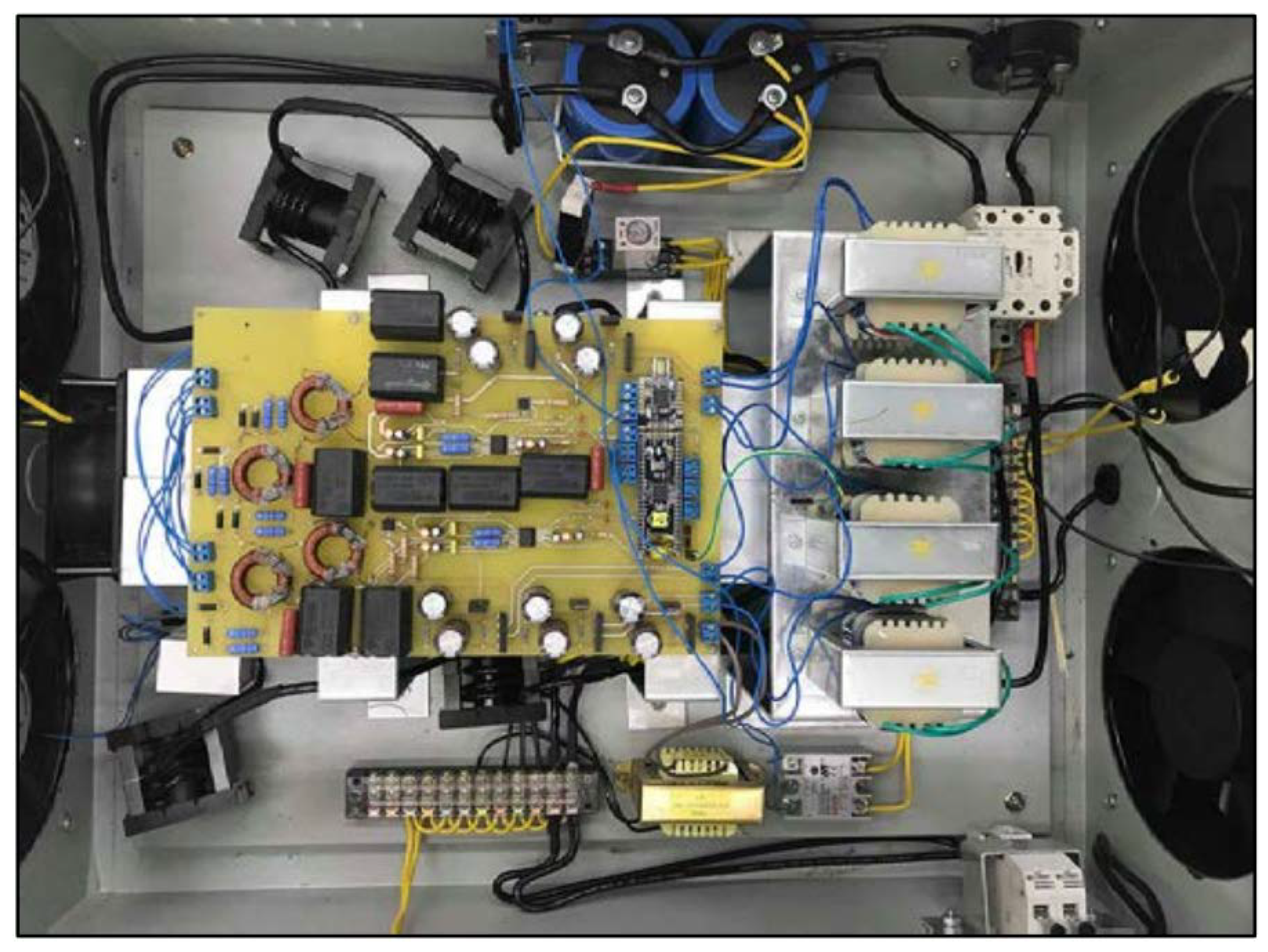
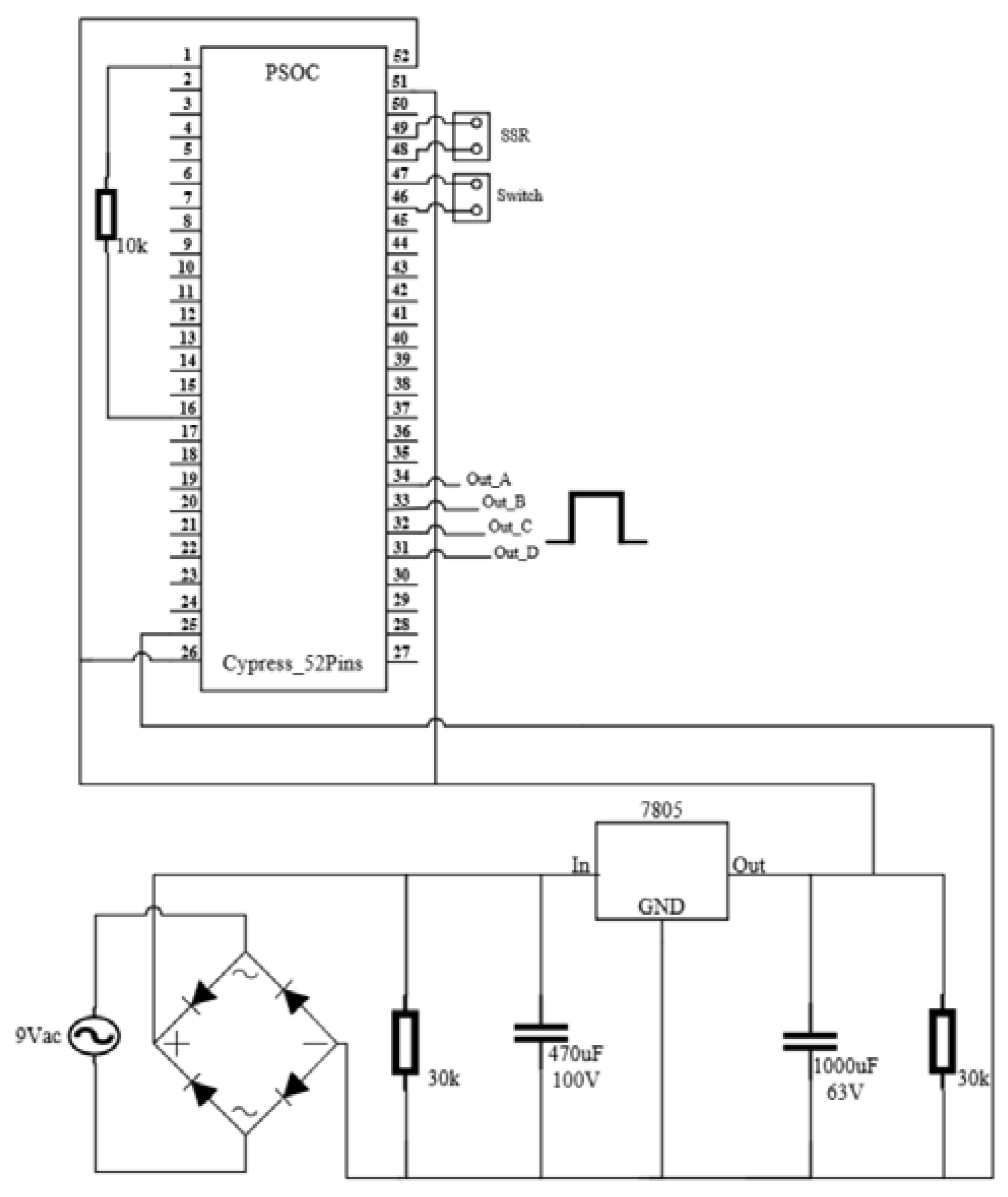
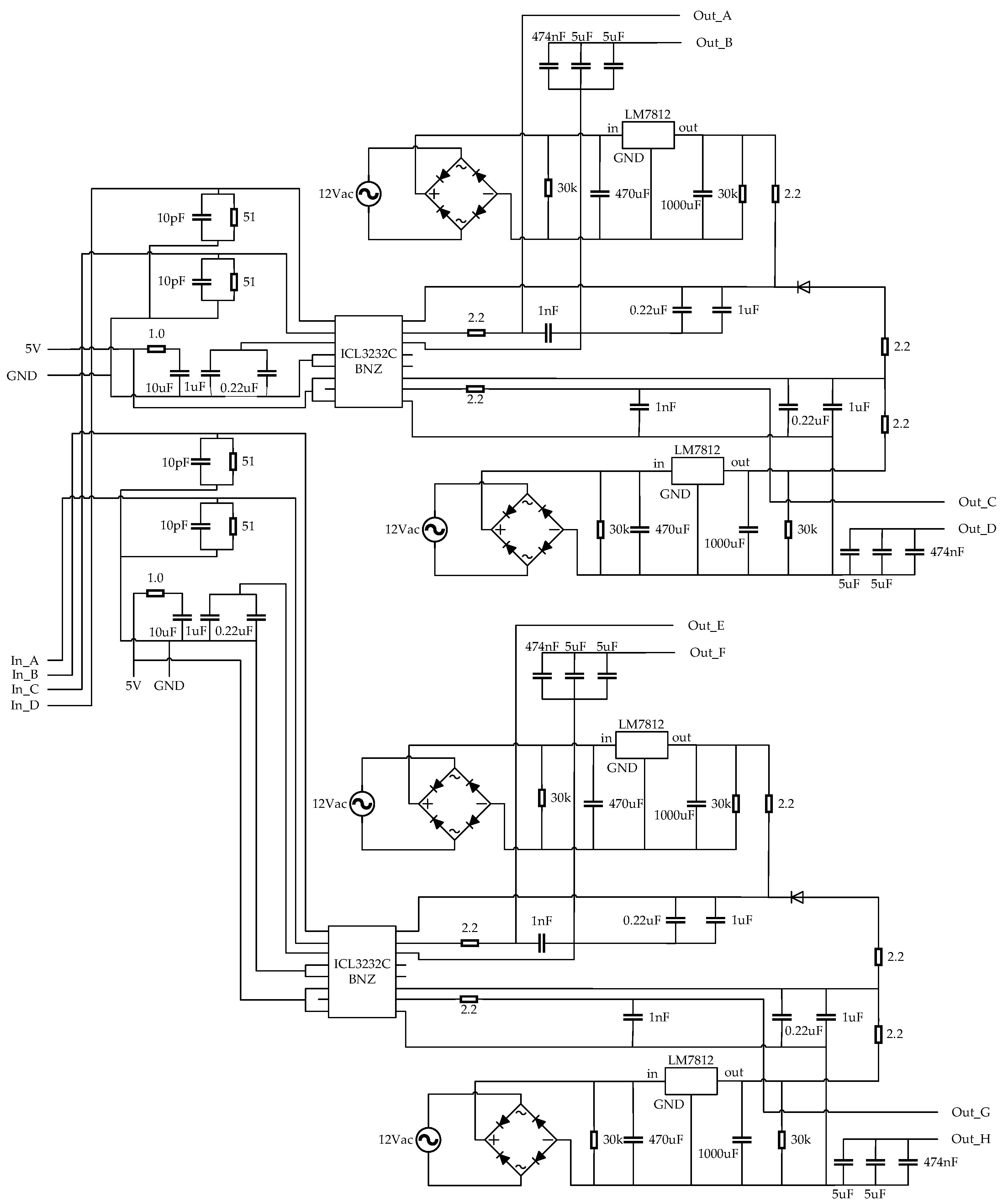
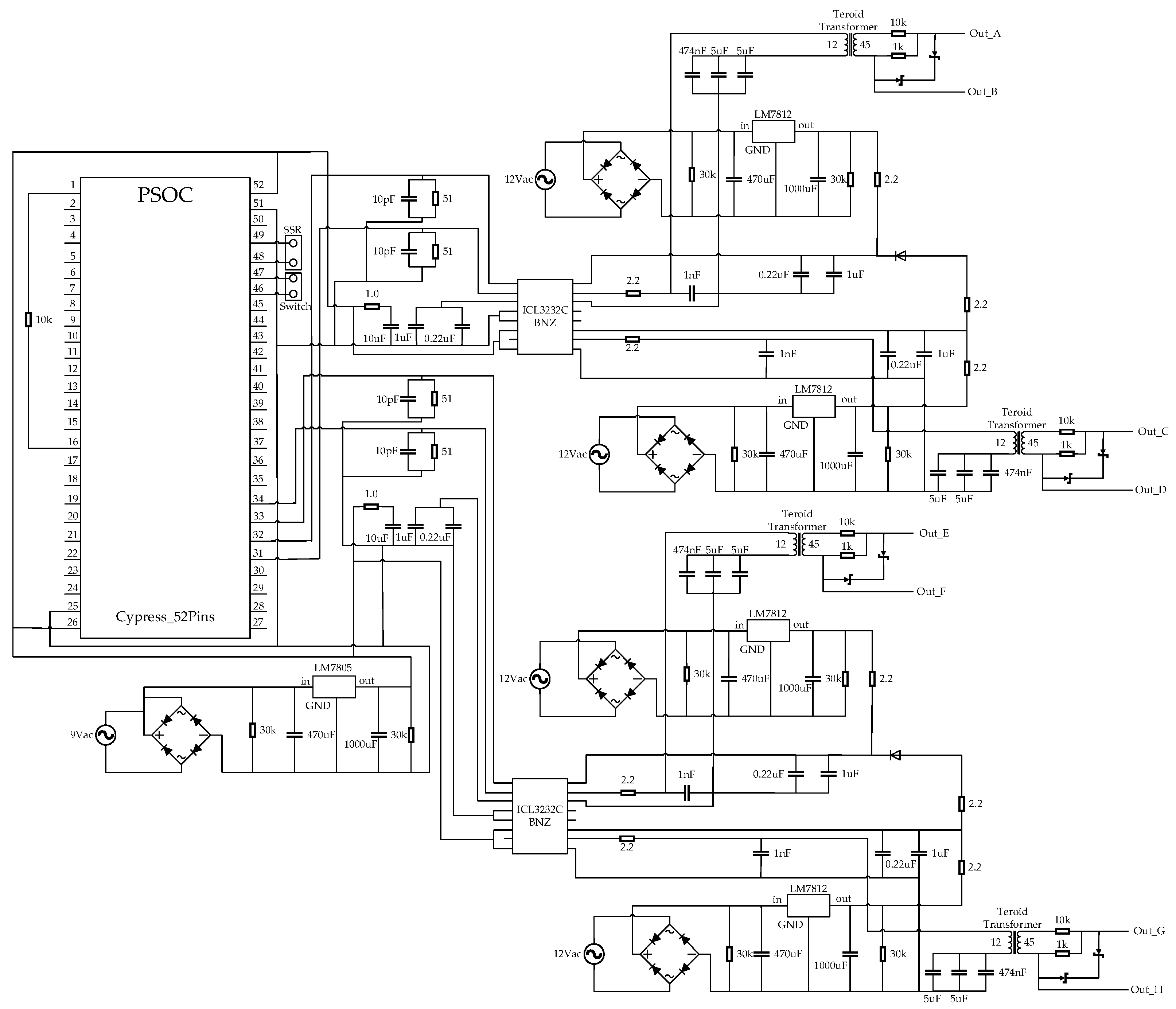
2.1. Thermal Induction Circuit Design

A diagram depicting the design of a thermal induction circuit can be found in Figure 1.
A high-frequency electric current is used during induction to generate a magnetic field and also create heat in a large oven. The working principle shown in Figure 2 represents an overview of the induction heating circuit which includes a 220 V AC power supply with a frequency of 50 Hz. This is distributed to the 3 parts of the operation as follows: the first part is fed to the rectifier circuit, which converts the AC voltage to DC power 311 VDc. Next, a large capacitor is used to smooth out the DC power supply and supply the 1200 V, 100 A IGBT, which acts as a switch to convert DC voltage to AC voltage. A high frequency of 32 A (8.88 kHz) is achieved, which drives the inductor load with a value of approximately 223.5 uH and a resistor value of 3.78 Ω, and thus heats the steel tank surface [25]. The system is driven by the IC gate driver circuit. In the second part, a 12 V power supply is used, and the controller manages the circuit frequency. The controller uses a microcontroller to control the signal of the driver circuit and uses the power supply size to control the operation of the 5 V solid-state relay.
The circuit in Figure 3 is a pulse generator circuit. We use this signal to control the on–off switch of the IGBT; this process can be divided into 3 parts. Part A is used to generate a 5 V pulse signal using a microcontroller board to generate a signal. This is also the part that controls the various systems of the circuit. Part B consists of integrated circuits (IC gate drivers) which command the IGBT to work as a complete switch without causing loss, and one device contains two built-in drivers to drive the pulse signal out to 12 V. Part C is a pulse transformer (isolated) which acts between the pulse generator circuit and is controlled with an IGBT electronic switch.
A pulse generator circuit generates a pulse waveform or a square waveform. The magnitude and frequency of the resulting waveform can be determined according to the design of the pulse waveform, which can be used to control the operation of digital circuits. The pulse signal is a repeating signal that changes from logic level 0 to logic 1 and from logic level 1 to logic level 0. This cycle repeats continuously. The signal consists of the amplitude, rising edge and falling edge, pulse width, and based line. This pulse generator circuit uses a microcontroller CY8CKTT-059 PSoC 5LP Prototyping Kit (from Cypress Semiconductor Corporation, San Jose, CA, USA) to generate a 5 V pulse signal from all 4 pins. This circuit uses power from a 5 V voltage regulator circuit, as shown in Figure 4.
The design of the gate driver circuit (gate driver) is an important part of the circuit which is responsible for linking the pulse signal generated by the microcontroller (PSoC) with the power electronic switch (IGBT). The microcontroller generates a 5 V pulse signal and sends it to the IC gate drivers UCC21520DW. The 4A/6A, 5.7 kVrms isolated dual-channel gate driver is a device with two drivers. The output is 6 A, and the input is a pulse signal. It has a 5 V power supply. This circuit receives power supply to the output side from two sets of 12 V voltage regulator circuits and produces a 12 V frequency and pulse signals for both drivers. This circuit is designed to have two sets of IC gate drivers as signal generators on both the upper and lower parts, as shown in Figure 5.
A switching power supply is applied to high-frequency power electronic equipment which is electrically isolated through a high-frequency transformer. Four transformers act as isolation circuits to isolate the grounding to each IGBT, as shown in Figure 6, to ensure convenience and safety. This also has the advantage of negative bias which prevents the interference of the IGBT drive gate and thereby prevents an explosion. In the IGBT winding of the pulse transformer A, there is a 1-to-1 transformer with a cycle number of 12:45 using ferrite cores. It then uses Zener diodes to control the voltage. The circuit operates from the 12 V pulse of the IC gate driver, which is input through the transformer, and then receives the output signal from the Zener diode. It receives +12 V and −12 V signals so that it can stop the conductive current to achieve control. The IGBTs can be turned on and off. There are two groups of IGBTs in the circuit that can share the workload and reduce losses.
When the circuits in each part are combined, a pulse generator circuit uses this signal to control the on–off switch of the high-frequency IGBT again. This circuit receives a 24 V pulse signal as +12 V input and −12 V 2 output, as shown in Figure 7.

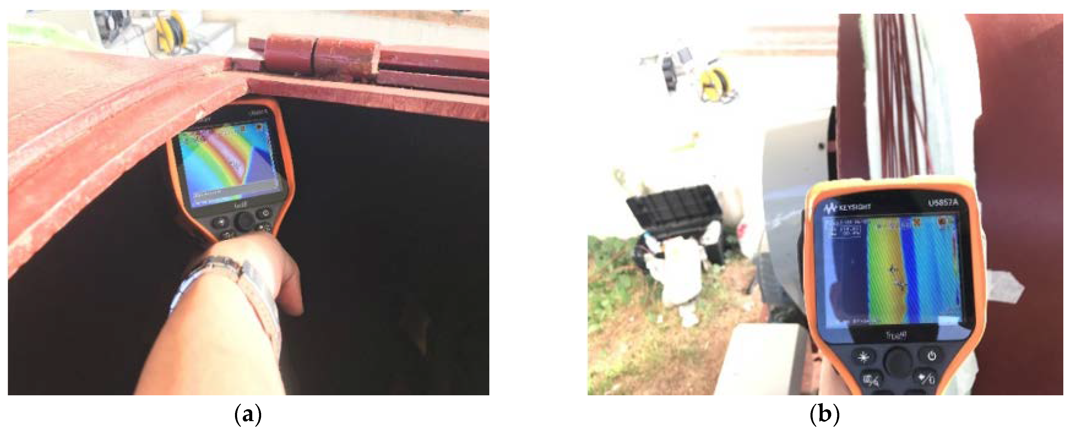
2.2. Temperature Analysis against Moisture and Thermal Energy of Organic Waste

In this research, the moisture from the organic waste was removed, reducing the humidity to 35 percent, via heating at about 85–95 °C. Then, the power, heat, and electrical energy of the system were calculated to analyze the inductor assembly. The heat was applied to the fermentation tank (the bioreactor). This designed fermentation tank can contain up to 500 kg of organic waste with an initial moisture content of about 65–75 percent, which is then reduced to 40 percent. The remaining final weight of raw materials was approximately 230 kg, as determined using Equation (1):
W f = W i ( 1 M i ) 1 M f
where Wf is the final weight (kg), Wi is the initial weight (kg), Mi is the initial humidity (percent), and Mf is the final moisture content after dehumidification (percent).
Based on this calculation, the final weight Wf = 230 kg and the evaporated water was 500–230 kg, which equals 270 kg. Then, we used the amount of evaporated water to calculate the heat energy from Equation (2):
Q T o t a l = m c Δ T + m l
where QTotal is the total heat energy (calories), m is the weight of evaporated water (g), and C is the specific heat energy of water. (1 calorie per gram of Celsius), ∆T is the temperature change from the normal temperature (Celsius), and l is the latent heat of steam conversion (540 calories per gram), which equals 1.647 × 10⁸ calories or 16.47 × 10⁷ J.
When calculating the power from the total dehumidification time (20 h), we use Equation (3):
P = Q t
The total power in 20 h is 6.863 kW. Our heating method draws heat directly from the oven. Therefore, the heat energy is transferred to the storage tank. Consequently, the heat energy in the storage tank is lost and accumulated before being transferred to the organic waste again. In addition, the thickness of the baking pot is 10 mm, and the power of each heater is about 9.6 kW. Two machines in total, with total power of 19.6 kW [26] are sufficient to dry a large amount of waste in less time. We then determined the cost of running the heater for 20 h, which was about THB 1024, corresponding to THB 3.50 per unit of electricity.
Assuming the baking drum has a diameter of 110 cm and a length of 155 cm, the volume of water in the drum can be calculated as shown in Equation (4):
V = π r 2 h
where V is the volume of the cylindrical tank (cubic centimetres), r is the diameter (centimeters), and h is the rubber of the tank (centimeters).
The volume is equal to 1,479,014 cubic centimeters, and the drum can contain ¾ of the tank’s waste. The weight without the stirrer is approximately 1.1 tons. However, when the stirrer is inside the tank, it can hold a weight of 400 kg, which is comparable to the capacity of a far larger tank. Additionally, to create a bin capable of containing about 1 ton of waste, we can increase the size by 150 cm in diameter and 250 cm in length [27]. When calculating the volume without stirring blades, it is 4,417,867 cubic centimeters. When there is a stirrer in the bin and ¾ of the bin is loaded, the volume of waste that can be stored is approximately 1,200,000 cubic centimeters or 1.2 tons.

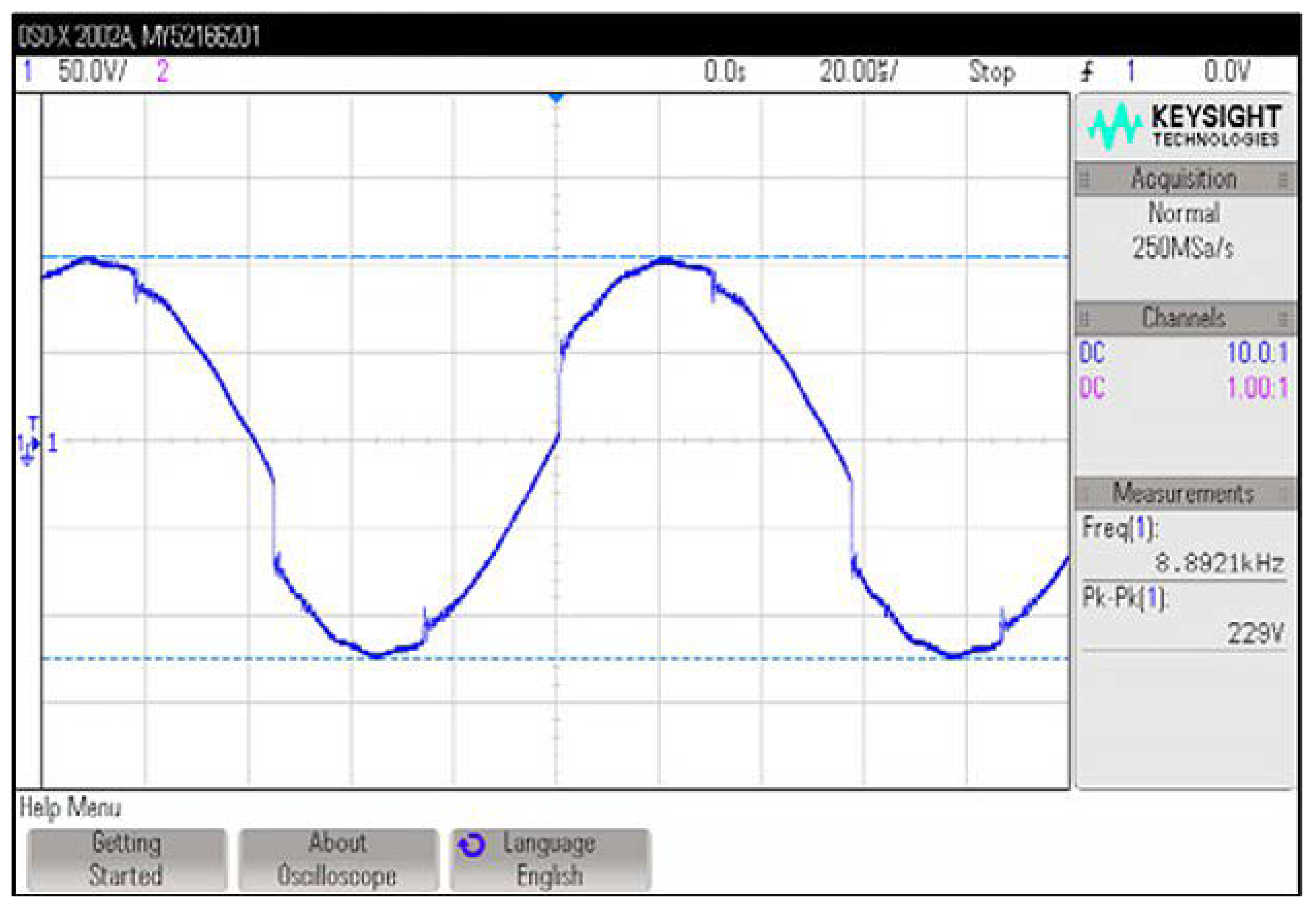
3. Results and Discussion

We constructed a large-scale induction heating machine that directly heats the tank, and used it in an experiment involving an oven. We analyzed the heat energy, temperature, and time needed to heat the oven quickly. Thus, a number of copper coil winding turns were designed. Initially, one set of copper wire was wound, and the apparatus was set as shown in Figure 8 to monitor the Joule frequency of the wound copper wire. The capacitor value used was appropriate for a maximum-efficiency heater [28,29,30].
After that, the temperature inside and outside the tank after 90 min was checked. The internal temperature of the wound coil reached as high as 150 °C, and the outside temperature near the coil was around 110 °C, as shown in Figure 9.
After checking that the copper wire wrapped around the large tank, the induction heating machine was used to heat the tank directly. We then wrapped four sets of copper wire around the area to achieve the highest efficiency in direct heating to the tank, as shown in Figure 10.
When the copper wire is wound around a total of four groups of cans, the inductor value of each coil should be as similar as possible: about 190. A mini-Henry was used for all four heaters. This machine covers the tank with heat-resistant fibers to retain heat and prevent heat from entering from the outside, as shown in Figure 11.
After the four induction heating machines were built, four sets of copper coils were applied by adjusting the Joule frequency of each machine, and the coils were configured to draw the maximum current. A large power supply of 1000 V/30 A was used to supply power to the machine to adjust the Joule frequency and determine the current required. We adjusted the voltage up to various values to check the operation and current resistance of the induction heating machine. (See Table 1 to see the frequencies used). The load current drawn by each appliance to which the heater is connected is shown in Figure 12.
We measured the signals of each heater to see if the frequency and signal image were distorted, as shown in the graph in Figure 13.
Table 1 shows the current values of all four induction heating devices when increasing the pressure according to the values in the table. The table also shows the frequency used along with the values for the inductance (uH) and resistance (Ω) used to encapsulate the tank of all four machines.
When turning on the four heaters and the wound copper coils around the tank at different times to measure the value of the current drawn by the load, the temperature of the coil and the temperature inside the tank, the values of each coil region were observed to be similar. These values are summarized in Table 2.
After heating the tank for about 45 min, the current began to stabilize. At this point, it was around 23 A, and the temperature inside the tank at the coil-specific area was about 125 °C. It took about 90 min for heat transfer inside the tank to result in a temperature of about 130 °C throughout the tank.
The researchers then designed another experiment using only two heaters since using all four machines would make transportation and installation more difficult, as well as increase the electricity use. Therefore, a heating method using four machines is not suitable at this time.
Thus, we focused on a design using two induction heating machines with four sets of copper wires to obtain sufficient heat. We ensured that this would be suitable for the size of the bioreactor by designing a new coil which removes half of all the existing coils. Then, we connected copper sets 1 and 2 and 3 and 4 in series, as shown in Figure 14. This resulted in two sets of inductance wires, each with the same inductance, so there was no need to adjust the capacitor value; it could be used with both heaters to increase the efficiency of the heat energy in the tank [31,32].
Once the design with two sets of copper wire was in place, the two heat inductors were fitted to a large baking hull, as shown in Figure 15, and we adjusted the appropriate Joule frequency for this new wire unit to allow the maximum current to be drawn.
We measured the signal and adjusted the frequencies of the two heat inductors, as shown in Figure 16, so that they could draw the maximum current which would be suitable for practical use.
Table 3 shows the current values of both induction heating devices when adjusting the pressure higher according to the table. It also shows the frequency used, along with the values for the inductor (uH) and resistor (Ω) used to encapsulate the tank of both machines.
In the experiment with both heaters, it can be seen that the value for the inductor was about 218 uH, that for the resistor was about 3.6 Ω, and the ideal frequency for pulling the maximum current was 8.892 kHz. Two machines at 320 V could achieve a total of about 34 A.
Table 4 after applying power to heat the tank for 30 min, the temperature inside the tank and around the coil reached about 100 °C; the current began at about 24 A. Once the power had been applied for about 90 min, the tank temperature reached 115 °C. This process is suitable for practical use because it does not take long to heat the tank using only two machines, and the temperature of the oven can be used to dry organic waste to accelerate decomposition.
In our research, two of the induction heaters were used to heat organic waste, which included dried leaves, grass straw, cow dung, and infected chicken carcasses weighing 175, 250, 350, and 500 kg, respectively. We heated the waste for 20 h. At the beginning of the process, the temperature of the materials was 30 °C and they had a 70% moisture level. We demonstrated that the first 8 h of heating could increase the temperature of the waste from 30 to 95°C. This was maintained up to 20 h. Finally, the temperature of the waste remained constant between 85 and 95 °C as shown in Figure 17.
To ensure the reliability of the experimental results, the experiments were repeated to analyze whether the results followed similar trends for accuracy and precision. The test involved mixing organic waste in quantities of 175, 250, 350, and 500 kg. Each quantity was tested five times to observe the temperature, moisture, and weight changes after 20 h of heating, shown in Table 5.
After conducting the test five times, we plotted the average temperature and moisture values obtained from the table, as shown in Figure 18.
After 20 h of heating, the waste’s weight reduced to 74, 115, 162, and 230 kg for each of the four materials, respectively, and 35% moisture. A four-hour cooling time was required to reduce the temperature to 40 °C before mesophilic microorganism spores were added in order to turn it into a quality organic fertilizer, as shown in Figure 19. In brief, this process of disposing of organic waste and infected waste can create quality organic fertilizer within 24 h using the heat from a powerful induction heater.
Based on the above, we can obtain energy sources for induction heating with a high efficiency of more than 80% compared with other energy sources such as biomass furnaces or gas applications. Including the use of heating coils that use the same electrical energy but using induction heat will achieve the highest efficiency in heating.
Based on the results in Table 6, it was found that induction heating is the most cost effective form of heating compared with other heating methods, due to the efficiency and the value of using this type of heat.
In these experiments, we demonstrated that 100–500 kg of organic waste can be put into the machine per cycle. The organic waste can be mixed or separated; this does not affect the heating. It always maintains a heating efficiency >80%; the heating efficiency is not affected by the amount of organic waste due to the efficiency of the induction heat generator.

4. Conclusions

At present, there are many forms of thermal energy which are very useful in the treatment of organic wastes, such as biomass burning, tungsten coil heating, solar heating, and infrared heating, which are expensive and require high power consumption. These also pollute the environment, so this study proposes a heater design. The baking pan is induced by a large magnetic field and subsequently heated. The system can be used to decompose and treat organic wastes and transform them into high-quality organic fertilizers. The efficiency of this induction heating method is 80% higher than other heating methods. It is also a clean, environmentally friendly, and cost-saving form of energy due to its direct use of electricity as energy. Therefore, compared with other forms of heating, it is the most valuable. First, we designed and manufactured a −12 V to +12 V pulse generator circuit to drive an IGBT switch with a frequency of 8.88 kHz. Next, the copper coil wound around the water tank was designed for use in the heater, as described in Experiment 2. In this study, two induction heaters were used. Each of the heaters produced 30 A and 32 A of current. Using two copper wires, the inductor reached 207.4 uH and 218.8 uH at frequencies of 8.892 kHz and 8.804 kHz, respectively, heating the whole tank to about 120 °C in about 90 min. We created an induction heater to heat a large baking pot, and it was applied to the decomposition of organic waste, dead chicken residues, fresh residues, fruit and vegetable residues, straw, oil skin, crushed sugar cane, soot and duck dung. These were put in the oven for decomposition; then, the heater and mixing system were turned on for 20 h, which gradually increased the temperature of the garbage. The moisture level of the garbage gradually dropped to 30–40%; we then waited for the material temperature to cool. At a temperature of 40 °C, we added microorganisms to aid with decomposition. Then, we transferred the mixture into fertilizer bags and waited for about 2 weeks. Shortly afterwards, high-quality organic fertilizer was obtained from the decomposition of organic waste.

Author Contributions

Conceptualization, T.T., S.S. and C.T.; methodology, T.T., K.T. and K.L.; validation, T.T., K.T. and C.T.; formal analysis, S.K.; investigation, C.T.; resources, S.K.; data curation, T.T.; writing—original draft preparation, K.T.; writing—review and editing, T.T. and K.T.; visualization, K.T. and K.L.; supervision, T.T. and C.T.; project administration, T.T. and C.T.; funding acquisition, T.T. and C.T. All authors have read and agreed to the published version of the manuscript.

Funding

This research was funded by the Suranaree University of Technology (SUT), the Thailand Science Research and Innovation (TSRI), and the National Science Research and Innovation Fund (NSRF) (NRIIS no. 179341).

Data Availability Statement

Not applicable.

Acknowledgments

This work was supported by the Suranaree University of Technology (SUT), the Thailand Science Research and Innovation (TSRI), and the National Science Research and Innovation Fund. The authors deeply appreciate the valuable comments and recommendations provided by the reviewers, which greatly improved this article.

Conflicts of Interest

The authors declare no conflict of interest.

References

  1. Chiew, Y.L.; Spångberg, J.; Baky, A.; Hansson, P.-A.; Jönsson, H. Environmental impact of recycling digested food waste as a fertilizer in agriculture—A case study. Resour. Conserv. Recycl. 2015, 95, 1–14. [Google Scholar] [CrossRef]
  2. Palmiotto, M.; Fattore, E.; Paiano, V.; Celeste, G.; Colombo, A.; Davoli, E. Influence of a municipal solid waste landfill in the surrounding environment: Toxicological risk and odor nuisance effects. Environ. Int. 2014, 68, 16–24. [Google Scholar] [CrossRef]
  3. Frederickson, J.; Butt, K.R.; Morris, R.M.; Daniel, C. Combining vermiculture with traditional green waste composting systems. Soil Biol. Biochem. 1997, 29, 725–730. [Google Scholar] [CrossRef]
  4. Jiang, Y.; Ju, M.; Li, W.; Ren, Q.; Liu, L.; Chen, Y.; Yang, Q.; Hou, Q.; Liu, Y. Rapid production of organic fertilizer by dynamic high-temperature aerobic fermentation (DHAF) of food waste. Bioresour. Technol. 2015, 197, 7–14. [Google Scholar] [CrossRef]
  5. Chen, Y.; Yu, F.; Liang, S.; Wang, Z.; Liu, Z.; Xiong, Y. Utilization of solar energy in sewage sludge composting: Fertilizer effect and application. Waste Manag. 2014, 34, 2014–2021. [Google Scholar] [CrossRef]
  6. Hou, J.; Li, M.; Xi, B.; Tan, W.; Ding, J.; Hao, Y.; Liu, D.; Liu, H. Short-duration hydrothermal fermentation of food waste: Preparation of soil conditioner for amending organic-matter-impoverished arable soils. Environ. Sci. Pollut. Res. 2017, 24, 21283–21297. [Google Scholar] [CrossRef]
  7. Matej, K.; Anze, Z.; Damijan, M.; Tomaz, J. Numerical analysis and thermographic investigation of induction heating. Int. J. Heat Mass Transf. 2010, 53, 3585–3591. [Google Scholar] [CrossRef]
  8. Lenka, J.; Andrej, G.; Peter, K.; Milan, S. Optimization of the Induction Heating Process in Order to Achieve Uniform Surface Temperature. Procedia Eng. 2016, 136, 125–131. [Google Scholar] [CrossRef] [Green Version]
  9. Wu, S.; Xu, X.; Yang, N.; Jin, Y.; Jin, Z.; Xie, Z. Non-Conventional Induction Heat Treatment: Effect of Design and Electrical Parameters on Apple Juice Safety and Quality. Foods 2022, 11, 3937. [Google Scholar] [CrossRef]
  10. Jeerasak, W.; Jirasak, S.; Wanchai, S. Innovative of induction heating. J. Humanit. Soc. Sci. Thonburi Univ. 2014, 8. Available online: https://so03.tci-thaijo.org/index.php/trujournal/article/view/56692 (accessed on 18 February 2023).
  11. Elepaño, A.R.; Satairapan, K.T.; Darmian, C.E. Chapter 472—Development of a Rice Hull Cyclonic Furnace for Drying Applications. In World Renewable Energy Congress VI; Sayigh, A.A.M., Ed.; Pergamon: Oxford, UK, 2000; pp. 2190–2193. [Google Scholar] [CrossRef]
  12. Karunanithy, C.; Shafer, K. Heat transfer characteristics and cooking efficiency of different sauce pans on various cooktops. Appl. Therm. Eng. 2016, 93, 1202–1215. [Google Scholar] [CrossRef]
  13. Energy in buildings. Available online: https://www.open.edu/openlearn/nature-environment/energy-buildings/content-section-0?active-tab=description-tab (accessed on 24 August 2015).
  14. Ye, Q.; Zeng, J.; Li, Y.; TYuan, P.; Wang, F. Heat Integration for Phenols and Ammonia Recovery Process of Coal Gasification Wastewater Considering Optimization of Process Parameters. Energies 2022, 15, 9258. [Google Scholar] [CrossRef]
  15. Tudbury, C.A. Electric and magnetic conditions inside an induction-heated workpiece. Trans. Am. Inst. Electr. Eng. Part II: Appl. Ind. 1959, 78, 79–83. [Google Scholar] [CrossRef]
  16. Watanabe, T.; Nagaya, S.; Hirano, N.; Fukuri, S. Elemental Development of Metal Melting by Electromagnetic Induction Heating Using Superconductor Coils. IEEE Trans. Appl. Supercond. 2016, 26, 1–4. [Google Scholar] [CrossRef]
  17. Han, Y.; Wen, H.; Yu, E. Study on electromagnetic heating process of heavy-duty sprockets with circular coils and profile coils. Appl. Therm. Eng. 2016, 100, 861–868. [Google Scholar] [CrossRef]
  18. Ma, J.; Zhang, L.; Mu, L.; Zhu, K.; Li, A. Thermally assisted bio-drying of food waste: Synergistic enhancement and energetic evaluation. Waste Manag. 2018, 80, 327–338. [Google Scholar] [CrossRef]
  19. Liang, C.; Das, K.C.; McClendon, R.W. The influence of temperature and moisture contents regimes on the aerobic microbial activity of a biosolids composting blend. Bioresour. Technol. 2003, 86, 131–137. [Google Scholar] [CrossRef]
  20. Sarkar, S.; Pal, S.; Chanda, S. Optimization of a Vegetable Waste Composting Process with a Significant Thermophilic Phase. Procedia Environ. Sci. 2016, 35, 435–440. [Google Scholar] [CrossRef]
  21. Kim, M.-S.; Kim, D.-H.; Yun, Y.-M. Effect of operation temperature on anaerobic digestion of food waste: Performance and microbial analysis. Fuel 2017, 209, 598–605. [Google Scholar] [CrossRef]
  22. Raut, M.P.; Prince Williams, S.P.M.; Bharttacharyya, J.K.; Chakrabarti, T.; Devotta, S. Microbial dynamics and enzyme activities during rapid composting of municipal solid waste—A compost maturity analysis perspective. Bioresour. Technol. 2008, 99, 6512–6519. [Google Scholar] [CrossRef]
  23. Nair, J.; Okamitsu, K. Microbial inoculants for small scale composting of putrescible kitchen wastes. Waste Manag. 2010, 30, 977–982. [Google Scholar] [CrossRef]
  24. Chang, J.I.; Hsu, T.-E. Effects of compositions on food waste composting. Bioresour. Technol. 2008, 99, 8068–8074. [Google Scholar] [CrossRef]
  25. Sin, S.-J.; Zahed, I. Ampere’s law and energy loss in AdS/CFT duality. Phys. Lett. B 2007, 648, 318–322. [Google Scholar] [CrossRef] [Green Version]
  26. Nian, S.-C.; Huang, M.-S.; Tsai, T.-H. Enhancement of induction heating efficiency on injection mold surface using a novel magnetic shielding method. Int. Commun. Heat Mass Transf. 2014, 50, 52–60. [Google Scholar] [CrossRef]
  27. Vonsovskii, S.V. Ferromagnetic Resonance, 1st ed.; Pergamon Press: New York, NY, USA, 1966. [Google Scholar]
  28. Nian, S.-C.; Tsai, S.-W.; Huang, M.-S.; Huang, R.-C.; Chen, C.-H. Key parameters and optimal design of a single-layered induction coil for external rapid mold surface heating. Int. Commun. Heat Mass Transf. 2014, 57, 109–117. [Google Scholar] [CrossRef]
  29. Li, Z.-F.; Hu, J.-C.; Huang, M.-S.; Lin, Y.-L.; Lin, C.-W.; Meng, Y.-M. Load Estimation for Induction Heating Cookers Based on Series RLC Natural Resonant Current. Energies 2022, 15, 1294. [Google Scholar] [CrossRef]
  30. Leelachariyakul, B.; Yutthagowith, P. Accurate Circuit Parameter Determination of a Resonant Power Frequency Converter for High-Voltage and Partial Discharge Tests. Energies 2022, 15, 5497. [Google Scholar] [CrossRef]
  31. Gwóźdź, M. The Application of Tuned Inductors in Electric Power Systems. Energies 2022, 15, 8481. [Google Scholar] [CrossRef]
  32. Cha, K.-H.; Ju, C.-T.; Kim, R.-Y. Analysis and Evaluation of WBG Power Device in High Frequency Induction Heating Application. Energies 2020, 13, 5351. [Google Scholar] [CrossRef]
Figure 1. Block diagram of the thermal induction circuit.
Energies 16 02123 g001
Figure 2. Heat induction machine system.
Energies 16 02123 g002
Figure 3. The three different frequency generator circuits of the system.
Energies 16 02123 g003
Figure 4. Pulse signal generator circuit.
Energies 16 02123 g004
Figure 5. The circuit driving the current to the electronic switching.
Energies 16 02123 g005
Figure 6. The pulse signal generator circuit.
Energies 16 02123 g006
Figure 7. Schematic of how the set circuit generates and drives pulse signals.
Energies 16 02123 g007
Figure 8. Heat induction machine applied to large bioreactor.
Energies 16 02123 g008
Figure 9. (a) The temperature inside the tank in the copper wire area. (b) The temperature outside the tank around the copper coil area.
Energies 16 02123 g009
Figure 10. All four sets of copper wire wrapped around the bioreactor.
Energies 16 02123 g010
Figure 11. Four sets of wire-wrapped heating bins ready to be used for heating and decomposing organic waste.
Energies 16 02123 g011
Figure 12. A heater with a total of 4 sets of bioreactors applied simultaneously with a set of copper wire.
Energies 16 02123 g012
Figure 13. Signals of heaters applied to the bioreactor at a frequency of 8.892 kHz.
Energies 16 02123 g013
Figure 14. The experimental set-up with all 4 sets of coils connected in 2 sets for 2 heaters.
Energies 16 02123 g014
Figure 15. Both heat inductors are used to heat the bioreactor.
Energies 16 02123 g015
Figure 16. (a) The frequency signal of the heater set 1 at a frequency of 8.892 kHz. (b) The frequency signal of the second set of heaters at a frequency of 8.804 kHz.
Energies 16 02123 g016
Figure 17. (a) The total of the waste weighted into the bioreactor. (b) After 20 h of heating, the temperature of the material was 90 °C.
Energies 16 02123 g017
Figure 18. (a) Changes in the temperature of the material with time. (b) Graph showing the relationship of moisture with time.
Energies 16 02123 g018
Figure 19. After drying, we let the material cool down and then transferred it to fertilizer bags.
Energies 16 02123 g019
Table 1. Changes in the current when the voltage of the induction heating apparatus is increased when using 4 induction heating apparatuses.
Induction HeatingInductor
(µH)
Resistor
(Ω)
Frequency
(kHz)
The Current the Load Pulls When the Voltage Value Increases (A)
30150250310320340
11603.98.5694.3614.9625.7834.8036.3839.62
21953.68.9654.4215.2025.8234.2235.4238.66
31903.48.9064.2415.3025.9834.1035.6438.66
4197.63.58.6454.2415.2626.2634.9036.3239.46
Table 2. Thermal measurements were performed using an infrared camera of the heat generated in the body over time and the current value that the load is drawn to.
Heating Time (Minutes)The Loaded Current Required (A)Coil Temperature
(°C)
Temperature Inside the Tank at the Coil Area (°C)
5323770
15276092
302565115
452368125
602275147
902275150
Table 3. Shows the change in current when the voltage of the induction heating apparatus is increased in the set up with 2 induction heating apparatuses.
Induction HeatingInductor
(µH)
Resistor
(Ω)
Frequency
(kHz)
The Current the Load Pulls When the Voltage Value Increases (A)
30150250310320340
1207.43.6728.8924.6413.1620.9233.8434.1836.52
2218.83.5498.8044.8216.2428.3835.3237.9839.52
Table 4. We measured the average heating value of each coil formed on the housing over time and checked the current consumed by the load when using the heater. The apparatus consisted of two machines and four copper wire units.
Heating Time (Minutes)The Loaded Current Pulls to Use (A)Coil Temperature
(°C)
Temperature Inside the Tank at the Coil Area (°C)
5353760
15276582
30258095
452485115
602495126
902495128
Table 5. Resulting temperature, moisture, and weight after heating for 20 h.
Starting
Weight (kg)
ParameterTest Time
12345Average
175Temperature (°C)929392919292
Moisture (%)302830323030
Weight (kg)757273767474
250Temperature (°C)898890908989
Moisture (%)323431313232
Weight (kg)116118113112114115
350Temperature (°C)909093929091
Moisture (%)343532333634
Weight (kg)163163160162164162
500Temperature (°C)888687858987
Moisture (%)333635383335
Weight (kg)227232229233227230
Table 6. Comparison of heating efficiency for different types of heating.
Types of HeatingHeating Efficiency (%)Advantages/Disadvantages
Induction heating>80Highest efficiency and uses electricity to heat, which is easy to source, and cheap.
Biomass furnaces70High efficiency, but the materials used, such as rice husks or corn husks, are rare and expensive.
Tungsten coil51.8Uses the same amount of electricity as induction heating. However, the heating efficiency is lower, and the cost of tungsten coils is relatively high.
Gas50The heating efficiency is not high, and the cost is expensive.
Coal32Easy to find but difficult to control the quantity. It also has the lowest heating efficiency.
Disclaimer/Publisher’s Note: The statements, opinions and data contained in all publications are solely those of the individual author(s) and contributor(s) and not of MDPI and/or the editor(s). MDPI and/or the editor(s) disclaim responsibility for any injury to people or property resulting from any ideas, methods, instructions or products referred to in the content.

