
FRT Capability Enhancement of Offshore Wind Farm by DC Chopper

1
Renesas Electronics America, Durham, NC 27703, USA
2
Department of Electrical and Computer Engineering, The University of Memphis, Memphis, TN 38152, USA
*
Author to whom correspondence should be addressed.
Energies 2023, 16(5), 2129; https://doi.org/10.3390/en16052129
Submission received: 24 November 2022
/
Revised: 11 February 2023
/
Accepted: 13 February 2023
/
Published: 22 February 2023
(This article belongs to the Special Issue Renewable Energy System Technologies)
Abstract
:Offshore wind farms (OWF) are establishing their position to be the next strategy to expand the growth horizon of wind power production. For proper integration of OWFs into the existing grid, the voltage source converter (VSC)-based high voltage direct current (HVDC) transmission is being vastly utilized. For the stable operation of the existing grid, these VSC-HVDC-connected OWFs need to abide by the fault ride through (FRT) grid codes. Though there are many proposed solutions to tackle the FRT problem of the onshore wind farms, all of them cannot be applied to the OWFs. The OWFs cannot respond to the onshore faults depending solely on local measurements. Additionally, there are very few techniques available for FRT capability enhancement of the doubly fed induction generator (DFIG)-based OWFs. One notable solution is the use of the DC chopper resistor across the HVDC line. No intelligent controller is yet to be reported for better control of the DC chopper resistor. To enhance the performance of the DC chopper resistor in enhancing the FRT capability of the DFIG-based OWF, a particle swarm optimization (PSO)-based nonlinear controller is proposed. Simulations carried out in the Matlab/Simulink environment reveal that the PSO-optimized nonlinear controller-based DC chopper is very effective in maintaining the FRT of the DFIG-based OWF systems. Additionally, the proposed method provides better FRT performance than that of the conventional controller-based DC chopper.
1. Introduction
Perpetual increase in electricity demand and heightened concern for carbon neutral sustainable development with environmental protection led to intense interest in the generation of electric power from the renewable energy sources. The wind energy stepped up to be one of the most prominent renewable energy sources. Its’ boom was initiated in the onshore locations and continued until recent scarcity of good wind flow locations, dispute over land ownership, difficulty to move logistics, and lower wind power utilization due to nonuniform wind speed [1]. Thus, offshore wind farms (OWF) turned out to be the next solution to facilitate the growth of wind power production with better utilization of wind power, less legal concern, and higher power production capacity by individual wind farms. In the US, the offshore wind pipeline grew 13.5% in 2022 (compared to 2021) due to falling offshore wind prices, federal action, and state-level commitments. The National Renewable Energy Laboratory estimates that the offshore wind technical potential is more than 2000 GW of capacity, which is 7200 terawatt-hours per year of generation [2].
Transmitting bulk power from the OWFs and successful and feasible integration of OWFs into the existing grid is very challenging. The voltage source converter (VSC)-based high voltage DC (HVDC) transmission is being widely adopted and the VSCs help overcome these challenges [3]. However, controlling a VSC is very challenging ensuring the system capability is subjected to variations and transients in the AC system or the grid. Special attention is needed to handle the fault conditions, as the grid codes require continuous operation of the OWF during and after the fault. Therefore, the grid codes necessitate the fault ride through (FRT) capability of the VSC-HVDC-based OWFs. Suitable FRT solutions are available for onshore wind farms [4,5,6] and many research efforts were made to address the issue.
Depending only on the local measurements, the OWFs are not able to detect and act against the onshore grid faults [7]. As a result, FRT solutions favorable for the onshore wind farms are still under active research to seek if they would be similarly effective for the OWFs. Therefore, research and investigation are required to address the OWF FRT issue. However, some solutions for the FRT capability improvement of the OWFs are available in the literature.
One strategy to improve the FRT of the OWF is to emulate a voltage sag at the offshore VSC converter intentionally to prevent active power injection into the onshore grid [8,9,10,11,12,13]. A method to employ this is to reduce the modulation index of the offshore converter to reduce the converter terminal voltage. Help from the built in FRT capability of the wind farm can also be utilized. However, coordinated control between the VSC-HVDC converter and the wind turbine converter is necessary because the wind turbine converters may tend to boost the voltage sensing a voltage sag at the VSC-HVDC converter terminal. As a voltage sag is emulated, high current flows through the converters [11] and transients are introduced into the system [8], and thus incur a disadvantage for using this scheme.
Another approach is lowering the generator torque using the offshore converter to maintain a constant frequency and reduce the active current component [12,14]. However, the slow rate of power reduction is a vital disadvantage. Offshore wind farm frequency can be perturbed to emulate the onshore frequency disturbance into the offshore wind farm, thus making the offshore wind farm respond to the onshore disturbances [15,16,17]. Perturbation of the DC link voltage is also reported [18,19] to get the desired inertial response by enhancing the control strategy. The flip side is these approaches need a high bandwidth fast communication medium for proper coordination for reliable control via these methods. Other VSC-HVDC link control strategies, such as the power synchronization control technique proposed to enhance the FRT of the OWFs [7,20]. Energy storage devices, such as superconducting magnetic energy storage (SMES) [21], and flywheel energy storage (FES) [22,23] are also proposed for FRT application. However, they are expensive and high energy storing capacity is required.
The installation of a DC chopper resistor across the HVDC line is also proposed as an OWF FRT solution. The resistor works by dissipating the extra power, causing the power imbalance during the onshore grid fault [12,24]. Insulated gate bipolar transistor (IGBT) switches or similar self-commutated devices are used to control the activation of the DC chopper resistor.
A doubly fed induction generator (DFIG)-based grid-connected OWF contains power electronic converter that is nonlinear in nature and the power system as a whole demonstrates a highly nonlinear nature. Therefore, the nonlinear controllers can capture the dynamics of the power system better than the conventional controllers. Particle swarm optimization (PSO) recently showed promising applications in power systems and renewable energy integration [25,26,27]. Based on this background, a nonlinear controller based on particle swarm optimization (PSO) is proposed for the first time to control the DC chopper resistance to enhance the FRT capability of the DFIG-based OWF. This is the novelty and originality of this paper. With the help of the proposed controller, a variable braking resistor will be offered to the fault considering the fault severity and nature. The simulations were carried out in the Matlab/Simulink software environment. A DFIG-based OWF connected to the AC grid via HVDC transmission line is used as the test system. FRT performance was investigated for symmetrical three line-to-ground (3LG) faults.
2. Materials and Methods
2.1. Description of the Power System Model
The test system used in this paper includes a DFIG scaled up to emulate a 200 MVA OWF. An individual wind turbine is scaled up to model the 200 MVA wind farm [28]. The turbine and the DFIG parameters, which are available in Table 1, are adopted from [29,30]. The rotor side converter (RSC) controller and the grid side converter (GSC) controller are given in [29,30]. The OWF is connected to the offshore sending end station (SES) through a step-up transformer. The SES converts the AC quantities into DC quantities. The SES is connected to the onshore receiving end station (RES) through a ±100 kV HVDC transmission line. A DC chopper is also connected across the two terminals of the HVDC line near the onshore RES. The RES supplies power to the onshore grid through some step-down transformer. Both the SES and RES have a two-level neutral-point clamped IGBT-based power converter. A 75 km long HVDC line does have a bipolar configuration with a 200 kV DC voltage line-to-line. The whole system is available in Figure 1. The controllers used for the SES and the RES are available in Figure 2 and Figure 3, respectively [31]. The SES converter controller is modeled to regulate the active power and reactive power of the wind farm, whereas the RES converter controller is modeled to control the DC link voltage of the HVDC line and the reactive power of the grid side [32].
2.2. PSO Controller-Based DC Chopper
2.2.1. DC Chopper
The application of a fixed resistor [24] at the HVDC transmission line is a robust way to enhance the FRT. The DC chopper resistor consumes the excess power to regulate the DC overvoltage within a safe limit. The total resistance to the DC chopper can be calculated by the equation below,
where , Vdc, and POWF are fixed resistance of the braking resistor, HVDC transmission line voltage and the OWF power, respectively. To limit the DC overvoltage at the HVDC line, the current rating of the DC chopper resistor needs to be as,
It means that the DC chopper resistor should be rated for 10% over current and 10% overvoltage at least for the transient period. To facilitate this, the DC chopper resistor used in the analysis which is given below:
2.2.2. PSO Overview
Particle swarm optimization (PSO) is a metaheuristic algorithm or global optimization algorithm [33]. It is designed to give an adequately acceptable solution to an optimization problem where the computational capacity is low and the provided information is imperfect or inadequate. It was first introduced by Eberhart and Kennedy together in 1995 [34,35]. The PSO is an optimization algorithm inspired by the natural events depending on the laws of probability. This is a variant of a direct search method. The target is to find out the optimal solution for the problem at hand given a space or range to search for the optimal solution. The PSO is very simple to implement compared to other methods. It offers an array of advantages [36,37,38,39] listed below:
- No gradient information is required;
- Simple implementation;
- The optimization time is less compared to other methods;
- Ease of use in online optimization schemes;
- Accuracy is high compared to the complexity involved;
- Objective function is used to search in the solution range or area;
- Only the numerical value of the objective function can be used;
- From the initial search point, the optimized solution is guaranteed.
2.2.3. PSO Algorithm
PSO uses the social behavior of a flock of foraging birds. The search for an optimal solution can be simulated by a group of birds looking for food in a particular two-dimensional space. The food or the optimal solution is located at a particular place and the birds have no idea about the exact food location [33,34,35]. However, the birds know their exact location at each of the searching steps. To find out the food and to get to the food location each bird checks the surrounding birds and follows the bird that is closer to the food location. Every bird is considered an individual particle and all the birds in the flock form a group or swarm. Each bird or particle records the optimal value searched by itself and the best one searched by the swarm. Each particle i (i = 1, …, n) in the swarm is defined by three vectors (xi, vi, pi); xi = (xi1, xi2, …, xin) is certain position of the particle, vi = (vi1, vi2, …, vin) is particle velocity, and pi = (pi1, pi2, …, pin) is the best particle position. Each particle records its best position or personal best Pbest,i and looks for the best position among the swarm, the global best Gbest,i. At a certain iteration step k, each particle I moves around and updates its velocity to vi(k + 1) depending on the personal best Pbest,i(k), global best Gbest,i(k), and current velocity vi(k), using the below equation:
vi(k + 1) = Ω ∗ vi(k) + c1 ∗ rand1i(k) ∗ (Pbest,i(k) − xi(k)) + c2 ∗ rand2i(k) ∗ (Gbest,i(k) − xi(k))
xi(k + 1) = xi(k) + vi(k + 1).
Here c1 and c2 are accelerating factors, and rand1i(k) and rand2i(k) are uniformly (0,1) distributed random vectors of length n, which is the inertia weight. This concept is represented in Figure 4 [40]. The global best Gbest,i, and the personal best Pbest,i determine the velocity change v(del). Present velocity v(k) and the velocity change v(del) define the new velocity for the next iteration step (k + 1). The new position is updated using Equation (4). The working principle flowchart of the PSO is available in Figure 5.
2.2.4. PSO for DC Chopper Optimization
The application of a braking resistor at the DC link of the HVDC transmission line is a proven solution and is used by many researchers. They were mostly designed to tackle the most severe three-line-to-ground (3LG) faults. In those design approaches, the full value of the braking resistance was offered in case of any kind of fault. Neither the fault type nor the depth of voltage sag at the grid is taken into consideration in this sort of approach. To resolve this problem, a nonlinear control-based variable braking resistor is proposed that would dynamically insert a variable resistor considering the voltage type and voltage dip severity. A nonlinear control is designed to generate a duty cycle d depending on the fault nature and voltage sag depth at the AC side.
The duty cycle d is the ratio of time the IGBT switches conduct (TON) to the time period of a cycle (TC = 1/fc). That is,
Here fc is the carrier frequency of the PWM generator. The variable resistance RDCR then becomes a function of duty cycle as
The variable resistance RDCR.eff will only consume the power that is produced more than the demand and provide appropriate FRT. The duty cycle d is generated using the nonlinear equation given below:
The voltage deviation is the deviation of DC voltage VdcHVDC. It is noteworthy here that, other nonlinear functions, such as the quadratic, cubic, biquadratic, logarithmic, or exponential, were also tried, but those failed to yield better performance. Some other complex nonlinear controllers may also be able to produce the desired result. However, as the nonlinear equation is simple to implement and easy to understand, and another nonlinear approach (PSO) is used to optimize it, this was used in this work. The nonlinear controller shown in Figure 6 is used to control the DC chopper resistor. During normal operation, VdcHVDC < Vth, the DC chopper IGBTs remain open. So, no current flows through them and they do not affect normal operation. At fault, VdcHVDC increases, and as it becomes greater than Vth (that is, VdcHVDC > Vth), IGBTs take a switching signal from the PWM block. The duty cycle d of the PWM is nonlinear in Equation (8). Instead of using the trial and error method to find out the optimal value of the parameter k in (8), PSO is used to search for the optimum value of k based on the minimization of the objective function. The search range was from 0 to 1000. The objective function was to minimize integral absolute error (IAE) minimization of HVDC DC voltage; that is,
It was found that for k = 640.56, the best result was obtained. The convergence of the objective function J up to the 5th iteration is depicted in Figure 7.
2.2.5. Conventionally Controlled DC Chopper
Operation and control of the DC chopper are very simple. DC voltage at the RES side of the HVDC line (VdcHVDC) is measured. It is then compared to a threshold voltage (Vth), which is considered 1.1 pu in this case. During the steady state operation, VdcHVDC < Vth and IGBT switches of the DC chopper resistor remain open. When the fault occurs, VdcHVDC tends to rise. As soon as the VdcHVDC crosses Vth, that is, VdcHVDC > Vth, IGBT switches close and consumes power to keep VdcHVDC within the limit. The hysteresis controller used for the DC chopper is shown in Figure 8.
3. Results and Discussion
To exhibit the effectiveness of the proposed PSO-optimized DC chopper and to pursue a performance evaluation among the proposed PSO-optimized DC chopper, the conventionally controlled DC chopper, and the no auxiliary controller, extensive simulations were performed. The simulation results are presented and discussed in the following subsections.
3.1. Simulation Considerations
Different scenarios are considered, and a few assumptions are made while executing the simulations. The wind speed is assumed constant at 15 m/s, as the duration of the fault is too short for the wind speed to make any substantial impact on the transient performance. Additionally, at this speed, the wind turbines produce the rated power. The system was operating normally when temporary 120 ms or six-cycle 3LG fault was applied to the onshore grid in Figure 1 at 0.1 s and withdrawn at 0.22 s. The simulation time step used for the study is 14.81 µs. To capture all of the possible details and better representation, a common period of 0 s to 10 s and per unit (pu) measurement are used in the plots. Three different scenarios are considered in the simulations; they are as follows:
- (1)
- Scenario A: with no controller;
- (2)
- Scenario B: with conventional DC chopper;
- (3)
- Scenario C: with PSO DC chopper.
3.2. FRT Performance for Onshore Grid 3LG Fault
Figure 9 shows the OWF terminal voltage profile when a temporary symmetrical or 3LG fault is applied. For the no controller case, the OWF terminal voltage goes very high right after the fault initiation and continues to rise till the fault is withdrawn.
The conventional DC chopper helps reduce the sudden voltage rise. From the zoomed view it is apparent that there is some voltage rise at the fault initiation with the conventional DC chopper. However, the zoomed view also shows that the PSO DC chopper keeps the voltage rise level to the minimum. It is quite noticeable that the PSO DC chopper outperforms the conventional control-based DC chopper and gives better FRT performance.
Figure 10 shows the OWF output active power response for 3LG fault. It demonstrates that without any controller, the output power fluctuates due to an imbalance between electrical and mechanical power. The zoomed view shows that with the conventional DC chopper, there is a jump in power after fault initiation and considerable fluctuation afterward. The PSO DC chopper limits the fluctuation and gives the steadiest output active power response and performs even better than the conventional DC chopper.
The DC link voltage response of the DFIG is presented in Figure 11. With no controller, the voltage goes very high, which may destroy the DC link capacitor. Conventional and PSO-controlled DC choppers both can prevent the rise in DC link voltage. However, the zoomed view reveals that the PSO-controlled DC chopper is prominently apt in regulating this voltage to a safe level.
The DFIG speed response for the 3LG fault is shown in Figure 12. The fault makes the DFIG speed go over and below the nominal speed, and it may cause instability if the fault duration is long enough and proper auxiliary measure is not taken. The PSO DC chopper prevents the high rate of machine speed change and ensures better stability. It is more competent to do this than the conventional DC chopper because it gives lower oscillation and faster stabilization. Additionally, it is noticeable from the zoomed portion that, right after fault initiation, the machine speed drops and then rises sharply. This bidirectional speed variation is threatening to the turbine electro-mechanical system. This harmful deviation is kept to a minimum level by the application of the PSO DC chopper.
Figure 13 and Figure 14 show the HVDC line DC voltage response at the SES and RES, respectively. It is possible to maintain the most constant HVDC line DC voltage with the PSO DC chopper as compared to that of the conventional DC chopper. This saves the HVDC line from overvoltage and possible breakdown of insulation, which are likely to occur if no controller is used.
The onshore grid voltage is presented in Figure 15. It is clear that the voltage response is the same for each case. The DC chopper does not contribute to maintaining onshore grid voltage but prevents the OWF farms from the fault, which is the primary intention of employing them.
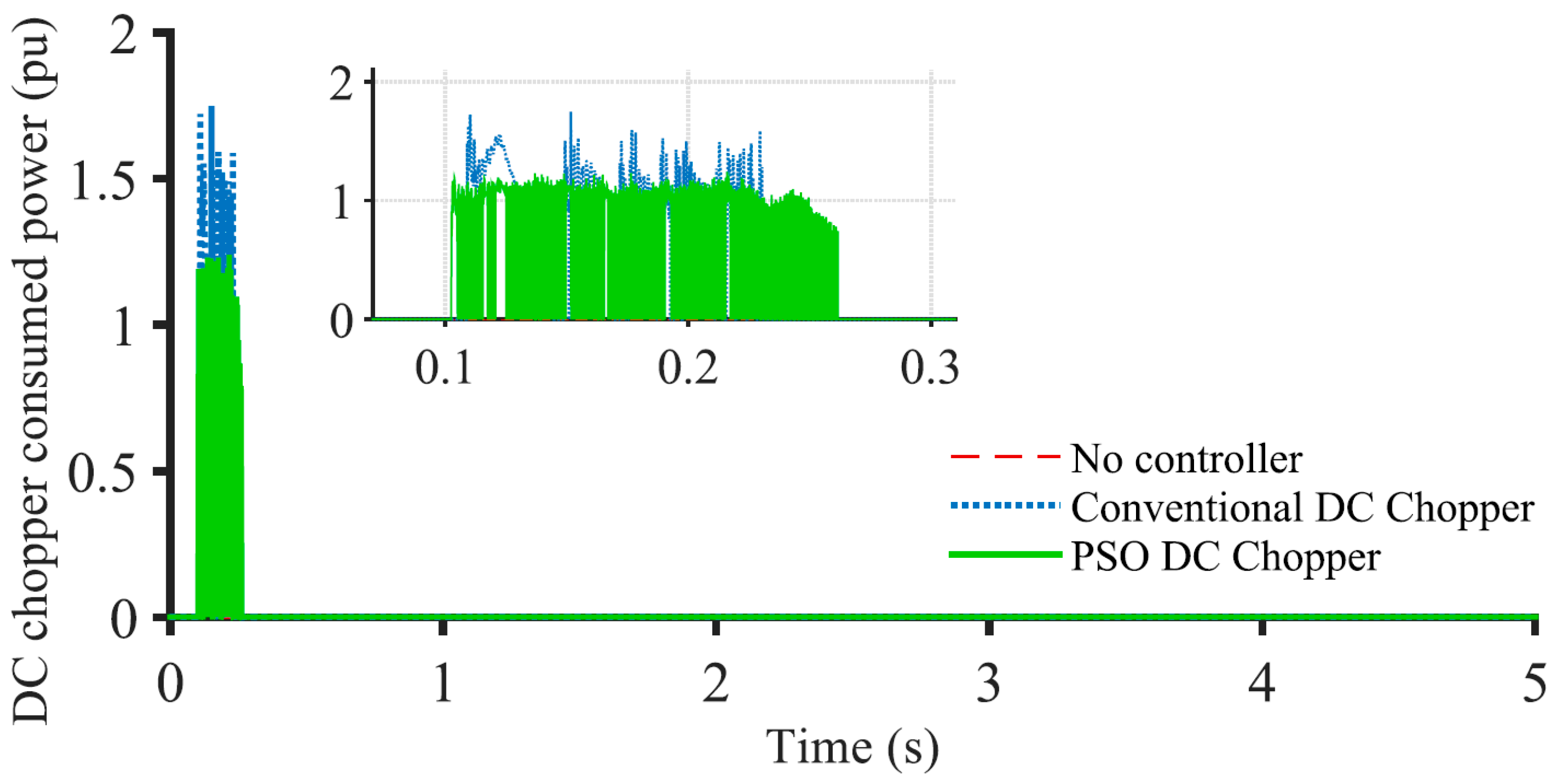
Power dissipation by the DC choppers with both the PSO-optimized controller and conventional controller are available in Figure 16. It is clear that the power consumed by the conventional DC chopper is abrupt and sudden, while the PSO one smoothly consumes power. This happens because PSO-optimized DC chopper adjusts the amount of power needed to be consumed for the best system performance. Another thing to notice here is that neither of them consumes any active power during normal operation. Hence, they have no impact on normal operation.
3.3. Index-Based Comparison
For a clear insight into the performance comparison, several integral absolute error (IAE)-based performance indices, namely, VOWF (pu·s), ωDFIG (pu·s), POWF (pu·s), and VdcHVDC (pu·s) are considered. A lower value of the indices indicates better system performance. Their definitions are given in terms of the following equations:
where ΔVOWF, ΔωDF IG, ΔPOW F, and ΔVdcHVDC represent the offshore wind farm terminal voltage deviation, the DFIG speed deviation, the active power deviation of the offshore wind farm, and the DClink voltage of the HVDC line, respectively. T refers to the time duration of interest stretching from 0.1 s to 5 s. The values of the indices for the 3LG fault at the onshore grid are presented in Table 2. The system performance is the worst without any auxiliary controller. A significant improvement is observed using the PSO DC chopper. Compared to the conventional DC chopper, the PSO-optimized DC chopper gives a lower value of the indices and hence performs better in FRT enhancement of the DFIG-based offshore wind farm.
3.4. Limitations
Since the PSO-based technique is nonlinear, it will take some computational resources to calculate and optimize for better performance. A hardware implementation of this novel solution would provide further validation of the proposed concept.
4. Conclusions
A particle swarm optimization-based DC chopper is proposed in this paper to improve the FRT capability of a DFIG-based offshore wind farm connected to an onshore power system via VSC-HVDC. A nonlinear PSO-based controller was designed and verified to control the DC chopper. The performance of the PSO-optimized DC chopper is compared with that of the conventionally controlled DC chopper. From the simulation results and discussions, it was shown that:
- (i)
- The FRT capability of a DFIG-based offshore wind farms can be enhanced noticeably using the proposed PSO-optimized DC chopper for onshore grid faults;
- (ii)
- The wind farm can continue more stable operation with the proposed PSO-optimized DC chopper;
- (iii)
- The PSO-optimized DC chopper exhibits much better performance than the conventional DC chopper;
- (iv)
- The voltage, speed, and active power profile of the system is improved from 25% to 35% at fault by using the PSO-based DC chopper over the conventionally controlled DC chopper.
The effectiveness of the PSO-optimized controller for a more complex power network and smart grid environment will be investigated in future work.
Author Contributions
Conceptualization, G.R.; methodology, G.R.; software, G.R.; validation, G.R. and M.H.A.; formal analysis, G.R.; investigation, G.R. and M.H.A.; resources, M.H.A.; data curation, G.R.; writing—original draft, G.R.; writing—review and editing, M.H.A.; visualization, G.R.; supervision, M.H.A.; project administration, M.H.A.; funding acquisition, M.H.A. All authors have read and agreed to the published version of the manuscript.
Funding
This research received no external funding.
Data Availability Statement
Not applicable.
Acknowledgments
The authors are pleased to acknowledge the financial support through Herff Fellowship from the Herff College of Engineering at the University of Memphis, USA, to complete this work.
Conflicts of Interest
The authors declare no conflict of interest.
References
- Deveci, K.; Barutçu, B.; Alpman, E.; Taşcıkaraoğlu, A.; Erdinç, O. On the importance of wind turbine wake boundary to wind energy and environmental impact. Energy Convers. Manag. 2023, 277, 116664. [Google Scholar] [CrossRef]
- US Office of Energy Efficiency & Renewable Energy: Offshore Wind Market Report. Available online: https://www.energy.gov/eere/wind/articles/offshore-wind-market-report-2022-edition (accessed on 5 February 2023).
- Changizian, M.; Mizani, A.; Shoulaie, A. Proposed a new voltage rebalancing method for pole-to-ground fault in bipolar two-level VSC-HVDC. IEEE Trans. Ind. Electron. 2022, 69, 2157–2165. [Google Scholar] [CrossRef]
- Rashid, G.; Ali, M.H. Nonlinear control-based modified BFCL for LVRT capacity enhancement of DFIG based wind farm. IEEE Trans. Energy Convers. 2017, 32, 284–295. [Google Scholar] [CrossRef]
- Rashid, G.; Ali, M.H. Fault ride through capability improvement of DFIG based wind farm by fuzzy logic controlled parallel resonance fault current limiter. J. Electr. Power Syst. Res. 2017, 146, 1–8. [Google Scholar] [CrossRef]
- Rashid, G.; Ali, M.H. Transient stability enhancement of doubly fed induction machine-based wind generator by bridge-type fault current limiter. IEEE Trans. Energy Convers. 2015, 30, 939–947. [Google Scholar] [CrossRef]
- Nanou, S.I.; Papathanassiou, S.A. Grid Code Compatibility of VSC-HVDC connected offshore wind turbines employing power synchronization control. IEEE Trans. Power Syst. 2016, 31, 5042–5050. [Google Scholar] [CrossRef]
- Erlich, I.; Feltes, C.; Shewarega, F. Enhanced voltage drop control by VSC–HVDC systems for improving wind farm fault ride through capability. IEEE Trans. Power Deliv. 2014, 29, 378–385. [Google Scholar] [CrossRef]
- Ali, S.W.; Sadiq, M.; Terriche, Y.; Naqvi, S.A.R.; Mutarraf, M.U.; Hassan, M.A.; Guerrero, J.M. Offshore wind farm-grid integration: A review on infrastructure, challenges, and grid solutions. IEEE Access 2021, 9, 102811–102827. [Google Scholar] [CrossRef]
- Farrar, N.; Ali, M.H.; Dasgupta, D. Artificial intelligence and machine learning in grid connected wind turbine control systems: A comprehensive review. Energies 2023, 16, 1530. [Google Scholar] [CrossRef]
- Ramtharan, G.; Arulampalam, A.; Ekanayake, J.B.; Hughes, F.; Jenkins, N. Fault ride through of fully rated converter wind turbines with AC and DC transmission. IET Renew. Power Gener. 2009, 3, 426–438. [Google Scholar] [CrossRef]
- Harnefors, L.; Jiang-Hafner, Y.; Hyttinen, M.; Jonsson, T. Ride-through methods for wind farms connected to the grid via a VSC- HVDC transmission. In Proceedings of the Nordic Wind Power Conference, Roskilde, Denmark, 1–2 November 2007. [Google Scholar]
- Mohammadi, L.; Avendano-Mora, M.; Barnes, M.; Chan, J. A study on Fault Ride-Through of VSC-connected offshore wind farms. In Proceedings of the IEEE Power and Energy Society, Vancouver, BC, Canada, 21–25 July 2013; pp. 1–5. [Google Scholar]
- Xu, L.; Yao, L. DC voltage control and power dispatch of a multi-terminal HVDC system for integrating large offshore wind farms. IET Renew. Power Gener. 2011, 5, 223–233. [Google Scholar] [CrossRef]
- Liu, H.; Chen, Z. Contribution of VSC-HVDC to frequency regulation of power systems with offshore wind generation. IEEE Trans. Energy Convers. 2015, 30, 918–926. [Google Scholar] [CrossRef]
- Martinez Sanz, I.; Chaudhuri, B.; Strbac, G. Inertial response from offshore wind farms connected through DC grids. IEEE Trans. Power Syst. 2015, 30, 1518–1527. [Google Scholar] [CrossRef] [Green Version]
- Silva, B.; Moreira, C.; Seca, L.; Phulpin, Y.; Lopes, J. Provision of inertial and primary frequency control services using offshore multiterminal HVDC networks. IEEE Trans. Sustain. Energy 2012, 3, 800–808. [Google Scholar] [CrossRef]
- Zhu, J.; Booth, C.D.; Adam, G.P.; Roscoe, A.J.; Bright, C.G. Inertia emulation control strategy for VSC-HVDC transmission systems. IEEE Trans. Power Syst. 2013, 28, 1277–1287. [Google Scholar] [CrossRef] [Green Version]
- Junyent-Ferré, A.; Pipelzadeh, Y.; Green, T.C. Blending HVDC-link energy storage and offshore wind turbine inertia for fast frequency response. IEEE Trans. Sustain. Energy 2015, 6, 1059–1066. [Google Scholar] [CrossRef] [Green Version]
- Mitra, P.; Zhang, L.; Harnefors, L. Offshore wind integration to a weak grid by VSC-HVDC links using power-synchronization control: A case study. IEEE Trans. Power Deliv. 2014, 29, 453–461. [Google Scholar] [CrossRef]
- Nam, T.; Shim, J.W.; Hur, K. The beneficial role of SMES coil in DC lines as an energy buffer for integrating large scale wind power. IEEE Trans. Appl. Supercond. 2012, 22, 5701404. [Google Scholar] [CrossRef]
- Daoud, M.I.; Massoud, A.M.; Abdel-Khalik, A.S.; Elserougi, A.; Ahmed, S. A flywheel energy storage system for fault ride through support of grid-connected VSC HVDC-based offshore wind farms. IEEE Trans. Power Syst. 2016, 31, 1671–1680. [Google Scholar] [CrossRef]
- Ahmed, K.; Abdel-Khalik, A.; Elserougi, A.; Massoud, A.; Ahmed, S. Fault ride-through capability enhancement based on flywheel energy storage system for wind farms connected via VSC high voltage DC transmission. In Proceedings of the 10th IET International Conference on AC and DC Power Transmission (ACDC 2012), Birmingham, UK, 4–5 December 2012; pp. 1–6. [Google Scholar]
- Chaudhary, S.K.; Teodorescu, R.; Rodriguez, P.; Kjar, P. Chopper controlled resistors in VSC HVDC transmission for WPP with full-scale converters. In Proceedings of the IEEE PES/IAS Conference on Sustainable Alternative Energy (SAE), Valencia, Spain, 28–30 September 2009; pp. 1–8. [Google Scholar]
- Muisyo, I.; Muriithi, C.; Kamau, S. Enhancing low voltage ride through capability of grid connected DFIG based WECS using WCA-PSO tuned STATCOM controller. Heliyon 2022, 30, e09999. [Google Scholar] [CrossRef]
- Kumeshan, R.; Saha, A.K. A review of swarm-based metaheuristic optimization techniques and their application to doubly fed induction generator. Heliyon 2022, 8, e10956. [Google Scholar]
- Zhu, K.; Chen, Z.; Zong, L.; Metwally, A.S.; Ali, S.; Mohammed, A.H.; Jaszczur, M. Implementation of modified multi-objective particle swarm optimization to multi-machine power system stability. J. Clean. Prod. 2022, 10, 132664. [Google Scholar] [CrossRef]
- Mohammadpour, H.A.; Santi, E. Modeling and control of gate-controlled series capacitor interfaced with a DFIG-based wind farm. IEEE Trans. Ind. Electr. 2015, 62, 1022–1033. [Google Scholar] [CrossRef]
- Rashid, G.; Ali, M.H. Application of parallel resonance fault current limiter for fault ride through capability augmentation of DFIG based wind farm. In Proceedings of the IEEE PES Transmission & Distribution (T&D) Conference & Exposition, Dallas, TX, USA, 3–5 May 2016; pp. 1–5, paper ID:TD0149. [Google Scholar]
- Rashid, G.; Ali, M.H. Asymmetrical fault ride through capacity augmentation of DFIG based wind farms by parallel resonance fault current limiter. In Proceedings of the IEEE Power Energy Society, Boston, MA, USA, 17–21 July 2016; pp. 1–5, paper ID:16PESGM0946. [Google Scholar]
- Lindberg, A. PWM and Control of Two and Three Level High Power Voltage Source Converters. Ph.D. Thesis, Royal Institute of Technology, Stockholm, Sweden, 1995. [Google Scholar]
- Matlab, VSC-Based HVDC Link. Available online: http://www.mathworks.com/help/physmod/sps/powersys/ug/vsc-based-hvdc-link.html#bqsqow_ (accessed on 5 February 2023).
- Bianchi, L.; Dorigo, M.; Gambardella, L.M.; Gutjahr, W.J. A survey on metaheuristics for stochastic combinatorial optimization. Nat. Comput. 2009, 8, 239–287. [Google Scholar] [CrossRef] [Green Version]
- Kennedy, J.; Eberhart, R. Particle swarm optimization. In Proceedings of the IEEE International Conference on Neural Networks, Perth, Western Australia, 27 November–1 December 1995; Volume 4, pp. 1942–1948. [Google Scholar]
- Eberhart, R.C.; Kennedy, J. A new optimizer using particle swarm theory. In Proceedings of the Sixth International Symposium on Micro Machine and Human Science, New York, NY, USA, 4–6 October 1995; Volume 1, pp. 39–43. [Google Scholar]
- Chen, P.-H.; Kuo, C.-C.; Chen, F.-H.; Chen, C.-C. Refined binary particle swarm optimization and application in power system. WSEAS Trans. Syst. 2009, 8, 169–178. [Google Scholar]
- Engelbrecht, A.P. Fundamentals of Computational Swarm Intelligence; John Wiley & Sons: Hoboken, NJ, USA, 2006. [Google Scholar]
- Kennedy, J.R.; Eberhart, R.C.; Shi, Y. Swarm Intelligence; Morgan Kaufmann Publishers: San Francisco, CA, USA, 2001. [Google Scholar]
- Dorigo, M.; Thomas, S. Ant Colony Optimization; The MIT Press: Cambridge, MA, USA, 2004. [Google Scholar]
- Kim, J.-Y.; Kim, H.-M.; Kim, S.-K.; Jeon, J.-H.; Choi, H.-K. Designing an energy storage system fuzzy PID controller for microgrid islanded operation. Energies 2011, 4, 1443–1460. [Google Scholar] [CrossRef] [Green Version]
Figure 1.
VSC-HVDC connected DFIG-based offshore wind farm.
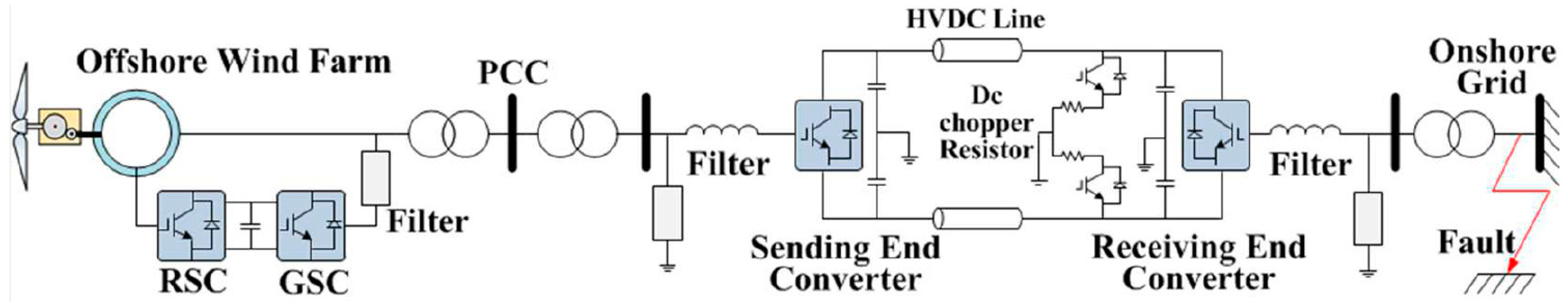
Figure 2.
SES converter controller.
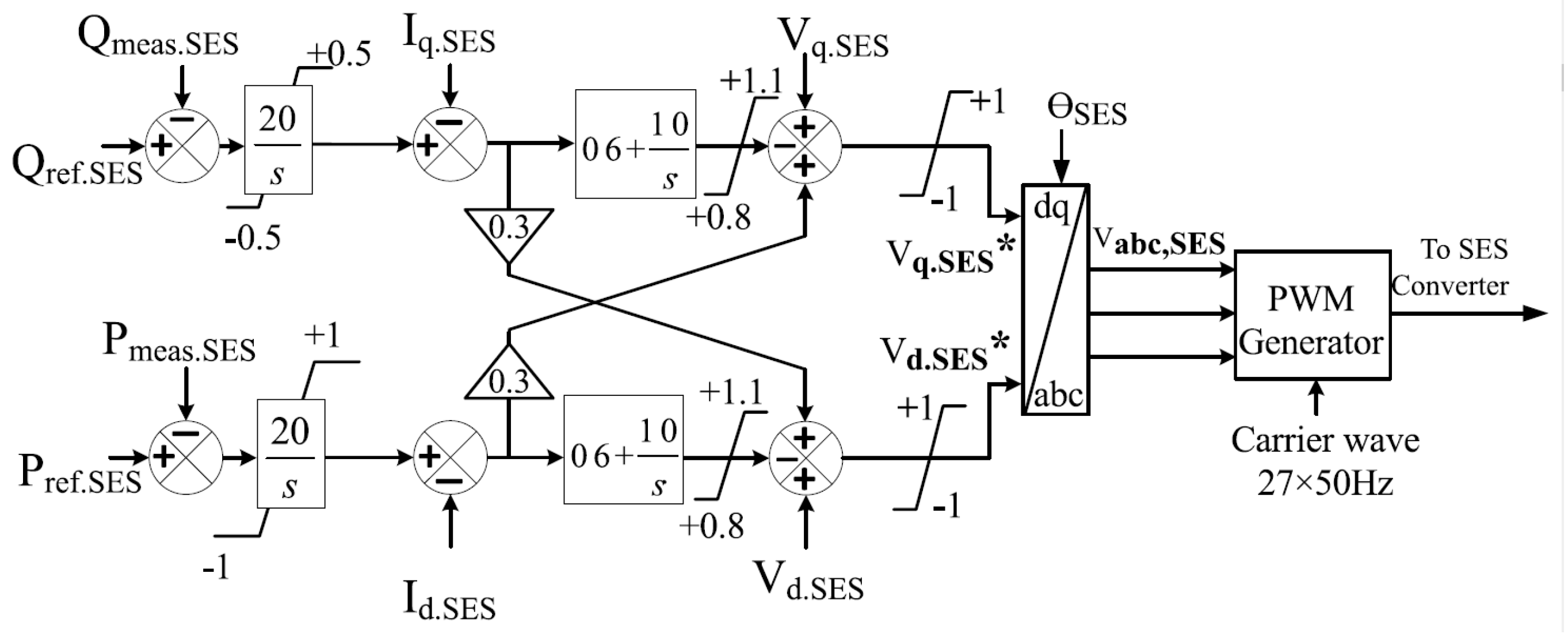
Figure 3.
RES converter controller.
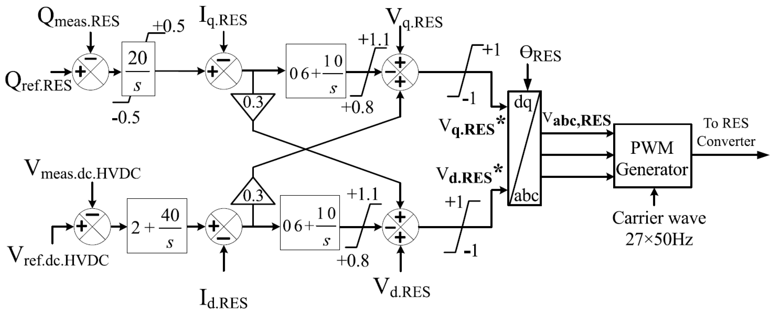
Figure 4.
Position and velocity update of each particle.
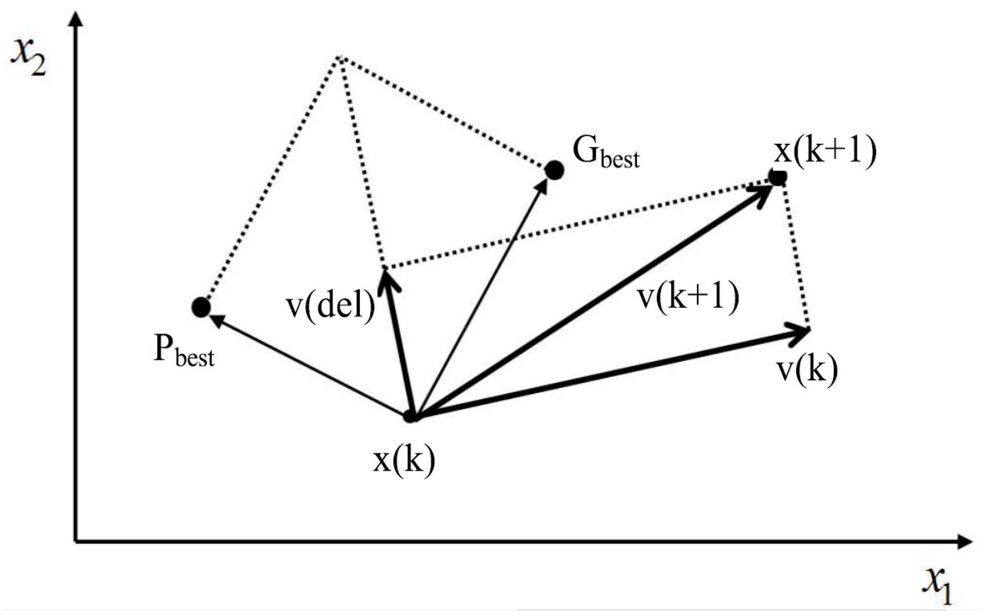
Figure 5.
Particle swarm algorithm.
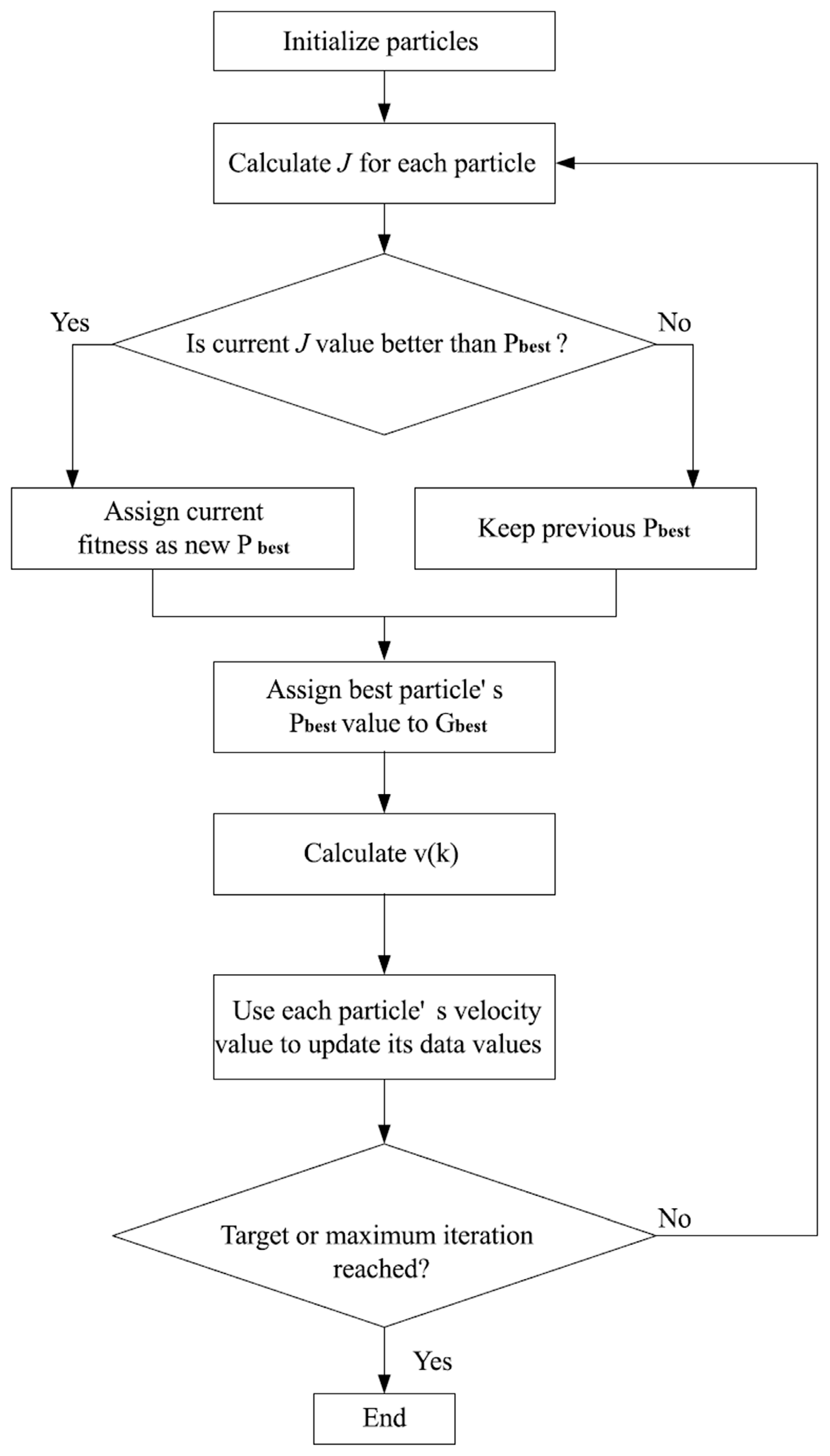
Figure 6.
PSO-optimized DC chopper controller.
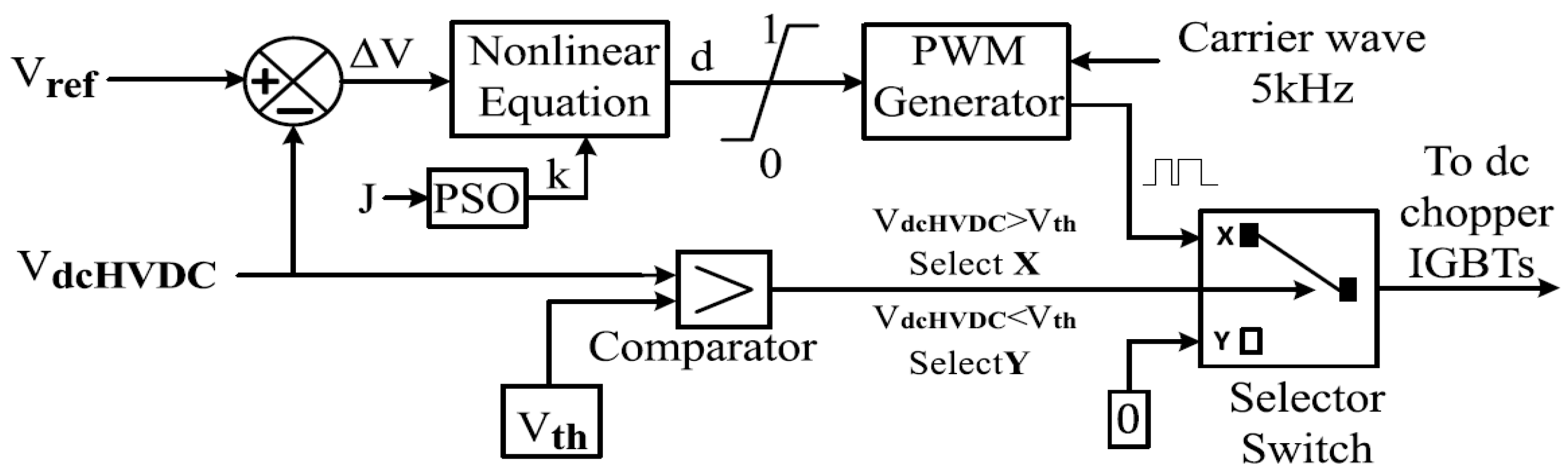
Figure 7.
Convergence curve for objective function.
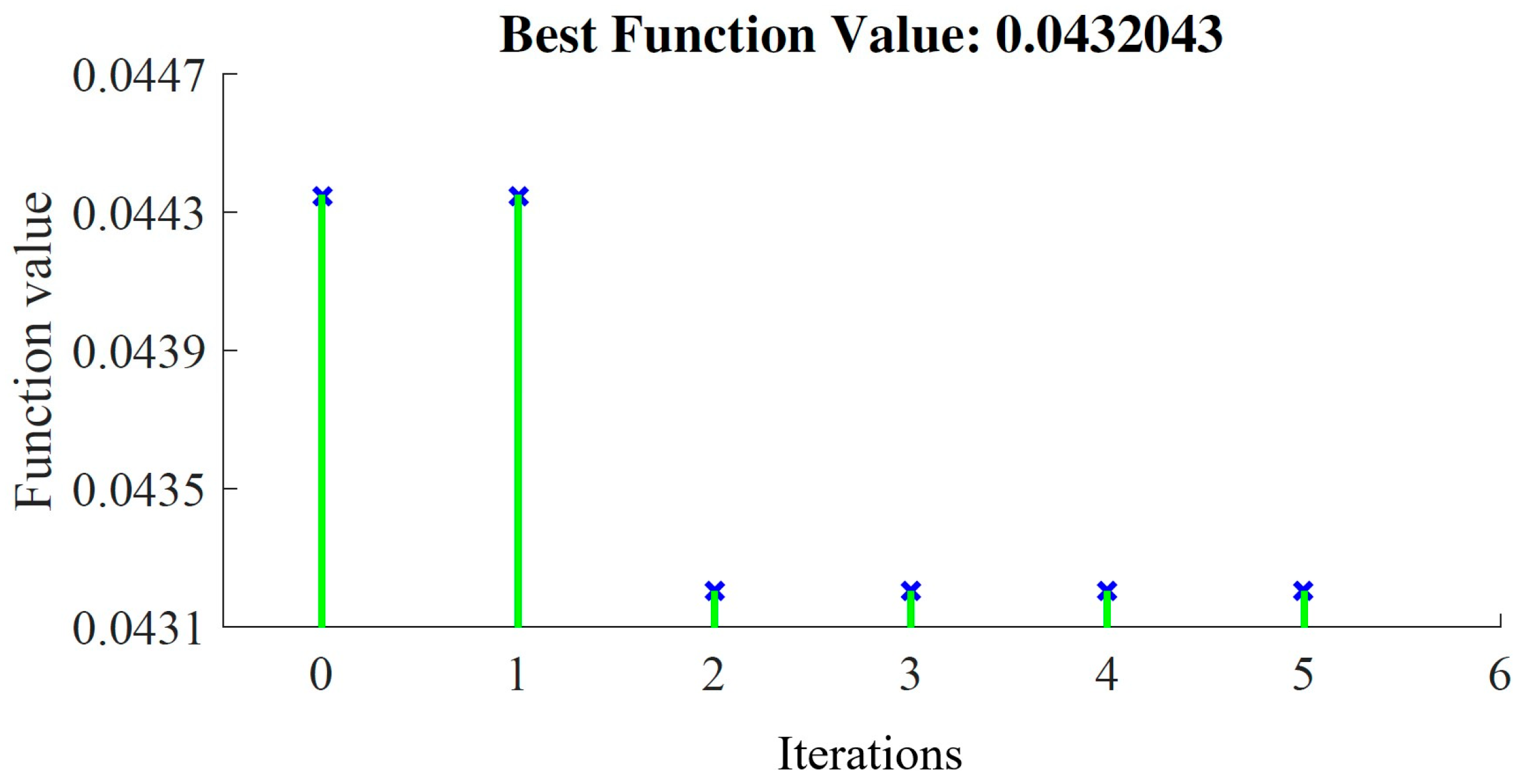
Figure 8.
DC chopper controller.
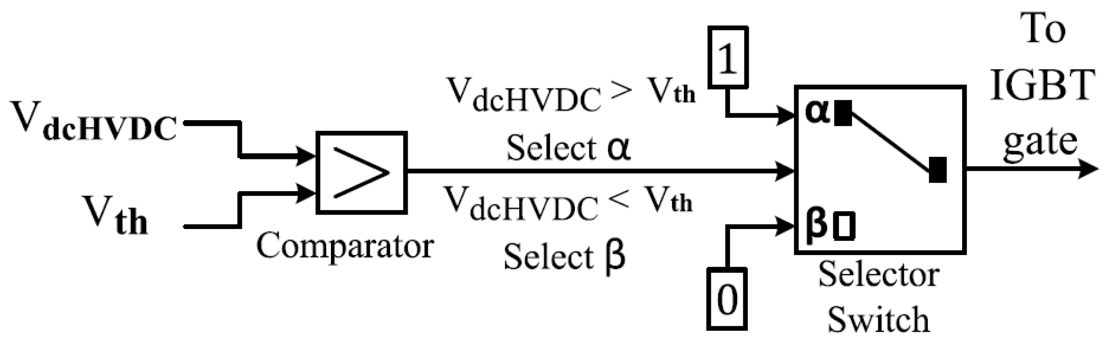
Figure 9.
Offshore wind farm terminal voltage response.
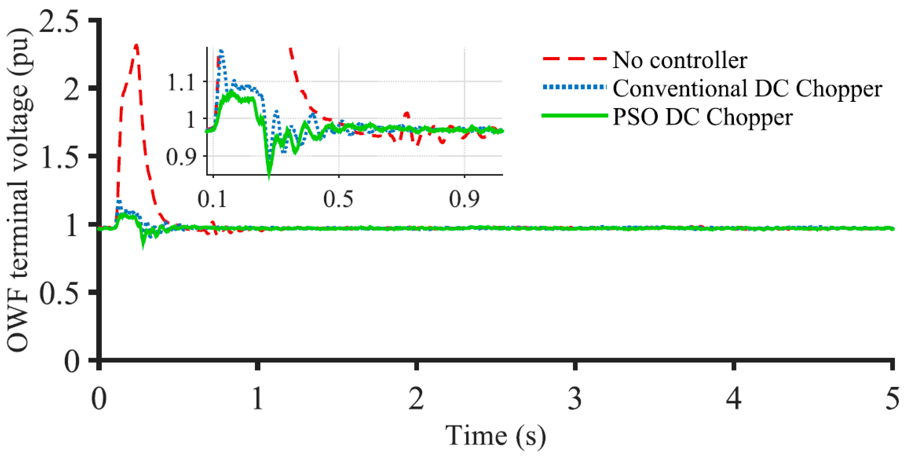
Figure 10.
Offshore wind farm active power response.

Figure 11.
DFIG DC link voltage response.
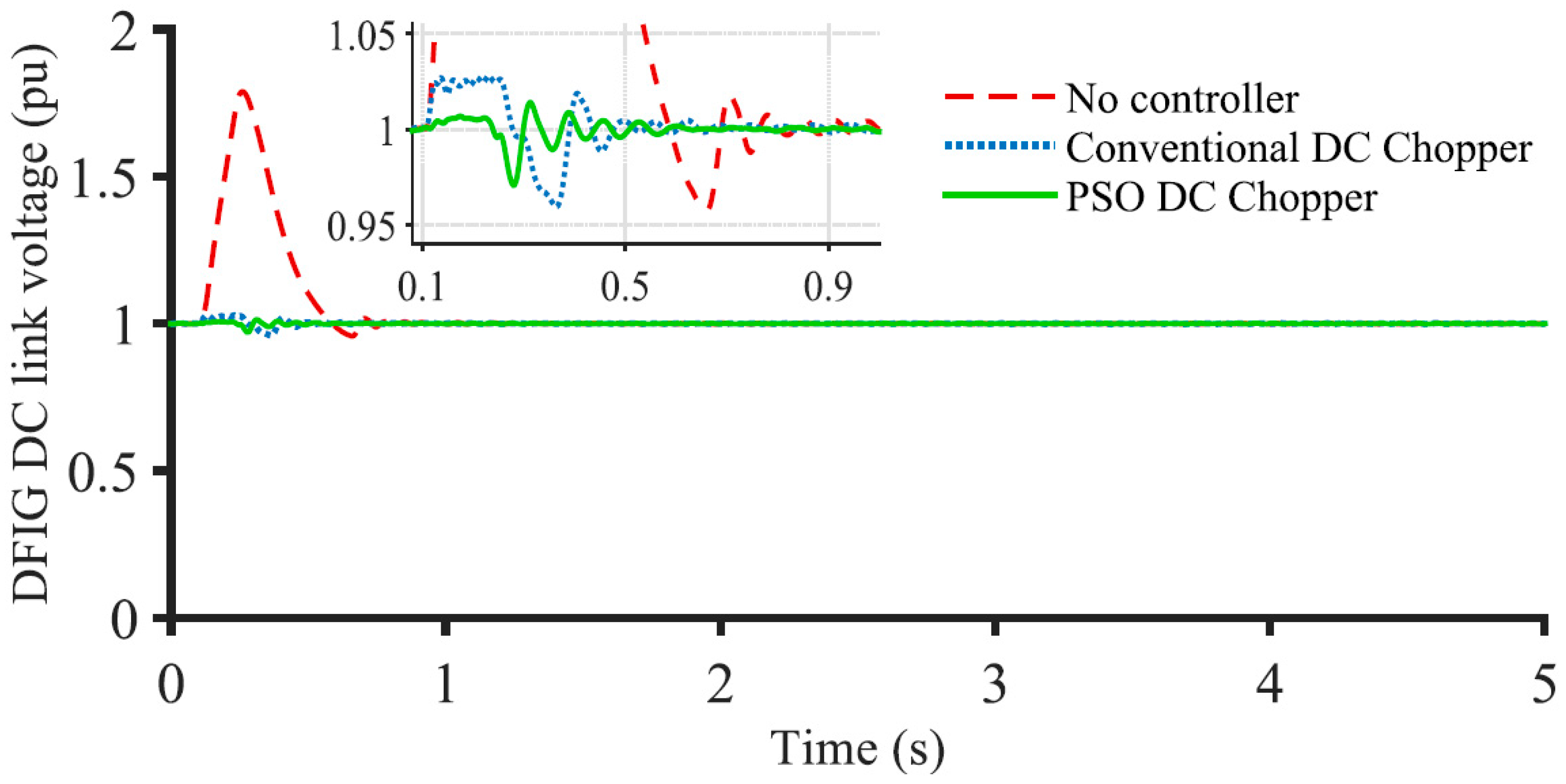
Figure 12.
DFIG speed response.
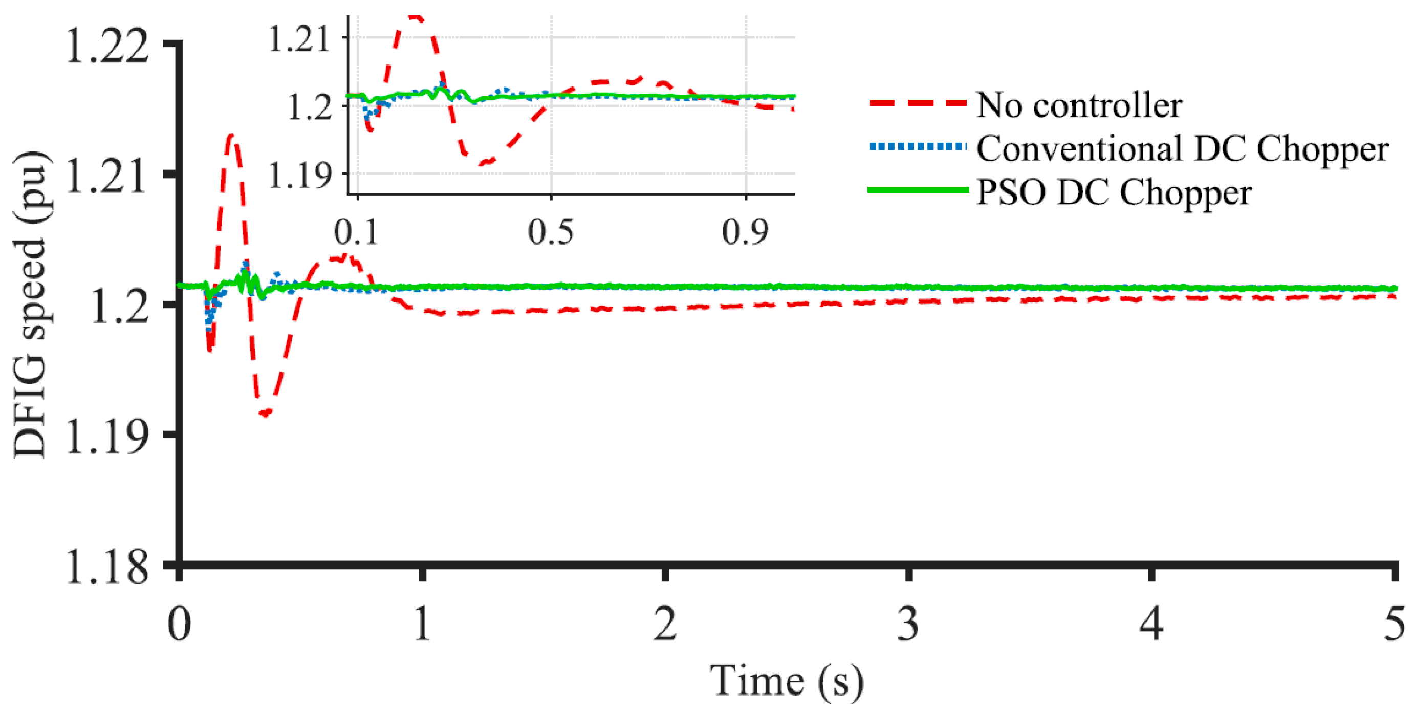
Figure 13.
Sending-end station HVDC line voltage.
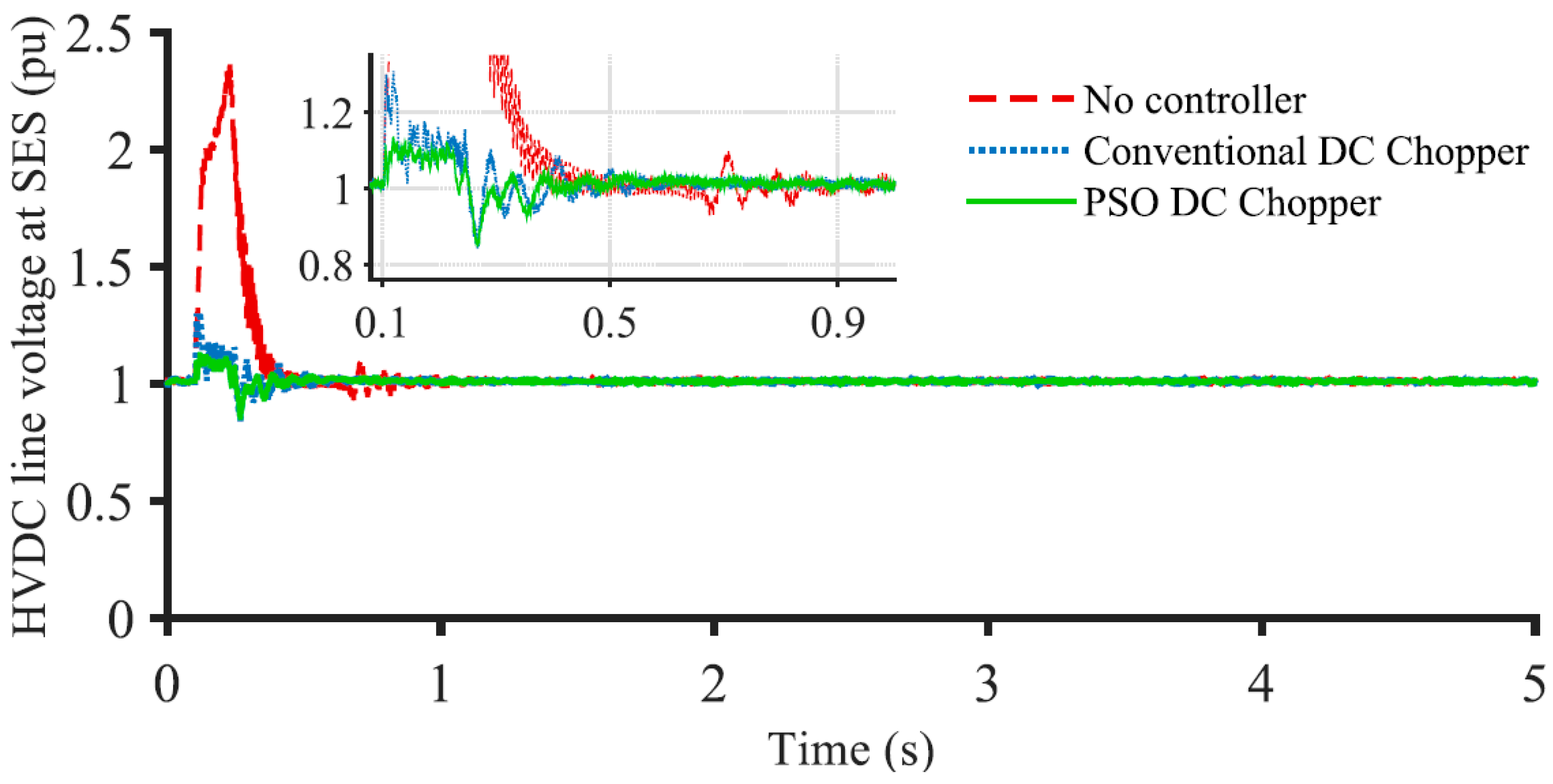
Figure 14.
Receiving-end station HVDC line voltage.
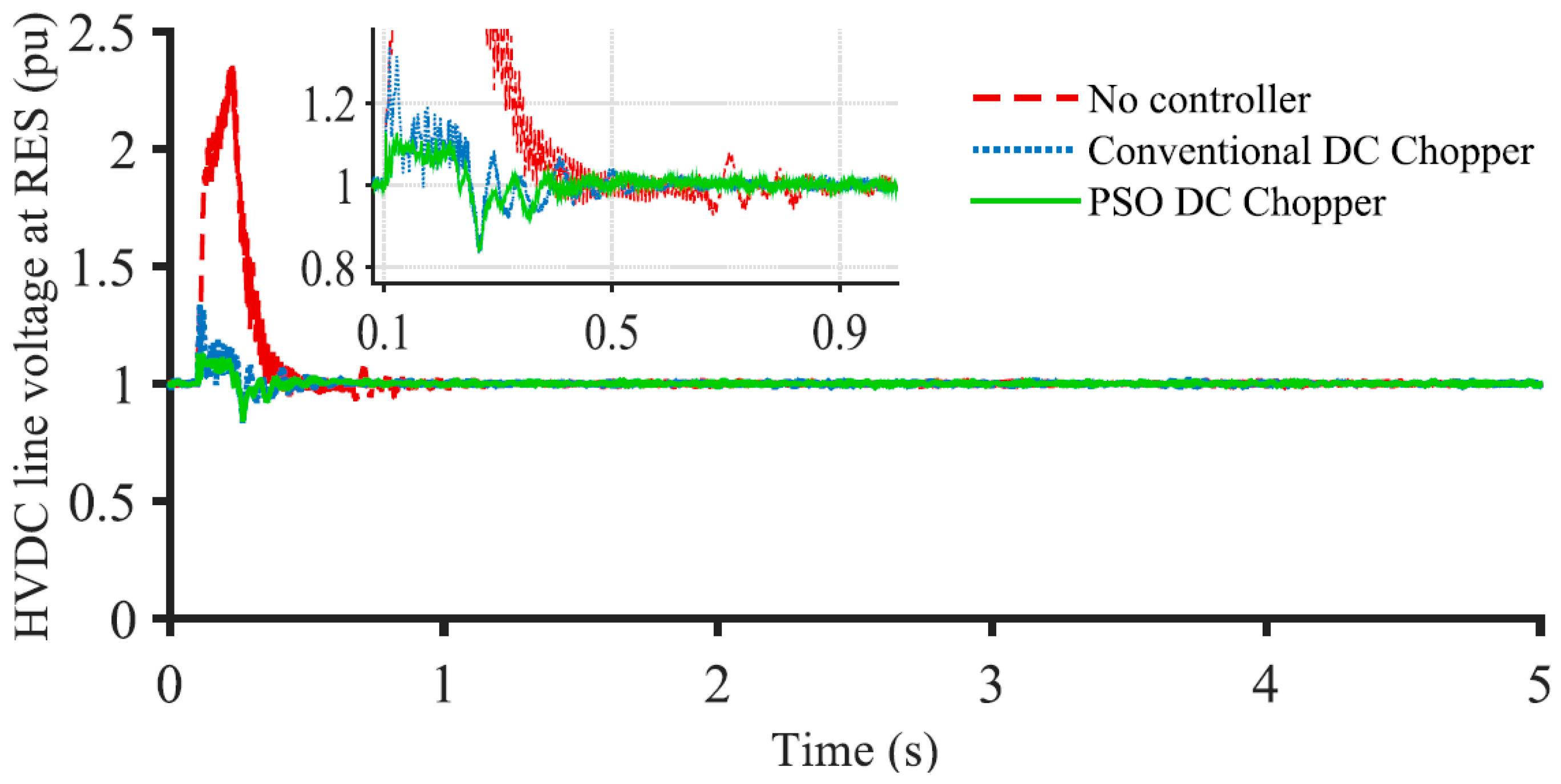
Figure 15.
Onshore grid voltage.
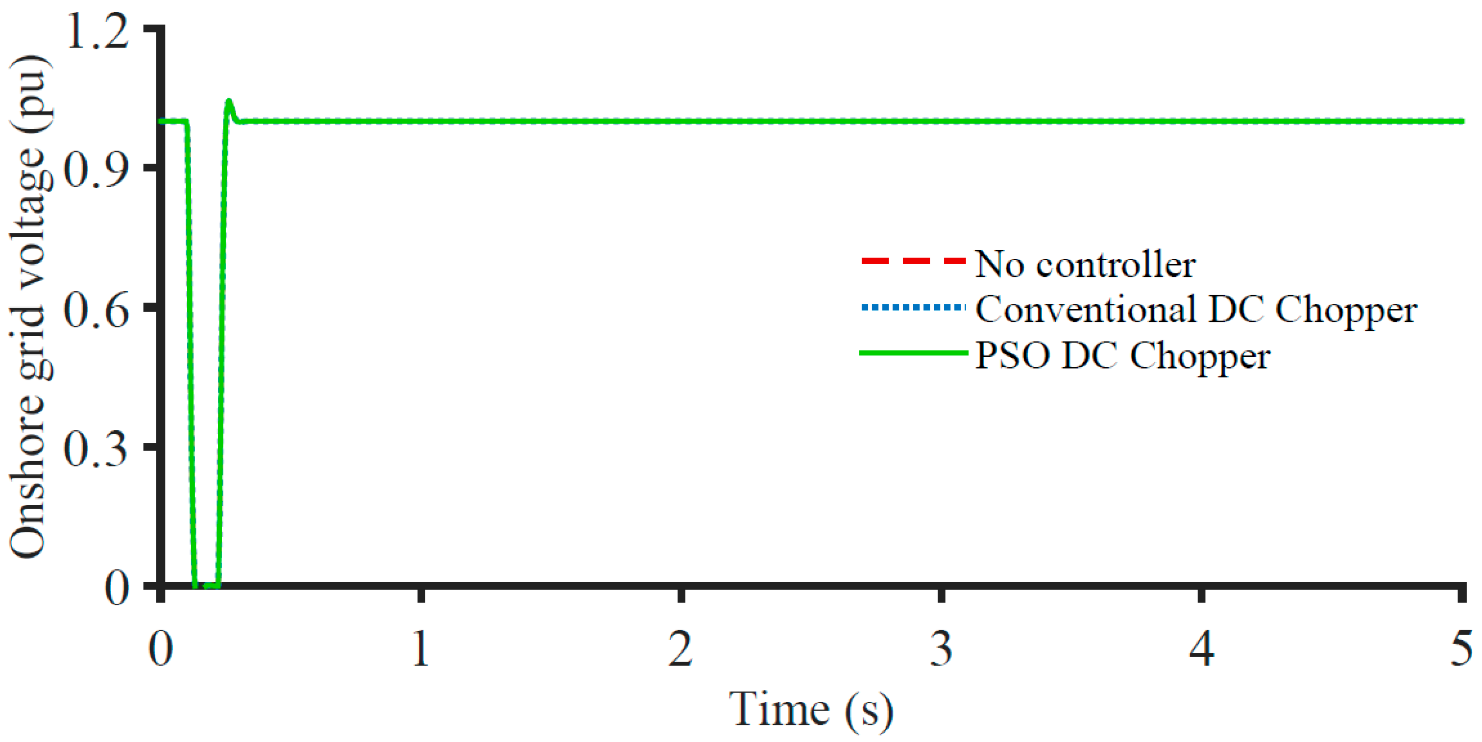
Figure 16.
Dissipated power in DC chopper.

Table 1.
Wind generator and turbine data.
| Characteristics | Value |
|---|---|
| Nominal power | 1.67 MVA |
| Rated voltage (V) | 690 V |
| Stator to rotor turns ratio | 0.3 |
| System frequency | 50 Hz |
| Stator resistance (Rs) | 0.012 pu |
| Stator inductance (Ls) | 0.15 pu (referred to stator) |
| Rotor resistance (Rr) | 0.012 pu |
| Rotor reactance (Lr) | 0.15 pu (referred to stator) |
| Mutual inductance (Lm) | 4 pu |
| DFIG inertia Constant (H) | 0.0685 pu |
| DC link rated voltage (Edc) | 1200 V |
| Turbine inertia constant | 4.32 s |
| Shaft spring constant | 1.11 pu |
| Shaft mutual damping | 1.5 pu |
Table 2.
Values of performance indices for 3LG fault at onshore grid.
| Index Parameters (%) | Values of Indices | ||
|---|---|---|---|
| No Auxiliary Controller | Conventional DC Chopper | PSO-Based DC Chopper | |
| VOWF (pu·s) | 14.85 | 3.96 | 3.19 |
| ωDFIG (pu·s) | 0.74 | 0.11 | 0.08 |
| POWF (pu·s) | 23.51 | 5.12 | 3.80 |
| VdcHVDC (pu·s) | 22.56 | 5.39 | 4.32 |
Disclaimer/Publisher’s Note: The statements, opinions and data contained in all publications are solely those of the individual author(s) and contributor(s) and not of MDPI and/or the editor(s). MDPI and/or the editor(s) disclaim responsibility for any injury to people or property resulting from any ideas, methods, instructions or products referred to in the content. |
© 2023 by the authors. Licensee MDPI, Basel, Switzerland. This article is an open access article distributed under the terms and conditions of the Creative Commons Attribution (CC BY) license (https://creativecommons.org/licenses/by/4.0/).
Share and Cite
MDPI and ACS Style
Rashid, G.; Ali, M.H. FRT Capability Enhancement of Offshore Wind Farm by DC Chopper. Energies 2023, 16, 2129. https://doi.org/10.3390/en16052129
AMA Style
Rashid G, Ali MH. FRT Capability Enhancement of Offshore Wind Farm by DC Chopper. Energies. 2023; 16(5):2129. https://doi.org/10.3390/en16052129
Chicago/Turabian StyleRashid, Gilmanur, and Mohd Hasan Ali. 2023. "FRT Capability Enhancement of Offshore Wind Farm by DC Chopper" Energies 16, no. 5: 2129. https://doi.org/10.3390/en16052129
Note that from the first issue of 2016, this journal uses article numbers instead of page numbers. See further details here.