Abstract
We propose a method for rapid prototyping of a three-phase AC drive system for educational purposes. The proposed method allows college students to design and manufacture a drive system comprising three-phase inverters, a permanent-magnet (PM) machine, a controller, and sensors within a semester. The rapid prototyping process, which requires less than a day, enables efficient iteration and testing during the development process. In addition to addressing the electrical design considerations, this study also addresses the mechanical aspects of the drive system, including the use of coreless PM machines fabricated, using additive manufacturing technology, and the inverter manufacturing process, utilizing an auto-milling machine. Finally, we provide details of the rapid prototyping of closed-loop control, based on sensor feedback to regulate the rotating magnetic fields and output torque.
1. Introduction
An electromechanical energy conversion device converts electrical power (voltage and current) into mechanical power (velocity and force). Typical drive applications adopt more electrical drive systems than internal combustion and hydraulic actuator drive systems [1]. This is because an electrical drive system has faster dynamics, compatibility with other electrical systems, high power conversion efficiency, and low noise [2,3]. Hence, applications, such as robots and electric vehicles, require custom-designed electrical drive systems. The electrical drive system should satisfy the following load specifications: velocity, force, constraints, volume, weight, efficiency, and size.
The drive system is comprised of two key energy-conversion components: an electric machine and an inverter [4]. Each of these system components must be developed by considering the holistic aspects of the system. Optimizing the individual components does not always guarantee optimal performance at the application level. Advanced mobile applications that are sensitive to weight, volume, and shape often require a repetitive design process of the drive system to find an optimal configuration [5].
Developing an electric drive system is a complex and time-consuming process. To streamline the design and manufacturing process, this study explores a rapid-prototyping method for creating an electrical drive system based on 3D-printing technologies [6,7]. By implementing the proposed rapid-prototyping approach, the design can be quickly modified to achieve optimal performance, can rapidly test various drive system configurations, and can troubleshoot any issues that may arise. Additionally, the voltage, current, and velocity parameters of the inverter and machine can be tailored to meet the specific requirements of the application. To facilitate the prototyping process, this study utilized additive and subtractive manufacturing technologies to fabricate an electric machine and inverter, respectively.
This paper presents the rapid design and manufacturing process of a three-phase permanent magnet synchronous machine (PMSM) using a 3D-printer [8,9,10,11,12,13]. A 3D-printed machine can be shaped in both radial and axial direction magnetic flux paths, resulting in an additional degree of freedom on PMSM design. In fact, a 3D-printed motor integrated into an impeller fan has been successfully used to produce direct airflow [10]. The advancement of 3D printing technology has also led to a wider range of materials being available [12], including polymers like polylactic acid (PLA), soft magnetic composite (SMC), acrylonitrile butadiene styrene (ABS), and polyethylene terephthalate glycol-modified (PETG). For instance, the use of magnetic PLA in [13] reduced magnetic leakage and improved the machine’s torque density. Finite element analysis (FEA) was used for an electromagnetic design of the PMSM in [14]. The PMSM design was converted to a standard triangle language (STL) using Computer-Aided Design (CAD) software for additive manufacturing [15]. Four PMSMs with different velocity-torque limits were designed, manufactured, and tested. The time and cost required for the additive manufacturing of the machines were also analyzed and compared.
An inverter converts the ratio, magnitude, and phase of the voltage and current, generating a rotating magnetic field for electromagnetic machines [4,16,17]. To prototype an inverter, engineers can take advantage of using the online design tools offered by power semiconductor manufacturers, such as SEMIKRON and Texas Instruments [18,19]. Inverter circuit analysis and design were performed using a free Spice program and a CAD program [20]. The inverter’s printed circuit board (PCB) was manufactured using a PCB milling machine that utilized subtractive manufacturing.
Recent studies have shown that an accurate machine model can facilitate inexpensive and fast testing and implementation of control algorithms [21,22]. In this study, a microcontroller unit (MCU) with current and position feedback was employed for the closed-loop control of the fabricated machine and inverter. The control algorithm, developed in C programming language, was compiled and uploaded to a commercially-available MCU, the TMS320f28388D, which supports fast peripheral configuration. The control codes were thoroughly tested in a simulation environment and successfully applied to the MCU without modification [23,24,25].
The rapid-prototyping process of the PM machine drive system, consisting of a controller, inverter, PM machine, and sensor (See Figure 1) is presented in the following sections.
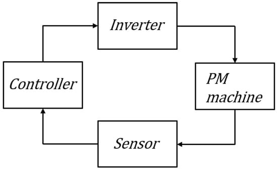
Figure 1.
Closed-loop electric machine drive system block diagram.
2. PM Machine Design and Additive Manufacturing
Figure 1 shows the block diagram of the drive system. Each component of the drive system is connected to a closed loop [26,27]. Figure 2a,b show the additive and subtractive manufacturing processes used for the proposed rapid-prototyping approach.
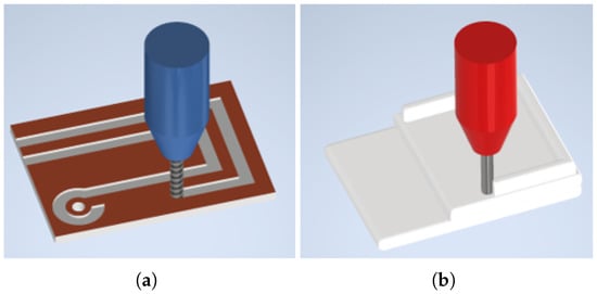
Figure 2.
(a) Subtractive manufacturing used for a printed circuit board, and (b) Additive manufacturing for a printed PM machine.
The preliminary machine design began with the sizing Equations (1) [4]. Machine torque is proportional to the stack length, L, and the square of the diameter, in Figure 3. The airgap area, A, as shown in Figure 3a, is where electromechanical energy conversion occurs. The airgap field strength is proportional to the amount of material in A, which is proportional to D. The torque in (1) is proportional to the square of D, as it is the product of the force and radius. Figure 3b shows the effect of the change in stack length L. The airgap area for energy conversion is also proportional to L. The ratio between D and L in (1) determines the shape of the machine type, pancake or sausage. By designing the torque, the machine power can be determined using the rotating velocity of the rotor.
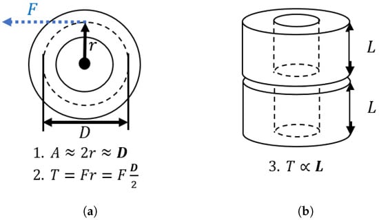
Figure 3.
Machine sizing and torque relationship: (a) Diameter, D, and torque (Top view). (b) Stack length, L, and torque (Side view).
While more advanced analytical techniques, such as lumped parameter circuits and airgap flux density calculations, provide more detailed design options, they can be time-consuming to learn and apply. To streamline the design process, numerous machine engineers turn to FEA. This method divides the area of study into smaller pieces and uses the laws of physics to iteratively solve for the larger area. FEA is particularly useful for multi-physics design, allowing for a detailed analysis of the electromagnetic, thermal, and mechanical domains.
2.1. Electromagnetic Design
The electromagnetic design of the 3D-printed PMSM designs was performed using the free FEA software, FEMM [14]. The design process of the PM machine is illustrated in Figure 4. FEMM allows the capability to incorporate MATLAB functions, thus, allowing for the creation of dots, lines, arcs, and the application of material properties to specific regions. The regions were then meshed and solved for the given boundary conditions, and the resulting data were imported into MATLAB for post-processing and evaluation of the simulated design.
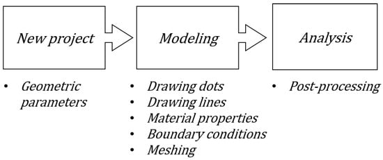
Figure 4.
3D printed machine design process using FEA software.
A template script was developed to design the 3-phase coreless type PM machine, as shown in Figure 5. Various coil and PM locations and shapes could be evaluated using the FEA.
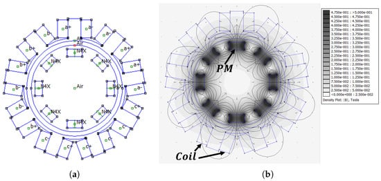
Figure 5.
Finite element analysis (FEA) results. analysis: (a) FEA drawing; and (b) FEA-calculated flux density contour plot.
2.1.1. Material Properties
The two core components of PM machines are permanent magnets and coils. The PMs are placed on the rotating component of the machine, that is, the rotor. PMs provide their own persistent magnetic fields. Therefore, the strength of the PM magnetic field cannot be actively controlled. The direction of the PM magnetic field was synchronized with the rotor position. NdFeB38 grade magnets were used here.
The coils were placed on the stationary part of the PM machine. The 3-phase coil current controlled the magnitude and direction of the armature rotating magnetic field. For this project, a coreless-type machine was chosen to demonstrate the rapid-prototyping process of a 3-phase machine drive system.
Since the stator and rotor cores were made of plastic, the relative permeability of the material was set to 1. If ferromagnetic materials were used, the reluctance would reduce in the flux path to increase the output torque. The MATLAB script was modified to generate various sizes and positions of stator coils and rotor magnets. Each design was evaluated using FEMM.
2.1.2. Coil Winding Configuration and Torque Speed Ratio
A concentration-winding configuration was used for the rapid prototyping process because it had a shorter end-winding length and was easier to manufacture, than machines with distributed windings. Each coil can be represented as a spatial–coil vector placed 120 electrical degrees apart. A fractional-slot concentrated coil winding configuration was found to maximize the winding factor [28]. The coils can be connected in series or in parallel, while maintaining the winding factor.
The inverter input voltage and current ratio can be adjusted using the coil configuration of the machine as follows:
- Large current, high-speed machine:
The magnitude of the phase current can be increased by increasing the coil area. This area can be increased without thermal problems by using a large-diameter coil with fewer turns. The effective coil area can also be increased when phase coils are connected in parallel. Increasing the coil current can decrease the coil voltage to produce constant power.
- Small current, low-speed machine:
A small coil diameter with series-connected phase windings reduces the magnitude of phase currents. The coil voltage can be increased by reducing the phase current to generate a constant amount of power.
2.1.3. Torque Evaluation
The torque evaluation was performed for 0–360° electrical angles, . The FEA model was analyzed in 10° incremental steps as shown in Figure 6a. The phase current densities, in (2), were converted into quantities, , using the -transform in (3). The coil current was calculated by multiplying the coil area and the current density was applied to the phase coil area. Phase current in Figure 6b was calculated given a coil diameter, of 0.35 mm and a coil fill factor of 65% in (4). The average torque and torque ripple were evaluated using FEA.
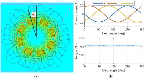
Figure 6.
Torque evaluation using FEA: (a) Electric angle, . (b) 3-phase current and torque.
2.1.4. Losses
The electromagnetic loss components for the plastic 3D-printed PM machine were copper and eddy current losses in the PMs. The losses increased the temperature of the plastic core and deformation of the 3D-printed parts occurred above 60 °C. Only copper loss was considered in the design process, because the eddy current loss component was negligible at low rotating speeds. The maximum current density, , for the FEA simulation was set to 3 to limit the coil temperature.
2.1.5. Design Optimization Results
Once a template script was ready to generate and evaluate the PM machine model, a parametric sweep was performed to determine the optimal locations of the coils and PMs. These parameters were swept manually by creating a for-loop in the script. Design optimization was also conducted using stochastic-based optimization algorithms, such as particle swarm optimization (PSO) and differential evolution (DE).
2.2. Mechanical Design for Additive Manufacturing
The mechanical components were designed using 3D CAD software; Autodesk Inventor was used [15].
The conventional and 3D-printed PM machine slot-opening structures are shown in Figure 7a,b. The 3D-printed machine slot openings for the coil winding were placed on the outer part of the stator. This structure was chosen to accelerate the coil-winding process. The coils were manually wound.
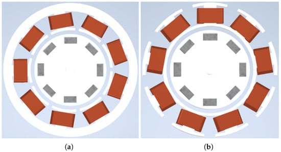
Figure 7.
Stator slot opening design: (a) Conventional machine. (b) 3D-printed machine.
The PMs were then placed in the rotor. Two ball bearings were used to match the centers of the stator and rotor. The top cover was designed to contain a holder for encoder placement.
2.3. Results
Based on the aforementioned machine design process, four student teams designed and manufactured their PM machines. Each team consisted of three junior students. Figure 8 shows four design cases demonstrated by each team. Table 1 shows the specifications for each case. Each design had different parameters. The geometries of the coils and PM shape primarily determined the characteristics of the machine, such as the resistance, inductance, average torque, and torque ripple.
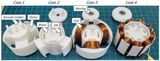
Figure 8.
3D-printed PM machines with mechanical and electromagnetic components.

Table 1.
Rapid prototype PM machine specification.
The machines are comprised of three printed parts: PMs, coils, and bearings. Table 2 shows the material cost for each case. Table 2 shows the material cost of the rapid prototype PM machines shown in Figure 8.
Table 2.
The 3D-printed PM machine material costs.
Table 3 shows the time required to manufacture each PM machine. The time and cost required for additive manufacturing were proportional to the volume of the material. The 3D-printed parts needed post-processing time to remove the supports during the printing process. The 3D printing took the longest time in the manufacturing process. Nevertheless, the 3D printing process was fully automated by the printer until printing was completed. The coil could be wound during 3D printing. The total working time is listed in Table 3 and is discussed in more detail in Section 6.
Table 3.
Time required for 3D-printed PM machine manufacturing process.
Additive manufacturing has shown lower precision and tolerance than conventional manufacturing methods such as milling or lathing. To optimize their designs for 3D printing, the teams had to perform multiple iterations of the printing process to understand the capabilities and limitations of their specific 3D printer. Hence, they could modify their designs to align them with the maximum precision and tolerance achievable with their printer.
3. Inverter Design and Subtractive Manufacturing
This section presents the design and manufacturing process of a 3-phase inverter. The inverter should be designed by considering the loading conditions [16].
The 3-phase inverter in the machine-drive system generates a rotating magnetic field by controlling the current in 3-phase coils. A voltage source inverter (VSI) converts the DC-link voltage to a 3-phase voltage. By controlling the coil voltage, as shown in Figure 9a, the coil current is controlled to produce a rotating magnetic field. By defining the PM flux direction as the d-axis, PMSMs can produce torque by controlling the q-axis current (9), based on Lorenz’s law.
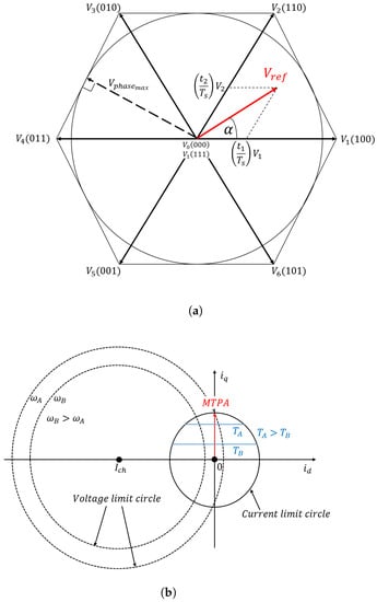
Figure 9.
Drive system voltage and current limit: (a) Inverter voltage limit: Space vector and switching states. (b) PM machine current limit: 3D-printed machine and MTPA.
3.1. Inverter Load, PMSM
The inverter’s DC voltage and current input are converted to a 3-phase voltage and current output. The inverter’s maximum voltage and current are determined by the maximum input voltage and maximum output current of the transistors. However, the maximum capacity of the inverter may not be fully utilized within the load constraints. Therefore, it is important to know the exact amount of load, so as to design the inverter accordingly. The load of the machine drive system was PMSM. The 3-phase PM Machine’s voltage characteristic equations of the three-phase PM machine in the -reference frame are given by (5) and (6). , , , , , and are the phase resistance, inductances, and flux-linkage in -reference frame, respectively. denotes the electrical rotary velocity. -axis flux-linkages in (7) and (8) are cross-coupled in (5) and (6). As the rotor rotates, the time-varying magnetic flux induces a back-EMF voltage in the stator coils.
The torque and machine dynamics equations are given by (9) and (10), respectively. The mechanical rotary velocity, , and electrical rotary velocity relationship are shown in (11), where is the number of poles. , J, and B denote the machine’s load torque, moment of inertia, and viscous density, respectively.
3.1.1. Voltage Limit of Drive System
The input DC voltage to the inverter determines the maximum -voltage. The maximum -voltage Equation (12) is the radius of the inner circle, as shown in Figure 9a in the space–vector plane. Eight switching sequences are shown, where 1 indicates an on-state, and 0 indicates an off-state. A reference voltage, , with angle could be modulated by combining two adjacent states (110 and 100) and zero-sequences (000 or 111). By applying a rotating voltage to the PMSM, the resulting current produced a magnetic field for electromechanical energy conversion.
3.1.2. Current Limit of Drive System
The back-EMF and coupling terms from -transformation could be neglected at zero speed. The PM machine was similar to RL load at zero speed. The inductance terms were neglected by applying a constant voltage. The maximum current with a PM machine load at zero speed was given by (13). The transister’s maximum output current should be lower than that in (13). Demagnetization was not considered because the coreless PM machine considered in this study was difficult to demagnetize by applying an armature current, owing to its low inductance. was limited by both the machine and the inverter’s current limits.
The maximum applicable current output of the drive system had to satisfy the following conditions:
Figure 9b shows the voltage limit circle and the current limit circle. The voltage and current limits were determined by the machine and the inverter, respectively. As coreless machines do not exhibit magnetic saliency, the voltage limit could be represented as a circle. The center of the voltage limit circle was the characteristic current, [5]. The maximum torque per ampere (MTPA) and the current limit circle are shown in Figure 9b. Constant torque lines labeled and are shown. The PM machine drive system could operate inside the current and voltage limit circles.
3.2. Inverter Circuit Design
The inverter analog circuit was designed using Spice software. LTSpice was chosen because it is free, light, and has many examples and component libraries [20]. Figure 10 shows the inverter circuit, which comprises a gate signal generator, a gate driver, and an RL load.
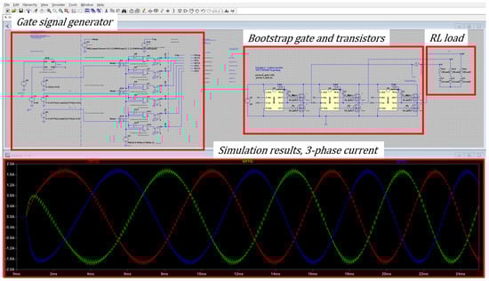
Figure 10.
Inverter circuit simulation block diagram and resulting three-phase current waveforms (LTSpice).
3.2.1. Gate Driver Circuit
To enable pulse width modulation (PWM) with fast-switching transistors, sufficient voltage and current must be supplied. Therefore, the gate signal output from the MCU required an additional gate-drive circuit. The classical gate drive circuits are shown in Figure 11. The single-ended and push-pull drivers for the low-side switches are shown. The high-side switches required an additional drive circuit to supply gate voltage to the load voltage. Typical high-side driver types were isolated, pulse-transited, and boot-strapped. The driver topology can be chosen for power level and budget. This project used a boot-strap driver to develop a cost-effective driver.
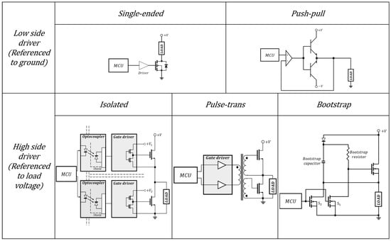
Figure 11.
Gate driver topology for low-side and high-side transistors.
3.2.2. Load Circuit
3.2.3. Gate Signal Generator Circuit
The gate signals for the transistors used logic gates in LTSpice analog circuit simulator. Deadtime was modeled to avoid short circuits between the high- and low-side transistors of the VSI. Bootstrap capacitors and their resistance effect were tested in the inverter design process. In the rapid-prototype setup, PWM gate signals were generated by the MCU to avoid complications.
The PCB milling machine used to fabricate the inverter circuit is shown in Figure 12. The auto-route of the milling machine for manufacturing PCBs is shown in Figure 13. The copper plate spacer adjusted the depth of the end mill bit to the copper plate. The vacuum hose collected copper debris from the milling.
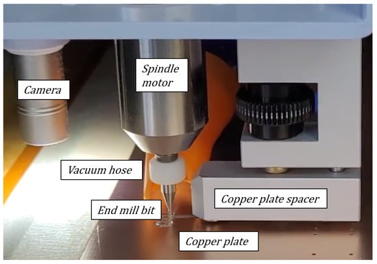
Figure 12.
PCB milling machine used for subtractive manufacturing.
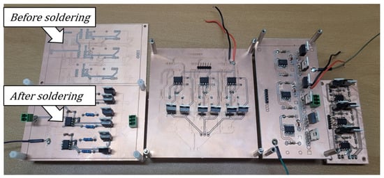
Figure 13.
Inverter PCB manufactured using PCB milling machine.
3.3. PCB Milling Machine and Subtractive Manufacturing
PCB Layout for PCB Milling Machine
KiCad was used for the inverter circuit layout. KiCad is an easy-to-use free software. Inverter components were checked to determine the size and location of the drill holes. The minimum track width of the PCB was calculated according to the IPC-2221 standard.
Table 4 shows the costs of the inverter material. Different PCB layouts and copper plate areas were used for each case. The average cost of manufacturing an inverter is shown below $6.
Table 4.
Inverter material cost.
Table 5 shows the average time required to manufacture the inverter. The average time to soldering was calculated a 10 s per solder point. The inverter was manufactured in 2 h.
Table 5.
Inverter manufacturing time.
4. Control
This section presents a controller for completing the drive system. Real-time control algorithms and protection codes were tested in a simulation environment coded in C language in MATLAB Simulink. The same C code tested in the simulation environment was used in the controller without modification to accelerate the development process. The peripheral hardware configuration of the MCU was configured using SysConfig, a tool to auto-generate the code to configure peripherals.
4.1. Controller Simulation
Figure 14 shows the block diagram of the controller simulation. The upper blocks represent the system model, comprising -transform, PM machine voltage model, inverse -transform, PM machine torque model, and PM machine kinematics model. The lower block represents the MCU coded in the C programming language, where MinGW-w64 C/C++ was used as the compiler. The interrupt frequency was set to 10 kHz. The inputs to the MCU were the 3-phase current input and the rotor position. The outputs of the MCU were a 3-phase duty ratio and signals for the program check. A classical vector controller was implemented in C to control the torque, velocity, and position in a cascaded manner. Protection codes, such as anti-windup, maximum current limiter, and maximum duty ratio limiter, were also tested in the simulation environment. Control algorithms can be rapidly developed and tested in a simulation environment. The tested code can be transferred to a real-time controller without code modification.
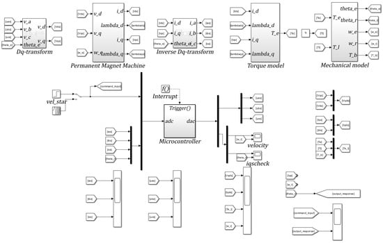
Figure 14.
Digital controller simulation block diagram including machine electrical and mechanical models.
The simulation results of the digital controller are presented in Figure 15. A swept sine velocity input, ranging from 0 to 50 Hz, was used for 0 to 5 s, as shown in Figure 15a. The controller bandwidths for the current and velocity loops were set to 300 Hz and 25 Hz, respectively. As a result, the resulting velocity response could not follow the velocity command beyond 2.5 s. The torque was proportional to the q-axis current, where the current limit was set to 2, as shown in Figure 15b,c. The d-axis current was controlled to 0, since no additional torque could be produced for the SPMSM (9). The phase currents after the inverse -transformation are shown in Figure 15d. Feasible input profiles under various load conditions could be tested in this simulation environment. The simulation also served as a platform for testing and debugging the digital control algorithm, which was implemented on a real-time microcontroller.
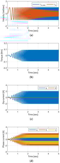
Figure 15.
Simulation results with swept sine velocity input (1 rad/sec 0 to 50 Hz in 5 s), velocity loop bandwidth (25 Hz), current loop bandwidth (300 Hz), current limit (2) (a) Velocity command and response. (b) Torque output. (c) -current responses. (d) Phase current responses.
4.2. Controller Hardware Configuration
The TMS320f288388D, from Texas Instruments, was used to implement the controller in the digital domain. The SysConfig menu was used for the peripheral hardware setup, that is, a 12-bit analog-to-digital converter (ADC), 3-phase PWM, quadrature encoder digital input, and a digital controller were used by implementing the 3-phase PWM sequence in the MCU. Two current sensors were connected to microcontroller feedback through a 12-bit ADC. We used 5120 pulse-per-revolution encoders to track the rotor position. We configured 10 kHz PWM switching frequency with 1 μs of deadtime. Dead time prevented DC link voltage short circuits during vector control, which used three switches in each sequence. A 200 MHz system clock frequency was divided to generate a 10 kHz interrupt, which would read the ADC and encoder, and update the duty ratio of the PWM. Sharing the reference voltage for the digital and analog ground was important, to avoid floating voltage.
5. Machine Drive System
A block diagram of the machine drive system is shown in Figure 16a. Each component had to function as planned to complete a closed loop. The rapid prototype machine in Section 2 and inverter in Section 3 were connected for energy conversion testing. A current–vector controller was implemented for torque control. A classical proportional–integral (PI) controller was applied to the velocity and position controllers. The encoder position was used for -transform to track the rotating magnetic field of the PM rotor. For closed-loop control of the energy conversion devices, sensor feedback to the MCU and gate signal outputs were provided as inputs to the inverter.
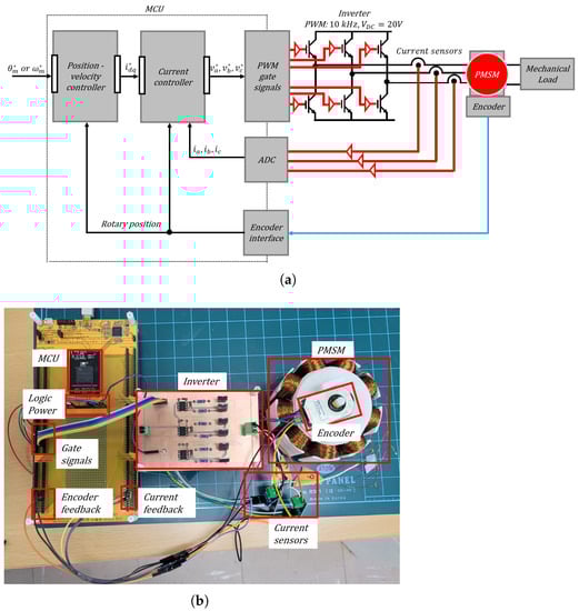
Figure 16.
Rapid-prototyed machine drive system. (a) Drive system block diagram. (b) Rapid-prototyped drive system.
Figure 16b shows an 8-pole/9-slot PMSM drive system. A DC link voltage of 20 V was supplied using a DC power supply. The encoder was placed on top of the machine, as shown in the figure. Using a linear voltage regulator, the evaluation board supplied the low-voltage input to the MCU, encoder, and current sensors.
The experimental results of the drive system are shown in Figure 17. As shown in Figure 17a, the PWM output to the gate drive switched at 10 kHz frequency with a deadtime of 1 ms to avoid shoot-through faults. The gate driver would turn on the upper and lower switches to modulate phase voltages. The resulting phase current responses are shown in Figure 17b, which would result in torque to accelerate the rotor. The quadrature encoder signals in Figure 17c were to track the rotor position, based on quadrature digital signals. The channel A and channel B outputs were 90 degrees out of phase with each other, with channel A leading when the rotor rotated counterclockwise. The encoder pulse-per-resolution (PPR) was set to 5120. The encoder signals were converted to electrical angles and used for -transformation and velocity estimation. By tracking the rotor position, the direction of the PM flux linkage orientation could be tracked to produce the commanded torque.
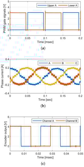
Figure 17.
Experimental results. (a) Phase-a PWM signals for upper and lower switches (PWM switching frequency = 10 kHz, deadtime = 1 ms). (b) Phase current responses. (c) Channel A and channel B output of a quadrature encoder.
5.1. Machine Drive System Test
The drive system was used for power conversion. To test whether the drive system satisfied the application requirements, for example, maximum velocity and torque, the following procedure was used.
5.1.1. D-Axis Alignment
It was important to determine the d-axis in (9) for the maximum torque production per Ampere (MTPA) of the magnet torque. was reduced to with a rotary-angle offset error , as shown in (14).
To operate the machine on MTPA, d-axis voltage of 5% was commanded at no-load for 3 s to align the rotor position with the d-axis. The position feedback from the encoder was set to zero after the 3 s, before starting the machine.
5.1.2. Maximum Rotary Velocity Test
The inductance of coreless type PMSMs was too small to apply field-weakening control, which superimposed a negative d-axis current to flux linkage variation regarding time, that is, the Back-EMF voltage. Conventional zero controllers were used to check the maximum velocity of the drive system. The maximum q-axis voltage was commanded at no-load, while disabling all closed-loop control actions. The voltage Equation (6) became (15) at no-load. The encoder feedback was used only for the -transformation. The velocity of the machine reached its maximum when the Back-EMF reached approximately 50% of the DC-link voltage (12).
5.1.3. Maximum Torque Test
The maximum q-axis voltage was commanded under the locked-rotor condition. At zero speed, the voltage Equation (6) became (16), where the maximum applicable was in (12). The resulting q-axis current produced torque in (9). For thermal reasons, the maximum torque was limited by the maximum coil current.
6. Discussion
The rapid prototype drive system course was taught as a semester course in the fall of 2022 at Koreatech. Each team had to learn how to prototype their design of PM machines and inverters. Each team built inverters and machines multiple times during the learning process. At the end of the semester, the students could reproduce the driving system in a day.
The Gantt chart in Figure 18 shows the schedule for reproducing the drive system. The grey bar represents the work performed by the machine. The 3D printer and PCB milling machine were auto-routed once the CAD file had been set up. The light blue bar indicates the hands-on working hours. The stator of the motor required the longest time to print and, thus, the stator was printed first. The inverter was manufactured by printing the stator. The coils were wound while printing the rotor and encoder holder. The drive system was manufactured in 18 h. The average material costs to build the machine and inverter were $18.23 and $5.45, respectively. However, the price could vary with the power ratings of the inverter transistors and the number of coils and PMs.
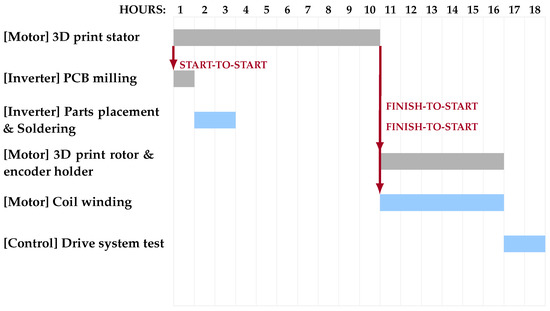
Figure 18.
Inverter, motor, and controller rapid prototyping schedule.
Fast design modification and debugging processes were possible at a low cost, using the proposed rapid prototyping process. In addition, this process was helpful for students learning system-level engineering.
7. Conclusions
This study investigated a methodology for a rapid-prototype drive system to shorten the development cycle, debugging, and modification processes. A 3D-printer was used for the additive manufacturing of PMSMs. A PCB milling machine was used for the subtractive manufacturing of the inverters. The average time and cost required to prototype an educational drive system were 18 h and $24, respectively. Four sets of drive systems, with different torque and speed characteristics, were manufactured. The design modification and debugging process became more efficient by employing a rapid prototyping process. The lessons learned from drive system design and debugging processes are discussed to assist engineers in developing similar prototyping methodologies. System-level engineering can be achieved by designing and manufacturing each drive system component.
The proposed approach also has the potential to rapidly prototype reluctance torque machines, for example, interior PM machines made of ferromagnetic materials. Moreover, a similar prototyping process can be developed for PM machines made of sheet molding compounds (SMC) or laminated silicon sheets. Drive systems with higher power ratings can also be rapidly designed and manufactured by increasing the ratings of transistors and machine size.
Future work will include integration of the inverter, MCU, and current sensor in a single PCB. This will reduce the number of lead wires, which are noise sources. In addition, a machine input and output power measurement system will be developed to evaluate the drive system over its entire operating range.
Author Contributions
Conceptualization, methodology, formal analysis, writing—original draft preparation, Y.G.K.; writing—original draft preparation, K.M.L.; writing—review and editing, G.C. All authors have read and agreed to the published version of the manuscript.
Funding
This paper was supported by an INHA UNIVERSITY Research Grant.
Data Availability Statement
Not applicable.
Conflicts of Interest
The authors declare no conflict of interest.
References
- Sul, S.K. Control of Electric Machine Drive Systems; John Wiley & Sons: New York, NY, USA, 2011. [Google Scholar]
- Nam, K.H. AC Motor Control and Electric Vehicle Applications; CRC Press: Boca Caton, FL, USA, 2017. [Google Scholar]
- Krause, P.C.; Wasynczuk, O.; Sudhoff, S.D.; Pekarek, S.D. Analysis of Electric Machinery and Drive Systems; John Wiley & Sons: New York, NY, USA, 2013; Volume 75. [Google Scholar]
- Hanselman, D.C. Brushless Permanent Magnet Motor Design; The Writers’ Collective: Cranston, RI, USA, 2003. [Google Scholar]
- Lipo, T.A. Introduction to AC Machine Design; John Wiley & Sons: New York, NY, USA, 2017. [Google Scholar]
- Ford, S.; Minshall, T. Invited review article: Where and how 3D printing is used in teaching and education. Addit. Manuf. 2019, 25, 131–150. [Google Scholar] [CrossRef]
- Karakas, E.; Tekindal, S. The Effects of Computer-Assisted Learning in Teaching Permanent Magnet Synchronous Motors. IEEE Trans. Educ. 2008, 51, 448–455. [Google Scholar] [CrossRef]
- Zhang, Z.Y.; Jhong, K.J.; Cheng, C.W.; Huang, P.W.; Tsai, M.C.; Lee, W.H. Metal 3D printing of synchronous reluctance motor. In Proceedings of the 2016 IEEE International Conference on Industrial Technology (ICIT), Taipei, Taiwan, 14–17 March 2016; pp. 1125–1128. [Google Scholar] [CrossRef]
- Pyo, H.J.; Jeong, J.W.; Yu, J.; Lee, S.G.; Kim, W.H. Design of 3D-Printed Hybrid Axial-Flux Motor Using 3D-Printed SMC Core. IEEE Trans. Appl. Supercond. 2020, 30, 5202004. [Google Scholar] [CrossRef]
- Wu, S.T.; Huang, P.W.; Chang, T.W.; Jiang, I.H.; Tsai, M.C. Application of Magnetic Metal 3-D Printing on the Integration of Axial-Flow Impeller Fan Motor Design. IEEE Trans. Magn. 2021, 57, 8201205. [Google Scholar] [CrossRef]
- Groenhuis, V.; Stramigioli, S. Rapid Prototyping High-Performance MR Safe Pneumatic Stepper Motors. IEEE/ASME Trans. Mechatron. 2018, 23, 1843–1853. [Google Scholar] [CrossRef]
- Jhong, K.J.; Chang, T.W.; Lee, W.H.; Tsai, M.C.; Jiang, I.H. Characteristic of high frequency Fe-Si-Cr material for motor application by selective laser melting. AIP Adv. 2019, 9, 035317. [Google Scholar] [CrossRef]
- Stakhiv, H.; Solomchak, O.; Lasek, P.; Stepien, M. FEM Simulation and Analysis of a Concept 3D Printed Electric Motor with Permanent Magnets. In Proceedings of the 2021 IEEE 19th International Power Electronics and Motion Control Conference (PEMC), Gliwice, Poland, 25–29 April 2021; pp. 656–660. [Google Scholar] [CrossRef]
- Meeker, D. FEMM 4.2. In User’s Manual, Virginia; University of Virginia: Charlottesville, VA, USA, 2009. [Google Scholar]
- Waguespack, C. Mastering Autodesk Inventor 2014 and Autodesk Inventor LT 2014: Autodesk Official Press; John Wiley & Sons: New York, NY, USA, 2013. [Google Scholar]
- Mohan, N.; Undeland, T.M.; Robbins, W.P. Power electronics: Converters, Applications, and Design; John Wiley & Sons: New York, NY, USA, 2003. [Google Scholar]
- Luo, Y.; Awal, M.A.; Yu, W.; Husain, I. FPGA implementation for rapid prototyping of high performance voltage source inverters. CPSS Trans. Power Electron. Appl. 2021, 6, 320–331. [Google Scholar] [CrossRef]
- SEMIKRON. SEMISEL—Online Power Semiconductor Simulation Tool for Loss and Temperature Analysis. Available online: https://semisel.semikron.com/#/home (accessed on 2 December 2022).
- Texas Instruments. TINA—SPICE-Based Analog Simulation Program. Available online: https://www.ti.com/tool/TINA-TI (accessed on 2 December 2022).
- Engelhardt, M. LTspice Manual. Accessed: Jul 2011, 25, 2018. [Google Scholar]
- Kenny, S.S.K.; Naayagi, R.; Lee, S.S.; Shuyu, C. Three Phase VSI Control System Rapid Prototyping with TI C2000 MCU and PLECS Coder. In Proceedings of the 2021 5th International Conference on Green Energy and Applications (ICGEA), Singapore, 6–8 March 2021; pp. 42–46. [Google Scholar] [CrossRef]
- Bruno, A.; Caruso, M.; Di Tommaso, A.O.; Miceli, R.; Nevoloso, C.; Viola, F. Simple and flexible power loss minimizer with low-cost MCU implementation for high-efficiency three-phase induction motor drives. IEEE Trans. Ind. Appl. 2021, 57, 1472–1481. [Google Scholar] [CrossRef]
- Versele, J.; Deblecker, O.; Lobry, J. Implementation of Induction Motor Drive Control Schemes in MATLAB/Simulink/dSPACE Envionment for Educational Purpose. In MATLAB for Engineers-Applications in Control, Electrical Engineering, IT and Robotics; IntechOpen: London, UK, 2011; pp. 365–386. [Google Scholar]
- Leedy, A.W. Simulink/MATLAB dynamic induction motor model for use in undergraduate electric machines and power electronics courses. In Proceedings of the 2013 Proceedings of IEEE Southeastcon, Jacksonville, FL, USA, 4–7 April 2013; pp. 1–6. [Google Scholar] [CrossRef]
- Rubaai, A.; Castro-Sitiriche, M.J.; Ofoli, A.R. Design and Implementation of Parallel Fuzzy PID Controller for High-Performance Brushless Motor Drives: An Integrated Environment for Rapid Control Prototyping. IEEE Trans. Ind. Appl. 2008, 44, 1090–1098. [Google Scholar] [CrossRef]
- Meah, K.; Hietpas, S.; Ula, S. Rapid Control Prototyping of a Permanent Magnet DC Motor Drive System using dSPACE and Mathworks Simulink. In Proceedings of the APEC 07—Twenty-Second Annual IEEE Applied Power Electronics Conference and Exposition, Anaheim, CA, USA, 25 February–1 March 2007; pp. 856–861. [Google Scholar] [CrossRef]
- Foster, E.B.; Julian, A.L.; Oriti, G.; Storm, M.P. Rapid Prototyping of Model Predictive Control in a Grid-Following Three-Phase Inverter to Meet the Conducted EMI Limits in MIL-STD-461G. In Proceedings of the 2022 IEEE Energy Conversion Congress and Exposition (ECCE), Detroit, MI, USA, 9–13 October 2022; pp. 1–7. [Google Scholar] [CrossRef]
- Libert, F.; Soulard, J. Investigation on pole-slot combinations for permanent-magnet machines with concentrated windings. In Proceedings of the ICEM, Lodz, Poland, 5–8 September 2004; pp. 530–535. [Google Scholar]


Disclaimer/Publisher’s Note: The statements, opinions and data contained in all publications are solely those of the individual author(s) and contributor(s) and not of MDPI and/or the editor(s). MDPI and/or the editor(s) disclaim responsibility for any injury to people or property resulting from any ideas, methods, instructions or products referred to in the content. |
© 2023 by the authors. Licensee MDPI, Basel, Switzerland. This article is an open access article distributed under the terms and conditions of the Creative Commons Attribution (CC BY) license (https://creativecommons.org/licenses/by/4.0/).