Article

Simulation for the Effect of Singlet Fission Mechanism of Tetracene on Perovskite Solar Cell

Department of Mechanical Engineering, University of Kansas, 3138 Learned Hall, 1530 W. 15th Street, Lawrence, KS 66045, USA
*
Author to whom correspondence should be addressed.
Energies 2023, 16(5), 2428; https://doi.org/10.3390/en16052428
Submission received: 7 February 2023 / Revised: 22 February 2023 / Accepted: 1 March 2023 / Published: 3 March 2023

Abstract

:
The perovskite solar cell has recently gained momentum within the renewable energy industry due to its unique advantages such as high efficiency and cost-effectiveness. However, its instability remains a challenge to its commercialization. In this study, a singlet fission material, namely tetracene, is coupled with the perovskite solar cell to simulate its effect on the solar cell. The amount of thermalization loss and the temperature of the perovskite layer are simulated and analyzed to indicate the mechanism’s effectiveness. We found that coupling the tetracene layer resulted in a drastic reduction in thermalization loss and a slower slope in perovskite layer temperature. This indicates that tetracene would stabilize the perovskite solar cell and minimize its potential losses. The thickness of the solar cell layers is also analyzed as a factor of the overall effectiveness of singlet fission on solar cells.

1. Introduction

With the increase in demand for global energy consumption and the pressing matter of climate change, the development of renewable energy is vital to technological innovation and reducing the adverse impact of energy consumption on the climate. Many possible solutions are being offered, such as wind turbines [1] and thermoelectricity [2,3]. Among them, the photovoltaic (PV) solar cell shows tremendous potential due to its high efficiency and minimal maintenance requirements compared to other renewable options. Although silicon solar cells still dominate the field, attention is turning to perovskite semiconductors [4,5,6]. Perovskite is a term used to describe a class of material with a crystal structure of ABX3, where A is an organic cation, B is a metal cation, and X is a halide anion. It has been used mainly as a photocatalyst for various applications, such as polymerization [7,8] and CO2 reduction [9]. It has also been used in the creation of efficient LEDs [10]. Perovskite is also known as a potent candidate in the photovoltaic field. While the perovskite PV solar cell only entered the competition in 2012, the field has evolved rapidly, with its current efficiency surpassing 20% [11]. Additionally, its Shockley–Queisser limit, which indicates the maximum theoretical efficiency of a single p-n junction, is around 33.7%, which indicates that there is still much room for development [12]. In comparison, that of the silicon solar cell is 26.7% [13]. Apart from using pure perovskite PV solar cells, it can be used alongside silicon to form a tandem device that could exceed 30% efficiency [14]. Besides its high energy conversion efficiency, another advantage of the perovskite PV solar cell lies in its manufacturability. For silicon solar panels, the material must go through a costly process to be manufactured [15]. Using its thin-film nature, perovskite can be fabricated using low-cost techniques, such as inkjet printing [16] or the roll-to-roll technique [17], thus enabling the material to be mass-produced. Aside from its low manufacturing cost, the thin-film attribute also allows perovskite to be used in small devices, allowing more potential applications for the material.
One major setback preventing the commercialization of perovskite is its instability [18,19]. This issue arises when the perovskite layer is exposed to the working environment. One of the leading aspects that cause this degradation process is moisture, which triggers the reaction leading to material degradation [20]. To be more specific, with 98% relative humidity, the absorption of the material is dropped to half of its initial value with only 4 h of exposure to the environment [20]. In contrast, in the case of low relative humidity (20%), the above-mentioned degradation process would take up to 10,000 h [20]. Another reason for the degradation of the perovskite solar cell is due to UV light, or rather, the lack of UV light. A study was conducted to measure the degradation of the electron transport layer TiO2 under different UV conditions. Surprisingly, a capsulated solar cell from UV light degraded the fastest among the cases involved in the study [21]. Temperature also plays a role in the degradation of the solar cell. The production process of the perovskite layer requires an annealing step, where it is required to go through elevated temperatures and eventually be exposed to high temperatures during operation [22,23]. Overall, the results from those experiments consistently showed that the more heat is applied, the faster the cell degrades over time, although at different rates depending on the test conducted (in an N2 environment, ultra-high pressure, etc.). There have been many attempts to improve the stability of the perovskite solar cell. For example, to improve the reliability of the solar cell, substitute materials were used [24,25]. The most common perovskite material is CH3NH3PbI3. By substituting Iodine/Chlorine ions with Bromine ions [26], the material’s crystal structure could be changed, depending on the amount of Bromine ions in the compounds. On top of that, varying the Bromine content also changes the bandgap value of the material, which can improve the efficiency of the solar cell [26].
In addition to the above instability issue, many other factors contribute to the deficit between the energy received from sunlight and the energy extracted from the perovskite PV solar cell. The two most significant factors among them, which accounted for over 50% of the total absorbed solar energy in the solar cell, are the thermalization loss and the non-absorption of below-bandgap photons [27]. Both losses occur in solar cells made of silicon and perovskite. A thermalization process will occur when a solar cell is hit with a photon that carries higher energy than needed for the electron to cross the band gap. In this process, the excess energy relaxes down to the band edge that is lost as heat (i.e., thermalization loss). In turn, the heat generated from this process causes the solar cell to heat up, which will cause it to degrade. In contrast, the band gap loss occurs when the photon does not meet the energy criteria to excite the electron. These photons will pass through the solar cell without being absorbed by the device. The calculated bandgap required for the semiconductor to achieve the Shockley–Queisser limit is 1.34 eV [28], which is higher than the average band gap of perovskite materials. This leads to a higher interest in lowering the bandgap of perovskite. However, simply lowering the bandgap would increase the thermalization loss of the device, which causes the material to degrade. Therefore, further effort to minimize the efficiency loss without directly changing the bandgap is needed.
Among many attempts to address the thermalization loss [29,30,31], singlet fission could potentially minimize the thermalization loss and slow the heating process in a semiconductor [32]. Singlet fission is a process in which one singlet excited state electron is converted into two triplet state excitons [33]. In other words, singlet fission allows the absorption of photons with high energy, such as photons in the ultraviolet spectrum, and converts them into a pair of excitons instead of one free electron. Each exciton created would have less energy than a singlet state electron, reducing the thermalization loss mentioned above. Therefore, with the Shockley–Queisser limit being constructed with the thermalization loss accounted for, using singlet fission could potentially make the device’s energy conversion efficiency surpass this limit by up to about 45% in the case of silicon solar cells [34]. So far, singlet fission has been proposed for organic photovoltaic devices to improve photoconversion efficiency [35]. Recently, this phenomenon has been applied to silicon solar cells, using a material called tetracene [36]. Tetracene is a great material that fits the criteria for singlet fission but does not have a high enough band gap to completely match the requirement for an ideal coupled material for perovskite. This means triplet excitons produced by singlet fission could be lost. The debate regarding this issue is still ongoing [37,38,39]. Additionally, singlet fission does not result directly in free charge carriers but triplet state excitons, which can undergo charge separation to become free charge carriers [40]. Moreover, D’Innocenzo et al. (2014) [41] showed that the fraction of free charge carriers is negatively correlated with the temperature. This means the less heated the panel is, the fewer free charge carriers are produced. Singlet fission would bring the inner temperature down due to the dissipation of heat generated from thermalization, effectively lowering the overall percentages of free charge carriers. In other words, applying singlet fission could potentially reduce its overall efficiency in exchange for stability. This downside could possibly be in the acceptable range since the need for stability in perovskite is much more urgent than its efficiency. It is worth noting that the application of singlet fission has not been widely used in perovskite solar cells. In summary, perovskite materials suffer greatly from instability due to heat. The stability of perovskite materials is crucial for solar cell applications and their commercialization [22,23,42,43]. Much attention has been focused on improving perovskite stability through means such as heat dissipation and material enhancements [29,30,31]. However, the potential benefit of heat transfer among layers within solar panels is often overlooked. Meanwhile, there have been developments in singlet fission in the photovoltaics field recently. These recent developments include the potential prospect of singlet fission in solar applications (Xia. et al., 2017) [44] and the internal quantum yield of tetracene-based organic solar cells (Wu. et al., 2014) [45]. Currently, most of the existing works only focus on the potential benefits of singlet fission to the conversion efficiency of a solar cell [36,44,45], while its effect on stability deserves more attention. This study offers new insights into the effects of singlet fission and heat transfer on perovskite solar cell stability by developing and investigating a new singlet fission/perovskite tandem solar cell model.
In this study, we suggested adding a layer of tetracene onto the perovskite layer to promote the process of singlet fission. We then examined the effectiveness of singlet fission on the perovskite photovoltaic device temperature by calculating the amount of thermalization loss between two cases: with and without singlet fission. We also modeled the heat transfer between the two cases to observe the effectiveness of coupling an extra layer of material on the temperature of the perovskite light-absorbing layer.

2. Materials and Methods

The methods section is separated into five parts to describe how the model was developed. In the first part, the general assumptions and the configuration setup used in this study were introduced. We designed two different cases to highlight the effect of coupling singlet fission materials on perovskite photovoltaics devices. The first case we evaluated was the control case, in which the solar cell without a singlet fission layer was added and simulated. After that, the experimental case was evaluated, in which a layer of tetracene was coupled with the solar device to promote singlet fission.
Second, we modeled the incoming sunlight. This section is based on the work of Paulescu et al. in 2003 [46]. Our objective in this section was to calculate the number of photons captured by the solar cell and the energy of each photon. Then, the energy of the photons was separated into components based on their energy compared to the bandgap of the material involved within each separate case. We also categorized photons into distinct groups that were used in other sections.
Third, the photon excitation process was modeled. In particular, the pathway that the photons took once they reached the solar panel is explained in this section. In this section, we described the control and experimental case separately to show the difference in the pathway for the photons in each case. Furthermore, we also calculated the total amount of energy each layer absorbed and evaluated the amount of thermalization loss between the two cases.
Temperature is the main emphasis of the fourth section. In this part, two different heat generation/transfer methods were evaluated for each case. These were the thermalization heat generated from the excess energy of the photons, as well as the conductive heat transfer between layers within the solar cell.
Finally, the study evaluated the bandgap of the material. Here, we simulated how CH3NH3PbI3 would change its material properties under the influence of heat. The temperature dependency of the bandgap is based on two factors: electron-phonon interactions and thermal expansion. The purpose of bandgap calculation was to determine the range of each classification of photons, which was explained in the second section. Our calculations are based on Francisco-López et al. in 2019 [47], where the continuous change of bandgap was evaluated with respect to temperature.

2.1. Model Assumptions and Configurations

2.1.1. Model Assumptions

  • The sun intensity throughout the testing period was modeled as a constant.
  • The only environmental impact from the solar cell’s working conditions considered was temperature. Other effects, such as moisture and dust, were not taken into consideration.
  • The perovskite material used in the study was CH3NH3PbI3. The material used to promote singlet fission in this study was tetracene.
  • Thermalization loss was considered the only source of energy loss. Other sources, including parasitic loss and optical loss, were neglected due to the lack of generated thermal energy. The loss of non-absorbed photons was included to test the validity of the model.
  • The bandgap of the CH3NH3PbI3 layer was modeled as a variable of temperature. However, due to the lack of research regarding the same topic with tetracene, their bandgaps were modeled as constant throughout the simulation.

2.1.2. Configuration

Figure 1a,b describe the general setup of the two cases considered in this study, including the control case and the experimental case if they were implemented in a conventional solar cell:
The configuration setup of the control case is similar to the typical single junction n-i-p solar panel, with the TiO2 layer acting as the anode layer; the perovskite layer as the main light absorber; and the Spiro-OMeTAD layer as the cathode layer. In the experimental case, a layer of tetracene was added to promote singlet fission. By placing the tetracene layer directly above the photon collecting layer, singlet fission could be performed effectively without interference with the main solar cell system.
Values for the band diagram were taken from Qin et al. [48] for TiO2 and MAPbI3; Nakka et al. [49] for Spiro-OMeTAD; and MacQueen et al. [36] for tetracene.

2.2. Incoming Sunlight Model

2.2.1. Solar Spectral Flux Density

Light plays a key role in solar cells. Not only does it provide the energy that will then be used by the solar cell to produce energy, but it is also one of the main causes of its degradation. This leads to difficulty in designing photovoltaic devices. The bandgap of semiconductors determines the energy required by photons to excite electrons in the light-absorbing layer to be conductive. Any photon with lower energy than the requirement is lost. However, simply reducing the bandgap of semiconductors is not necessarily beneficial for the device. When photons with higher energy than the bandgap energy hit the solar panel, the leftover energy is lost as heat, leading to the degradation of the material. This mechanism is referred to as thermalization loss. In the context of perovskite materials, the effect of thermalization loss is critical due to perovskite’s inherent thermal instability. With this information, it is crucial to calculate how much light is available in terms of energy through the calculation of the solar spectral flux density.
The solar spectral flux density of the sun, assumed to be a black body with a temperature of 5762 K, can be approximated using Planck’s law [50,51]:
G 0 λ = 10293   λ 5 e 2.5 λ 1
where G 0 is the solar spectral flux density, and λ is the wavelength of photons.
Upon entering the atmosphere, a portion of sunlight is either reflected or refracted. This leads to the discrepancy between the spectral density flux at an extraterrestrial level and the amount of sunlight that reached the solar panel. To resolve this issue, Paulescu et al. (2003) made some adjustments to the original formula to account for those losses [46]. They are presented by the “ a ” term in the following equation:
a 0.2 4 G 0 λ d λ = G S C
where G 0 is the solar spectral flux density, and G S C is the solar constant. In their work, the spectral density flux was equal to the solar constant, which was 1368 W/m2, which led to the modification of its value to 0.809.
However, only using the solar constant would not provide more useful information about how much energy the application received, as the band gap of the solar photovoltaic devices is not continuous but quantized. This implies that every photon whose energy is below the bandgap energy would not excite electrons even though the combined energy of those photons could easily surpass the energy level of the said bandgap. On the other hand, the same effect could be said for when photons have more energy than the bandgap, in which case the electron in solar cells would only absorb enough energy to excite itself. The surmount energy will be lost as heat, as explained in the above thermalization loss definition. For these above reasons, the number of photons available for harvesting is needed, which is addressed in the following section.

2.2.2. Energy of Sunlight

The energy of a photon, simply denoted as E, was calculated using the following equation:
E λ = h c λ
where h is the Planck’s constant, c is the speed of light, and λ denotes the wavelength of the light.
To convert the number of photons existing in sunlight from solar spectral flux density, we use the following formula, with the applied adjusting parameter described above:
ϕ λ = a G 0 λ E λ
where ϕ is the number of photons, G 0 represents the solar spectral flux density, and λ is the wavelength of photons.
This formula is straightforward, as it involves only dividing the total amount of energy within the spectral density flux, which is described in Section 2.2.1, by the energy of photons, as described by Equation (3).

2.2.3. Classification of Photons

For this simulation, there were three areas sunlight could be categorized into the following:
  • P 1 : Photons with not enough energy to excite the CH3NH3PbI3 layer, with ϕ 1 photons in total
  • P 2 : Photons with enough energy to excite the CH3NH3PbI3 layer, but not enough to excite the singlet fission layer, with ϕ 2 photons in total
  • P 3 : Photons with enough energy to excite the tetracene layer, with ϕ 3 photons in total
If the photon does not have enough energy to excite the electron in a layer, it would pass through that layer and onto the next. In particular, photons with class P1 would neither be absorbed by the CH3NH3PbI3 nor the tetracene layer. Meanwhile, photons with class P2 would be absorbed by the CH3NH3PbI3 layer, whereas photons with class P3 would undergo singlet fission and generate two triplet state excitons, which would then be passed on to the CH3NH3PbI3 layer for harvesting. The pathway of photons/electrons is explained below in Section 2.3. Ideally, P3 should have an energy level twice as high as the energy level of P2, which would result in the triplet state excitons generated from the singlet fission process possessing half the energy level from the original singlet state exciton. This would align perfectly with the requirements for the photon-absorbing layer bandgap. However, there are mismatches between the energy of singlet and triplet state excitons, which could hinder the efficiency of the singlet fission process.
The base bandgap of CH3NH3PbI3 used in this study was 1.56 eV [52], whereas tetracene’s bandgap was only about 2.43 eV [36]. The base bandgap of tetracene leads to a triplet state excitons energy level of only 1.25 eV, which is lower than the bandgap of CH3NH3PbI3 [48]. When the energy level of the triplet state is lower than the bandgap of the photon-absorbing layer, the singlet fission process can still proceed efficiently [36]. This is due to the entropy net gain when producing two triplet excitons from one singlet exciton. However, the process is slower, giving rise to the potential of competing decay processes, notably singlet exciton transfer, triplet-triplet annihilation, and diffusion loss. As these decay processes are still under debate [37,38,39], they were not included in the simulation. In other words, the quantum yield of tetracene in this study was modeled as 200%, representing two triplet state excitons generated per photon absorbed. The triplet state excitons also ignored the energy mismatch and were modeled as having a compatible energy level with the photon absorber layer.

2.3. Modeling of the Pathways of Photons in Solar Cell

In this work, there were two types of simulations. The first one was the control case to demonstrate how the current solar cell model without the tetracene add-on would perform. The second simulation was the experimental case, where a tetracene layer was added to evaluate its effect on the solar cell. The following subsections describe the inner mechanisms of a standard solar cell system, as well as the evaluation of the wasted energy generated in each case.

2.3.1. Photon Energy Component in Solar Cell
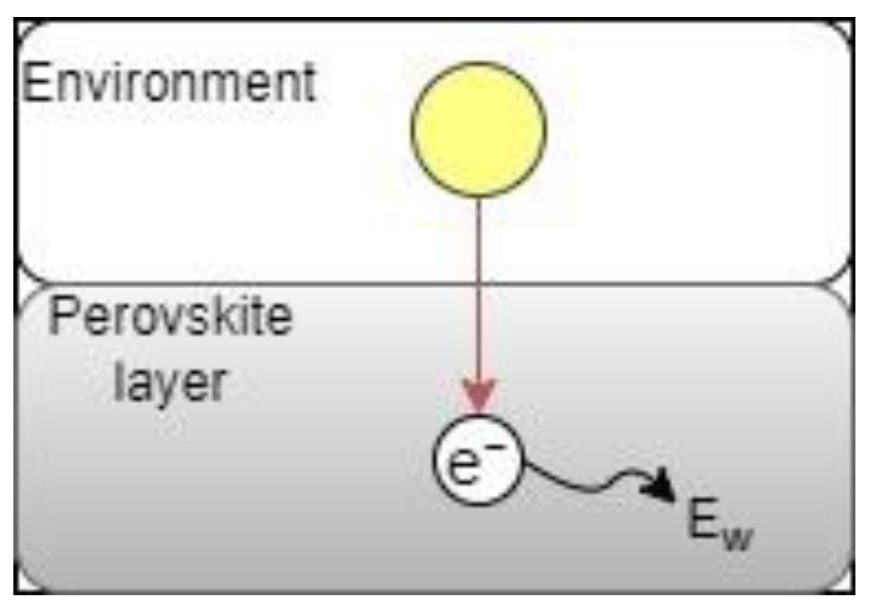
Upon excitation, the energy of a photon can be separated into components within the solar cell that satisfies:
E = E g + E w + E b
where E is the total energy of the photon, E g is the energy required to excite the electron within the material, and E w is the wasted energy. Meanwhile, E b is the binding energy. Note that the E g and E b values vary with different materials. It should also be noted that the bandgap value E g is also temperature-dependent and was modeled accordingly in the study. Details about its dependency are explained in Section 2.5.

2.3.2. Control Case

Figure 2 describes the path that photons take in a normal perovskite solar cell. In this case, as described in Section 2.2.3, photons with enough energy, namely P 2 and P 3 class photons, are able to excite the grounded state electrons within the CH3NH3PbI3 layer. Photons of class P 1 are not absorbed and passed through the CH3NH3PbI3 layer, generating no energy in the process.
The following equations describe the photon excitation process:
S 0 + E P 2 S 1
S 0 + E + E b S 1 + E w
where S0 denotes the ground electron state, and S1 denotes the excited singlet state.
In the control case, the tetracene layer was not included. Thus, photons of class P 3 in this simulation function in the same manner as photons of class P 2 . The amount of wasted energy was calculated using Equation (8):
Σ E w c o n t r o l = λ P 2 4 ϕ E d λ E P 2 ϕ 2 + ϕ 3
The upper and lower bounds of the integration in Equation (8) were determined based on the frequency of the classification cutoff of each type of photon. In the control case, the lower boundary was set to be equal to the frequency corresponding to E P 2 , and the upper boundary was set to be 4 μ m , where the amount of light reaching the solar panel reaches negligible levels.

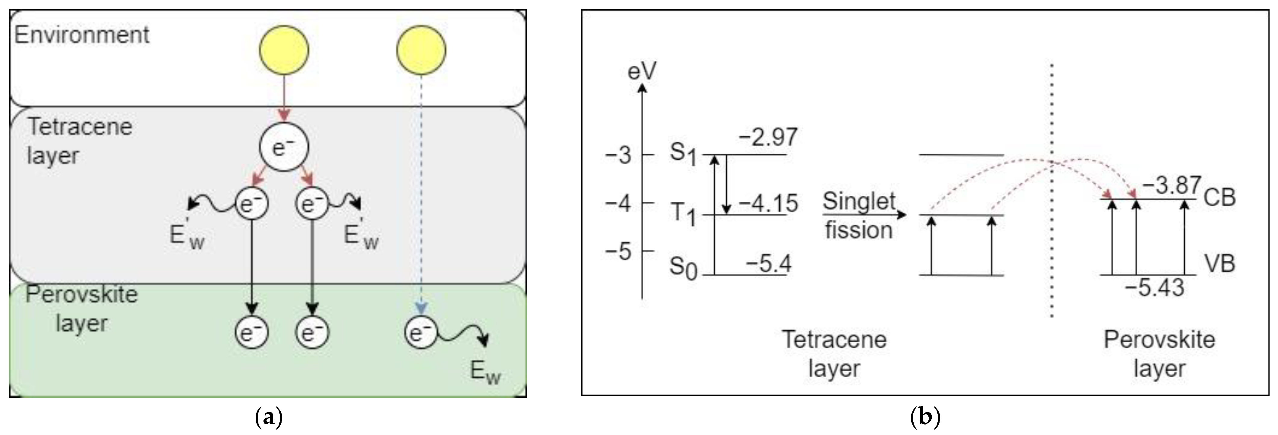
2.3.3. Experimental Case

Figure 3 illustrates the electron excitation process within different layers. Similar to the control case, photons with class P 1 pass through the two layers and are not absorbed. The P 2 photons pass through the tetracene layer effortlessly and reach the CH3NH3PbI3 layer. On the other hand, P 3 photons are able to excite the singlet fission layer and produce two excited state electrons. The pathways for P 2 and P 3 photons are denoted by the dotted and solid lines, respectively.
In the experimental case, the first excitation does not happen in the CH3NH3PbI3 layer but rather in the singlet fission sensitizer layer. In the singlet fission layer, the excited electron shares its leftover energy with its neighboring electron. Overall, the energy process within this case is detailed below:
S 0 + E P 3 2 R 1
S 0 + E + E b 2 R 1 + E W
where S 0 denotes the ground electron state of singlet fission, while R 1 indicates the excited triplet state of the singlet fission layer. E P 3 represents the energy required to excite the singlet fission layer. Lastly, E W represents the wasted energy from the singlet fission layer.
The amount of thermalization loss was calculated in the same manner as the control case:
Σ E w S F = λ P 3 4 ϕ E d λ E P 3 ϕ 3
In the simulation, the tetracene layer was simulated to absorb all photons that have energy at least equal to the energy level E P 3 , the lower bound was set to be the frequency corresponding to E P 3 , and the upper bound was 4 μ m .
The CH3NH3PbI3 layer in this case was modeled to only receive the photons of class P 2 . In this scenario, the amount of wasted energy in the CH3NH3PbI3 layer was calculated using Equation (12):
Σ E w P = λ P 2 λ P 3 ϕ E d λ E P 2 ϕ 2
The lower bound in this case was set to be the frequency corresponding to E P 2 , and the upper bound was set to be the frequency corresponding to E P 3 .
The total amount of thermalization loss within the experimental case is the sum of the two previous losses in Equations (11) and (12):
Σ E w S F = Σ E w T + Σ E w P

2.4. Modeling of Heat Transfer

In order to evaluate the effect of singlet fission on the heating of the solar cell, a method to evaluate the solar cell’s temperature with respect to time is needed. Here, we chose to calculate the temperature change based on two modes of heating: heating due to photon energy thermalization loss and the conduction heat transfer between layers. We imposed a natural restriction: the cutoff temperature of the solar cell should be equal to 65 °C. This restriction was made to reflect how heated the solar panel could be in summer. The effectiveness of the singlet fission mechanism was evaluated based on how fast the temperature rose with respect to time between the two cases considered in this study.

2.4.1. Heating Due to Photon Energy

As emphasized in previous sections, temperature plays a crucial role in this model. Formula (14) was used to describe the change of temperature based on the wasted energy calculated in Section 2.3.2 and Section 2.3.3:
Δ T p = Σ E w m β
where Σ E w is the wasted energy; m and β indicate the mass and specific heat of the material. Lastly, Δ T p represents the change in temperature due to photon energy.
The mass of the material is modeled as a constant throughout the simulation and was calculated using the parameters of a hypothetical solar panel size of 1 m by 1 m.
In this study, to preserve its simplicity, other heat dissipation mechanisms, such as conduction with other layers of the solar cell, the convection heat transfer between the glass to the environment, etc., were ignored. However, by neglecting them, if the thicknesses of the perovskite and tetracene remain a realistic value, the temperature would increase dramatically fast. To circumvent this issue, a modifier was applied to Equations (8), (11), and (12). This modifier reflects the fraction of heat flux the solar layer receives after subtracting the amount of heat lost to conduction toward other layers within the cell. The value for the modifier was found by following the work of Lupez-Valo et al. (2021) [53] and was found to be in the order of 10−10.
The bulk densities of CH3NH3PbI3 and tetracene were 4.2864 g/cm3 [54] and 1.2 g/cm3 [55], respectively.
Normally, the specific heat symbol is c, but in this work, to avoid confusion with the speed of light, it was changed and denoted as β instead.
The specific heats of tetracene and CH3NH3PbI3 were based on the following literature [56,57] and were found to be 1585 (J·kg−1K−1) for tetracene and 311 (J·kg−1K−1) for CH3NH3PbI3.

2.4.2. Heating Due to Conduction Heat Transfer

Conduction is the main heat transfer mechanism between layers within the solar cell. The conduction heat transfer of materials was calculated using Equation (15):
Q C = k A Δ T c L 2
where Q C is the amount of heat transferred per unit time; k represents the thermal conductivity of material; A is the area of contact; Δ T c denotes the change of temperature due to conduction heat transfer; and L characterizes the thickness of the material.
Setting the boundary condition for the two contact surfaces, we obtained:
Q c 1 = 2 k 1 A 1 Δ T c 1 L 1 = 2 k 2 A 2 Δ T c 2 L 2 = Q c 2
Here, since the physical thermal expansion of the material is ignored, A 1 = A 2 . Deriving Equation (16) further, we obtained:
k 1 L 1 T 1 T = k 2 L 2 T T 2
Rearranging Equation (17), we obtained:
T = k 1 L 1 T 1 + k 2 L 2 T 2 k 1 L 1 + k 2 L 2
The conduction process is due to the temperature mismatch between layers of materials. As a result, the heat transfer process only happens after the heating process caused by photon absorption. Therefore, the initial temperature, T1, and T2 were set based on the first calculation of Equation (14).
After the evaluation of the two heat transfer processes, the next increment of photon absorption was calculated.
The thermal conductivities of tetracene and CH3NH3PbI3 were based on the following literature [58,59] and were found to be 0.16 (W/Km) for tetracene and 0.3 (W/Km) for CH3NH3PbI3.

2.5. Modeling of the Bandgap

As the temperature changes, the bandgap of CH3NH3PbI3 also changes accordingly. This change affects the criteria for the classification of photons in Section 2.3 and, subsequently, Equations (8)–(12). The change in bandgap is due to two factors: thermal expansion and electron-phonon interaction. These factors, as well as how to derive them, were summed up by Francisco-López et al. in the following equations [47]:
d E g d T = d E g d T T E + d E g d T E P
where d E g d T is the change of bandgap with respect to temperature. d E g d T T E and d E g d T E P represent the change of bandgap due to thermal expansion and electron-phonon interactions, respectively.

2.5.1. Change of Bandgap Due to Thermal Expansion

The change of bandgap due to thermal expansion is because of the contraction of the lattice with the decreasing temperature and was calculated by Equation (20):
d E g d T T E = α V B 0 d E g d P
where d E g d T T E denotes the change of bandgap due to thermal expansion. α V is the volumetric expansion coefficient, while B 0 represents the bulk modulus. Meanwhile, d E g d P signifies the change of bandgap with respect to pressure. The values for these parameters were summarized by Francisco-López et al. to be αV = 1.57 × 10⁻⁴ K−1; B0 = 18.8 Gpa; and d E g d P = −50 m e V G P a .

2.5.2. Change of Bandgap Due to Electron-Phonon Interactions

The change of bandgap due to electron-phonon expansion includes the Debye–Waller and self-energy corrections and was calculated by:
d E g d T E P = A e f f 4 T ħ ω eff k B T 1 s i n h 2 ħ ω eff 2 k B T
where d E g d T E P is the change of bandgap due to electron-phonon interactions; A e f f represents the electron-phonon coupling constant; ħ ω e f f denotes the average phonon frequency; and k B is the Boltzmann constant. The values for these parameters once again were presented by Francisco-López et al. to be A e f f = 8.09 meV and ħ ω eff = 5.87 meV.
After calculating the resulting bandgap, Section 2, Section 3, Section 4, Section 5 were repeated with the updated values to evaluate the next time step.

3. Model Validation and Calibration

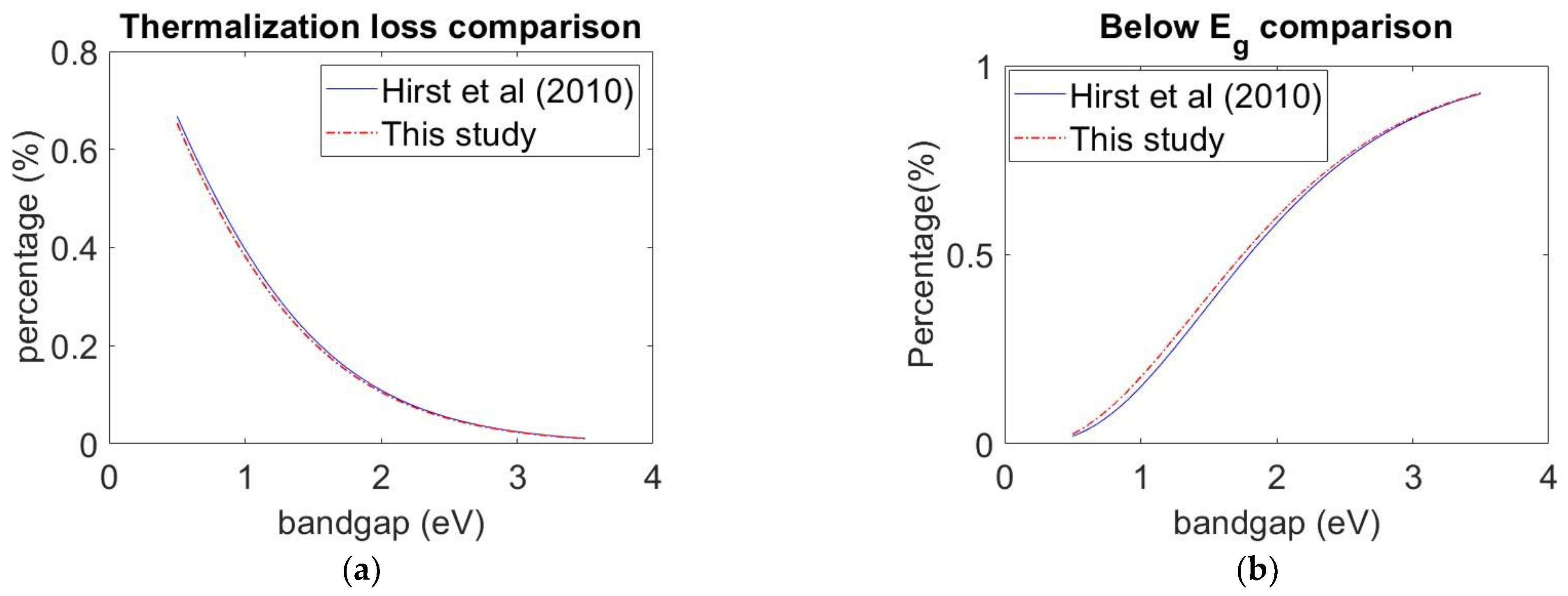
3.1. Model Validation

To test the validity of the model, two sets of data were employed. The first set of data follows the work of Hirst et al. (2010) [60], while the second was generated in this study. The reason Hirst’s study was chosen is because their work provided us with all the necessary data while remaining straightforward and easy for us to reproduce. Their work also provided the best fit for our data and generally agreed with many other sources, such as Heidarzadeh et al. (2020) [27] and Da et al. (2018) [27]. The fraction of loss due to the non-absorption of below-bandgap photons and thermalization were calculated in two studies were compared. The following equations were used to calculate the two variables in this study:
% E b e l o w = 0.2 λ P ϕ λ E λ d λ 0.2 4 ϕ λ E λ d λ
% E w = Σ E w 0.2 4 ϕ λ E λ d λ
The Σ E w value in Equation (22) follows Equation (8) closely, only varying in the λ P value. Equations (21) and (22) were then tested with different bandgap values by varying λ P and, subsequentially, Σ E w to test its consistency with other literature.

3.2. Model Validation Result

Figure 4 shows the results of the comparison. It is clear that our method closely follows Hirst et al. (2010)’s work. These results also agree with other literature [27,61]. Table 1 shows the maximum errors, as well as the bandgap value of said errors between the two sets of data. Meanwhile, Table 2 summarizes the parameters used in this study for the perovskite and tetracene layers.

3.3. Model Calibration

As mentioned in Section 2.4.1, with the absence of other heat-dissipating processes, if the thickness of the perovskite and tetracene layer were to be kept at realistic values, the temperature would have to rise extremely fast to yield any meaningful result. Therefore, the thickness of the two layers were set extremely high to compensate for this issue. This would be equivalent to setting the effective thickness required by a layer to have the same properties as a normal solar cell. After calibrating, the reference values were set to be L p e v = L t e t = 400 × 10 9 m . This reflects the average thickness of the perovskite layer in a conventional solar cell. These values will also be varied to test the impact of the thickness of each layer on the effectiveness of singlet fission.
In a conventional solar cell, in order for the perovskite layer to function properly, many heat dissipation mechanisms are employed. This includes, but is not limited to, adding insulation layers, which improves the conduction between layers. In fact, heat dissipation mechanisms help reduce the heat produced by the perovskite layer to an almost negligible level. Without those mechanisms, the perovskite layer would have to compensate by catastrophically increasing its thickness. Therefore, in the absence of these heat dissipation effects, a modifier should be applied. In this study, we followed the work of Lupez-Valo et al. (2021) [53]. In their work, the heat flux produced by the perovskite layer was offset by the conduction toward the front and back glass of the solar panel. Following their work, we applied the modifier of around 10−10, representing the fraction of heat flux received by the perovskite layer after the conduction process.
In this study, four tests were performed. The first test was used to examine the initial effect of the tetracene layer on the de-heating of the perovskite layer. The value for the perovskite layer was chosen to be 400 × 10 9   m or 400   nm . This reflects the average thickness of the perovskite layer in a conventional solar cell. The thickness of the tetracene layer was arbitrarily chosen to be the same as the thickness of the perovskite layer, i.e., 400   nm . The optimum value for the tetracene thickness will be examined and discussed in a later test.
In the second test, different thicknesses of the two layers were examined. This test served to establish the trend when different thicknesses of the two layers were applied. The reference values were chosen arbitrarily and were chosen to be twice the value in the reference case. The test was compared to the base condition to establish said trends. Furthermore, an arbitrary small value of L t e t was chosen to further strengthen our trend. The value chosen was 10−8.
In the third test, the optimum value for the tetracene thickness for commercial perovskite solar cell was investigated. The test was conducted by setting different values for L t e t and examined the temperature of the perovskite layer after an instant of time.
Finally, a different value of solar radiation was chosen to test the effectiveness of tetracene under different conditions. For this test, the solar constant G S C was changed to be 800 W/m2. This value was chosen to reflect the nominal operating cell temperature (NOCT) listed condition.

4. Results and Discussion

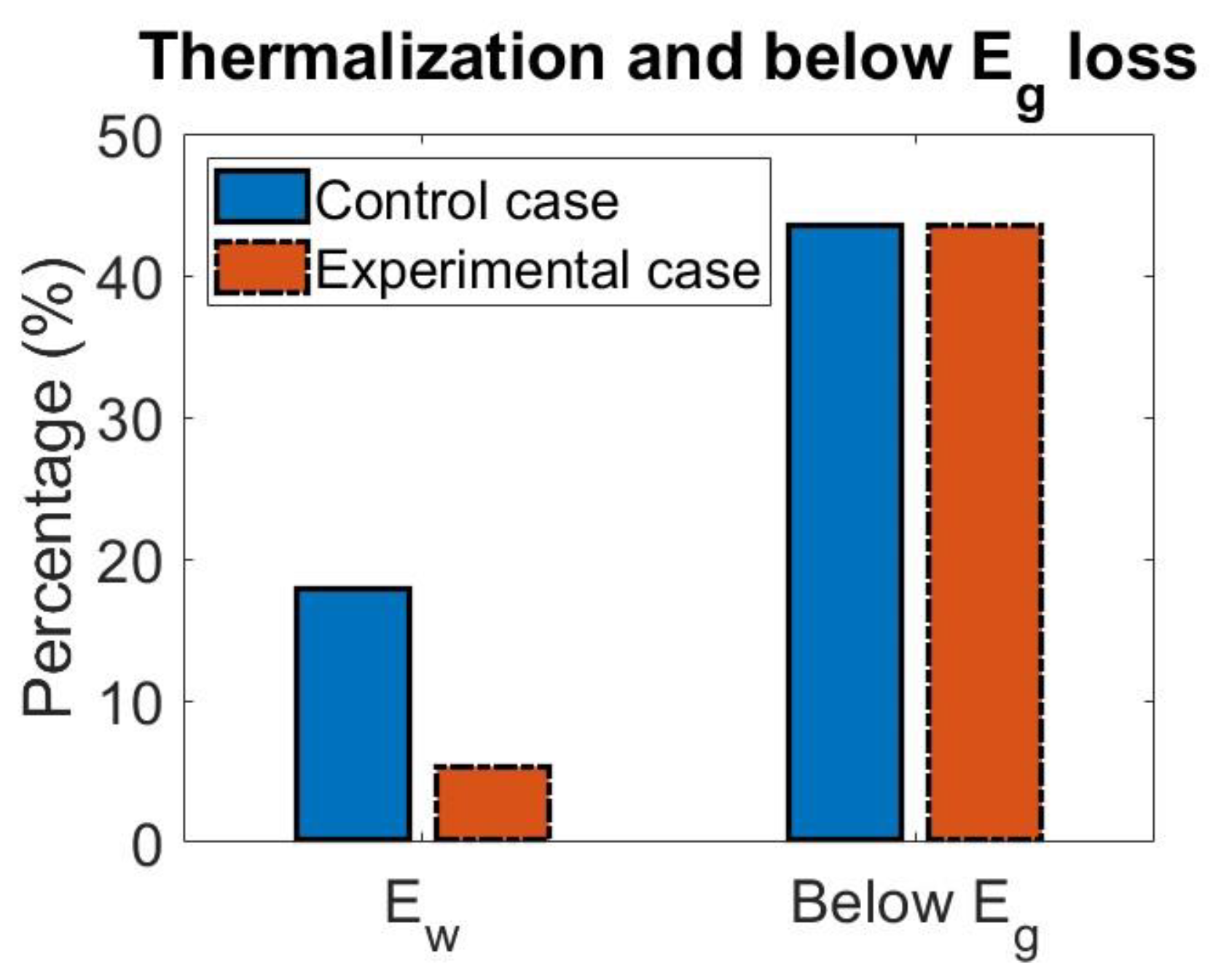
4.1. Effect of Singlet Fission on Losses

Figure 5 and Table 3 display the percentage of loss due to thermalization and below-bandgap photons in the perovskite layer in the control and the experimental case. It is easy to see that adding a layer of tetracene into the system dramatically decreases the thermalization loss of the perovskite layer. More specifically, with the same amount of input energy, the percentage loss due to thermalization drops to 5.36%, compared to 17.95% in the control case. Moreover, since the difference in thermalization loss between the two cases was converted into triplet state excitons by singlet fission, the reduced amount can contribute to the efficiency of the solar cell. Meanwhile, the tetracene layer did not contribute to the mitigation of below-bandgap photons. Therefore, the percentage loss remains identical to the control case, at 43.55%. This makes sense, given that singlet fission only occurs when the photon energy is higher than the bandgap of the tetracene layer, which is higher than the bandgap of perovskite. With these data, we could conclude that coupling a tetracene layer to the perovskite solar cell system is able to convert thermalization loss into useable electrons, while not increasing the Eg loss. Therefore, we could draw the inference that the tetracene layer could potentially increase the efficiency of the solar cell system.
As mentioned in earlier sections, the mismatch in bandgaps of the two materials and their effect on singlet fission is under debate and is neglected here, although it could be the focus of a future study.

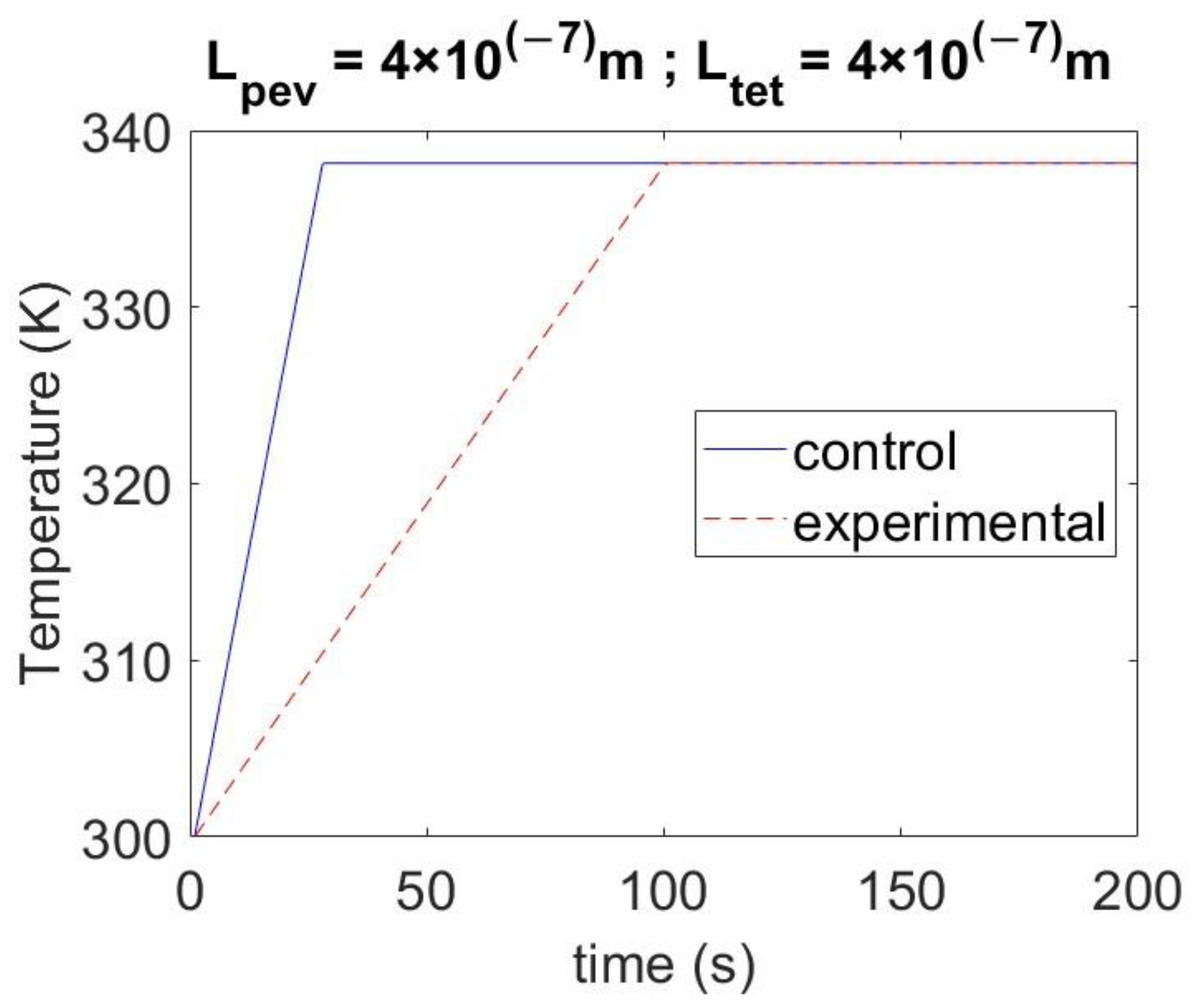
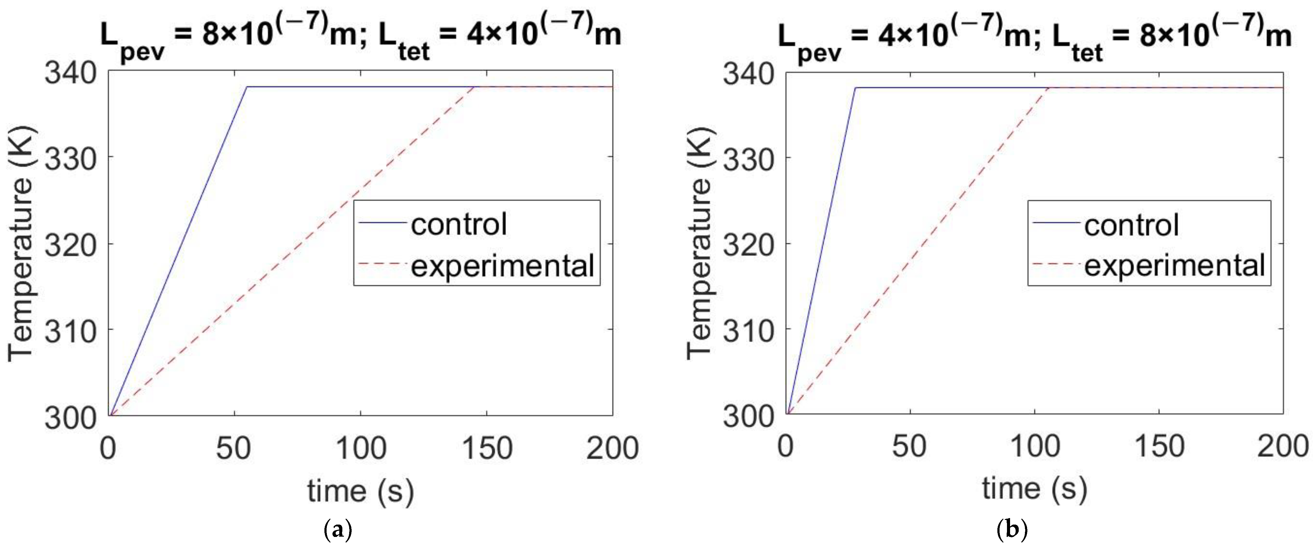
4.2. Effect of Singlet Fission on the Heating of the Perovskite Layer

Figure 6 shows the difference in the heating time of the perovskite layer between the two cases simulated in this study. As the graph shows, coupling a tetracene layer on the perovskite layer dramatically increases the time the perovskite layer needs to increase to the designated cutoff temperature. More specifically, in the control case, the perovskite layer achieved the cutoff temperature at 22 s. Meanwhile, in the experimental case, the perovskite layer reached the cutoff temperature at 100 s.
It should be noted that in our study, we imposed a natural restriction on the cutoff temperature. Without this restriction, the temperature in the experimental case would continue to increase, while the control case would stabilize after some time. This is due to the fact that the bandgap of the tetracene was set to be constant. This means that no matter how the material is heated, it will continue to absorb photons.

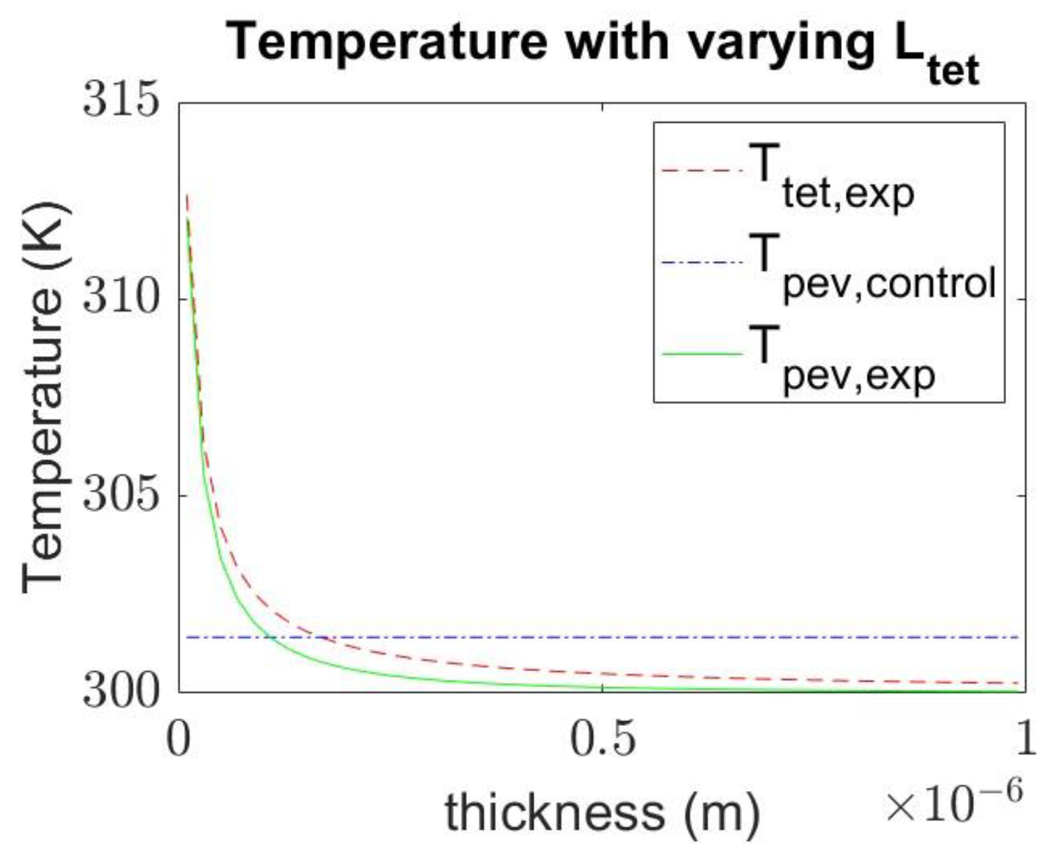
4.3. Effect of Varying the Thickness of Materials on Temperature

The thickness of the layers plays an important role in the temperature of the layers. If the thickness of the tetracene layer was set to be too low, the heating of the tetracene layer would be quicker than the perovskite layer. This could potentially cause the perovskite layer to degrade even faster due to the heat flux coming from the tetracene layer.
Next, by examining Figure 7a, it is clear to see that increasing the thickness of the perovskite layer results in a slower slope in both cases. This result is reasonable, given that the perovskite layer exists in both cases. Moreover, comparing this figure with Figure 6, we can see that the change in thickness of the perovskite layer benefits the experimental case more. In the control case, the time to reach the cutoff temperature is about 50 s, as opposed to 22 s in the base condition. However, in the experimental case, the change is around 50 s compared to the base condition. However, given that one of the main advantages of perovskite solar cells is its thin-film nature, increasing its thickness is not always the ideal solution.
On the other hand, Figure 7b suggests that increasing the thickness of the tetracene layer benefits the experimental case exclusively. This is due to the fact that the tetracene layer only exists in the experimental case. However, the change is much smaller compared to increasing the perovskite layer, with the difference in time only being about 2 s. From the data from Figure 7b, we could draw the conclusion that if the tetracene layer is thin enough, the experimental system could be detrimental to the perovskite layer instead of helping it. Figure 8 shows the case in such a scenario, where the tetracene’s thickness was set to be much lower than the thickness of the perovskite layer. In Figure 8, we can clearly see that the perovskite layer in the experimental case reaches the cutoff temperature almost instantly, while the control case remains unchanged compared to the base conditions, further confirming our trend.
Figure 9 displays the temperature after the first timestep as a function of the thickness of the tetracene layer. The perovskite thickness was set as 400 × 10 9 m in this figure. As the figure shows, the perovskite layer in the control case does not change its temperature value with varying thicknesses. This makes sense since the tetracene layer is not involved in the control case. Meanwhile, we can see that with the tetracene thickness being close to zero, the temperatures of both the tetracene and perovskite layer in the experimental case are higher than the value in the control case. The reason for such results is due to the heating of the tetracene layer. In the experimental case, the temperature in the tetracene layer rises faster than in the perovskite layer. In other words, heat transfer is a detriment to the perovskite layer if singlet fission is implemented. In the case of thin tetracene layers, the cost of heat transfer outweighs the benefits of thermalization reduction. However, in the case of thick tetracene, such a cost is mitigated, leading to a reduction in the temperature of the perovskite layer.
Figure 9 also confirms that increasing the thickness of the tetracene layer is beneficial to the de-heating process in the perovskite layer. However, once again, with the strength of perovskite solar cells being their thin-film nature, the solution is not as straightforward as just increasing the thickness of the layer. In order to design a solar cell utilizing singlet fission while retaining its thin-film nature, the thickness of layers should be taken into consideration. Using data from Figure 9, we can conclude that the optimum value for the tetracene layer is around 1.75 × 10 8 m.

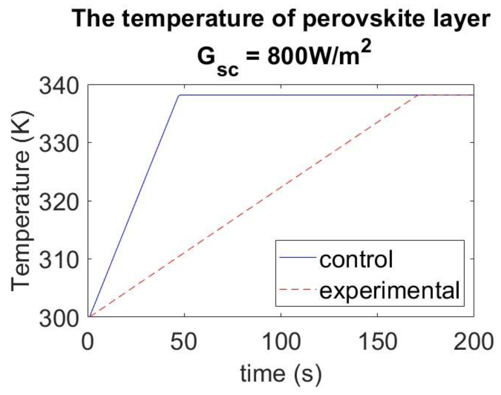
4.4. Effect of Tetracene Layer under Different Solar Radiation Conditions

Figure 10 displays the temperature of the solar cell when the solar radiation is 800 W/m2. As expected, with lower solar radiation, the time to reach the cutoff temperature for both the control and experimental case increases. However, there is a significant difference in the change between the two cases. In the control case, the time to reach the cutoff temperature is around 50 s, as opposed to 22 s in the base conditions. In contrast, in the experimental case, the time to reach the cutoff temperature is significantly longer at around 170 s, as opposed to 100 s in the base conditions. From Figure 10’s data, we can conclude that the tetracene layer performs even better in weak solar radiation setting.

5. Conclusions

This study presented a model investigating the amount of loss by a perovskite solar layer with and without singlet fission. This model closely follows other similar literature while remaining simple and efficient. We also developed a simulation to show the rate of increasing temperature in the perovskite layer. Two simulations were performed to compare the rate of increasing temperature in the control setting and the experimental setting. Our results show that coupling singlet fission provided a slower slope compared to the control case. However, the effectiveness depends on the thickness of the tetracene layer. Through documenting the thermalization and loss of below-bandgap photons of the control and experimental case, our study shows that coupling a layer of tetracene provides a potential benefit to the perovskite solar cell. Our study also shows that coupling an appropriate layer of tetracene will slow the temperature rise in the perovskite layer, providing time for other heat dissipation modes to take effect and effectively reducing the operating temperature of the solar cell. In the long run, this will help the long-term health of the solar cell. This paper also highlights a meaningful parameter when designing a tandem solar cell utilizing singlet fission mechanisms. Moving forward, other effects the tetracene may have on the solar cell, such as moisture, UV light, etc., could be the focus of our future studies. On the other hand, future studies are also needed to include different modes of heat dissipation, such as convection and radiation heat transfer from other layers of the solar cell, to better reflect reality.

Author Contributions

Conceptualization, T.N.L. and L.L.; methodology, T.N.L. and L.L.; software, T.N.L. and L.L.; validation, T.N.L. and L.L.; formal analysis, T.N.L. and L.L.; investigation, T.N.L. and L.L.; resources, T.N.L. and L.L.; data curation, T.N.L. and L.L.; writing—original draft preparation, T.N.L. and L.L.; writing—review and editing, T.N.L. and L.L.; visualization, T.N.L. and L.L.; supervision, L.L.; project administration, L.L.; funding acquisition, L.L. All authors have read and agreed to the published version of the manuscript.

Funding

This research was funded by the Kansas Soybean Commission, KU ASCEND Award, KU RISe Award, KU Research GO awards, and KU General Research Funds.

Data Availability Statement

The data presented in this study are openly available in Zenodo at https://doi.org/10.5281/zenodo.7613046 (accessed on 6 February 2023), and available upon request.

Acknowledgments

The author would like to thank the support from the Kansas Soybean Commission, KU ASCEND Award, KU RISe Award, KU Research GO awards, and KU General Research Funds.

Conflicts of Interest

The authors declare no conflict of interest.

Abbreviations

SymbolDefinition
G 0 Solar spectral flux density
λ Wavelength of light
G S C Solar constant
a Modifier parameter
E Energy of photons
h Planck’s constant
c Speed of light
ϕ Number of photons
ϕ 1 Number of electrons of class P1
ϕ 2 Number of electrons of class P2
ϕ 3 Number of electrons of class P3
E g Band gap of the material
E P 2 The energy level of photon class P2
E P 3 The energy level of photon class P3
E w Thermalization energy loss
S 0 Grounded electron state of perovskite
S 1 Excited singlet electron state of perovskite
E w c o n t r o l Wasted energy in the control case
S 0 Grounded electron state of tetracene
R 1 Triplet electron state of tetracene
E w Wasted energy in the tetracene layer in the experimental case
E w S F Thermalization energy loss of tetracene layer in experimental case
E w P Thermalization energy loss of perovskite layer in experimental case
Δ T p Change of temperature due to photon energy
m Mass of the layer
β Specific heat of the material
Q C Heating due to heat transfer
Δ T c Temperature changes due to heat transfer
k Thermal conductivity of the material
A Area of contact
L Thickness of material
T Temperature
d E g d T Change of bandgap with respect to temperature
d E g d T T E Change of bandgap due to thermal expansion
d E g d T E P Change of bandgap due to electron-phonon interactions
α V Volumetric expansion coefficient
B 0 Bulk modulus
d E g d P Change of bandgap with respect to pressure
A e f f Electron-phonon coupling constant
ħ ω eff Average phonon frequency
k B Boltzmann constant
% E b e l o w Fraction of loss due to below-bandgap photons
% E w Fraction of loss due to thermalization

References

  1. Porté-Agel, F.; Bastankhah, M.; Shamsoddin, S. Wind-Turbine and Wind-Farm Flows: A Review. Bound. Layer Meteorol. 2020, 174, 1–59. [Google Scholar] [CrossRef] [Green Version]
  2. Wang, D.-Z.; Liu, W.-D.; Li, M.; Yin, L.-C.; Gao, H.; Sun, Q.; Wu, H.; Wang, Y.; Shi, X.-L.; Yang, X.; et al. Simultaneously achieving high ZT and mechanical hardness in highly alloyed GeTe with symmetric nanodomains. Chem. Eng. J. 2022, 441, 136131. [Google Scholar] [CrossRef]
  3. Wang, D.-Z.; Liu, W.-D.; Li, M.; Zheng, K.; Hu, H.; Yin, L.-C.; Wang, Y.; Zhu, H.; Shi, X.-L.; Yang, X.; et al. Hierarchical Architectural Structures Induce High Performance in n-Type GeTe-Based Thermoelectrics. Adv. Funct. Mater. 2023, 2213040. [Google Scholar] [CrossRef]
  4. Duan, J.; Xu, H.; Sha, W.E.I.; Zhao, Y.; Wang, Y.; Yang, X.; Tang, Q. Inorganic perovskite solar cells: An emerging member of the photovoltaic community. J. Mater. Chem. A 2019, 7, 21036–21068. [Google Scholar] [CrossRef]
  5. Mutalikdesai, A.; Ramasesha, S.K. Emerging solar technologies: Perovskite solar cell. Resonance 2017, 22, 1061–1083. [Google Scholar] [CrossRef]
  6. Park, N.-G. Perovskite solar cells: An emerging photovoltaic technology. Mater. Today 2015, 18, 65–72. [Google Scholar] [CrossRef]
  7. Zhu, Y.; Liu, Y.; Ai, Q.; Gao, G.; Yuan, L.; Fang, Q.; Tian, X.; Zhang, X.; Egap, E.; Ajayan, P.M.; et al. In Situ Synthesis of Lead-Free Halide Perovskite–COF Nanocomposites as Photocatalysts for Photoinduced Polymerization in Both Organic and Aqueous Phases. ACS Mater. Lett. 2022, 4, 464–471. [Google Scholar] [CrossRef]
  8. Zhu, Y.; Liu, Y.; Miller, K.A.; Zhu, H.; Egap, E. Lead Halide Perovskite Nanocrystals as Photocatalysts for PET-RAFT Polymerization under Visible and Near-Infrared Irradiation. ACS Macro Lett. 2020, 9, 725–730. [Google Scholar] [CrossRef] [PubMed]
  9. Xu, Y.-F.; Yang, M.-Z.; Chen, B.-X.; Wang, X.-D.; Chen, H.-Y.; Kuang, D.-B.; Su, C.-Y. A CsPbBr3 Perovskite Quantum Dot/Graphene Oxide Composite for Photocatalytic CO2 Reduction. J. Am. Chem. Soc. 2017, 139, 5660–5663. [Google Scholar] [CrossRef] [PubMed]
  10. Wei, K.; Liang, B.; Sun, C.; Jiang, Y.; Yuan, M. Metal Halide Perovskites for Red-Emission Light-Emitting Diodes. Small Struct. 2022, 3, 2200063. [Google Scholar] [CrossRef]
  11. Yang, W.S.; Noh, J.H.; Jeon, N.J.; Kim, Y.C.; Ryu, S.; Seo, J.; Seok, S.I. High-performance photovoltaic perovskite layers fabricated through intramolecular exchange. Science 2015, 348, 1234–1237. [Google Scholar] [CrossRef] [PubMed]
  12. Shockley, W.; Queisser, H.J. Detailed Balance Limit of Efficiency of p-n Junction Solar Cells. J. Appl. Phys. 1961, 32, 510–519. [Google Scholar] [CrossRef]
  13. Andreani, L.C.; Bozzola, A.; Kowalczewski, P.; Liscidini, M.; Redorici, L. Silicon solar cells: Toward the efficiency limits. Adv. Phys. X 2018, 4, 1548305. [Google Scholar] [CrossRef] [Green Version]
  14. Perovskite on Silicon Tandem Solar Cell Technology | Oxford PV. Oxfordpv. Retrieved 16 May 16 2021. Available online: https://www.oxfordpv.com/perovskite-silicon-tandem (accessed on 6 February 2023).
  15. Čulík, P.; Brooks, K.; Momblona, C.; Adams, M.; Kinge, S.; Maréchal, F.; Dyson, P.J.; Nazeeruddin, M.K. Design and Cost Analysis of 100 MW Perovskite Solar Panel Manufacturing Process in Different Locations. ACS Energy Lett. 2022, 7, 3039–3044. [Google Scholar] [CrossRef]
  16. Wei, Z.; Chen, H.; Yan, K.; Yang, S. Inkjet Printing and Instant Chemical Transformation of a CH3NH3PbI3/Nanocarbon Electrode and Interface for Planar Perovskite Solar Cells. Angew. Chem. Int. Ed. 2014, 53, 13239–13243. [Google Scholar] [CrossRef]
  17. Kim, Y.Y.; Yang, T.Y.; Suhonen, R.; Kemppainen, A.; Hwang, K.; Jeon, N.J.; Seo, J. Roll-to-roll gravure-printed flexible perovskite solar cells using eco-friendly antisolvent bathing with wide processing window. Nat. Commun. 2020, 11, 5146. [Google Scholar] [CrossRef]
  18. Ono, L.K.; Qi, Y.; Liu, S. Progress toward Stable Lead Halide Perovskite Solar Cells. Joule 2018, 2, 1961–1990. [Google Scholar] [CrossRef] [Green Version]
  19. Ahmad, Z.; Najeeb, M.A.; Shakoor, R.A.; Alashraf, A.; Al-Muhtaseb, S.A.; Soliman, A.; Nazeeruddin, M.K. Instability in CH3NH3PbI3 perovskite solar cells due to elemental migration and chemical composition changes. Sci. Rep. 2017, 7, 15406. [Google Scholar] [CrossRef] [Green Version]
  20. Wang, D.; Wright, M.; Elumalai, N.K.; Uddin, A. Stability of perovskite solar cells. Sol. Energy Mater. Sol. Cells 2016, 147, 255–275. [Google Scholar] [CrossRef]
  21. Leijtens, T.; Eperon, G.E.; Pathak, S.; Abate, A.; Lee, M.M.; Snaith, H.J. Overcoming ultraviolet light instability of sensitized TiO2 with meso-superstructured organometal tri-halide perovskite solar cells. Nat. Commun. 2013, 4, 2885. [Google Scholar] [CrossRef] [Green Version]
  22. Dualeh, A.; Gao, P.; Seok, S.I.; Nazeeruddin, M.K.; Grätzel, M. Thermal Behavior of Methylammonium Lead-Trihalide Perovskite Photovoltaic Light Harvesters. Chem. Mater. 2014, 26, 6160–6164. [Google Scholar] [CrossRef]
  23. Philippe, B.; Park, B.W.; Lindblad, R.; Oscarsson, J.; Ahmadi, S.; Johansson, E.M.J.; Rensmo, H. Chemical and Electronic Structure Characterization of Lead Halide Perovskites and Stability Behavior under Different Exposures—A Photoelectron Spectroscopy Investigation. Chem. Mater. 2015, 27, 1720–1731. [Google Scholar] [CrossRef]
  24. Mali, S.S.; Shim, C.S.; Hong, C.K. Highly stable and efficient solid-state solar cells based on methylammonium lead bromide (CH3NH3PbBr3) perovskite quantum dots. NPG Asia Mater. 2015, 7, e208. [Google Scholar] [CrossRef] [Green Version]
  25. Singh, A.; Matteocci, F.; Zhu, H.; Rossi, D.; Mejaouri, S.; Cacovich, S.; Auf Der Maur, M.; Sauvage, F.; Gagliardi, A.; Grätzel, M.; et al. Methylamine Gas Treatment Affords Improving Semitransparency, Efficiency, and Stability of CH3NH3PbBr3-Based Perovskite Solar Cells. Sol. RRL 2021, 5, 2100277. [Google Scholar] [CrossRef]
  26. Wang, L.; Yuan, G.D.; Duan, R.F.; Huang, F.; Wei, T.B.; Liu, Z.Q.; Wang, J.X.; Li, J.M. Tunable bandgap in hybrid perovskite CH3NH3Pb(Br3−yXy) single crystals and photodetector applications. AIP Adv. 2016, 6, 045115. [Google Scholar] [CrossRef] [Green Version]
  27. Heidarzadeh, H.; Rostami, A.; Dolatyari, M. Management of losses (thermalization-transmission) in the Si-QDs inside 3C–SiC to design an ultra-high-efficiency solar cell. Mater. Sci. Semicond. Process. 2020, 109, 104936. [Google Scholar] [CrossRef]
  28. Rühle, S. Tabulated values of the Shockley–Queisser limit for single junction solar cells. Sol. Energy 2016, 130, 139–147. [Google Scholar] [CrossRef]
  29. Niu, G.; Li, W.; Li, J.; Liang, X.; Wang, L. Enhancement of thermal stability for perovskite solar cells through cesium doping. RSC Adv. 2017, 7, 17473–17479. [Google Scholar] [CrossRef] [Green Version]
  30. Rolston, N.; Bush, K.A.; Printz, A.D.; Gold-Parker, A.; Ding, Y.; Toney, M.F.; McGehee, M.D.; Dauskardt, R.H. Engineering Stress in Perovskite Solar Cells to Improve Stability. Adv. Energy Mater. 2018, 8, 1802139. [Google Scholar] [CrossRef]
  31. Choi, K.; Lee, J.; Choi, H.; Kim, G.-W.; Kim, H.I.; Park, T. Heat dissipation effects on the stability of planar perovskite solar cells. Energy Environ. Sci. 2020, 13, 5059–5067. [Google Scholar] [CrossRef]
  32. Jiang, Y.; Nielsen, M.P.; Baldacchino, A.J.; Green, M.A.; McCamey, D.R.; Tayebjee, M.J.Y.; Schmidt, T.W.; Ekins-Daukes, N.J. Singlet fission and tandem solar cells reduce thermal degradation and enhance lifespan. Prog. Photovolt. Res. Appl. 2021, 29, 899–906. [Google Scholar] [CrossRef]
  33. Smith, M.B.; Michl, J. Singlet Fission. Chem. Rev. 2010, 110, 6891–6936. [Google Scholar] [CrossRef]
  34. Pazos-Outón, L.M.; Lee, J.M.; Futscher, M.H.; Kirch, A.; Tabachnyk, M.; Friend, R.H.; Ehrler, B. A Silicon–Singlet Fission Tandem Solar Cell Exceeding 100% External Quantum Efficiency with High Spectral Stability. ACS Energy Lett. 2017, 2, 476–480. [Google Scholar] [CrossRef] [Green Version]
  35. United States Department of Energy Basic Energy Sciences Division. Proceedings of the 27th DOE Solar Photochemistry Research Conference, Airlie Conference Center, Warrenton, VA, USA, 6–9 June 2004; United States Department of Energy Basic Energy Sciences Division: Washington, DC, USA, 2004.
  36. MacQueen, R.W.; Liebhaber, M.; Niederhausen, J.; Mews, M.; Gersmann, C.; Jäckle, S.; Jäger, K.; Tayebjee, M.J.Y.; Schmidt, T.W.; Rech, B.; et al. Crystalline silicon solar cells with tetracene interlayers: The path to silicon-singlet fission heterojunction devices. Mater. Horiz. 2018, 5, 1065–1075. [Google Scholar] [CrossRef] [Green Version]
  37. Baldacchino, A.J.; Collins, M.I.; Nielsen, M.P.; Schmidt, T.W.; McCamey, D.R.; Tayebjee, M.J.Y. Singlet fission photovoltaics: Progress and promising pathways. Chem. Phys. Rev. 2022, 3, 021304. [Google Scholar] [CrossRef]
  38. Chan, W.-L.; Ligges, M.; Zhu, X.Y. The energy barrier in singlet fission can be overcome through coherent coupling and entropic gain. Nat. Chem. 2012, 4, 840–845. [Google Scholar] [CrossRef] [PubMed]
  39. Paci, I.; Johnson, J.C.; Chen, X.; Rana, G.; Popović, D.; David, D.E.; Nozik, A.J.; Ratner, M.A.; Michl, J. Singlet Fission for Dye-Sensitized Solar Cells:  Can a Suitable Sensitizer Be Found? J. Am. Chem. Soc. 2006, 128, 16546–16553. [Google Scholar] [CrossRef] [PubMed]
  40. Thomson, S.A.J.; Niklas, J.; Mardis, K.L.; Mallares, C.; Samuel, I.D.W.; Poluektov, O.G. Charge Separation and Triplet Exciton Formation Pathways in Small-Molecule Solar Cells as Studied by Time-Resolved EPR Spectroscopy. J. Phys. Chem. C 2017, 121, 22707–22719. [Google Scholar] [CrossRef] [Green Version]
  41. D’Innocenzo, V.; Grancini, G.; Alcocer, M.; Kandada, A.R.S.; Stranks, S.D.; Lee, M.M.; Lanzani, G.; Snaith, H.J.; Petrozza, A. Excitons versus free charges in organo-lead tri-halide perovskites. Nat. Commun. 2014, 5, 3586. [Google Scholar] [CrossRef] [Green Version]
  42. Asghar, M.I.; Zhang, J.; Wang, H.; Lund, P.D. Device stability of perovskite solar cells—A review. Renew. Sustain. Energy Rev. 2017, 77, 131–146. [Google Scholar] [CrossRef] [Green Version]
  43. Zhao, X.; Park, N.-G. Stability Issues on Perovskite Solar Cells. Photonics 2015, 2, 1139–1151. [Google Scholar] [CrossRef] [Green Version]
  44. Xia, J.; Sanders, S.N.; Cheng, W.; Low, J.Z.; Liu, J.; Campos, L.M.; Sun, T. Singlet Fission: Progress and Prospects in Solar Cells. Adv. Mater. 2017, 29, 1601652. [Google Scholar] [CrossRef]
  45. Wu, T.C.; Thompson, N.J.; Congreve, D.N.; Hontz, E.; Yost, S.R.; Van Voorhis, T.; Baldo, M.A. Singlet fission efficiency in tetracene-based organic solar cells. Appl. Phys. Lett. 2014, 104, 193901. [Google Scholar] [CrossRef] [Green Version]
  46. Paulescu, M.; Schlett, Z. A simplified but accurate spectral solar irradiance model. Theor. Appl. Climatol. 2003, 75, 203–212. [Google Scholar] [CrossRef]
  47. Francisco-López, A.; Charles, B.; Weber, O.J.; Alonso, M.I.; Garriga, M.; Campoy-Quiles, M.; Weller, M.T.; Goñi, A.R. Equal Footing of Thermal Expansion and Electron–Phonon Interaction in the Temperature Dependence of Lead Halide Perovskite Band Gaps. J. Phys. Chem. Lett. 2019, 10, 2971–2977. [Google Scholar] [CrossRef]
  48. Qin, P.; Tanaka, S.; Ito, S.; Tetreault, N.; Manabe, K.; Nishino, H.; Nazeeruddin, M.K.; Grätzel, M. Inorganic hole conductor-based lead halide perovskite solar cells with 12.4% conversion efficiency. Nat. Commun. 2014, 5, 3834. [Google Scholar] [CrossRef] [PubMed] [Green Version]
  49. Nakka, L.; Cheng, Y.; Aberle, A.G.; Lin, F. Analytical Review of Spiro-OMeTAD Hole Transport Materials: Paths Toward Stable and Efficient Perovskite Solar Cells. Adv. Energy Sustain. Res. 2022, 3, 2200045. [Google Scholar] [CrossRef]
  50. de Sabata, C.; Borneas, M.; Rothenstein, B.; Munteanu, A. Bazele Fizice Ale Conversiei Energiei Solare; Facla: Timisoara, Romania, 1982; pp. 28–29. [Google Scholar]
  51. Şahin, A.D.; Şen, Z. Statistical analysis of the Angström formula coefficients and application for Turkey. Fuel Energy Abstr. 1998, 39, 125. [Google Scholar] [CrossRef]
  52. Kulkarni, S.A.; Baikie, T.; Boix, P.P.; Yantara, N.; Mathews, N.; Mhaisalkar, S. Band-gap tuning of lead halide perovskites using a sequential deposition process. J. Mater. Chem. A 2014, 2, 9221–9225. [Google Scholar] [CrossRef] [Green Version]
  53. Lopez-Varo, P.; Amara, M.; Cacovich, S.; Julien, A.; Yaïche, A.; Jouhari, M.; Rousset, J.; Schulz, P.; Guillemoles, J.-F.; Puel, J.-B. Dynamic temperature effects in perovskite solar cells and energy yield. Sustain. Energy Fuels 2021, 5, 5523–5534. [Google Scholar] [CrossRef]
  54. Starr, D.E.; Sadoughi, G.; Handick, E.; Wilks, R.G.; Alsmeier, J.H.; Köhler, L.; Gorgoi, M.; Snaith, H.J.; Bär, M. Direct observation of an inhomogeneous chlorine distribution in CH3NH3PbI3−xClx layers: Surface depletion and interface enrichment. Energy Environ. Sci. 2015, 8, 1609–1615. [Google Scholar] [CrossRef]
  55. Tetracene. ChemSpider. Retrieved 11 November 11 2022. Available online: http://www.chemspider.com/Chemical-Structure.6813.html (accessed on 6 February 2023).
  56. Haeger, T.; Heiderhoff, R.; Riedl, T. Thermal properties of metal-halide perovskites. J. Mater. Chem. C 2020, 8, 14289–14311. [Google Scholar] [CrossRef]
  57. Tabor, D Mechanical Properties of Energetic Materials. Publication No. ADA039600. Physics & Chemistry of Solids Cavandish Labatory. 1977. Available online: https://apps.dtic.mil/sti/pdfs/ADA039600.pdf (accessed on 6 February 2023).
  58. Pisoni, A.; Jaćimović, J.; Barišić, O.S.; Spina, M.; Gaál, R.; Forró, L.; Horváth, E. Ultra-Low Thermal Conductivity in Organic–Inorganic Hybrid Perovskite CH3NH3PbI3. J. Phys. Chem. Lett. 2014, 5, 2488–2492. [Google Scholar] [CrossRef] [Green Version]
  59. Tabor, D.; Field, J.E.; Chaudri, M.M.; Hauser, H.M.; Patel, R.G.; Cambridge Univ (United Kingdom) Cavendish Lab. Mechanical Properties of Energetic Materials. DTIC. Retrieved 31 October 2022. Available online: https://apps.dtic.mil/sti/citations/ADA039600 (accessed on 6 February 2023).
  60. Hirst, L.C.; Ekins-Daukes, N.J. Fundamental losses in solar cells. Prog. Photovolt. Res. Appl. 2011, 19, 286–293. [Google Scholar] [CrossRef]
  61. Da, Y.; Xuan, Y.; Li, Q. Quantifying energy losses in planar perovskite solar cells. Sol. Energy Mater. Sol. Cells 2018, 174, 206–213. [Google Scholar] [CrossRef]
  62. Tanaka, K.; Takahashi, T.; Ban, T.; Kondo, T.; Uchida, K.; Miura, N. Comparative study on the excitons in lead-halide-based perovskite-type crystals CH3NH3PbBr3 CH3NH3PbI3. Solid State Commun. 2003, 127, 619–623. [Google Scholar] [CrossRef]
Figure 1. (a) The configuration for the control case. (b) The configuration for the experimental case. (c) Band diagram for the control case. (d) Band diagram for the experimental case.
Energies 16 02428 g001aEnergies 16 02428 g001b
Figure 2. Pathway of photons into electrons in the control case.
Energies 16 02428 g002
Figure 3. (a) Pathways of photons into electrons in the experimental case (b) Jablonski diagram for singlet fission in the experimental case.
Energies 16 02428 g003
Figure 4. Comparison of loss due to (a) Thermalization and (b) Below E g between this study and Hirst et al. (2010) [60].
Energies 16 02428 g004
Figure 5. Amount of loss due to thermalization loss and loss due to below-bandgap photons in the perovskite layer between the control case and the experimental case.
Energies 16 02428 g005
Figure 6. The temperature of the perovskite layer with the base condition.
Energies 16 02428 g006
Figure 7. The temperature of the perovskite layer in the control and experimental case with (a) The thickness of the perovskite layer is twice the reference value (b) The thickness of the tetracene layer is twice the reference value.
Energies 16 02428 g007
Figure 8. The control and experimental temperature of the perovskite layer in the case of a thin tetracene layer.
Energies 16 02428 g008
Figure 9. The temperature after the first timestep for each layer with respect to various tetracene layer thickness.
Energies 16 02428 g009
Figure 10. The control and experimental temperature of the perovskite layer in control and experimental case under different solar radiation setting.
Energies 16 02428 g010
Table 1. Maximum absolute error in loss calculations and their corresponding bandgap values.
Thermalization Below   E g
Maximum absolute error0.0162%0.0277%
Bandgap value1.225 eV0.713 eV
Table 2. Material and layer properties used in the simulation.
PerovskiteTetracene
Density (g/cm3)4.2864 [54]1.2 [55]
Specific heat (J·kg−1K−1)311 [56]1585 [57]
Thermal conductivity (W/Km)0.3 [58]0.16 [59]
Surface area (m2)11
Thickness (m)VariesVaries
Bandgap (eV)Varies2.43 [36]
Binding energy (meV)50 [62]-
Cutoff temperature (K)338.15338.15
Base temperature (K)300300
Table 3. Thermalization and below E g loss between the control and experimental case.
Thermalization Below   E g
Control17.95%43.55%
Experimental5.36%43.55%
Disclaimer/Publisher’s Note: The statements, opinions and data contained in all publications are solely those of the individual author(s) and contributor(s) and not of MDPI and/or the editor(s). MDPI and/or the editor(s) disclaim responsibility for any injury to people or property resulting from any ideas, methods, instructions or products referred to in the content.

