Article

Development of Microencapsulation-Hybrid Jig Separation Technique as a Clean Coal Technology

by
Theerayut Phengsaart
1,*,
Ilhwan Park
2,
Jirathpapol Pasithbhattarabhorn
1,
Palot Srichonphaisarn
1,
Chinawich Kertbundit
1,
Nutthakarn Phumkokrux
3,4,
Onchanok Juntarasakul
1,
Carlito Baltazar Tabelin
5,
Naoki Hiroyoshi
2 and
Mayumi Ito
2
1
Department of Mining and Petroleum Engineering, Faculty of Engineering, Chulalongkorn University, Bangkok 10330, Thailand
2
Division of Sustainable Resources Engineering, Faculty of Engineering, Hokkaido University, Sapporo 060-8628, Japan
3
Department of Geography, Faculty of Education, Ramkhamhaeng University, Bangkok 10240, Thailand
4
Department of Earth Sciences, Faculty of Science, Kasetsart University, Bangkok 10900, Thailand
5
Department of Materials and Resources Engineering Technology, College of Engineering, Mindanao State University–Iligan Institute of Technology, Iligan City 9200, Philippines
*
Author to whom correspondence should be addressed.
Energies 2023, 16(5), 2432; https://doi.org/10.3390/en16052432
Submission received: 24 December 2022 / Revised: 5 February 2023 / Accepted: 24 February 2023 / Published: 3 March 2023

Abstract

:
In this study, the microencapsulation-hybrid jig separation technique was developed to improve the separation efficiency of pyrite and coal in the particle size range of 1–4 mm where conventional jig separation becomes inefficient. A hybrid jig is a gravity concentrator combining the concepts of jig separation and flotation to stratify particles based on their apparent specific gravity. Meanwhile, microencapsulation—a technique that encapsulates target materials with a protective coating—was applied to render pyrite hydrophilic and improve its separation from hydrophobic coal. The results showed that the required time for separation in the hybrid jig (0.5 min) was shorter than in conventional jig (2 min). Moreover, the effects of particle size on separation efficiency were reduced when a hybrid jig is used. However, the separation efficiency of hybrid jig separation was lower than that of the conventional jig because attachment of bubbles occurred to both pyrite and coal, which are hydrophobic. Using the microencapsulation-hybrid jig separation technique, the separation of coal and pyrite was significantly improved (~100%) because of the formation of hydrophilic iron phosphate coatings on pyrite that limited bubble attachment. This means that microencapsulation-hybrid jig separation is a promising clean coal technology that not only enhances the separation efficiency of the hybrid jig but also passivates pyrite and limits AMD formation in the tailings/rejects.

1. Introduction

Coal is one of the first sources of energy that humankind used a long time ago, and compared with crude oil and natural gas, it is more abundant and accessible. In 2020, the total proven coal reserves are estimated to last for 139 years at the current rate of consumption, which is longer than that of oil and natural gas (~50 years each) [1]. Coal, however, naturally contains impurities or gangue minerals that generate combustion by-products (e.g., fly ash and bottom ash) and various pollutants (e.g., CO2, SOx, NOx, and toxic elements), all of which poses serious hazards to the environment and human health [2]. The most common minerals found in coal are silicates and clays while carbonates, oxides, sulfides, phosphates and evaporite salts are found only in minor to trace amounts [1].
Among the various impurities in coal, sulfide minerals such as pyrite (FeS2), chalcopyrite (CuFeS2), and arsenopyrite (FeAsS) are the most problematic. On the one hand, they are thermally decomposed during coal combustion and release SOx that contributes to the formation of acid rain [3]. On the other hand, sulfide minerals found in coal mining and processing/cleaning wastes such as waste rocks/overburden, coal cleaning rejects, and tailings generate acidic effluents called acid mine drainage (AMD) or acid rock drainage (ARD) when exposed to oxygen and water. The formation of AMD/ARD is explained in Equations (1)–(6), the extent of which are strongly influenced by neutralization reactions, sorption-precipitation, galvanic interactions, microbial, and electrochemically mediated processes such as ferrous oxidation to ferric ions, and metal-organic complexation reactions [4].
2FeS2(s) + 7O2(aq) + 2H2O → 2Fe2+ + 4SO42− + 4H+
4Fe2+ + O2(aq) + 4H+ → 4Fe3+ + 2H2O
FeS2(s) + 14Fe3+ + 8H2O → 15Fe2+ + 2SO42− + 16H+
CuFeS2(s) + 4O2(aq) → Cu2+ + Fe2+ + 2SO42−
4FeAsS(s) + 11O2(aq) + 6H2O → 4Fe2+ + 4H3AsO3 + 4SO42−
FeAsS(s) + 13Fe3+(aq) + 8H2O → 14Fe2+ + H3AsO4 + SO42− + 13H+
To turn coal into a cheap, clean, and sustainable energy resource and contribute to UN-SDG #7 “Affordable and clean energy”, the negative impacts to society and the environment of coal utilization should be reduced through the application and further improvements of clean coal technologies. Clean coal technologies can be divided into three categories. The first group are pre-combustion strategies such as coal cleaning, coal briquetting, coal liquid mixture, coal liquefaction, and coal gasification that pre-treats coal using physical and/or chemical methods to remove undesirable substances and impurities, such as dust, ash, gangue minerals, and pyritic sulfur [5,6,7,8,9]. The second category are in-combustion technologies to control and reduce SOx, NOx, CO2, and pollutant emissions during coal combustion (e.g., advanced pulverized coal combustion (APCC), fluidized bed combustion (FBC), integrated gasification combined cycle (IGCC), low NOx burner) [10]. Finally, the third classification are composed of post-combustion methods that remove and treat CO2, SO2, SO3, NOx, Hg, and dust, such as fabric filter, electrostatic precipitator (ESP), scrubbers, flue gas desulfurizer (FGD), selective catalytic reduction (SCR), solid waste utilization, and carbon dioxide capture, utilization and storage (CCUS) [11,12,13,14,15,16,17,18].
Although both in-combustion and post-combustion strategies are effective, they have two major drawbacks: (i) the need for additional unit operations and instrumentation to capture and treat hazardous by-products, and (ii) problems associated with the disposal of hazardous combustion wastes and by-products. To make matters worse, several hazardous elements in coal and its impurities become more mobile and bio-available because of combustion. If most impurities in coal are removed before combustion, then these major drawbacks and challenges can be limited.
Coal cleaning—a type of pre-combustion clean coal technology—is used to remove gangue minerals from coal prior to combustion. Conventional jigs, gravity separators that separate materials based on density differences, are one of most popular in mineral processing and coal cleaning because they are robust and easy to operate, require low capital expenditure, and operational cost, and have high efficiencies. However, conventional jig separation of coal is ideal when the particle size is coarser than 10 mm [1], and there is a dramatic decrease in the technique’s efficiency around 1 mm. Because of this, other gravity separation methods such as dense medium separation (DMS) (e.g., dense media cyclone (DMC) and water-only cyclone (WOC)) are preferred between 1 mm and 10 mm [19,20]. For finer coal particles (0.1–1 mm), shaking tables [21,22], air tables [23,24] and spirals [25] are better than jigs and DMS. At <0.1 mm, flotation—a surface-based technique that separates hydrophobic coal from associated hydrophilic minerals—is the preferred approach because density differences between coal and gangue minerals become negligible making density separation inefficient. Moreover, flotation is highly selective for hydrophobic materials such as coal, but the high energy required for additional size reduction prior to flotation is a major drawback.
One approach to improve the jig separation of coal and gangue minerals below 10 mm is to increase the density difference between coal and gangue minerals through the preferential attachment of bubbles on target minerals, which can be implemented in the “hybrid jig”. Separation in the hybrid jig occurs by combining of the principles of jig (density-based separation) and flotation (surface-based separation). It was successfully established for the separation of metal/plastic and plastic/plastic separation of resources recycling [26,27,28,29,30]. In hybrid jig separation, an aeration tube is installed under the screen. Separation occurs when the specific gravity (SG) of hydrophobic particles is reduced due to the attachment of bubbles, causing stratification during water pulsation [28,29]. Coal and silicate separation using the hybrid jig is straightforward because the former is hydrophobic while the latter is hydrophilic. However, hybrid jig separation becomes challenging with coal and sulfide minerals such as pyrite because they are inherently hydrophobic [31]. To improve separation efficiency during hybrid jig separation, the surface of pyrite needs to be modified and rendered hydrophilic to limit bubble attachment to the mineral.
One promising approach is to use microencapsulation, a technique that passivates pyrite with metal oxyhydroxide/oxide/phosphate coatings to limit its oxidation and prevent AMD/ARD formation [4]. Because the coatings formed are hydrophilic, it could improve surface-based separation techniques such as the hybrid jig. Seng et al. (2019), for example, successfully coated pyrite using galvanic microencapsulation (GME)—a method taking advantage of the galvanic interactions of pyrite and steel balls—in a ball mill and the formation of iron phosphates on pyrite improved the separation of coal and pyrite by flotation [32]. In addition, Park et al. (2020) reported that microencapsulation using ferrous and phosphate ions was effective in improving the separation efficiency of chalcopyrite/molybdenite flotation separation from 11 to 67% by selective formation of hydrophilic iron phosphate on chalcopyrite [4,33]. The above-mentioned microencapsulation techniques are selective to electrically conductive minerals. Microencapsulation using Fe2+ and PO43−, for example, forms the coating via a two-step reaction: (i) Fe2+ oxidation to Fe3+, and (ii) the precipitation of Fe3+ with PO43− as FePO4. The first reaction occurs only on the surface of electrically conductive minerals such as pyrite [4,33]. In contrast, coal has a higher electrical resistivity than pyrite (i.e., ρcoal = 1000 Ω∙m [34,35]; ρpyrite = 1.5 Ω∙m [36]), so the oxidation of Fe2+ on coal is limited. Due to the difference in electrical resistivities between pyrite and coal, selective hydrophilization of pyrite is achievable by microencapsulation techniques, which will improve the efficiency of hybrid jig for coal-pyrite separation. An added advantage of combining hybrid jig and microencapsulation is the passivation of sulfide minerals in the tailings/rejects, limiting their potential to generate AMD/ARD.
From the reasons explained above, the hybrid jig separation with microencapsulation pre-treatment is not only environmentally friendly but could also enhance the separation efficiency of coal/pyrite. Therefore, the potential applicability of microencapsulation-hybrid jig separation as an improved coal cleaning strategy was firstly investigated in this study. The separation efficiency of microencapsulation-hybrid jig separation was compared with conventional jig and hybrid jig techniques. Moreover, the effects of particle size and separation time on conventional jig and hybrid jig hybrid jig separation were elucidated.

2. Materials and Methods

2.1. Sample Preparation and Characterization

The model samples used in this study were a mixture of coal and pyrite at a 4:1 weight ratio. The coal sample (SG = 1.30) was obtained from Kushiro Coal Mine, Hokkaido, Japan. The loss on ignition (LOI or % combustible) of the coal sample was 82.0% while its ash content amounted to 18.0%, which is mainly composed of Fe (4.6%), Si (4.5%), Ca (3.9%), and Al (2.3%). Meanwhile, the pyrite (FeS2, SG = 5.01) sample was obtained from Huanzala Mine, Huanuco, Peru, and its chemical and mineralogical compositions were reported in a previous work of the authors [32]. In brief, the pyrite sample is composed of 49.1% Fe and 45.9% S with minor impurities such as Si (2.46%) and Al (1.86%). The coal and pyrite samples were crushed by jaw and roll crushers with closed side setting (CSS) of 20 and 5 mm, respectively. After crushing, the product was sieved to obtain a +1.0–4.0 mm size fraction. The median sizes (D50) of coal and pyrite for the experiments were 1.98 and 2.60 mm, respectively.
Before the separation experiments, the pyrite sample was washed to simulate “freshly crushed” pyrite and remove the oxidation layer formed during crushing and storage. The washing method was modified from the technique developed by McKibben and Barnes (1986) [37]: (1) ultrasonic cleaning in ethanol, (2) acid washing using 1M of nitric acid, (3) triple rinsing with deionized (DI) water, (4) dewatering with acetone, and (5) drying in a vacuum desiccator.

2.2. Jig Separation Experiments

The jig separation experiments were carried out using a bench-scale batch-type jig with a separation chamber 60 mm long, 60 mm wide and 150 mm high (Figure 1a). The coal and pyrite samples were sieved to obtain 4 different size fractions: (i) +1.0–1.4, (ii) +1.4–2.0, (iii) +2.0–2.8, and (iv) +2.8–4.0 mm. In all, 100 g of coal–pyrite mixtures (80 g coal with 20 g pyrite) from each size fraction was used. The experiments were conducted under the following conditions: 1 L of water, water displacement of 20 mm, and water pulsation frequency of 30 cycles/min [28,29]. The separation time was varied at 0.5, 1, 2, and 5 min (the conditions were selected based on the preliminary experiments). After each experiment, the products were divided into three layers from the top (Supplementary Materials Figure S1) and hand picking was carried out to determine the purity of the products.

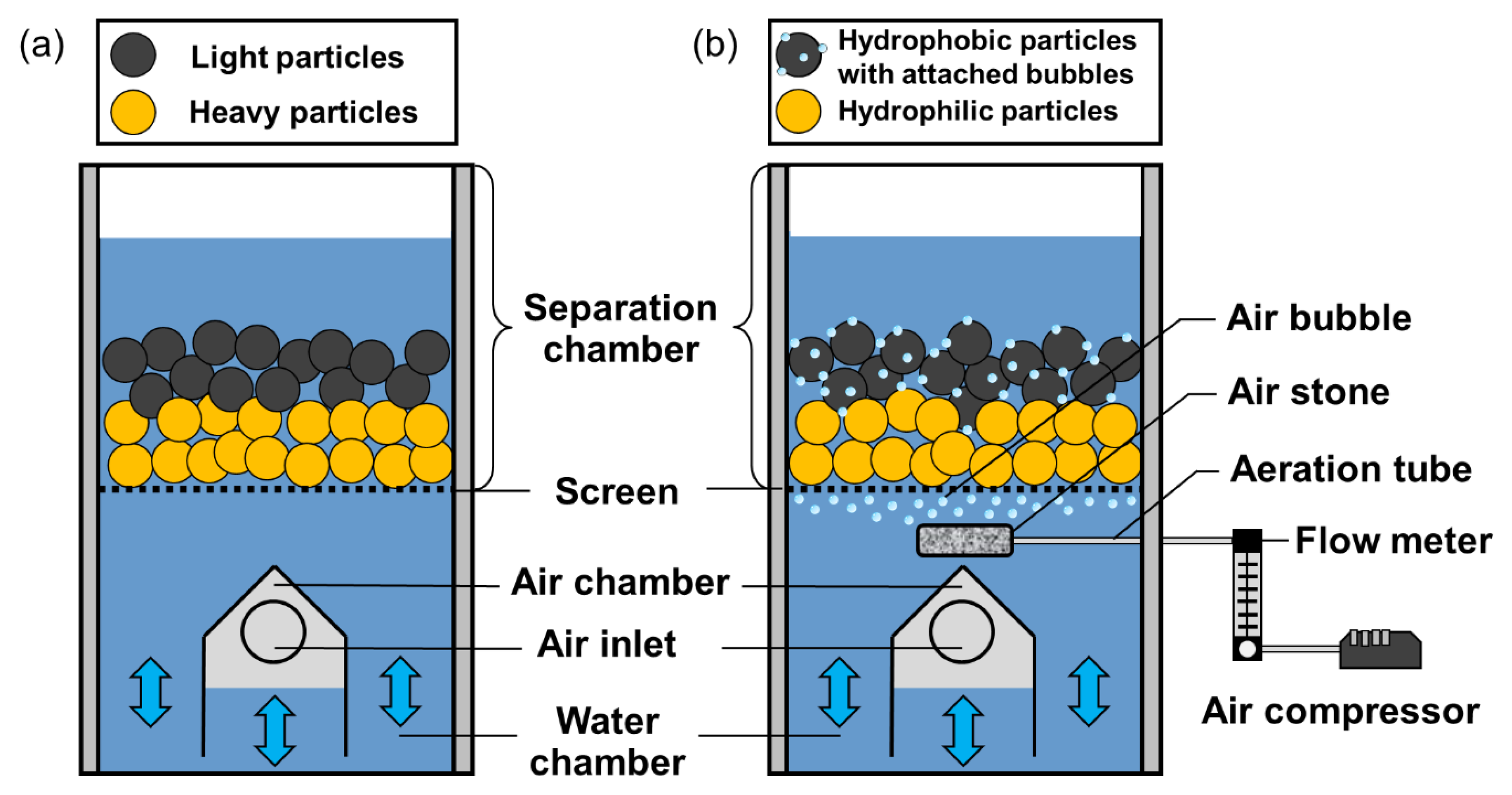
2.3. Hybrid Jig Separation Experiments

The hybrid jig experiments were carried out using the same jig described previously but with additional modifications including an air compressor, air flow meter, aeration tube, and air stone (Figure 1b). The samples and conditions were the same as that outlined in Section 2.2, except for the introduction of air bubbles into the separation chamber at an aeration rate of 1500 mL/min and addition of 20 ppm methyl isobutyl carbinol (MIBC, Sigma-Aldrich Co. Ltd., Saint-Quentin-Fallavier, Germany) to stabilize the bubbles (the conditions were selected based on the previous studies [28,29] and preliminary experiments).

2.4. Microencapsulation Experiments

For microencapsulation-hybrid jig separation, a +1.0–1.4 mm coal-pyrite mixture (80 g coal with 20 g pyrite) was reacted with 1 L of a solution containing 1 mM Fe2+ and 1 mM PO43− at pH 3 in a mechanical flotation cell with agitation speed of 1000 rpm and 500 mL/min aeration rate for 1 h. The aeration was adopted to promote the formation of coating by accelerating the rate of Fe2+ oxidation [32]. After microencapsulation, the samples were washed with DI water and then immediately used for microencapsulation-hybrid jig separation experiments. Additional experiments were conducted to evaluate the effects of pH on microencapsulation as follows: 0.8 g coal, 0.2 g pyrite, or 1 g coal-pyrite mixture (8:2 w/w) was reacted with 1 mM Fe2+ (prepared using FeSO4·7H2O) and 1 mM PO43− (prepared using KH2PO4) at pH 3 and 4 (controlled with HCl) in a constant temperature (25 °C) water bath shaker at 120 min−1 for 1 h. All of the chemicals used in this study were of reagent grade (Wako Pure Chemical Industries, Ltd., Osaka, Japan). After this, the pH of suspension was measured, and solid and liquid were separated by filtration using a 0.2 µm membrane filter. The leachate was analyzed by inductively coupled plasma atomic emission spectrometer (ICP-AES, ICPE9820, Shimadzu Corporation, Kyoto, Japan) to measure the changes in dissolved Fe and P concentrations. Meanwhile, the residues were thoroughly washed with DI water, dried in a vacuum oven at 40 °C for 24 h, and analyzed by X-ray photoelectron spectroscopy (XPS, JPS-9200, JEOL Ltd., Tokyo, Japan). The XPS analysis was conducted using an Al Kα X-ray source operated at 100 W (Voltage, 10 kV; Current, 10 mA) under ultrahigh vacuum conditions (approximately 10−7 Pa). The narrow-scan spectra were calibrated using the binding energy of adventitious carbon (C 1s) (285.0 eV) for charge correction and then processed using CasaXPS software (version 2.3.23).

3. Results and Discussion

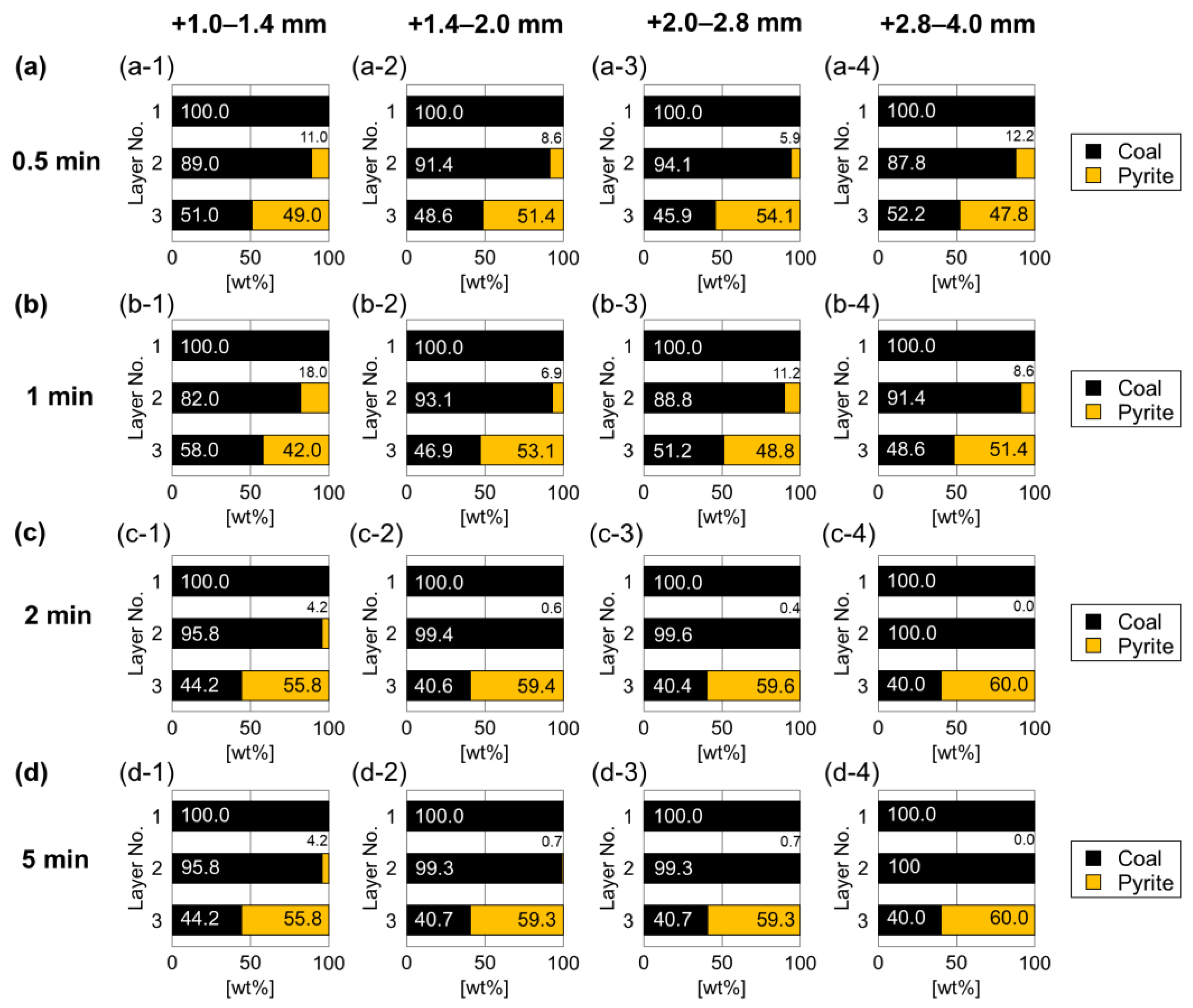
3.1. Effects of Particle Size and Separation Time on Jig Separation

To investigate the effects of separation time and particle size on the conventional jig separation, coal-pyrite mixtures of different size fractions: (i) +1.0–1.4, (ii) +1.4–2.0, (iii) +2.0–2.8, and (iv) +2.8–4.0 mm were used for jig separation experiments with separation time of (a) 0.5, (b) 1, (c) 2, and (d) 5 min. After the experiments, the products were divided into three layers from the top and “hand picking” (using tweezers) was carried out to separate coal from pyrite and determine the purity of the products.
Figure 2 shows the distribution of coal and pyrite in the different layers after jig separation. Under all conditions, coal was recovered without pyrite in the top layer while most of the pyrite was recovered in the bottom layer. However, a small portion of pyrite remained in the middle layer. Better separation was achieved when the particles were coarser and separation time was longer.
For the particles coarser than 1.4 mm, pyrite content in the middle layer decreased after separation for 2 min to <1% (S < 0.5%), which can be categorized as low S coal commonly used for combustion [38].
For smaller particles (+1–1.4 mm), however, the pyrite content in the middle layer remained substantial even after 5 min of separation. These results suggest that when the particles become fine, the jig separation of coal and pyrite becomes more difficult, resulting in lower efficiency of separation. In addition, it was found that some fine particles (+1–1.4 mm) could pass through the bottom screen during the separation and fall into the water chamber despite the bottom screen having an aperture size of 1 mm. This could be attributed to the abrasion between particles induced by water pulsation, which caused size reduction during jig separation. These fine particles then pass through the screen due to the suction force caused by water pulsation.

3.2. Effects of Particle Size and Separation Time on the Hybrid Jig Separation

To investigate the effects of separation time, particle size, and presence of bubbles on the hybrid jig separation, the experiments were carried out with the same conditions as the jig separation tests but aerated at 1500 mL/min to generate air bubbles stabilized with 20 ppm of MIBC.
Figure 3 shows the distribution of coal and pyrite in the different layers after hybrid jig separation. Similar to the jig separation results, coal was recovered without pyrite in the top layer (100% coal), most of pyrite settled down in the bottom layer, and a mixture of coal and pyrite was observed in the middle layer. For particles coarser than 1.4 mm, separation time and particle size had insignificant effects because the amount of pyrite in the middle layer were similar for all conditions. When the pyrite content of the middle layer in the jig experiments were compared with those in hybrid jig, those in the latter were higher than the former.
In the case of +1.0–1.4 mm size fraction, the separation efficiency decreased with time as the content of pyrite in the middle layer increased. It was also found that, only few amount of fine particles passed through the bottom screen of the hybrid jig (10.0 ± 4.7%) compared with the conventional jig (28.6 ± 15.4%). These results suggest that rising air bubbles could limit consolidation tricking of fine particle through the particle bed, ragging layer, and screen during the suction stage. Moreover, bubbles could attach to both coal and pyrite because these materials are hydrophobic [31]. Significant amounts of air bubbles were attached to fine particles, which could be attributed to the larger surface area per volume of fine particles than coarse particles. This phenomenon may contribute to the agglomeration of coal and pyrite, resulting in lower separation efficiency when the separation time is longer. To improve the separation efficiency, selective surface modification using microencapsulation was carried out to render the surface of pyrite hydrophilic and separate this mineral from hydrophobic coal more easily. In this paper, microencapsulation was used to coat pyrite with hydrophilic iron phosphate.

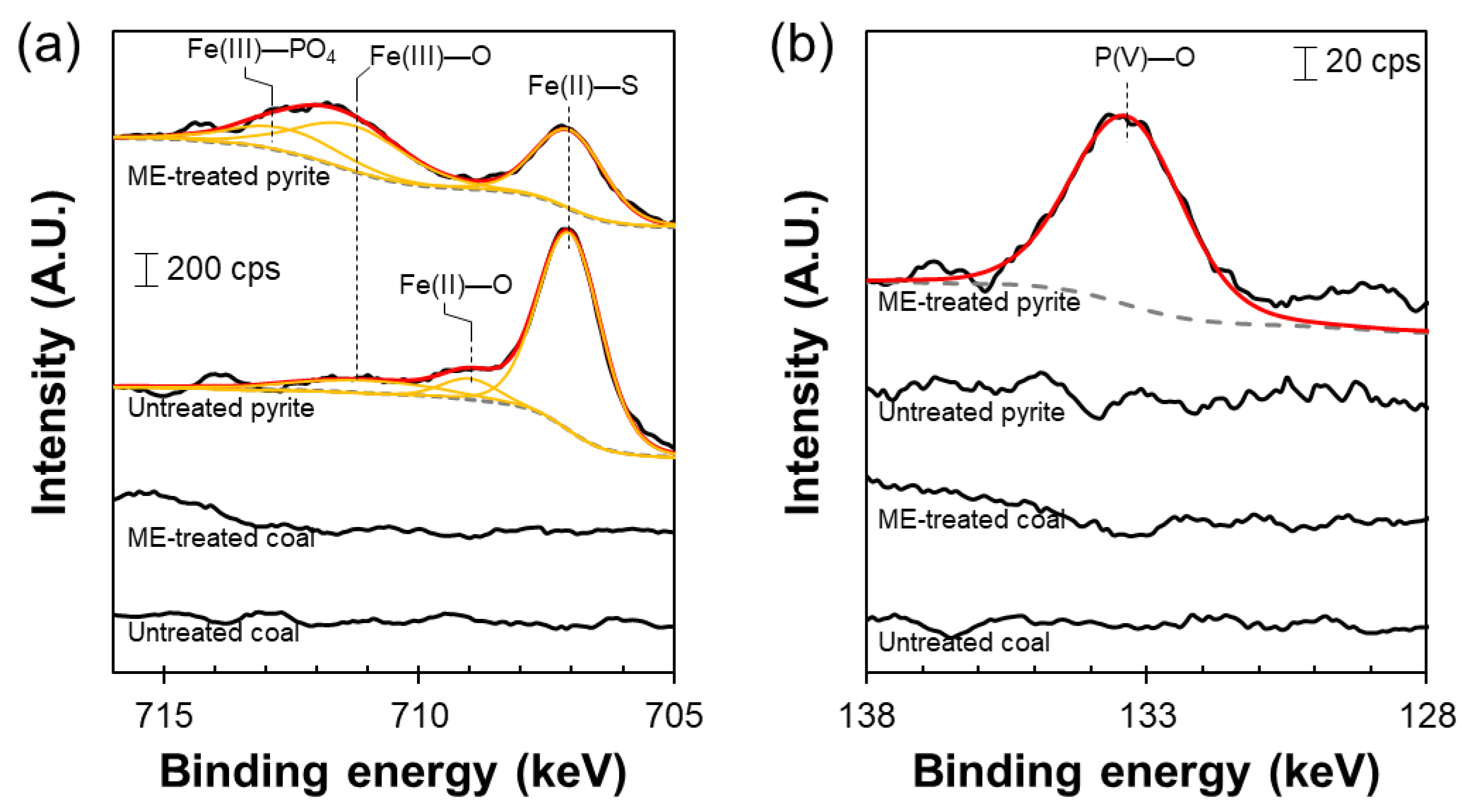
3.3. Effects of Microencapsulation as Pretreatment on Hybrid Jig Separation

Figure 4 shows the changes in dissolved Fe and P concentrations after microencapsulation treatment of coal, pyrite, and their mixture at pH 4 (Figure 4a,b) and pH 3 (Figure 4c,d). When pyrite was treated at pH 4, dissolved P concentration decreased, which implies that it was precipitated with Fe3+ as FePO4 (Equations (7) and (8)). However, dissolved Fe concentration was almost constant because Fe2+ is released when pyrite is oxidized.
4Fe2+ + O2(aq) + 4H+ → 4Fe3+ + 2H2O
Fe3+ + H2PO4 → FePO4↓ + 2H+
It is important to note that dissolved Fe and P concentrations decreased after microencapsulation treatment of coal at pH 4. Although coal has a high electrical resistivity that limits Fe2+ oxidation, dissolved Fe and P were precipitated. This is due to the increase in solution pH, resulting from the protonation of functional groups of coal [39].
After microencapsulation treatment of coal, the solution pH increased from 4 to 5, where the rate of Fe2+ oxidation by dissolved oxygen (DO) is more than 10 times faster than that at pH 4 [40]. Thus, the selective hydrophilization of pyrite cannot be achieved by microencapsulation at pH 4.
To selectively form FePO4 coating on the surface of pyrite, microencapsulation treatment was conducted at pH 3. As shown in Figure 4c,d, dissolved Fe and P were not precipitated when treating coal because the solution pH was 3.2 wherein Fe2+ oxidation by DO hardly occurs. Meanwhile, in the presence of pyrite, dissolved Fe and P concentrations decreased, indicating that FePO4 precipitates were formed on the surface of pyrite. To clarify the selective formation of FePO4 coating on pyrite, coal, and pyrite with and without microencapsulation treatment were analyzed by XPS. The XPS Fe 2p3/2 spectra of untreated and treated coal show that no distinct peaks were observed, which revealed that FePO4 coating was not formed on the surface of coal (Figure 5a). In the case of untreated pyrite, it shows a major peak at 707.2 eV attributed to pyrite (Fe(II)—S) and two minor peaks of oxidation products at 709.1 eV (Fe(II)—O) and 711.3 eV (Fe(III)—O) [41]. The XPS Fe 2p3/2 spectrum of treated pyrite shows an additional peak at ~713 eV assigned to Fe(III)—PO4 [42]. Moreover, the XPS P 2p spectrum of treated pyrite only shows a single peak at 133.4 eV, which is assigned to P(V)—O binding energy of ferric phosphate [4,43]. Thus, it was confirmed that microencapsulation using Fe2+ and PO43− at pH forms FePO4 coating selectively on the surface of pyrite.
Figure 6 shows the distribution of coal and pyrite in each layer after conventional jig, hybrid jig, and hybrid jig with microencapsulation of +1.0–1.4 mm coal-pyrite mixture at separation time of 0.5 and 5 min and Table 1 shows the purity and recovery of coal in the products. As discussed earlier in Section 3.1 and Section 3.2, conventional jig separation for 5 min could not achieve the low S coal target (Figure 6(b-1)). With the hybrid jig, separation for 0.5 min was better than the conventional jig (Figure 6(a-1,a-2)), but efficiency decreased when the separation time was longer (Figure 6(b-2)). In comparison, the results for hybrid jig with microencapsulation showed that at separation time of 0.5 min, the pyrite content in the middle layer was 1% (S = 0.5%) (Figure 6(a-3)), which can be categorized as low-S coal commonly used for combustion. Moreover, a longer separation time of 5 min produced an almost pure coal in the middle layer (Figure 6(b-3)). It was also found that fewer bubbles attached to the pyrite, and bubble-induced agglomeration of coal and pyrite was limited even at longer separation time of 5 min. These results indicate that microencapsulation modified the pyrite surface from being hydrophobic to hydrophilic largely because of the formation of iron phosphate coating, a process that not only improved hybrid jig efficiency but also shortened the required time for separation.
From the results obtained above, it could be concluded that the pre-treatment using microencapsulation could improve the separation efficiency of coal and pyrite compared with the conventional jig and hybrid jig separation as well as prevent the AMD generation at the same time. The techniques that were first developed in this paper could be advantageous to various sectors. For academics and researches, this technique could be one of the examples of how different techniques in mineral processing and environmental chemistry were applied and combined to solve a problem in both industry and the environment at the same time. For an economic viewpoint, the improvement of the coal cleaning efficiency could (i) reduce the usage of natural resources, (ii) reduce waste generation and pollution, and (iii) reduce the cost of other clean coal technologies (i.e., in-combustion and post-combustion) as well as the AMD treatment. Finally, for the society and environment, this novel coal cleaning method could be the choice to turn coal into a cheap, clean, and sustainable energy resource, and contribute to UN-SDG #7 “Affordable and clean energy”, especially for low-income and developing countries, the negative impacts to society and the environment of coal utilization should be reduced [1].

4. Conclusions

This study is the first to develop the microencapsulation-hybrid jig separation method as a clean coal technology to separate coal and pyrite in the particle size range of 1–4 mm. The findings of this study are as follows:
  • For the conventional jig, most of coal and pyrite could be recovered in the top and bottom layers, respectively. In the middle layer, no pyrite was present for +2.8–4.0 mm size fraction, only a few pyrite (less than 1%) was found in +1.4–2.0 and +2.0–2.8 mm size fractions, and 4.2% pyrite remained for +1.0–1.4 mm size fraction, indicating that separation is more difficult when particle size is reduced.
  • For hybrid jig separation without microencapsulation, the top and bottom layers contain clean coal and pyrite, respectively, similar to the conventional jig. However, the required time for separation in the hybrid jig (0.5 min) was shorter than in the conventional jig (2 min).
  • Higher pyrite content was found in the middle layer of hybrid jig especially in the +1.0–1.4 size fraction, suggesting that at <1.4 mm separation of pyrite and coal was less efficient.
  • The worst results were found with +1.0–1.4 mm fraction and longer separation time, which could be attributed to bubble-induced agglomeration of fine, hydrophobic coal and pyrite.
  • Microencapsulation-hybrid jig separation dramatically shortened the separation time and improved the separation efficiency because of the selective formation of hydrophilic iron phosphate coating on pyrite.
  • For processing coals containing finely dispersed pyrite, the size reduction to achieve a sufficient liberation of coal from pyrite is necessary. In contrast to conventional jig, microencapsulation-hybrid jigs can produce low S coal from coal/pyrite mixture with a size fraction of +1.0–1.4 mm. Thus, micro-encapsulation-hybrid jig will contribute to the processing of coals that is difficult to be cleaned by conventional jig. In addition, pyrite is covered with a surface protective coating that will contribute to the suppression of AMD formation caused by pyrite oxidation.

Supplementary Materials

The following supporting information can be downloaded at: https://www.mdpi.com/article/10.3390/en16052432/s1, Figure S1: A photograph of a bench-scale batch-type jig with coal and pyrite particles that are partitioned into three layers after separation.

Author Contributions

Conceptualization, T.P., I.P. and M.I.; methodology, T.P., I.P., J.P., P.S. and C.K.; validation, T.P., I.P., J.P., P.S., C.K. and M.I.; formal analysis, T.P., I.P., J.P., P.S., C.K. and O.J.; investigation, T.P., I.P., J.P., P.S. and C.K.; data curation, T.P., I.P., J.P., P.S. and C.K.; writing—original draft, T.P., I.P., J.P., P.S. and C.K.; writing—review & editing; T.P., I.P., J.P., P.S., C.K., C.B.T. and M.I.; visualization, T.P. and I.P.; supervision, T.P., I.P., N.P., O.J., C.B.T., N.H. and M.I.; project administration, T.P. All authors have read and agreed to the published version of the manuscript.

Funding

This work was financially supported by the Thailand Science Research and Innovation (TSRI) Fund of Chulalongkorn University under the project “Georesources Engineering Project: Research and Capacity Building” (CU_FRB640001_01_21_4).

Institutional Review Board Statement

Not applicable.

Informed Consent Statement

Not applicable.

Data Availability Statement

Not applicable.

Acknowledgments

The authors gratefully acknowledge the editors and anonymous reviewers for their valuable inputs to this paper. The authors also wish to thank the members of Laboratory of Mineral Processing and Resources Recycling, Division of Sustainable Resources Engineering, Faculty of Engineering, Hokkaido University and Department of Mining and Petroleum Engineering, Faculty of Engineering, Chulalongkorn University for their support of this research.

Conflicts of Interest

The authors declare no conflict of interest.

References

  1. Phengsaart, T.; Srichonphaisan, P.; Kertbundit, C.; Soonthornwiphat, N.; Sinthugoot, S.; Phumkokrux, N.; Juntarasakul, O.; Maneeintr, K.; Numprasanthai, A.; Park, I.; et al. Conventional and recent advances in gravity separation technologies for coal cleaning: A systematic and critical review. Heliyon 2023, 9, e13083. [Google Scholar] [CrossRef] [PubMed]
  2. Gaffney, J.S.; Marley, N.A. The impacts of combustion emissions on air quality and climate—From coal to biofuels and be-yond. Atmos. Environ. 2009, 43, 23–36. [Google Scholar] [CrossRef]
  3. Zhou, Y.; Xu, P.; Cheng, H.; Liu, Q. Thermal phase transition of pyrite from coal. J. Therm. Anal. Calorim. 2015, 134, 2391–2396. [Google Scholar] [CrossRef]
  4. Park, I.; Hong, S.; Jeon, S.; Ito, M.; Hiroyoshi, N. Flotation separation of chalcopyrite and molybdenite assisted by microencapsulation using ferrous and phosphate ions: Part I. Selective coating formation. Metals 2020, 10, 1667. [Google Scholar] [CrossRef]
  5. Guan, G. Clean coal technologies in Japan: A review. Chin. J. Chem. Eng. 2017, 25, 689–697. [Google Scholar] [CrossRef]
  6. Liu, Z.; Shi, S.; Li, Y. Coal liquefaction technologies—Development in China and challenges in chemical reaction engineering. Chem. Eng. Sci. 2010, 65, 12–17. [Google Scholar] [CrossRef]
  7. Minchener, A.J. Coal gasification for advanced power generation. Fuel 2005, 84, 2222–2235. [Google Scholar] [CrossRef]
  8. Sen, S. An overview of clean coal technologies I: Pre-combustion and post-combustion emission control. Energy Sources B Econ. Plan. Policy 2010, 5, 261–271. [Google Scholar] [CrossRef]
  9. Zhang, Y.; Shen, Z.; Zhang, B.; Sun, J.; Zhang, L.; Zhang, T.; Xu, H.; Bei, N.; Tian, J.; Wang, Q.; et al. Emission reduction effect on PM2.5, SO2 and NOx by using red mud as additive in clean coal briquetting. Atmos. Environ. 2020, 223, 117203. [Google Scholar] [CrossRef]
  10. Topper, J.M.; Cross, P.J.I.; Goldthorpe, S.H. Clean coal technology for power and cogeneration. Fuel 1994, 73, 1056–1063. [Google Scholar] [CrossRef]
  11. Hutson, N.D.; Krzyzynska, R.; Srivastava, R.K. Simultaneous removal of SO2, NOx, and Hg from coal flue gas using a NaClO2-enhanced wet scrubber. Ind. Eng. Chem. Res. 2008, 47, 5825–5831. [Google Scholar] [CrossRef]
  12. Maneeintr, K.; Henni, A.; Idem, R.O.; Tontiwachwuthikul, P.; Wee, A.G.H. Physical and transport properties of aqueous amino alcohol solutions for CO2 capture from flue gas streams. Process. Saf. Environ. Prot. 2008, 86, 291–295. [Google Scholar] [CrossRef]
  13. Maneeintr, K.; Idem, R.O.; Tontiwachwuthikul, P.; Wee, A.G.H. Comparative mass transfer performance studies of CO2 absorption into squeous solutions of DEAB and MEA. Ind. Eng. Chem. Res. 2010, 49, 2857–2863. [Google Scholar] [CrossRef]
  14. Maneeintr, K.; Photien, K.; Charinpanitkul, T. Mixture of MEA/2-MAE for effective CO2 capture from flue gas stream. Chem. Eng. Trans. 2018, 63, 229–234. [Google Scholar] [CrossRef]
  15. Noda, N.; Makino, H. Influence of operating temperature on performance of electrostatic precipitator for pulverized coal combustion boiler. Adv. Powder Technol. 2010, 21, 495–499. [Google Scholar] [CrossRef]
  16. Yoosook, H.; Maneeintr, K. CO2 geological storage coupled with water alternating gas for enhanced oil recovery. Chem. Eng. Trans. 2018, 63, 217–222. [Google Scholar] [CrossRef]
  17. Zhao, L.; Li, C.; Zhang, X.; Zeng, G.; Zhang, J.; Xie, Y. A review on oxidation of elemental mercury from coal-fired flue gas with selective catalytic reduction catalysts. Catal. Sci. Technol. 2015, 5, 3459–3472. [Google Scholar] [CrossRef]
  18. Lejre, K.H.L.; Glarborg, P.; Christensen, H.; Mayer, S.; Kiil, S. Experimental investigation and mathematical modeling of the reaction between SO2(g) and CaCO3(s)-containing micelles in lube oil for large two-stroke marine diesel engines. Chem. Eng. J. 2020, 388, 124188. [Google Scholar] [CrossRef]
  19. Pyka, I.; Wierzchowski, K. Influence of equal settling particles on fine coal separation in water-only cyclones. Int. J. Coal Prep. Util. 2019, 42, 410–420. [Google Scholar] [CrossRef]
  20. Wang, Q.; Lu, J.; Yin, W.; Yang, H.; Wei, L. Numerical study of gas-solid flow in a coal beneficiation fluidized bed using kinetic theory of granular flow. Fuel Process. Technol. 2013, 111, 29–41. [Google Scholar] [CrossRef]
  21. Shahzad, M.; Ali, Z. Short communication cleaning of Dalwal-Punjab coal by using shaking table. Pak. J. Sci. Ind. Res. 2018, 61, 56–58. [Google Scholar] [CrossRef]
  22. Shahzad, M.; Ali, Z. A simple and efficient process for small-scale cleaning of poorly liberated, difficult-to-wash low-rank coal. Energy Sources A Recovery Util. Environ. Eff. 2019, 1–14. [Google Scholar] [CrossRef]
  23. Chalavadi, G.; Singh, R.K.; Sharma, M.; Das, A. Recovery of combustibles from fine coal through controlled air fluidization over inclined deck. Sep. Sci. Technol. 2015, 50, 2032–2040. [Google Scholar] [CrossRef]
  24. Chalavadi, G.; Singh, R.K.; Sharma, M.; Singh, R. Development of a generalized strategy for dry beneficiation of fine coal over a vibrating inclined deck. Int. J. Coal Prep. Util. 2016, 36, 10–27. [Google Scholar] [CrossRef]
  25. Mohanty, M.; Zhang, B.; Wang, H.; Mahajan, A.; Akbari, H.; Bashir, Z.; Ramamoorthy, S.; Hirschi, J. Development and demonstration of an automation and control system for coal spirals. Int. J. Coal Prep. Util. 2014, 34, 157–171. [Google Scholar] [CrossRef]
  26. Hori, K.; Tsunekawa, M.; Ueda, M.; Hiroyoshi, N.; Ito, M.; Okada, H. Development of a new gravity separator for plastics—A hybrid-jig—. Mater. Trans. 2009, 50, 2844–2847. [Google Scholar] [CrossRef] [Green Version]
  27. Ito, M.; Saito, A.; Murase, N.; Phengsaart, T.; Kimura, S.; Tabelin, C.B.; Hiroyoshi, N. Development of suitable product recovery systems of continuous hybrid jig for plastic-plastic separation. Miner. Eng. 2019, 141, 105839. [Google Scholar] [CrossRef]
  28. Ito, M.; Takeuchi, M.; Saito, A.; Murase, N.; Phengsaart, T.; Tabelin, C.B.; Hiroyoshi, N.; Tsunekawa, M. Improvement of hybrid jig separation efficiency using wetting agents for the recycling of mixed-plastic wastes. J Mater. Cycles Waste Manag. 2019, 21, 1376–1383. [Google Scholar] [CrossRef]
  29. Ito, M.; Takeuchi, M.; Saito, A.; Murase, N.; Phengsaart, T.; Kimura, S.; Kitajima, N.; Tabelin, C.B.; Hiroyoshi, N. Estimation of hybrid jig separation efficiency using a modified concentration criterion based on apparent densities of plastic particles with attached bubbles. J. Mater. Cycles Waste Manag. 2020, 22, 2071–2080. [Google Scholar] [CrossRef]
  30. Jeon, S.; Ito, M.; Tabelin, C.B.; Pongsumrankul, R.; Tanaka, S.; Kitajima, N.; Saito, A.; Park, I.; Hiroyoshi, N. A physical separation scheme to improve ammonium thiosulfate leaching of gold by separation of base metals in crushed mobile phones. Miner. Eng. 2019, 138, 168–177. [Google Scholar] [CrossRef]
  31. Hornn, V.; Ito, M.; Shimada, H.; Tabelin, C.B.; Jeon, S.; Park, I.; Hiroyoshi, N. Agglomeration–Flotation of Finely Ground Chalcopyrite using Emulsified Oil Stabilized by Emulsifiers: Implications for Porphyry Copper Ore Flotation. Metals 2020, 10, 912. [Google Scholar] [CrossRef]
  32. Seng, S.; Tabelin, C.B.; Makino, Y.; Chea, M.; Phengsaart, T.; Park, I.; Hiroyoshi, N.; Ito, M. Improvement of flotation and suppression of pyrite oxidation using phosphate-enhanced galvanic microencapsulation (GME) in a ball mill with steel ball media. Miner. Eng. 2019, 143, 105931. [Google Scholar] [CrossRef]
  33. Park, I.; Hong, S.; Jeon, S.; Ito, M.; Hiroyoshi, N. Flotation separation of chalcopyrite and molybdenite assisted by microencapsulation using ferrous and phosphate ions: Part II. Flotation. Metals 2020, 11, 439. [Google Scholar] [CrossRef]
  34. Duba, A.G. Electrical conductivity of coal and coal char. Fuel 1977, 56, 441–443. [Google Scholar] [CrossRef]
  35. Shao, Z.; Wang, D.; Wang, Y.; Zhong, X.; Tang, X.; Xi, D. Electrical resistivity of coal-bearing rocks under high temperature and the detection of coal fires using electrical resistance tomography. Geophys. J. Int. 2016, 204, 1316–1331. [Google Scholar] [CrossRef]
  36. Ferrer, I.J.; Nevskala, D.M.; de las Heras, C.; Sanchez, C. About the band gap nature of FeS2 as determined from optical and photoelectrochemical measurements. Solid State Commun. 1990, 74, 913–916. [Google Scholar] [CrossRef]
  37. McKibben, M.A.; Barnes, H.L. Oxidation of pyrite in low temperature acidic solutions: Rate laws and surface textures. Geochim. Cosmochim. Acta 1986, 50, 1509–1520. [Google Scholar] [CrossRef]
  38. Chou, C. Sulfur in coals: A review of geochemistry and origins. Int. J. Coal Geol. 2012, 100, 1–13. [Google Scholar] [CrossRef]
  39. Dil, E.A.; Ghaedi, M.; Ghaedi, A.M.; Asfaram, A.; Goudarzi, A.; Hajati, S.; Soylak, M.; Agarwal, S.; Gupta, V.K. Modeling of quaternary dyes adsorption onto ZnO–NR–AC artificial neural network: Analysis by derivative spectrophotometry. J. Ind. Eng. Chem. 2016, 34, 186–197. [Google Scholar] [CrossRef]
  40. Stumm, W.; Morgan, J.J. Aquatic Chemistry: Chemical Equilibria and Rates in Natural Waters; Wiley-Interscience: New York, NY, USA, 1996. [Google Scholar]
  41. Descostes, M.; Mercier, F.; Thromat, N.; Beaucaire, C.; Gautier-Soyer, M. Use of XPS in the determination of chemical environment and oxidation state of iron and sulfur samples: Constitution of a data basis in binding energies for Fe and S reference compounds and applications to the evidence of surface species of an oxidized pyrite in a carbonate medium. Appl. Surf. Sci. 2000, 165, 288–302. [Google Scholar] [CrossRef]
  42. Wang, Y.; Feng, Z.; Wang, L.; Yu, L.; Chen, J.; Liang, Z.; Wang, R. A joint experimental and theoretical study on the effect of manganese doping on the structural, electrochemical and physical properties of lithium iron phosphate. RSC Adv. 2014, 4, 51609–51614. [Google Scholar] [CrossRef]
  43. Zeng, L.; Li, X.; Shi, Y.; Qi, Y.; Huang, D.; Tadé, M.; Wang, S.; Liu, S. FePO4 based single chamber air-cathode microbial fuel cell for online monitoring levofloxacin. Biosens. Bioelectron. 2017, 91, 367–373. [Google Scholar] [CrossRef] [PubMed]
Figure 1. Schematic illustrations of batch-type (a) jig, and (b) hybrid jig used in this study.
Energies 16 02432 g001
Figure 2. Distribution of coal and pyrite in each layer after jig separation at separation time of (a) 0.5 min of (a-1) +1.0–1.4, (a-2) +1.4–2.0, (a-3) +2.0–2.8, and (a-4) +2.8–4.0 mm; (b) 1 min of (b-1) +1.0–1.4, (b-2) +1.4–2.0, (b-3) +2.0–2.8, and (b-4) +2.8–4.0 mm; (c) 2 min of (c-1) +1.0–1.4, (c-2) +1.4–2.0, (c-3) +2.0–2.8, and (c-4) +2.8–4.0 mm; (d) 5 min of (d-1) +1.0–1.4, (d-2) +1.4–2.0, (d-3) +2.0–2.8, and (d-4) +2.8–4.0 mm.
Energies 16 02432 g002
Figure 3. Distribution of coal and pyrite in each layer after hybrid jig separation at separation times of (a) 0.5 min of (a-1) +1.0–1.4, (a-2) +1.4–2.0, (a-3) +2.0–2.8, and (a-4) +2.8–4.0 mm; (b) 1 min of (b-1) +1.0–1.4, (b-2) +1.4–2.0, (b-3) +2.0–2.8, and (b-4) +2.8–4.0 mm; (c) 2 min of (c-1) +1.0–1.4, (c-2) +1.4–2.0, (c-3) +2.0–2.8, and (c-4) +2.8–4.0 mm; (d) 5 min of (d-1) +1.0–1.4, (d-2) +1.4–2.0, (d-3) +2.0–2.8, and (d-4) +2.8–4.0 mm.
Energies 16 02432 g003
Figure 4. The changes in dissolved Fe and P concentrations after microencapsulation treatment of pyrite, coal, and coal-pyrite mixture at pH 4 ((a,b)) and pH 3 ((c,d)).
Energies 16 02432 g004
Figure 5. The XPS spectra of untreated and ME-treated coal and pyrite: (a) Fe 2p3/2 and (b) P 2p (Note that “ME” means microencapsulation).
Energies 16 02432 g005
Figure 6. Distribution of coal and pyrite in each layer after separation at +1.0–1.4 mm at separation time of (a) 0.5 min (a-1) jig separation, (a-2) hybrid jig separation, and (a-3) hybrid jig separation with microencapsulation pre-treatment, and (b) 5 min (b-1) jig separation, (b-2) hybrid jig separation, and (b-3) hybrid jig separation with microencapsulation pre-treatment.
Energies 16 02432 g006
Table 1. Purity and recovery of coal after the separation time of 0.5 and 5 min of difference jig separation of +1.0–1.4 mm coal/pyrite mixtures when difference layers are used as products.
Purity [%]Recovery [%]
Separation Time [min]0.55.00.55.0
Layer No.11 + 21 + 2 + 311 + 21 + 2 + 311 + 21 + 2 + 311 + 21 + 2 + 3
Jig100.094.580.0100.097.980.041.778.8100.041.781.6100.0
100.098.580.0100.086.580.041.782.1100.041.772.1100.0
100.099.580.0100.0100.080.041.782.9100.041.783.3100.0
Hybrid jig
w/o microencapsulation
100.094.580.0100.097.980.041.778.8100.041.781.6100.0
100.098.580.0100.086.580.041.782.1100.041.772.1100.0
Hybrid jig
w/ microencapsulation
100.099.580.0100.0100.080.041.782.9100.041.783.3100.0
100.094.580.0100.097.980.041.778.8100.041.781.6100.0
100.098.580.0100.086.580.041.782.1100.041.772.1100.0
100.099.580.0100.0100.080.041.782.9100.041.783.3100.0
Disclaimer/Publisher’s Note: The statements, opinions and data contained in all publications are solely those of the individual author(s) and contributor(s) and not of MDPI and/or the editor(s). MDPI and/or the editor(s) disclaim responsibility for any injury to people or property resulting from any ideas, methods, instructions or products referred to in the content.

