Review

Conservation Voltage Reduction in Modern Power Systems: Applications, Implementation, Quantification, and AI-Assisted Techniques

by
Alireza Gorjian
1,
Mohsen Eskandari
2,* and
Mohammad H. Moradi
1,*
1
Electrical Engineering Department, Faculty of Engineering, Bu-Ali Sina University, Hamedan 6516738695, Iran
2
The School of Electrical Engineering and Telecommunications, University of New South Wales, Sydney, NSW 2052, Australia
*
Authors to whom correspondence should be addressed.
Energies 2023, 16(5), 2502; https://doi.org/10.3390/en16052502
Submission received: 11 January 2023 / Revised: 17 February 2023 / Accepted: 2 March 2023 / Published: 6 March 2023
(This article belongs to the Special Issue Stability Issues and Challenges in Modern Electric Power Systems)

Abstract

:
Conservation voltage reduction (CVR) is a potentially effective and efficient technique for inertia synthesis and frequency support in modern grids comprising power electronics (PE)-based components, aiming to improve dynamic stability. However, due to the complexities of PE-based grids, implementing the CVR methods cannot be performed using traditional techniques as in conventional power systems. Further, quantifying the CVR impacts in modern grids, while focusing on dynamic time scales, is critical, consequently making the traditional methods deficient. This is an important issue as CVR utilization/quantification depends on grid conditions and CVR applications. Considering these concerns, this work offers a thorough analysis of CVR applications, implementation, and quantification strategies, including data-driven AI-based methods in PE-based modern grids. To assess the CVR applications from a new perspective, aiming to choose the proper implementation and quantification techniques, they are divided into categories depending on various time scales. CVR implementation methods are categorized into techniques applied to PE-based grids and islanded microgrids (MGs) where different control systems are adopted. Additionally, to address the evaluation issues in modern grids, CVR quantification techniques, including machine learning- and deep learning-based techniques and online perturbation-based methods are evaluated and divided based on the CVR application. Concerns with the further utilizing and measuring of CVR impacts in modern power systems are discussed in the future trends section, where new research areas are suggested.

1. Introduction

The stability of power systems should be preserved from various time scales, such as steady-state operation, dynamics, and faults transients, in each of which stability requirement should be achieved [1]. In this light, maintaining the balance between power production and consumption is the key factor. For example, from dynamics point view, instant balance should be held at the time scale of less than to a few seconds in power electronics (PE)-based modern grids. However, stabilizing PE-interfaced modern grids comprising inverter-interfaced distributed generation units (IIDGs) is challenging due to the multiple time scales of the control system of inverters. In addition, the high penetration of intermittent renewable energy sources (RESs) imposes more uncertainties to the grid which makes the stabilization scheme more complicated and more expensive [2].
Precisely, the system’s capability to provide the demanded active/reactive power in time has a significant impact on system stability, resulting in the smooth operation of the grid. To maintain the power production-consumption balance various types of control systems have been proposed in the literature and are used in PE-based power systems. For instance, deploying battery energy storage systems (BESSs) is a common method of resolving stability problems in modern grids. However, various shortcomings and drawbacks such as high investment and maintenance costs of BESSs can impose additional challenges to the power system operator [3].
The conservation voltage reduction (CVR) technique, which conventionally is used for peak shaving and demand reduction [4], can be an alternative/complementary solution for improving the dynamics stability. CVR is implemented by reducing the grid voltage which results in a reduction in power consumption based on the load-voltage sensitivity (LVS) [5]. Meanwhile, by controlling the voltage at the lower end of the voltage tolerance limit in dynamics, and consequently controlling the demanded active and reactive power, CVR can bring an instant balance in power production consumption at the dynamics time scale, resulting in improved grid stability. This is a remarkable achievement thanks to the fast response IIDGs provided that an appropriate control scheme for CVR is designed. Yet, CVR can also be a solution to economic and marketing problems by decreasing power consumption as a part of demand-side management programs in modern power systems.
Recently, CVR application in PE-based modern grids such as microgrids (MGs) comprising IIDGs has gained significant attention [6]. MGs are popular due to their high efficiency [7] and reliability in integrating IIDGs including RESs, BESSs, and smart loads (SLs) [8,9,10]. Further, the PE-based equipment is the key component, providing the necessary interface between the distributed energy resources (DERs), BESSs, and SLs to the grid [11]. However, the high penetration of PE interfaces and lack of physical inertia result in low inertia grids that consequently lead to critical frequency excursion and sharp dynamic instabilities [12]. CVR can be used as a frequency support approach in MGs with high IIDG penetration, providing the necessary inertia and subsequently addressing transient and dynamic instabilities. Hence, CVR increases the grid’s strength which prevents critical frequency deviations that consequently improve the flexibility and controllability of the micro sources (MSs) [13,14]. In general, CVR applications in modern grids that are carried out over various time scales to complete various tasks can be categorized as follows:
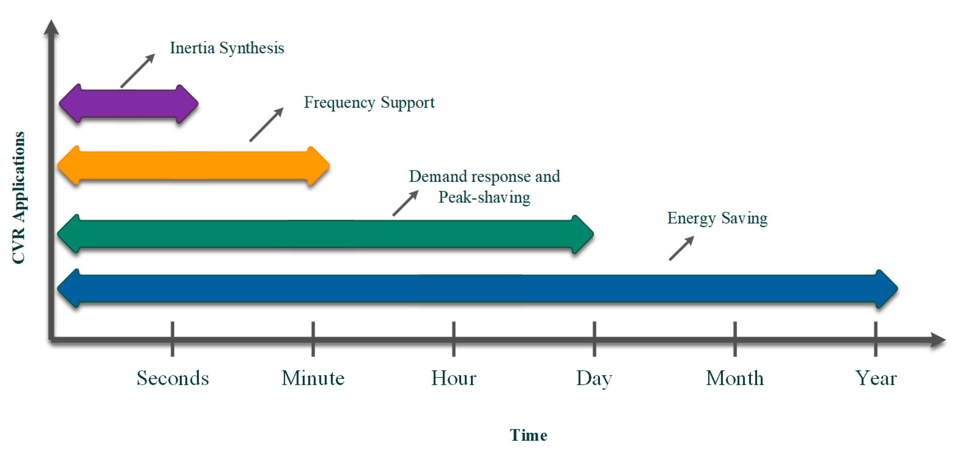
  • inertia synthesis and frequency support (seconds to a minute);
  • demand response and peak-shaving (minutes to hours);
  • energy-saving (hours to months/year).
Along with the CVR applications in PE-based grids, the CVR implementation technique is important and needs to be comprehensively studied. CVR implementation in modern grids is different from traditional techniques applied in conventional power systems. In addition, due to the different control structures of the grid-connected and autonomous MGs proper CVR implantation methods should be selected based on the CVR application. Other important factors such as the grid configuration (i.e., X/R ratio, grid topology) and load models highly affect CVR functionality, making the proper implementation technique a critical issue. Thereby, modern techniques are needed for advanced equipment such as smart inverters and SLs to effectively implement the CVR in PE-based grids with any configurations.
Furthermore, quantifying the CVR effects to maximize its impacts is another important issue that needs to be assessed. However, not all the CVR impacts on complicated PE-based power systems can be evaluated using traditional strategies. Therefore, to address the quantification issues during different time scales, novel quantification techniques such as online and also data-driven AI-based methods (i.e., machine learning and deep learning techniques) can be used. In light of this, quantification techniques should be categorized based on the CVR application to comprehensively assess CVR effects on modern grids.
Regarding the beneficial and potential impacts of the CVR in PE-based grids, there is still a lack of research on evaluating, reviewing, and comprehensively categorizing the CVR’s applications. This paper attempts to fill this great research gap by conducting a comprehensive review of CVR applications, utilization, and quantification in PE-based grids, particularly the control system of the inverters. In this light, CVR applications, implementation, and evaluation techniques are analyzed and categorized based on the grid configuration and CVR’s employment purpose. Suggestions for addressing the CVR challenges and complexities are also presented and new research areas in future trends are highlighted.
In summary, the contributions of this paper are listed as follows:
  • Review and classify the CVR applications in PE-based power systems: Conducting a very compact survey on CVR performance and categorizing the applications in modern grids, based on different time scales, from long-term applications including energy-conserving and peak demand reduction to short-term applications consisting of inertia synthesis and dynamics frequency support.
  • A comprehensive review of CVR implementation in PE-based grids: CVR implementation methods are categorized into techniques applied on grid-connected and islanded PE-based MGs where different control structures are adopted aiming to choose the proper utilization technique based on the CVR application.
  • Review of CVR quantification and evaluation methods: the quantification methods are categorized into quantifying the CVR’s long-term and short-term applications, including perturbation-based and also machine learning and deep learning strategies to choose the effective quantification method and equipment based on the CVR application.
  • Future trend: comprehensively analyzing the CVR utilization and quantification challenges to fill the existing gaps and to provide suggestions for further analysis and research.
The remainder of the paper is organized as follows: Section 2 describes the CVR fundamentals and applications in modern grids. CVR implementation methods and their achievements in PE-based grids are covered in Section 3. Section 4 presents the techniques of quantifying CVR impacts and Section 5 gives suggestions addressing the problems and challenges of CVR utilization and quantification in modern grids, intending to fill the existing research gaps for future trends. Finally, Section 6 concludes the paper and gives the final results.

2. CVR Applications

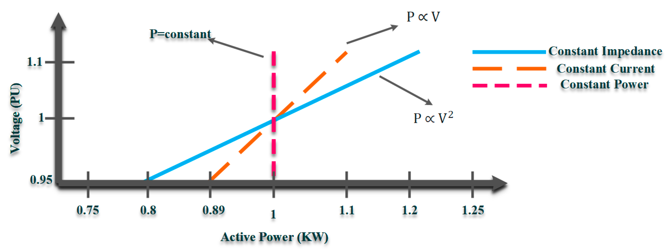
2.1. CVR Performance and Principles

CVR is a low-cost, convenient, and straightforward technology used in power systems employing the basic rules of LVS. Due to the voltage dependency of the demanded active/reactive power, CVR can be adopted to regulate power consumption through LVS and by adjusting the voltage level (voltage Mag. and/or phase). The power flow of a source-load model using ZIP (constant impedance (Z), constant current (I), and constant power (P)) as a common load model illustrates how the LVS basics can be articulated. Note that the ZIP load modeling technique takes into account the time-variant and thermal responses of the load model to the voltage alternation, making it a more accurate load modeling technique for CVR.
The power flow equations, including the injected active and reactive powers delivered from the source to the load terminal as the function of the voltage, can be expressed as follows.
P L = P 0 ( α 1 , P ( v v 0 ) 2 + α 2 , P ( v v 0 ) ) +   α 3 , P
Q L = Q 0 ( α 1 , q ( v v 0 ) 2 + α 2 , q ( v v 0 ) ) +   α 3 , q )
where P and Q are the active and reactive power demands, respectively. In addition, P 0 and Q 0 are the rated active and reactive power at the nominal voltage of V 0 , respectively. α 1 , P ( α 1 , q ), α 2 , P ( α 2 , q ) and α 3 , P ( α 3 , q ) are the constant impedance, constant current, and constant power coefficients of the active and reactive power demand, respectively. Accordingly, the relationship between instantaneous active power versus operating voltage for a sample ZIP load model can be driven as in Figure 1. Note that the same methodology can be driven for reactive power as well.
Based on LVS, the voltage sensitivity level varies according to different types of modern power networks as a result of several factors, including the grid’s configuration, load modeling, and the inductance to resistance (X/R) ratio. As illustrated in Figure 1, different load types exhibit diverse responses to CVR since LVS varies in terms of voltage dependency. CVR applications and impacts heavily rely on the different types of loads connected to the power network, and as a result, load modeling is crucial for CVR development. In light of this, a variety of load-modeling strategies are suggested in the literature, introducing various methodologies [16]. Further in-depth analysis of the ZIP and other load modeling techniques, such as the open/closed-loop approach considering the high penetration of RESs, can be found in [15,17,18].
Along with the LVS concept, CVR performance is based on the voltage standards and limitations, defined by the American National Standards Institute (ANSI) C84.1 [19]. These specifications outline the voltage limits of 60 Hz electric power suppliers, which operate between 100 V and 230 KV. The ANSI standards are primarily for steady-state time scales; however, the voltage level can go over these limits for transient and dynamic time scales. In this light, the information technology industry council curves cover voltage regions for transients and dynamics [19,20]. As a result, voltage mitigation for CVR through all applications takes place within the permitted range to prevent damage to appliances, utilities, and consumer products.

2.2. CVR Applications in Modern PE-Based Grids

In PE-based grids, CVR is adopted to address both stability and economic issues with a variety of applications over a range of time scales. Categorizing the CVR applications through their time scales provides a new perspective of distinguishing the CVR impact on PE-based grids that leads to using the appropriate CVR implementation techniques, as well as selecting the proper method to quantify and maximize its impacts. An overview of the CVR applications in modern power systems spanning various timescales is shown in Figure 2.

2.2.1. Demand Response, Peak-Shaving, and Energy-Saving via CVR

Reducing desired active/reactive power consumption to save energy is a straightforward CVR use in electric grids. Although the grid configuration and load model have a huge impact on the energy-conserving level, on average, each 1 percent voltage decrease by the CVR is equal to 0.8 percent in the demand power reduction [21]. The experimental results of a study employing several household load models undertaken to demonstrate the load model’s influence on the CVR’s energy-saving application are expressed in Table 1. As the constant power demand types retain the primary load power while utilizing the CVR and lowering the voltage level, it adversely influences these types of demand, such as the PC desktop, TV, PC monitor, and lighting. As a result, by decreasing the voltage, the current rises, increasing power consumption. From a different perspective, the energy consumption level in closed-loop load models, such as the induction stove, increases by lowering the voltage level, and therefore, by using the CVR, the current increases, leading to an increase in the energy consumption level.
In comparison with energy-saving, the CVR application on demand response and peak-shaving happen during a shorter timescale, whereas the employment methodologies are almost the same. To implement the CVR as an energy-saving and peak demand reduction approach in modern grids, DG sitting and sizing processes by considering limits on the voltage span region can be used to effectively reduce the energy consumption level [23,24,25,26,27,28,29,30]. The integration of DG and BESS placement with CVR indicates significant power reduction and increased energy savings, enhancing the system’s functionality and efficiency in the event of a load increase [31]. Further, CVR can have a significant impact on the economics of the power systems along with its applications in energy conservation, making it a practical option from an economic standpoint. In light of this, a Navigant research analysis indicates that the impact of CVR on North America will rise from USD 8.4 million in 2013 to more than USD 226 million by 2024 [32].
Despite the CVR’s beneficial impacts via long-term applications, the possible issue is the power quality. Specifically, lowering the voltage for a protracted period will cause the consumer’s appliances to face flicker issues, which also impacts the grid’s RMS voltage [33]. A further concern is the under-voltage issue, which results in the instability of power quality. However, studies indicate that the risk of under-voltage by CVR schemes is minimal and that it rarely can result in serious issues [34].

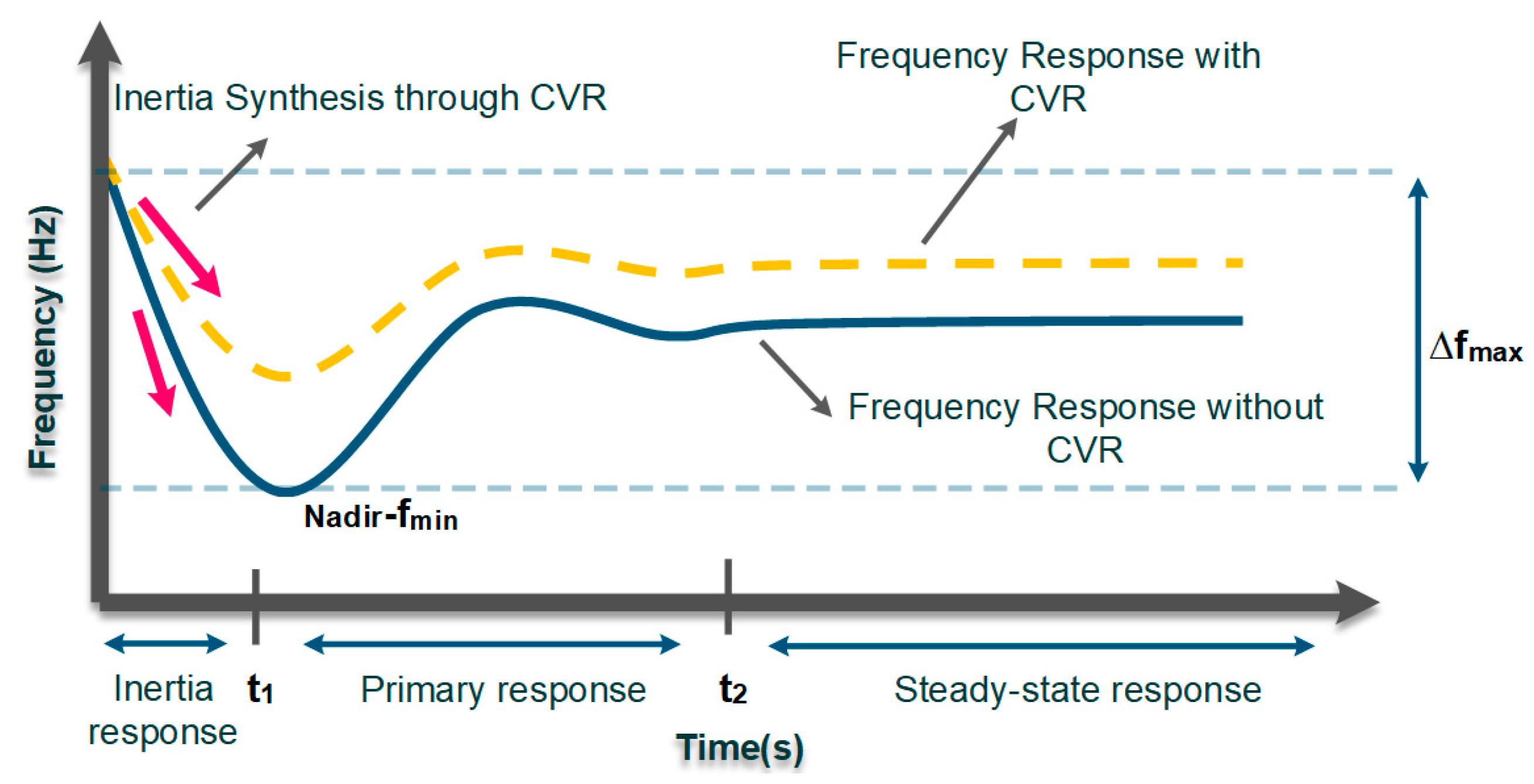
2.2.2. Inertia Synthesis and Dynamics Frequency Support via CVR

IIDGs owe their connectivity to the emerging advancements in power-electronics technologies, which raise control and stability challenges. MG concepts have been created in the context of smart grids to address control and management issues associated with the high penetration of RESs. However, due to the absence of rotatory mass in PE-based networks, the lack of inertia is a major problem that causes crucial transient and dynamic instabilities as well as excessive frequency fluctuations [35]. Inertia is essential for stabilizing the power system and also smoothing the transient and dynamic response of the power grids. Thus, insufficient inertia in PE-based grids directly impacts the frequency nadir (fmin) and the rate of change of frequency (RoCoF), which is defined as follows:
R o C o F = d f d t 1 I n e r t i a 1 H
where H is the inertia constant. It is important to note that pole slipping events that result in critical dynamic instabilities can be caused by RoCoF ranges between 1.5 Hz and 2 Hz [36]. In order to address the aforementioned issues, inertia synthesis and frequency support via CVR is a practical solution aimed at enhancing transient and dynamic stability in PE-based grids (see Figure 3). As the yellow dashed line illustrates by regulating the demand side voltage level and subsequently the demanded active/reactive power, CVR can boost the inertia level by maintaining an instant balance in power generation and consumption. Note that although CVR can be used to improve the steady-state frequency response this is not a common approach in the literature. Due to the fast response of inverters, SLs have recently attracted considerable attention in managing the inertia level of inverter-interfaced systems via CVR (detailed application of SLs on frequency support by CVR is described in Section 3). As a result, the SL functionality through CVR allows for a reduction in RoCoF and an increase in the inertia constant (H). Accordingly, CVR can provide adequate transient and dynamic stability with the primary goal of minimizing the maximum frequency fluctuations (∆fmax) by raising the inertia level and lowering RoCoF. An 18% drop in the maximum frequency deviation and a 40% decrease in RoCoF were found in the experimental research of inertia synthesis and primary frequency support by CVR, demonstrating the capabilities of CVR without relying on BESSs [37].

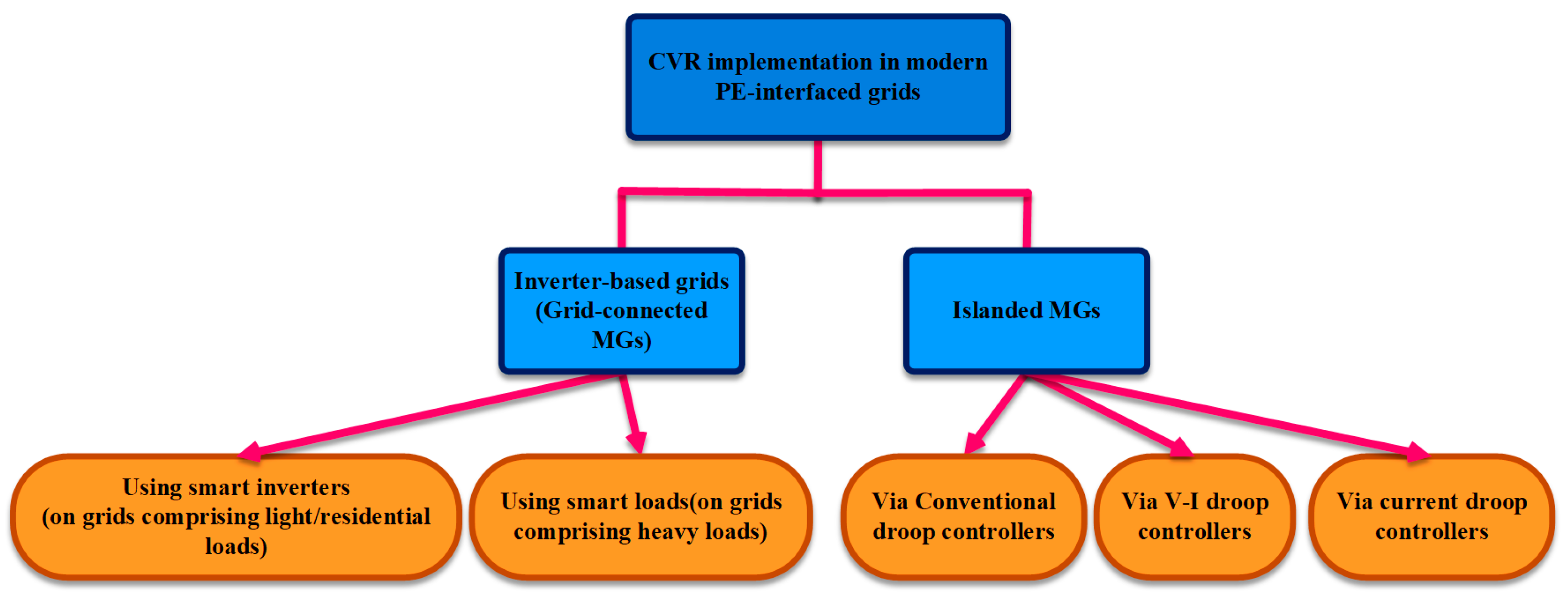
3. CVR Implementation Techniques in Modern Grids

In conventional power systems with synchronous generators, CVR utilization strategies aiming to conserve energy are split into two broad categories namely, open-loop and closed-loop techniques. Electromechanical voltage regulating devices, such as on-load tap changers (OLTCs), line drop compensators, and capacitor banks, are used to utilize CVR through open-loop procedures without measuring the voltage as a feedback signal [38,39,40,41]. The closed-loop techniques take voltage feedback into account using advanced metering infrastructure, supervisory control and data acquisition (SCADA) systems, and distributed management systems with advanced functionalities. Thereby, in closed-loop procedures, CVR is employed using Volt/VAR control (VVC) systems and Volt/VAR optimization (VVO) strategies by integrating voltage and reactive power control through AMI and SCADA [42,43,44,45]. CVR utilization through VVO-based techniques can be performed by OLTCs, fixed or switched capacitors, and line voltage regulators [46]. Generally, the experiment results of using the SCADA, AMI, and closed-loop CVR strategies show the accomplishments of deeper voltage reduction, more energy-saving, and also improved reliability due to the engagement of the voltage feedback in comparison to the open-loop techniques [47,48].
On the other side, implementing the CVR in modern grids with high penetration of IIDGs is not as efficient as the aforementioned techniques in conventional power networks [49]. Notably, when the goal of using CVR in PE-based grids is to address transient and dynamic instability. The challenges and limitations of the traditional techniques on modern PE-based grids can be listed as follows:
  • Intermittent RESs, such as photovoltaics (PVs) and wind turbines (WTs), introduce rapid and large fluctuations in supply, and therefore, fast-response equipment such as PE converters is needed for integrating the RESs into the grid. However, the coordination of the fast PE converters and electromechanical voltage regulating devices such as OLTCs, capacitor banks, and voltage regulators with delayed reaction makes traditional techniques such as the VVO-based CVR inefficient and complex [50].
  • Additionally, the variable nature of RESs causes traditional VVC equipment (especially capacitor banks) to perform more switching operations, which shortens their lifespan and introduces new difficulties [51].
  • When the CVR application in modern PE-based grids is transient and dynamic time scales, using traditional techniques that focus on long-term applications such as energy-conserving is not efficient. Therefore, modern techniques using advanced equipment are needed.
In this light, CVR implementation on modern grids is realized through PE-based structures that can be divided as follows, see Figure 4.

3.1. CVR Implementation in PE-Based Grids (Grid-Connected MGs)

Smart inverters and SLs are used to execute CVR in modern grids and grid-connected inverter-dominated MGs. These techniques, which are novel VVO-based solutions, are intended to implement CVR in massive PE-based power systems that also take into account the influence of RESs and IIDGs [52].

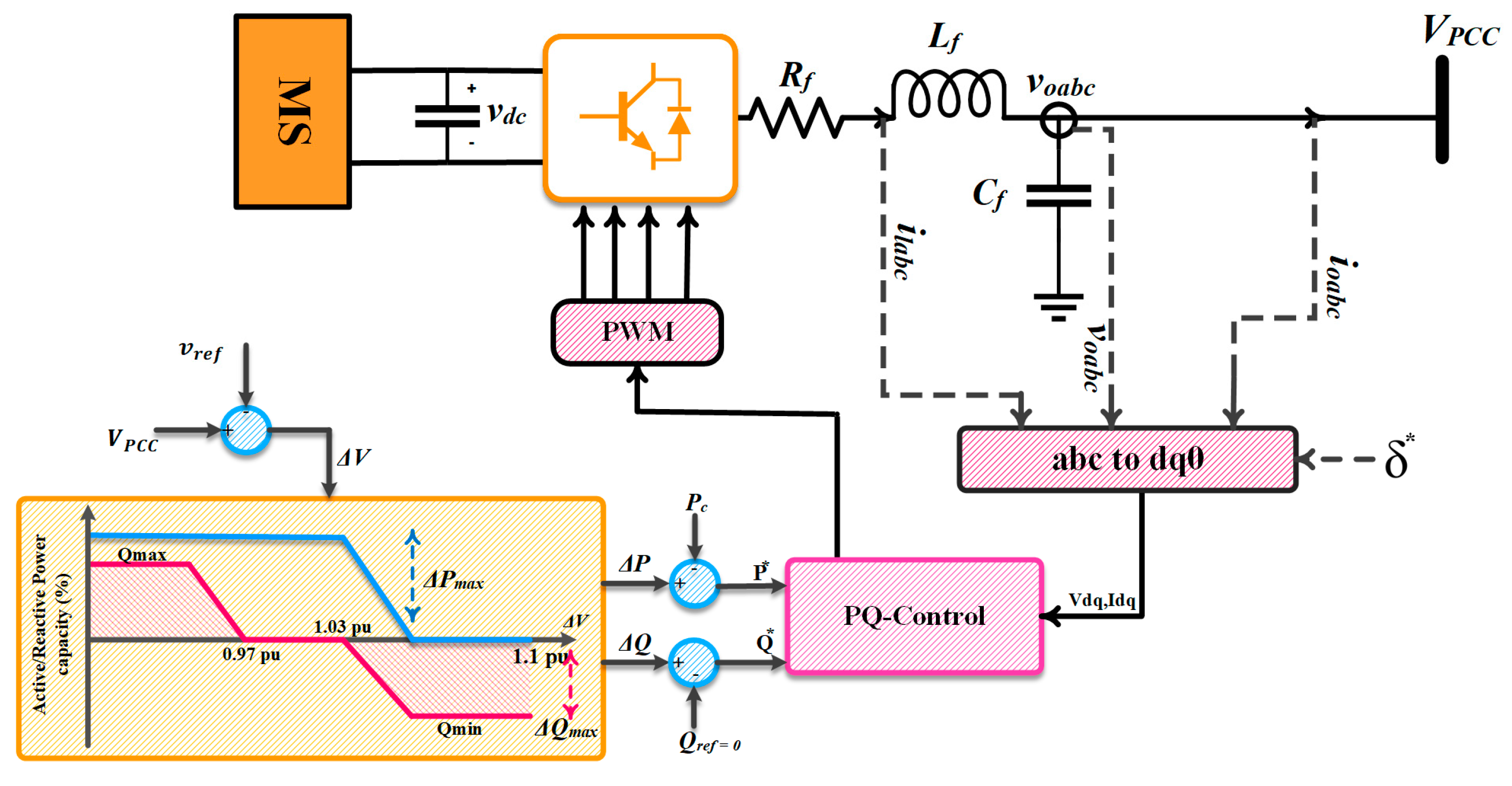
3.1.1. CVR through Smart Inverters

The smart inverter is a breakthrough technology for integrating DERs, specifically PVs and WTs, as well as BESSs, into modern grids with operational abilities beyond the inverters’ core functions [53,54]. A general overview of the smart inverters applications in modern grids covered by the IEC/TR 61850-90-7 document is listed in Table 2. Volt–var and volt-wattwatt management are the main applications of smart inverters for CVR implementation.
Precisely, with the previous consent of the grid operator, IIDGs were permitted to control voltage under the IEEE Standard 1547 by injecting or absorbing reactive power [56]. Thus, IIDGs can be used as controllable active and/or reactive power sources, and smart inverters can realize their voltage regulation capability. Specifically, the utilities typically restrict the penetration of large-scale PVs and WTs due to their negative effects, such as voltage rise in the distribution network. As a result, smart inverters’ primary application is to solve this problem by regulating the IIDG’s active/reactive power injection or absorption. Depending on the grid configuration, smart inverters may be used to modify the required active/reactive powers of residential-scale loads [57]. Precisely, the smart inverter follows the volt–var curve defined by the utility in the inductive network with a high X/R ratio, see Figure 5.
Hence, based on IIDG’s reactive power injection capacity, the VAr injection occurs in case of voltage drops (less than 0.97 pu) and VAr absorption occurs during the voltage rise (over 1.03 pu). On the other side, the smart inverter follows the defined volt-watt curve in the resistive network with a low X/R ratio and the IIDG’s rated active power mitigates during the voltage rise (over 1.03 pu). Note that costume volt–var and volt-watt curves are defined by the utilities for multiple purposes such as the CVR. The autonomous control mode of smart inverters tracks the volt–var and volt-watt curves for voltage regulation [58]. Additionally, smart inverters can regulate IIDG’s output power through the aggregated control mode, in which the smart inverter is controlled by a signal that is sent from a higher level of a control system or an algorithm [59]. Due to the effectiveness of smart inverters, CVR is utilized in both autonomous and aggregated modes by smart inverters in modern power systems [60,61,62].
Smart inverters can also be controlled by designing control rules through data-driven and machine-learning-based methods. Due to higher accuracy and precision when dealing with uncertain grids, machine learning and deep learning techniques have recently attracted a lot of interest [63,64,65,66,67]. Smart inverter-based CVR utilization requires high bandwidth communication links (HBWCL). These communication links are responsible for transmitting data such as referenced active/reactive power and voltage values as well as security signals between utility operators, smart inverters, and measuring equipment. Employing data-driven methods can significantly reduce the use of communication links. In light of this, in [68], a support vector machine is used to perform a multi-task learning algorithm aiming to control the smart inverter. More specifically multiple inverter rules are modeled as a non-linear function of local and/or remoter controllers. Hence, by considering the electric coupling among inverters, multiple training scenarios are employed to minimize the voltage deviation. Numerical tests of the proposed method using real-world data prove the efficiency of the machine learning methods in voltage control and regulation by smart inverters.
Sample CVR-based volt–var control strategy using a grid-forming structure is illustrated in Figure 6. In this structure, grid-forming IIDGs are utilized as voltage source inverters (VSCs), which measure the injected active and reactive power, aiming to regulate the output voltage and frequency according to the measured values. Meanwhile, the smart inverter performs as a current source while adjusting the voltage to perform the CVR through reactive power compensation. Mathematically, the voltage difference as the error signal is computed as follows:
Δ V   =   V PCC V ref
where V PCC and V ref is the point of common coupling voltage and the reference voltage magnitude, respectively. Thereby, by considering the volt–var and volt–watt curves, the referenced active and reactive power—as the input signals of the inner voltage and current controllers—can be driven as follows:
P * = Δ P   +   P c
Q * = Δ Q   +   Q ref
where Δ P and Δ Q are the computed active and reactive power alternation by volt–var/watt curve, respectively. In addition, P c is the measured curtailed power by considering the smart inverter’s operational limits shown in Figure 5b. In addition, Q ref is the reference reactive power which can be set to zero by the operator. It should be noted that Δ P is limited between zero and Δ P max and Δ Q is ranged between ± Δ Q max . To implement the CVR through the mentioned control strategy Δ Q can be obtained as Δ Q max to maximize the CVR impact and adjust the demanded powers in different time scales based on what the CVR application is. Further information on the grid-forming structure and also the inner local controllers of the IIDG can be found in [69].
To realize the CVR, transactive methods can also be used by smart inverters, with the primary goal of enhancing the grid’s economic and marketing aspects [70,71]. Specifically, CVR can handle both control and marketing challenges in modern grids by integrating economics and control in power networks and modifying voltage via sourcing/sinking reactive power. Further, CVR by smart inverters can occur through optimization problems and by defining multiple voltage ranges as the IIDG’s voltage regulating capability. The capability of the proposed approach to manage grid voltage and provide sufficient Energy-Savings is demonstrated by experimental results of deploying CVR on a real power distribution feeder in the Midwest of the United States using smart inverters [72]. Additionally, the integration of BESSs and smart inverters shows how effective CVR strategies can be in resolving economic issues in addition to energy conservation [73]. In general, utilizing the CVR through smart inverters has the added benefit of conserving energy as well as increasing inertia and primary frequency response. Nevertheless, the stability of the grid-connected inverters must be taken into account when connecting to weak grids with high impedance [74,75].

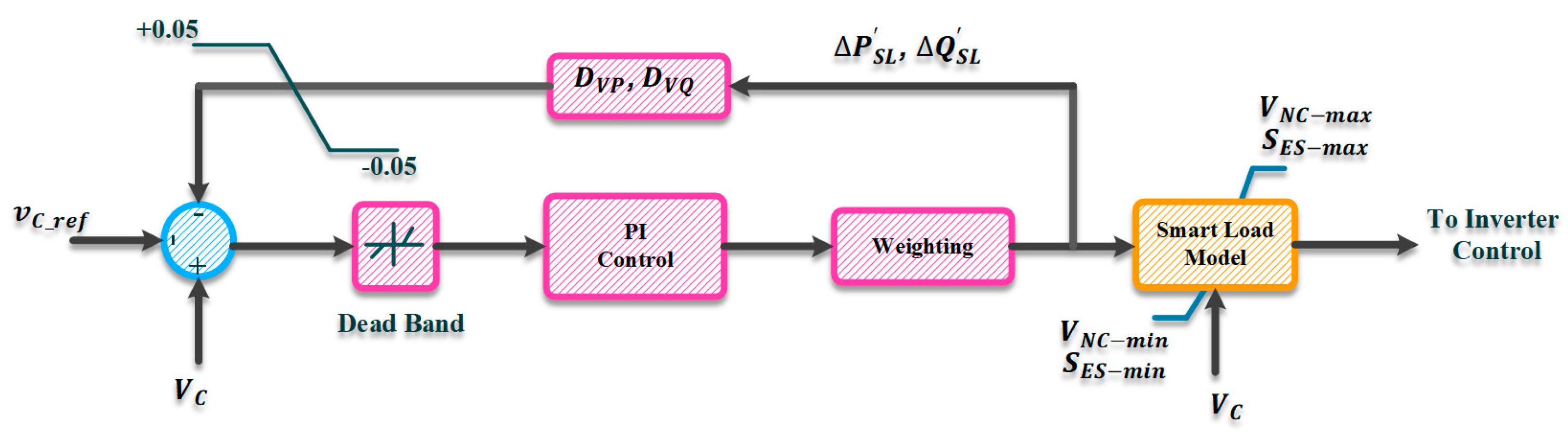
3.1.2. CVR through Smart Loads

SLs are PE-based equipment can be used to implement CVR by using voltage regulation capabilities to provide inertia synthesis and frequency support [76,77]. Modern PE-based grids use the voltage management capabilities of SLs to modify the required power consumption of large-scale loads to improve the grid’s transient and dynamic responses through CVR.
Electrical loads can be divided into critical (sensitive) and non-critical (NC) types, with the critical loads being unable to withstand a wide range of voltage alternations due to their requirement for uninterrupted, high-quality electricity. In contrast, power consumption in MGs supplying NC loads can be controlled by altering voltage with little to no effect on the consumer. SL is a voltage-dependent NC load connected to a voltage compensator (PE converter with a DC link) that can be employed to inject voltage with controlled magnitude and/or phase angle [78]. Specifically, the combination of voltage-dependent loads coupled with modern equipment, such as PE interfaced converters or electrical springs (ES), forms an SL compact that gives the capability of controlling load power consumption through CVR [79]. Note that an ES passes the RES’s fluctuations to NC loads by allowing their power consumption to vary [80].
Different configurations of SLs are possible, each with a unique ability to manage the required active/reactive power. The first approach to control the power consumption in an SL is to employ a series compensator (PE converter) between the load and the supply feeder, as shown in Figure 7a. This architecture performs as an SL with the ability to compensate only reactive power (commonly known as SLQ structure), which allows the terminal voltage and hence the SL’s output reactive power to be controlled by adjusting converter output voltage as follows:
V SL = V NC + V C
P SL = P NC
Q SL = Q NC ± Q C
where V SL ( V NC ), P SL ( P NC ), and Q SL ( Q NC ) are the SL’s (NC’s) output voltage and active and reactive powers, respectively. In addition, V C , and Q C are the compensator’s output voltage and reactive power, respectively. It should be pointed out that the DC compensator of an SLQ structure is a capacitor that limits the voltage phase angle (θES) to be adjusted (fixed at ± 90 ° ). As a result, the SL’s capability is constrained by this configuration, and it is unable to simultaneously regulate active and reactive powers. The SL can support and control the active power by including energy storage on the compensator’s DC link. This configuration is known as the SL with ES (commonly known as SLES) structure, which gives the θES to vary freely. However, there are concerns about the realization of SLES in power grids. For example, sophisticated control systems are required to manage the state of charge (SoC) of energy storage. Furthermore, due to the high penetration of RESs, the storage system is continually charging and discharging to deal with fluctuations that shorten the lifetime of the storage. Therefore, using a shunt back-to-back converter between the NC load and the supply feeder is an alternate method to adjust the SL’s output active and reactive powers simultaneously and independently of the grid’s X/R ratio. The construction of the SL with a B2B converter, often known as the SLBC, is depicted in Figure 7b.
This arrangement allows for the separate management of active and reactive powers since SLs can modify the voltage magnitude and phase angle. Thereby, the voltage alternation and reactive power consumption are similar to (7) and (9), respectively, and the active power consumption is as follows:
P SL = P NC ± P C
where Pc is the converter’s output active power. Precisely, in this structure, the first converter (converter 1) is responsible for adjusting the voltage magnitude and phase angle in a controlled manner. In the meantime, the second converter (converter 2) is responsible for maintaining the DC link’s voltage and supporting the active power exchanged by the first converter.
In PE-based grids, SLs are employed in a variety of topologies to regulate the frequency variations for the CVR application on frequency support and inertia synthesis. The inertia level is increased and the RoCoF is constrained, in particular, when the power balance is improved through voltage regulation of the SL’s output active/reactive power. As a result, the CVR and the SLs’ ability to control demand can accomplish the proper transient and dynamic stabilities. Figure 8 shows a sample SLBC voltage control system for CVR applications.
In this structure, voltage error ( Δ V ) is calculated by measuring the difference between the supply voltage (VC) and the reference voltage (Vref), and in the following level, Δ V is supplied to a proportional–integral (PI) controller. The output of the PI controller is weighted in accordance with the grid’s X/R ratio to modify the amount of alternate active ( Δ P SL ) and reactive ( Δ Q SL ) power consumption of SL that is required to determine the magnitude of the reference voltage (VES_ref) and phase angle ( θ ES _ ref ) of converter 2 in Figure 7b. In addition, allowable apparent power (SES-min and SES-max) and the change in NC load voltage (VNC-min and VNC-max) of the compensator are limited regarding the SL model. Additionally, the reference voltage (Vref) value is adjusted using the droop gains (DVP and DVQ) by taking into account the permissible limitations of ±0.05 p.u. to eliminate any potential interaction between the various SLs that might be connected in the grid [81].

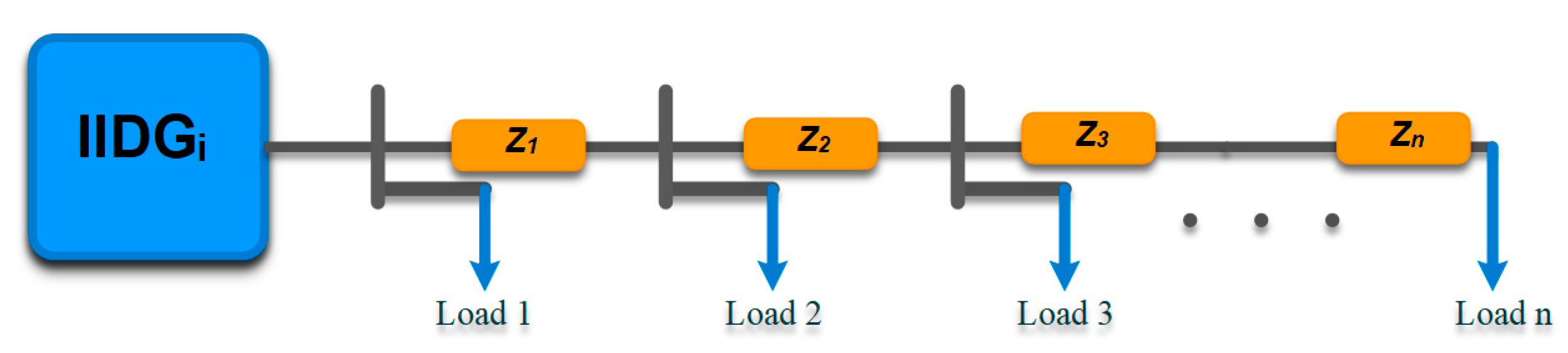
3.2. CVR Implementation in Islanded PE-Based MGs

CVR implementation in small-scale islanded MGs is realized through droop controllers [82]. To regulate voltage and frequency and manage the active/reactive power-sharing process among IIDGs, various types of droop schemes, including the conventional, modified, and adaptive types, are used in PE-based MGs [83]. Advanced voltage [84,85,86] and power control [87,88,89] methods are utilized in islanded PE-based MGs to develop droop-based CVR to enhance dynamic stability using frequency support techniques.

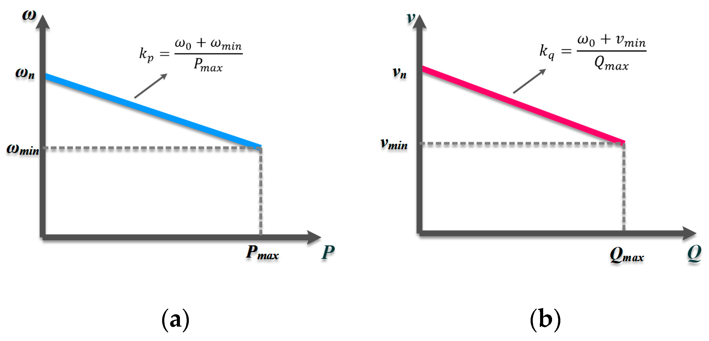
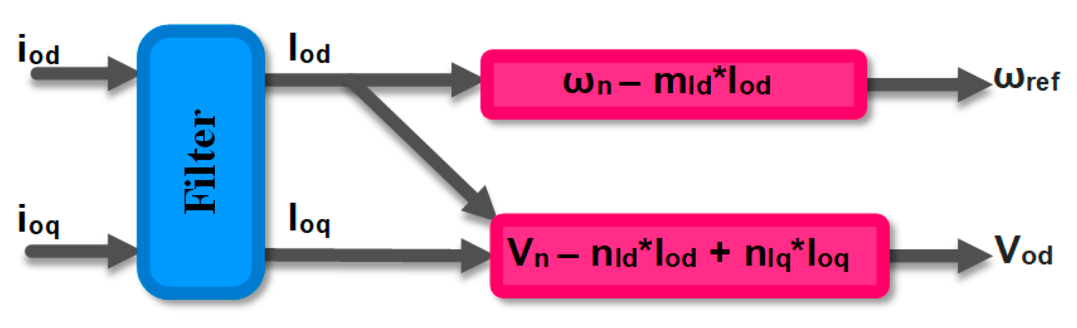
3.2.1. CVR Utilization through Conventional Droop Controllers

The P f and Q V (P-V and Q-f) droop loops in conventional droop controllers are in charge of controlling the voltage and frequency in an inductive (resistive) network with a high (low) X/R ratio while realizing power-sharing among IIDGs [90]. In an inductive grid ( X R and θ = 90 ° ), simplified power flow equations are as follows [91]:
P L = 1 x L v 0 v b sin ( δ )
Q L = 1 x L ( v 0 v b cos ( δ ) v b 2 )
where v 0 and v b are the source and load bus voltage, respectively. In addition, δ and cos ( θ ) are the power angle and power factor, respectively. Based on (10) and (11) and by obtaining the active and reactive power dependencies on frequency and voltage, the mathematical relationships of conventional droop loops, which are based on droop curves, shown in Figure 9, can be expressed as follows:
ω = ω n K p P
V = V n K q Q
where ω ( ω n ) and V ( V n ) are the operational (nominal) frequency and voltage, respectively. In addition, Kp and Kq are the P f and Q V droop coefficients, respectively. Note that a similar approach can be expressed for the resistive network as well.
In the described construction, CVR is employed in an inductive islanded MG consisting of IIDGs using the traditional droop-based approach [92]. As illustrated in Figure 10, the proposed technique activates CVR under peak and overload situations (Pmin < P < Pol and Qmin < Q < Qol) by adjusting the voltage level through the Q-V droop loop. The droop controller senses the peak demand and overload conditions by measuring the instantaneous voltage and frequency and basing its observations on the defined regions on droop curves.
Based on the overload conditions, mismatch active, reactive, and apparent powers are defined as follows:
Δ P = p ol p max
Δ Q = Q ol Q max
Δ S = Δ P 2 + Δ Q 2
Accordingly, the system activates CVR (CVR plus load shedding in high overload scenarios) as soon as the frequency and voltage thresholds are reached. It should be noted that load shedding supports the CVR during high overload situations and stabilizes MG operation. The voltage reduction amount is expressed as follows using Equations (15)–(17) as a basis.
Δ V = 0.5 Δ S V od
where V od is the direct-axis output voltage of the voltage source inverter (VSI) of IIDGs. Hence, the measured Δ V , is added to the Q-V droop loop as follows:
Δ Q = V min V ol Δ V K q
where V min is the threshold voltage value, indicating the overload conditions. In addition, V ol is the input signal of the local voltage controller which is responsible for controlling the direct and quadrature components of the VSI output voltage. The outcomes demonstrate the efficiency of the combined conventional droop-based CVR technique and load-shedding strategy in lowering energy consumption under peak demand and overload circumstances. The use of the CVR during overload and peak conditions leads to inertia synthesis and enhanced frequency response, which are significant outcomes of the study. Inertia synthesis and frequency support, however, are not directly specified as CVR goals in the suggested strategy. Joint dynamics [93] and transient [94] studies of CVR-droop control are required in autonomous MGs.

3.2.2. CVR Utilization through V-I Droop Controller

In the voltage–current (V-I) droop structure, the power-sharing process is simplified to the current sharing [95,96,97]. In this light, the main performance of the V-I droop-based CVR method in islanded MGs is determined by measuring the output current of each IIDG and by computing the overall line impedance along the feeder. Thus, the droop coefficient (ZT) which is the summation of the total line impedance, plays an essential role in implementing the CVR. Based on the IIDG model, depicted in Figure 11, the ZT extraction process is as follows:
Z T = i = 1 N Z n
However, the performance of this approach is questionable in a networked MG (with meth topology) as it is prone to high circulating current among IIDGS. The V-I droop structure restricts each IIDG’s output voltage by taking into account the IEEE standard, which makes sure that the voltage at each node is above 0.9 pu of the nominal voltage [98]. This calculation determines the overall line impedance along the feeder. Consequently, the V-I droop-based CVR’s mathematical relationship is as follows:
v T = 0.9     v n + I o     Z T
where v T , v n and I o are IIDG’s terminal voltage, nominal voltage, and the measured feedback current, respectively. The proposed approach in (21) is then added to the local controllers of the IIDG as the input signal of the outer loop voltage controller. Precisely, based on the proposed approach, the relationships of the direct and quadrature inputs of the local voltage controller are as follows:
{ v od = v T v oq = 0
The enhanced dynamic response by the V-I droop-based CVR structure reveals quicker recovery time in the event of a failure. Particularly, simulation results reveal a faster fault clearness time as compared to other droop structure types, such as the adaptive droop control scheme. However, the V-I droop-based CVR technique has a set of specific flaws. For instance, the accurate active reactive power-sharing is not considered comprehensively, since the input signal of the local voltage controller is limited to the MG configurations and line impedances. Thus, there would be no accurate control of IIDG’s power allocation, making accurate power-sharing hard to achieve. Moreover, the V-I droop is not a suitable solution for implementing CVR in MGs with meshed topology, since an IIDG may encounter different line impedances to a given load, and the line impedance computation isn’t precise.

3.2.3. CVR Utilization through the Current Droop Controller

Modified droop controllers are widely adopted in MGs to overcome the limitations of the conventional droop and drawbacks, such as inaccurate reactive power-sharing [99,100,101]. The current droop-based controller is a modified droop structure that is proposed aiming to implement CVR in an islanded MG [102]. The current droop controller’s main purpose is to achieve a faster IIDG response to load demand variations. Therefore, multiple current-based droop loops are in charge of power-sharing and the CVR process simultaneously by utilizing the park transformation and extracting the I o d and I o q from the inverter’s output current feedback, as shown in Figure 12. Specifically, the I d V droop loop controls the CVR action, and meanwhile, I d ω and the I q V droop loops are responsible for active/reactive power-sharing among IIDGs. In addition, the CVR’s imposed voltage reduction amount, which is set equal for all IIDGs, is obtained by adjusting the droop coefficients as follows:
Δ V D C V R = n I d 1 I o d 1 = = n I d i I o d i = = n I d n I o d n
where n I d i is the related CVR droop gain of the i t h IIDG. The V-I droop-based CVR method achieved enhanced frequency response and inertia synthesis, just as other droop-based CVR systems of this type. Additionally, the small-signal stability analysis simulation findings demonstrate that the current droop-based CVR exhibits greater system damping than traditional droop controllers, which improves the stability and reliability of the MG. Like the other droop-based CVR techniques, an important outcome of the V-I droop-based CVR approach is frequency support and inertia synthesis which is not pointed out in the presented study. Detailed information on the different droop controllers alongside the IIDGs’ local controllers can be found in [103] for interested readers.

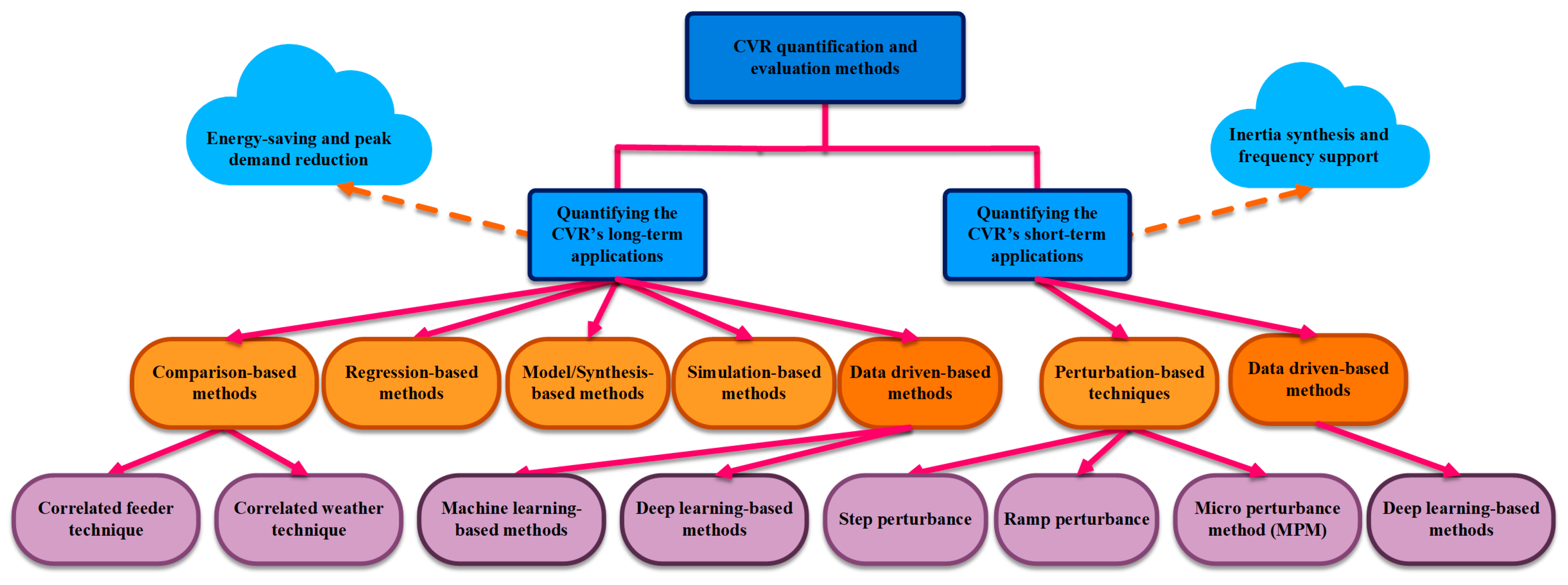
4. Quantifying CVR Impacts on Modern Grids

CVR applications in PE-based modern grids should be quantified to represent and evaluate the CVR impacts on voltage, frequency, and demanded active/reactive power. In addition, proposing a benchmark for comparing CVR impacts, enhances the system’s accuracy in selecting the target feeder to maximize voltage reduction amount and consequently maximize the CVR benefits. Classifying the CVR quantification methods based on the CVR application can intensely improve the evaluation methods in terms of finding the proper method, tools, and equipment. Thereby, the overall perspective of the application-based classification of CVR quantification techniques is depicted in Figure 13.

4.1. Quantifying the CVR’s Long-Term Applications

CVR factor is commonly used to quantify the long-term CVR applications and can be expressed for active/reactive power as follows [104]:
CVR f ,   P = % Δ P % Δ V = % ( P post P pre P mean ) × 100 % ( V post V pre ) / V mean × 100
CVR f ,   Q = % Δ Q % Δ V = % ( Q post Q pre Q mean ) × 100 % ( V post V pre ) / V mean × 100
where V post ( V pre ), P post ( P pre ), and Q post ( Q pre ) are the measured values of voltage, active and reactive powers, after (before) CVR adjustment, respectively. In addition, V mean , P mean , and Q mean are the mean values of voltage, active, and reactive powers, respectively.
Several CVR-factor derivation techniques concentrate on steady-state time scales that quantify the CVR’s long-term applications, such as energy saving. The following categories apply to these techniques.
  • comparison-based methods;
  • regression-based methods;
  • model/synthesis-based methods;
  • simulation-based methods;
  • data-driven-based methods.

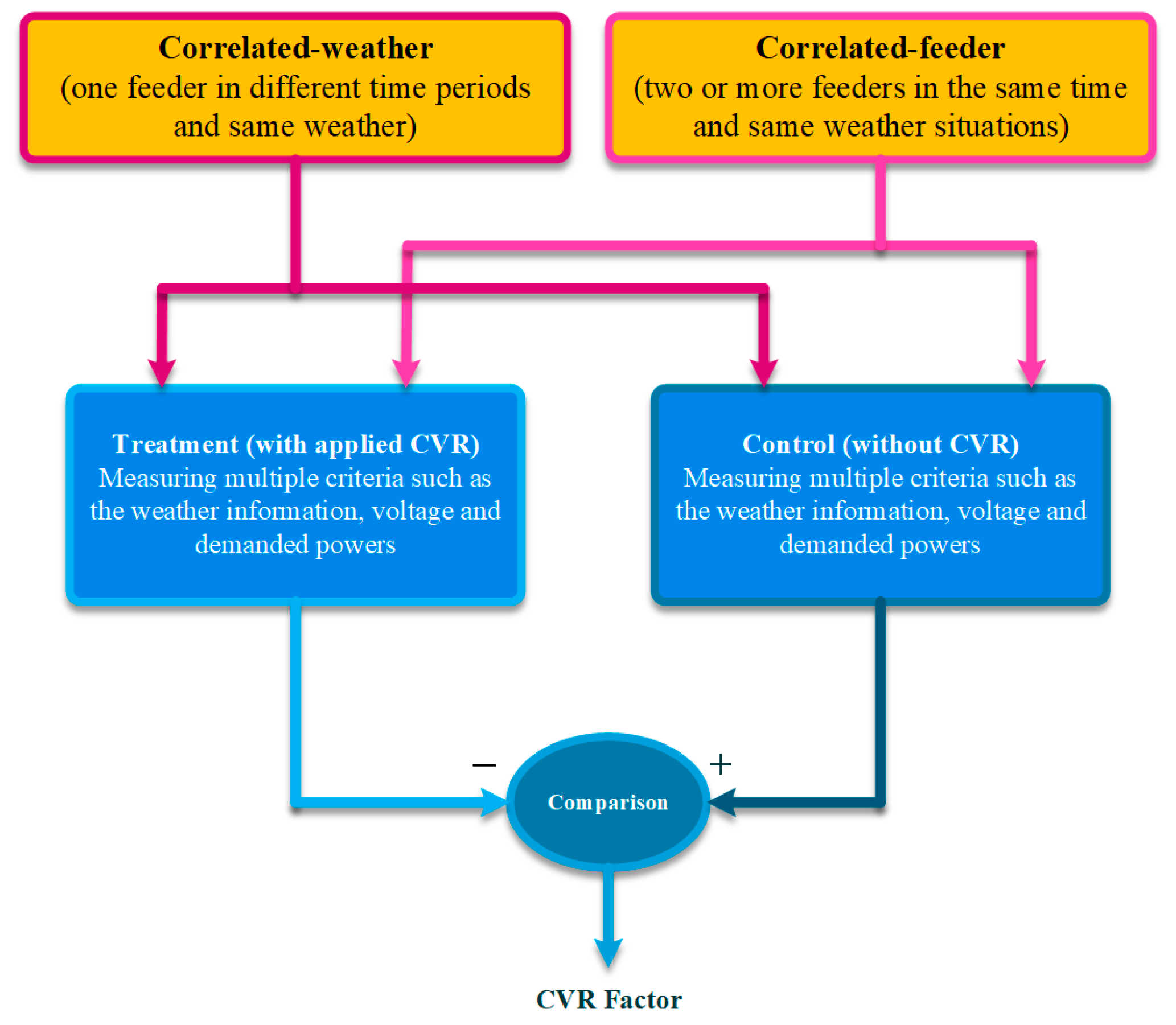
4.1.1. Comparison-Based Methods

The basis of comparison-based approaches is quantifying the behavior of the grid in CVR on/off states. In order to determine the CVR factor, operational data on a chosen target feeder are extracted in both the absence and presence of the CVR [105,106]. Two separate approaches—correlated feeder and correlated weather conditions—are used to establish the CVR factor through comparison-based methodologies, as shown in Figure 14 [107].
In the correlated feeder approach, the operation of two or more feeders is compared in different conditions. Specifically, one feeder (commonly referred to as a treatment feeder) is examined in a CVR-on circumstance, while another is evaluated in a CVR-off situation (commonly known as a control feeder). In order to compare the treatment and control feeders, multiple data sets including voltage-demanded power, and weather information is extracted via observatory systems such as SCADA. Treatment and control feeders should be correlated to each other in terms of the topology configurations, feeder characteristics, loading conditions, power factor, and their locations (being adjacent to each other). Finding the same feeders that are highly correlated to one another is therefore quite difficult. To address this issue, feeders with the highest correlation rate (coefficient) are found using correlation analysis, also known as the Pearson product–moment correlation coefficient [108]. The Pearson product–moment correlation coefficient for sample variables of X and Y is defined as follows:
corr = cov ( X , Y ) σ X σ Y = E ( XY ) E ( X 2 ) E ( X ) 2 E ( Y 2 ) E ( Y ) 2
where cov , σ X , σ Y and E are the covariance function, standard deviations of X, Y, and the expected value operator, respectively. The value of corr ranges from −1 to +1, with −1 and +1 both denoting a high correlation between X and Y. However, the coefficients of zero and close to zero signify weak relationships.
On the other side, one feeder’s performance is compared in CVR-on and CVR-off scenarios using the correlated weather approach. Specifically, after applying CVR to the feeder (treatment feeder), the regular voltage was supplied to the feeder at a later time and in the same weather (control feeder). As a result, the operation of a feeder is assessed under various circumstances, and the CVR factor is determined by comparing the measured data. Specifically, the CVR factor is obtained to quantify the CVR impacts by comparing the voltage and energy-saving amount in different scenarios. This is true for both the correlated feeder and correlated weather approaches. Although the comparison-based approaches are simple to apply, there are technical challenges that lead to inaccurate CVR quantification. For instance, a significant issue that may disguise the CVR effect and therefore lead to inaccurate CVR factor calculation is additional data noise, which is the ensuing impact of the measuring equipment.

4.1.2. Regression-Based Methods

Regression-based techniques are based on the load modeling type and their impact on the CVR effect [109]. In the regression-based approaches, loads are modeled and estimated based on different criteria such as temperature, humidity, voltage, and solar intensity through the regression process. Meanwhile, the CVR factor is calculated by comparing the load model’s output data in the presence and absence of the CVR.
Linear regression can be employed to calculate the CVR factor, and its process happens in multiple stages. At the first stage and by considering the load temperature as the only load-dependent criteria, the load model parameters can be extracted as follows:
L ( MW ) = β 0 1 + β 1 [ T fh 1 T ] + β 2 [ T fc 1 T ] + ε
where L and T are the measured load data and ambient temperature in the CVR-off situation, respectively. In addition, T fh and T fc are the referenced heating and cooling temperatures, respectively. Further, β 0 , β 1 , and β 2 are the regressor’s coefficients and ε represents the error. The regressor’s coefficients are calculated and estimated using the least square method as follows:
β ^ = [ β 0 ^   β 1 ^   β 2 ^ ] T = ( X T X ) 1 X T L
X = [ 1 T fh 1 TT fc 1 T ]
Based on the estimated parameters of Equation (29), the load data (power consumption) is calculated for the new temperature ( T * ) as follows:
L CVR _ off = β 0 ^ 1 + β 1 ^ [ T fh 1 T * ] + β 2 ^ [ T fc 1 T * ]
where L * is the load-measured data in absence of the CVR. On the other side, L CVR _ on , which represents the load data during the presence of the CVR, is directly calculated from the feeder. Finally, the CVR factor can be calculated as follows:
CVR f = % Δ L % Δ V
% Δ L = L CVR _ off L CVR _ on L CVR _ off 100
In the prior method, the load is represented as a temperature function using linear regression. The linear regression can be illustrated by taking into account the voltage in addition to the temperature as follows [110,111]:
L ( MW ) = α 0 1 + α 1 T + α 2 V + ε
where α 1 and α 2 are the load-to-temperature and load-to-voltage dependencies, respectively. likewise, as in Equations (28)–(32), the CVR factor can be derived using the value of α 2 . Regression is used to calculate the CVR factor at the California Public Utilities Commission, and the results indicate that multivariate regression can provide more accurate results when additional criteria, such as the day of the week and the month, are taken into account in addition to temperature and voltage. Although linear regression-based techniques are more accurate than comparison-based approaches, the estimation errors during the regression process still are a technical barrier that blurs the CVR effect and consequently decreases its functionality. Another technical barrier is employing linear regression on non-linear loads since the nature of these techniques and their characteristics are linear. Machine learning-based regression techniques that are more exact and sophisticated are therefore suggested in the literature.

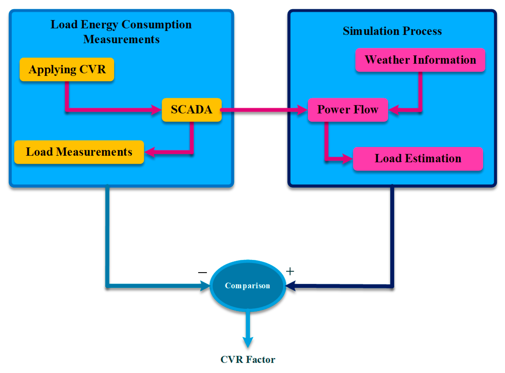
4.1.3. Model/Synthesis-Based Methods

Synthesis-based methods estimate the CVR effect based on LTV behaviors [112,113,114]. The LTV aggregation methods can be divided into a synthesis of load components (component-based synthesis) and synthesis from customers (customer-based synthesis). In the component-based techniques, the electric load appliances are modeled as a voltage function and the total energy consumption is computed as follows:
E T ( v ) = i E i ( v ) S i
where E i ( v ) is the energy consumption of the customer’s appliance i at voltage v and S i is the demand share coefficient that represents each appliance’s energy consumption level of the total energy consumption. Thus, the CVR factor is determined by computing the total energy consumption in two alternative scenarios (with/without CVR). In contrast, consumers in customer-based synthesis are classified as either residential (R), commercial (c), or industrial (I). This distinction is made since, compared to industrial loads, commercial and residential customers have higher voltage dependencies, hence lowering voltage results in higher levels of energy savings for them. Thus, by dividing customers into different classes the CVR factor is calculated as follows:
CVR f = R CVR f , R + C CVR f , c + I CVR f , I
where R ( CVR f , R ), C( CVR f , C ), and I( CVR f , I ) are the CVR factor coefficients representing the load share (CVR factors) of the residential, commercial, and industrial customer classes, respectively. The CVR effect can be quickly quantified before being applied to the chosen feeders using synthesis-based methods. However, it is challenging to obtain accurate load-sharing coefficients, data, and LTV responses for every electric appliance.
As an example of the model-based quantification method, a robust time-varying load modeling strategy is indicated by [16] to address the intermittency of renewable generators, which causes the load model parameters to change rapidly. The robust recursive least squares approach is employed in the ZIP load model time-varying parameters and the proposed framework is able to track the continuous and sudden changes in load parameters. Additionally, there are no prerequisites for linear correlations between the load and its impact parameters, which improves the effectiveness of CVR evaluation.

4.1.4. Simulation-Based Methods

In simulation-based methods, the load energy consumption is modeled and estimated considering that CVR is not enabled. More specifically, based on the grid’s configuration and power flow equations, loads are modeled as a function of the voltage, time, and weather. In simulation-based approaches, the CVR factor is calculated by comparing the differences between power flow calculations and the measured demanded energy consumption, as shown in Figure 15. In the simulation process, the demand for the target feeder is calculated using real-time power flow equations without considering the CVR effect, and the demand for the experimental feeder is computed by considering the CVR effect and through observatory systems such as SCADA.
The major benefit of the simulation-based structure is its high accuracy and precision in the case of employing detailed load models and grid configuration information. However, a challenge to this approach is to select a proper load model (i.e., ZIP or open-/closed-loop load models) in order to present an accurate model contributing to the CVR and energy-saving effects. Moreover, building models for all existing load components may be hard to achieve which makes the simulation process complex.

4.1.5. Data-Driven Based Methods (Long-Term Applications)

Data-driven quantification techniques—including machine learning- and deep learning-based ones—are convenient approaches to evaluate the CVR impacts in complex PE-based grid configurations. Data-driven techniques can be employed as a solution to the challenges of classic methods, which can be listed as follows [115]:
  • Finding correlated feeders with similar load profiles to perform the CVR evaluation needs high-precision techniques to prevent inaccurate CVR factor calculation. Specifically, finding correlated feeders where CVR is performed on a great number of feeders is a critical issue that makes classic techniques inapplicable.
  • Estimating the load profile including the demanded active/reactive power while having CVR disabled, is another important challenge that leads to inaccurate CVR factor calculation via classic techniques.
  • Data anomalies are another vital issue of CVR quantification through classic techniques. Precisely, applying the classic methods on real PE-based grids shows a divergence from the results of using the original practical data.
As a result, utilizing machine learning- and deep learning-based models can be a straightforward solution to quantify the CVR’s long-term applications. These techniques produce more accurate and precise results which can also handle the non-linear and complex interactions between the load models and their impact variables.

Machine Learning-Based Methods

Multiple machine learning-based methods using different supervised and unsupervised models including support vector machines (SVMs), gradient boosting machines (GBMs), and k-means are proposed in the literature to assess the CVR impacts [116]. These techniques mainly focus on the similarity load and data profile issues in classic techniques.
SVMs are supervised machine learning models with related learning algorithms used for classification and regression analysis [117,118,119]. An SVM generates a hyperplane or group of hyper-planes in a high- or infinite-dimensional space that can be used for classification, and regression. The SVM’s performance is based on setting a maximum margin for a linear classifier and employing the “kernel trick” method to extend up a linear classifier to a non-linear classifier (see Figure 16). Thereby, using SVMs can efficiently quantify the CVR impacts dealing with non-linear and complex structures of PE-based grids.
SVM-based regression approaches are used in the literature to evaluate the CVR by estimating the load profiles and consequently calculating the CVR factor [120,121,122]. These techniques transfer the input data to a higher dimensional feature space, which identifies a non-linear map from the input space to the output space. Specifically, the load profile is estimated while CVR is disabled using the multi-stage SVM (MSVM). Thereby, as shown in Figure 17, a three-stage SVM-based quantification approach can be proposed in which the first stage is responsible for selecting similar load profiles by calculating the demanded active power with and without the CVR impact. Specifically, pre- and post-CVR data are acquired in the first stage to determine the Euclidian distance index and then a series of load profiles are chosen using the driven index. In the second stage, selected profiles are used to train the SVR model and then test results are employed to estimate the load profiles while having CVR off. To assess the proper performance of the proposed model, the MSVM is compared with multi-linear regression using a practical dataset of historic load information. Thereby, mean absolute percentage error (MAPE) is employed as follows to calculate the test error:
MAPE = 1 n i = 1 n | P A , i P f , i P A , i |
where n is the total number of test days. Further P A , i and P f , i are the actual and estimated demanded active power, respectively. Finally, the target MSVM model with a result test error of less than 0.8 percent is used to calculate the CVR factor and subsequently quantify the CVR impacts.
The GBM technique is another machine learning model employed to evaluate the CVR long-term applications by estimating the load profile and creating a CVR baseline [123]. Note that the CVR baseline is the load profile while the CVR is disabled. Likewise, SVM-based method, the basic methodology is focused on similarity-based techniques. However, the chosen load profile is selected as the load power and temperature, making the presented approach more accurate. Then, a bidirectional GBM is employed which significantly increases the system’s accuracy in creating a CVR baseline. Specifically, the proposed algorithm is applied to the grid through two main stages. In the first stage, similar load profiles are selected based on the pre and post-CVR data from the historic data in target test days. In the second stage and based on the collected data, the iterative bidirectional backward and forward GBMs are trained. In each iteration, two generated CVR baselines are compared and reconciled. Thereby, the input for the following iteration is limited to the first and last points on the reconciled baseline. The iteration repeats until all CVR baseline points are generated. Finally, the CVR factor is driven using the estimated baselines.
Further, the k-means method as another machine learning-based model is employed to evaluate the CVR impacts [124]. Unlike the previous methods, the k-means is an unsupervised algorithm that set multiple clusters based on the similarity in cluster specifications (see Figure 18) [125]. The presented approach is also focused on finding similar and correlated feeders. The suggested approach is used as a means of quantifying the CVR in a grid where the CVR is applied to numerous feeders.
The k-mans-based quantification technique is utilized through two stages. In the first stage, to reduce the complexity of managing the operating schedules, random feeders are chosen from a large number of feeders. Therefore, random sampling is driven to choose the smallest number of feeders as follows:
n = Z 2 CV 2 RE 2
where n is the sample size, z is the normal standard z-score corresponding to the desired confidence level, RE is the desired relative error, and CV is the coefficient of variation. Then, in the second stage, the k-mean is applied to cluster the total feeders based on the similarities in location and connected load profiles. Finally, the CVR factor calculation is applied to target clusters to quantify the CVR impacts. The simulation results indicate that employing an unsupervised k-means model for clustering the feeders significantly reduces the complexity of CVR factor calculation which also increases the accuracy of the final results.

Deep Learning-Based Methods

Machine learning-based quantification methods which commonly perform as similarity-based techniques are straightforward to implement. However, their accuracy needs more investigation since the similarity metrics (e.g., weather, load types, or feeder locations) are defined by the operator, which makes the method accuracy dependent on the mentioned metrics. In this light, deep learning-based approaches using deep neural networks (DNNs) are proposed in the literature that are mainly generative-based techniques [126]. Specifically, these methods focus on restoring and generating the load behavior without the CVR impact after/while the CVR is applied to the feeders.
The author in [127] proposed a generative adversarial net (GAN) based Load profile inpainting network that can be used as a CVR baseline producer. As shown in Figure 19, the proposed GAN network consists of a fully connected layer generator and discriminator networks. The inputs of the generator network are masked load and temperature profiles which are used to generate the G(z). Therefore, the generator which is a deep convolutional network tries to fool the discriminator by creating fake data of G(z). On the other side, the discriminator which is constructed by a gated convolutional network is responsible for distinguishing G(z) from the real data of x by assigning greater probabilities to x. Finally, the trained GAN is capable of generating the original load profile without the CVR impact.
To assess its performance on the CVR load generation during the CVR off situations the problem formulation is utilized as follows:
CVR net i = CVR raw i + bias
where CVR net i and CVR raw i are the average normalized load reduction amount of the ith CVR event with and without considering the bias load, respectively. Further bias is the criteria for showing whether the model has a consistent difference between the actual and the generated data. Precisely, the bias is aimed to be forecasted according to the outputs of the trained GAN network. Finally, the CVR factor is calculated as follows:
CVR f = 1 N CVR i = 1 N CVR CVR net i Δ V i
where N CVR is the total number of CVR events and Δ V i is the voltage reduction amount in the ith CVR event. The proposed DNN-based model is tested on a real feeder in North Carolina, USA. For each feeder, the non-CVR test days are used to train the GAN network and finally the trained model is used to test the load estimation while applying CVR. The practical result shows accurate CVR quantification with a minimum error rate in comparison with utilizing the actual data to calculate the CVR factor.

4.2. Quantifying the CVR’s Short-Term Applications

As transients/dynamic stability in modern grids is improved through short-term applications of the CVR (i.e., inertia synthesis and frequency support), quantifying CVR impacts during mentioned time scales is not possible by using traditional quantification techniques with the high penetration of IIDGs. Critical issues and challenges of applying conventional techniques for evaluating CVR short-term applications are listed as follows:
  • A critical issue is with the natural fluctuations of the inverter-interfaced suppliers’ impact in PE-based grids on voltage profile, which distorts the CVR effects. The fast response of the PE-based suppliers and consumers (i.e., IIDGs, and SLs) needs real-time quantification methods. However, the traditional quantification methods are unable to track the CVR impact continuously and in real-time.
  • Further, since all of the traditional quantification techniques outlined in the preceding sections are focused on steady states, they are unable to quantify and follow the effect of CVR on transients and dynamics. Alternative techniques are therefore required to fully quantify and assess the CVR across all time scales.
  • Moreover, distinguishing between the load’s change behavior and the data noise during the transients and dynamics becomes bold. In light of this, a suitable noise reduction methodology, not covered by the other methods, is urgently required for estimating CVR in modern PE-based grids.
Thereby, alternative quantification methods are proposed aiming to address the aforementioned difficulties and problems.

4.2.1. Perturbation-Based Techniques

Perturbation-based approaches are online CVR evaluation frameworks that measure CVR-related load and voltage data in real time to evaluate CVR effects [128,129,130,131,132]. Thus, for quantifying the needed data in a continuous manner, proactive voltage perturbation schemes are employed. The perturbation induces the CVR effect; meanwhile, the CVR factor is continuously calculated through experimental data. Note that various perturbation-based quantification approaches utilize various perturbation signals, noise reduction strategies, and CVR quantification indices. Table 3 displays a comparison of various perturbation-based architectures.

Step and Ramp Perturbance-Based Techniques

The studies in [129,131] present step perturbance-based techniques in which the step voltage signal is injected into the control system via a clamp-on voltage injection device to induce the CVR impact. In the first stage, a small (0.5% to 1%) voltage is added to the target feeder voltage where the CVR is applied. Thereby, the corresponding change in power is measured to calculate the CVR factor. The clamp-on device has a single-turn transformer and a silicon-controlled rectifier (SCR)-based PE circuit to control the injected voltage. The primary side is connected in series with the distribution power plant and the secondary is connected to the voltage source. The SCR-based circuit injects the voltage in buck mode that induces the CVR by the negative voltage injection. Further, in ramp perturbation-based quantification techniques the CVR is induced by a ramp signal, in which the basic methodology of evaluating the CVR impact is by calculating the CVR factor [128]. Both step- and ramp-based techniques employ the noise reduction method to remove the local noise which is produced by multiple pieces of equipment on the target feeder where CVR is utilized. The step-based method tends to reduce the local noise by using a robust regression method. Further, the ramp-based technique uses custom noise reduction which is utilized based on formulating the standard load power variation to the CVR. However, there are technical barriers to the step and ramp perturbance-based techniques that make the proposed methods incarcerate and vulnerable to the system configuration on quantifying the short-term applications. These barriers can be listed as follows:
  • The proposed noise reduction approaches are unstable which makes the CVR factor underestimated or overestimated in heavy noise situations.
  • The present method focuses on only CVR factor calculation which is commonly used for steady-sate operations. This can pose a barrier to the accuracy of the proposed techniques.
In order to overcome the mentioned issue and enhance perturbation-based strategies for measuring the CVR during dynamics, an improved online CVR assessment method is provided in [130,132].

Micro Perturbance-Based Techniques

The accurate real-time CVR quantification for assessing the CVR impact on dynamic responses is through the micro perturbation-based method (MPM) which is realized by using smart transformers (STs). Since load sensitivity identification is a critical challenge in online CVR assessment methodologies, minor load power fluctuations caused by voltage and frequency variations should be precisely monitored to aid in CVR measurement. The use of STs is a frequent approach in MPM for achieving precise load sensitivity identification. STs are a type of solid-state transformer that can regulate the voltage and frequency on both the LV and MV sides separately [133,134,135,136,137,138]. To avoid overload conditions, STs can provide additional grid services such as voltage regulation and equalization. Figure 20 depicts a sample control structure of an ST. The DC/DC converter in this structure is in charge of converting voltage from low voltage (LV) to medium voltage (MV), as well as managing the DC link voltage, which keeps the input and output active powers balanced. The referenced active power is constrained by the ST rating between Pmax and Pmin which are determined by the ST rating. The LV converter is controlled through voltage and current control loops for keeping the voltage and frequency constant under any loading conditions. In addition, the MV side’s converter controls reactive power injection on the MV side. Although ST normally functions with a constant power factor by setting the referenced reactive power (Q*) to zero, in the event of voltage support, it can generate reactive power.
Note that the reactive power reference in an inverter-based MG can be set by the Q/V droop controller. The referenced LV side’s voltage magnitude is determined by the load identification block, which is also in charge of using the STs to identify any changes in the load. Precisely, the micro perturbation is applied to the voltage or frequency through the identification block, and meanwhile, active/reactive power consumption is measured to calculate the voltage/frequency load sensitivity coefficients as follows:
N p = Δ P / P 0 Δ V / V 0
N q = Δ Q / Q 0 Δ V / v 0
where P0, Q0, and V0 are the active and reactive powers and RMS voltages, respectively. In addition, Δ P , Δ Q , and Δ v are the active and reactive power variations during the perturbation, respectively.
Based on the MPM analysis, the provided structure extracts the CVR-related load and voltage data. The pseudo-random-binary-sequence (PRBS), which serves as a micro-perturbation signal, continually excites the CVR process in order to continuously quantify the CVR effect. Additionally, the LTV’s transfer function and the CVR factor are both used to measure the impact of the CVR on both the dynamic and steady states. The cross-correlation identification approach is also used to address various CVR application requirements, which has significantly increased the ability of noise reduction when compared to the other perturbation-based techniques. Furthermore, hardware-in-the-loop (HIL), where the dynamic process of the CVR effect is thoroughly evaluated, is used to quantify the effectiveness of the CVR. In comparison to other perturbation-based procedures, MPM is the most accurate quantification method, since it can continuously quantify the CVR effect throughout any timescale, including transients and dynamics. However, the requirement for cutting-edge electrical equipment and control systems, makes their structure complicated and expensive, which poses a barrier to these procedures.

4.2.2. Data-Driven Based Techniques (Short-Term Applications)
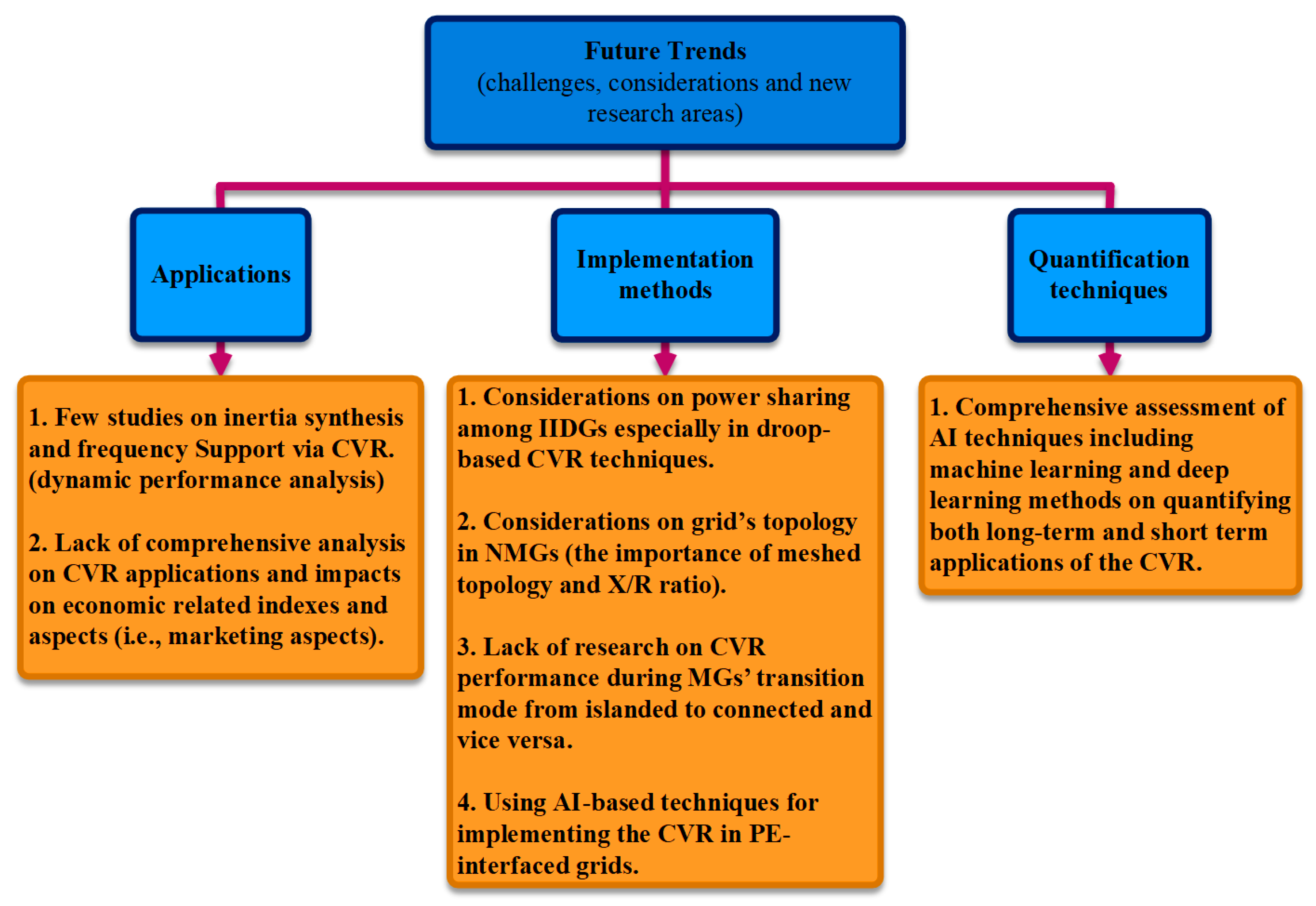
Data-driven methods in quantifying the short-term CVR applications are focused on DNN-based algorithms that show high accuracy in evaluating the CVR impacts [139,140]. In light of this, a DNN model with a backpropagation training algorithm is proposed in [139] to analyze the behavior of the CVR and its effects on the target feeder. As shown in Figure 21, in a backpropagation-based DNN algorithm the DNN forwards the received inputs and associates them with weights and biases to produce the output. Then, in an iterative scheme, the DNN is trained with a supervised learning approach, in which the difference between the system’s output and a known predicted output as an error is supplied to the training algorithm. Thereby, the weights are updated to minimize the global error driven in each iteration according to the updated weights in a forward and backward algorithm.
In the proposed DNN-based quantification technique the model is trained through the Levenberg–Marquardt training method which considers day, hour, and whether information as the load profile inputs. The proposed model predicts load savings and creates a CVR baseline. Unlike the similarity-based techniques, the DNN acts as a generative-based scheme to estimate the output load saving. Thereby, the method accuracy is highly increased, making the proposed model a precise quantification technique. In this scheme, the dynamic load behavior can be tracked by the proposed technique which makes the model capable of evaluating the short-term applications of the CVR. The practical result on multiple substations in Washington EMC utility shows high accuracy with 0.22% error in tracking and generating the load during the dynamics change load behavior by the CVR.
Further, another DNN-based technique with a similar approach is also presented in [140] which is utilized for both CVR and power loss studies. The DNN model inputs are active and reactive powers and also the voltage in the target feeder where CVR is applied. The input data for training the DNN are gathered via the measurement equipment on substations. The DNN output is the simulated active power that can be compared to the real value to quantify the CVR impacts. The simulation results on the IEEE 13-bus and 34-bus systems show the high accuracy of the presented model to evaluate the CVR.

5. Future Trends

Based on the review presented in this work on the CVR applications, implementation methods, and quantification approaches in PE-based modern grids, the future trends to fill the existing gaps and research directions are briefly summarized as follows, see Figure 22.

5.1. Future Trends on CVR Applications

As the CVR utilization in PE-based grids covers various applications, by filling the existing gaps in the future trend, CVR can ultimately improve the stability and economic efficiency of modern grids. Thereby, the future trend in this part can be divided as follows:
Inertia synthesis and frequency support via CVR: The most crucial aspects of the CVR applications are inertia synthesis and dynamics frequency support in PE-based power systems, particularly in grids with a high penetration of IIDGs. Despite the effort on this issue (e.g., using SLs), more investigation is required to analyze the impact of CVR on grid inertia for improving dynamic stability and providing frequency support. For instance, droop-based CVR methodologies only focused on peak-demand reduction and energy-saving, and dynamic performance analysis has not elaborated on.
The economic aspect of the CVR: Economic issues with power systems are a critical concern as a result of the energy crisis, and they are becoming more challenging in modern power systems with the presence of RESs. Only a few works have examined the economic benefits of CVR in modern grids, even though it can be a solution from an economic point of view. Therefore, additional analyses are required to fully examine and utilize the CVR as an effective solution. Notably, the CVR impacts on economic-related subjects, such as electricity marketing, need to be considered. For instance, to achieve CVR, the smart inverters in grid-connected MGs provide a portion of their capacity to absorb reactive power. Therefore, additional research is needed to determine the market pricing of this service to encourage stakeholders to take part in the program.

5.2. Future Trends on CVR Implementation

Although different advanced equipment is employed to implement the CVR in PE-based grids, there are technical barriers that need further assessment to improve the CVR performance. Hence, the future trend of the CVR implementation methods can be discussed as follows:
Power-sharing: Power-sharing is a technical obstacle to implementing the CVR, particularly with droop-based techniques, that requires further research. The proposed droop-based CVR approaches lack a sufficient power allocation strategy, which affects both the local controllers (i.e., local current and voltage controllers of an IIDG) and CVR’s functionality. For instance, the V-I droop-based approach for reactive power-sharing is affected by grid impedance, which makes the power sharing inaccurate and even unstable. As a result, it is challenging to ensure accurate controllability of MSs in power and reactive power sharing when CVR affects the voltage profile in MGs.
Grid’s topology: Another crucial aspect to take into account while implementing the CVR in modern power systems is the grid’s topology. The parallel topology of IIDGs is the primary focus of almost all CVR implementation strategies, particularly droop-based methods. However, using the CVR on a meshed topology poses a serious problem because it makes power-sharing more difficult and vulnerable to the grid’s impedance (particularly, the X/R ratio). In light of this, the implementation of the CVR in MGs with meshed topology can be a significant study field.
MG operation mode: A crucial aspect of MGs that put them at the center of attention is their isolated operation. Therefore, a key feature of MGs is the transition from the islanded to the grid-connected mode, where various control mechanisms are used. To prevent technical problems, it is necessary to consider the CVR effect on the MG transition scenario, from connected to isolated mode and vice versa. Therefore, utilizing the CVR while an MG is in transition mode is an open study topic.
CVR and AI: The ability of data-driven approaches to handle complicated and nonlinear systems has led to their increasing use in recent years. These methods include machine learning, deep learning, and in general artificial intelligence (AI) methodologies [141,142,143,144]. As a result, using AI-based strategies to implement the CVR in modern power systems of any topology can be a cutting-edge study topic that can overcome the constraints and problems in the current implementing methodologies. Despite the fact that a small number of studies on the machine learning-based control of smart inverters have been undertaken, there is a lack of thorough studies on the application of AI-based implementation approaches in the literature. For instance, deep reinforcement learning (DRL), which is becoming popular to control high-dimensional complex systems with unknown models, can be used to implement CVR [85,145,146,147]. In light of this, utilizing AI-based and data-driven methodologies can be a drilling and broad research area for subsequent works and studies on implementing the CVR.

5.3. Future Trends on CVR Quantification

CVR quantification is a vital part of the CVR and hence, multiple advanced methods—including data-driven-based ones—are employed to accurately evaluate the CVR impacts on PE-based grids. However, there are still existing gaps that can be further assessed as new research areas and can be discussed as follows:
CVR short-term applications and AI: The simulation and experimental test results of quantifying the CVR through data-driven approaches show high accuracy and precision. On the other side, the short-term applications of the CVR on PE-based grids are growing quickly. In this light, a few research are conducted on using DNN-based techniques to quantify short-term applications. However, there is still a lack of research on employing AI-based techniques, including both machine learning- and deep learning-based approaches in a generative-based manner, to handle complicated and nonlinear systems configurations. These techniques can be a new research area in short- and long-term CVR application quantifications.
In general, CVR in modern grids and with the high penetration of RESs and IIDGs is an established and cost-effective idea that provides this opportunity to conduct various future works on both implementing and quantifying the CVR and improving the recently proposed techniques to fill the existing gaps.

6. Conclusions

CVR applications, implementation techniques, and quantification methodologies in PE-based modern grids were reviewed and classified in this paper. Since a variety of CVR applications are employed in modern grids, CVR applications are categorized based on the different time scales aiming to employ the appropriate implementation and quantification techniques. Notably, inertia synthesis and dynamics frequency support as the short-time scales applications are the two most crucial and new aspects of CVR in PE-based grids. Therefore, the first goal of CVR is to prevent frequency fluctuations while lowering energy consumption.
The growing penetration of RESs has increased the demand for precise and appropriate CVR implementation methods, which cannot be provided by traditional methods used in conventional power systems. CVR implementation techniques in modern grids are categorized based on the grid configuration and topology considering the CVR target application. CVR in large-scale PE-based grids is utilized through smart inverters and SLs considering the connected load scale to the grid. Further, the common CVR employment in islanded PE-based MGs is to implement the CVR through droop-based controllers which are a critical part of the local controllers in autonomous MGs.
Further, to realize the maximized positive impact of CVR on modern grids, it is crucial to evaluate the CVR applications by quantifying their effects. To assess both the short- and long-term applications of CVR, multiple quantification techniques are classified based on what the CVR application is. The majority of quantification methodologies, however, concentrated on the steady state, but evaluating the CVR during dynamics is a crucial issue. This makes it possible to quantify and assess the effects of CVR continuously and dynamically using data-driven-based methods and online perturbation-based techniques based on STs and including noise reduction techniques. By conducting a comprehensive review on CVR in PE-based grids, it was found that there are still great research gaps that provide multiple new research areas. Especially, the implementation of CVR in modern power grids with any topology and structure could be feasible using AI-based techniques, such as machine learning and deep (reinforcement) learning approaches. The AI-based solutions can ultimately improve CVR functionality and reduce existing gaps in CVR’s future trends.

Author Contributions

A.G.: resources investigation, writing—original draft, conceptualization, methodology, visualization. M.E.: investigation, review and editing, conceptualization, methodology, formal analysis. M.H.M.: validation, supervision. All authors have read and agreed to the published version of the manuscript.

Funding

This work was supported by the Australian Research Council, DP190102501.

Data Availability Statement

Not applicable.

Conflicts of Interest

The authors declare no conflict of interest.

Abbreviations

AIArtificial Intelligence
AMIAdvanced Metering Infrastructure
ANSIAmerican National Standards Institute
BESSBattery Energy Storage System
CVRConservation Voltage Reduction
DERDistributed Energy Resource
DRLDeep reinforcement learning
ESElectrical Spring
GANgenerative adversarial net
GBMgradient boosting machine
HILHardware in Loop
IIDGInverter-interfaced Distributed Generation
LVLow Voltage
LVSLoad Voltage Sensitivity
MGMicrogrid
MPMMicro-perturbation Method
MVMedium Voltage
NCNon-Critical
OLTCOn-load Tap Changer
NMGNetworked Microgrid
PEPower Electronics
PVPhotovoltaic
RESRenewable Energy Source
RoCoFRate of Change of Frequency
SCADASupervisory Control and Data Acquisition
SLSmart Load
SLBCSmart Load with B2B Converter
SLESSmart Load with Electrical Spring
SLQSmart Load with Reactive Compensation
SoCState of Charge
STSmart Transformer
SVMsupport vector machine
VSIVoltage Source Inverter
VVCVolt/VAr Control
VVOVolt/VAr Optimization
WTWind Turbines

References

  1. Moradi, M.H.; Eskandari, M.; Hosseinian, S.M. Cooperative Control Strategy of Energy Storage Systems and Micro Sources for Stabilizing Microgrids in Different Operation Modes. Int. J. Electr. Power Energy Syst. 2016, 78, 390–400. [Google Scholar] [CrossRef]
  2. Eskandari, M.; Rajabi, A.; Rezaeimozafar, M.; Savkin, A.V.; Member, S.; Moradi, M.H.; Dong, Z.Y. Battery Energy Storage Systems (BESSs) and the Economy- Dynamics of Microgrids: Review, Analysis, and Classification for Standardization of BESSs Applications. J. Energy Storage 2022, 55, 105627. [Google Scholar] [CrossRef]
  3. Sun, Z.; Eskandari, M.; Zheng, C.; Li, M. Handling Computation Hardness and Time Complexity Issue of Battery Energy Storage Scheduling in Microgrids by Deep Reinforcement Learning. Energies 2022, 16, 90. [Google Scholar] [CrossRef]
  4. Ma, Z.; Xiang, Y.; Wang, Z. Robust Conservation Voltage Reduction Evaluation Using Soft Constrained Gradient Analysis. IEEE Trans. Power Syst. 2022, 37, 4485–4496. [Google Scholar] [CrossRef]
  5. McNamara, M.; Fengand, D.; Pettit, T.; Lawlor, D. Conservation Voltage Reduction/Volt VAR Optimization EM&V Practices. 2017. Available online: https://www.energystar.gov/ (accessed on 19 January 2017).
  6. Ranamuka, D.; Agalgaonkar, A.P.; Muttaqi, K.M. Conservation Voltage Reduction and VAr Management Considering Urban Distribution System Operation with Solar-PV. Int. J. Electr. Power Energy Syst. 2019, 105, 856–866. [Google Scholar] [CrossRef]
  7. Moradi, M.H.; Eskandari, M.; Mahdi Hosseinian, S. Operational Strategy Optimization in an Optimal Sized Smart Microgrid. IEEE Trans. Smart Grid 2015, 6, 1087–1095. [Google Scholar] [CrossRef]
  8. Hirsch, A.; Parag, Y.; Guerrero, J. Microgrids: A Review of Technologies, Key Drivers, and Outstanding Issues. Renew. Sustain. Energy Rev. 2018, 90, 402–411. [Google Scholar] [CrossRef]
  9. Dheer, D.K.; Soni, N.; Doolla, S. Improvement of Small Signal Stability Margin and Transient Response in Inverter-Dominated Microgrids. Sustain. Energy Grids Netw. 2016, 5, 135–147. [Google Scholar] [CrossRef]
  10. Worighi, I.; Maach, A.; Hafid, A.; Hegazy, O.; van Mierlo, J. Integrating Renewable Energy in Smart Grid System: Architecture, Virtualization and Analysis. Sustain. Energy Grids Netw. 2019, 18, 100226. [Google Scholar] [CrossRef]
  11. Asadi, Y.; Eskandari, M.; Mansouri, M.; Savkin, A.V.; Pathan, E. Frequency and Voltage Control Techniques through Inverter-Interfaced Distributed Energy Resources in Microgrids: A Review. Energies 2022, 15, 8580. [Google Scholar] [CrossRef]
  12. Mehrkhodavandi, H.; Arefi, A.; Yazdani, A.; Najmizadeh, A.; Fani, S. Virtual Inertia a Must for Mitigation of Frequency Instability in Microgrids: A Comprehensive Review. In Proceedings of the 2021 31st Australasian Universities Power Engineering Conference, AUPEC 2021, Perth, Australia, 26–30 September 2021. [Google Scholar] [CrossRef]
  13. Farrokhabadi, M.; Cañizares, C.A.; Bhattacharya, K. Frequency Control in Isolated/Islanded Microgrids through Voltage Regulation. IEEE Trans. Smart Grid 2017, 8, 1185–1194. [Google Scholar] [CrossRef]
  14. Schneider, K.P.; Radhakrishnan, N.; Tang, Y.; Tuffner, F.K.; Liu, C.C.; Xie, J.; Ton, D. Improving Primary Frequency Response to Support Networked Microgrid Operations. IEEE Trans. Power Syst. 2019, 34, 659–667. [Google Scholar] [CrossRef]
  15. McKenna, K.; Keane, A. Open and Closed-Loop Residential Load Models for Assessment of Conservation Voltage Reduction. IEEE Trans. Power Syst. 2017, 32, 2995–3005. [Google Scholar] [CrossRef]
  16. Zhao, J.; Wang, Z.; Wang, J. Robust Time-Varying Load Modeling for Conservation Voltage Reduction Assessment. IEEE Trans. Smart Grid 2018, 9, 3304–3312. [Google Scholar] [CrossRef]
  17. Arif, A.; Wang, Z.; Wang, J.; Mather, B.; Bashualdo, H.; Zhao, D. Load Modeling—A Review. IEEE Trans. Smart Grid 2018, 9, 5986–5999. [Google Scholar] [CrossRef]
  18. Rahman, M.T.; Hasan, K.N.; Sokolowski, P. Assessment of Conservation Voltage Reduction Capabilities Using Load Modelling in Renewable-Rich Power Systems. IEEE Trans. Power Syst. 2021, 36, 3751–3761. [Google Scholar] [CrossRef]
  19. ANSI C84.1 Electric Power Systems and Equipment—Voltage Ranges | Power Quality in Electrical Systems. Available online: http://www.powerqualityworld.com/2011/04/ansi-c84-1-voltage-ratings-60-hertz.html (accessed on 22 November 2021).
  20. ITIC Curve—Voltage Disturbance. Available online: https://voltage-disturbance.com/voltage-quality/itic-curve/ (accessed on 19 December 2021).
  21. Pinney, D. Costs and Benefits of Conservation Voltage Reduction; National Rural Cooperative Association: Arlington, VA, USA, 2013. [Google Scholar]
  22. Singaravelan, A.; Kowsalya, M. A Practical Investigation on Conservation Voltage Reduction for Its Efficiency with Electric Home Appliances. Energy Procedia 2017, 117, 724–730. [Google Scholar] [CrossRef]
  23. Wang, Z.; Chen, B.; Wang, J.; Begovic, M.M. Stochastic DG Placement for Conservation Voltage Reduction Based on Multiple Replications Procedure. IEEE Trans. Power Deliv. 2015, 30, 1039–1047. [Google Scholar] [CrossRef]
  24. Haidar, Z.; Waqar, A.; Adamali Shah, N.M.; Al-Mutib, K. Optimal Power Flow Using Distributed Generation and Conservation Voltage Reduction Techniques for Micro-Grids. In Proceedings of the 2018 International Conference on Emerging Trends and Innovations in Engineering And Technological Research, ICETIETR 2018, Ernakulam, India, 11–13 July 2018. [Google Scholar] [CrossRef]
  25. Pamshetti, V.B.; Thakur, A.K.; Singh, S.; Singh, S.P. Bi-Level Operational Planning of Microgrids Considering Conservation Voltage Reduction. In Proceedings of the 9th IEEE International Conference on Power Electronics, Drives and Energy Systems, PEDES 2020, Jaipur, India, 16–19 December 2020. [Google Scholar] [CrossRef]
  26. Hossan, M.S.; Chowdhury, B.; Arora, M.; Lim, C. Effective CVR Planning with Smart DGs Using MINLP. In Proceedings of the 2017 North American Power Symposium, NAPS 2017, Morgantown, WV, USA, 17–19 September 2017. [Google Scholar] [CrossRef]
  27. Gheydi, M.; Nouri, A.; Ghadimi, N. Planning in Microgrids with Conservation of Voltage Reduction. IEEE Syst. J. 2018, 12, 2782–2790. [Google Scholar] [CrossRef]
  28. Quijano, D.A.; Padilha-Feltrin, A. Optimal Integration of Distributed Generation and Conservation Voltage Reduction in Active Distribution Networks. Int. J. Electr. Power Energy Syst. 2019, 113, 197–207. [Google Scholar] [CrossRef]
  29. Moradi, M.H.; Eskandari, M.; Showkati, H. A Hybrid Method for Simultaneous Optimization of DG Capacity and Operational Strategy in Microgrids Utilizing Renewable Energy Resources. Int. J. Electr. Power Energy Syst. 2014, 56, 241–258. [Google Scholar] [CrossRef]
  30. Soykan, G.; Er, G.; Canakoglu, E. Optimal Sizing of an Isolated Microgrid with Electric Vehicles Using Stochastic Programming. Sustain. Energy Grids Netw. 2022, 32, 100850. [Google Scholar] [CrossRef]
  31. Zhang, Y.; Ren, S.; Dong, Z.Y.; Xu, Y.; Meng, K.; Zheng, Y. Optimal Placement of Battery Energy Storage in Distribution Networks Considering Conservation Voltage Reduction and Stochastic Load Composition. IET Gener. Transm. Distrib. 2017, 11, 3862–3870. [Google Scholar] [CrossRef]
  32. Fletcher, R.H.; Saeed, A. Integrating Engineering and Economic Analysis for Conservation Voltage Reduction. Proc. IEEE Power Eng. Soc. Transm. Distrib. Conf. 2002, 2, 725–730. [Google Scholar] [CrossRef]
  33. Bollen, M.H.J.; Das, R.; Djokic, S.; Ciufo, P.; Meyer, J.; Rönnberg, S.K.; Zavoda, F. Power Quality Concerns in Implementing Smart Distribution-Grid Applications. IEEE Trans. Smart Grid 2017, 8, 391–399. [Google Scholar] [CrossRef] [Green Version]
  34. Wilson, T.L. Energy Conservation with Voltage Reduction-Fact or Fantasy. In Proceedings of the 2002 Rural Electric Power Conference, Colorado Springs, CO, USA, 5–7 May 2002; pp. 1–6. [Google Scholar] [CrossRef]
  35. Azizi, S.; Sun, M.; Liu, G.; Terzija, V. Local Frequency-Based Estimation of the Rate of Change of Frequency of the Center of Inertia. IEEE Trans. Power Syst. 2020, 35, 4948–4951. [Google Scholar] [CrossRef]
  36. DNV KEMA Energy & Sustainability; EirGrid RoCoF an Independent Analysis on the Ability of Generators to Ride through Rate of Change of Frequency Values up to 2 Hz/s. Available online: http://www.eirgridgroup.com/site-files/library/EirGrid/DNV-KEMA_Report_RoCoF_20130208final_pdf (accessed on 12 February 2022).
  37. Qi, Y.; Yang, T.; Fang, J.; Tang, Y.; Potti, K.R.R.; Rajashekara, K. Grid Inertia Support Enabled by Smart Loads. IEEE Trans. Power Electron. 2021, 36, 947–957. [Google Scholar] [CrossRef]
  38. Rahimi, S.; Marinelli, M.; Silvestro, F. Evaluation of Requirements for Volt/Var Control and Optimization Function in Distribution Management Systems. In Proceedings of the 2012 IEEE International Energy Conference and Exhibition, ENERGYCON 2012, Florence, Italy, 9–12 September 2012; pp. 331–336. [Google Scholar] [CrossRef] [Green Version]
  39. Bompard, E.; Mazza, A.; Toma, L. Classical Grid Control: Frequency and Voltage Stability. In Converter-Based Dynamics and Control of Modern Power Systems; Academic Press: Cambridge, MA, USA, 2021; pp. 31–65. [Google Scholar] [CrossRef]
  40. Satsangi, S.; Kumbhar, G.B. Analysis of Substation Energy Using Conservation Voltage Reduction in Distribution System. In Proceedings of the International Conference on Electrical Power and Energy Systems, ICEPES 2016, Bhopal, India, 14–16 December 2016; pp. 188–193. [Google Scholar] [CrossRef]
  41. Efkarpidis, N.; de Rybel, T.; Driesen, J. Optimization Control Scheme Utilizing Small-Scale Distributed Generators and OLTC Distribution Transformers. Sustain. Energy Grids Netw. 2016, 8, 74–84. [Google Scholar] [CrossRef]
  42. Zavoda, F.; Perreault, C.; Lemire, A. The Impact of a Volt & Var Control System (VVC) on PQ and Customer’s Equipment. In Proceedings of the 2010 IEEE PES Transmission and Distribution Conference and Exposition: Smart Solutions for a Changing World, New Orleans, LA, USA, 19–22 April 2010. [Google Scholar] [CrossRef]
  43. Ozdemir, G.; Baran, M. A New Method for Volt–Var Optimization with Conservation Voltage Reduction on Distribution Systems. Electr. Eng. 2020, 102, 493–502. [Google Scholar] [CrossRef]
  44. Zamani, V.; Baran, M.E. Meter Placement for Conservation Voltage Reduction in Distribution Systems. IEEE Trans. Power Syst. 2018, 33, 2109–2116. [Google Scholar] [CrossRef]
  45. Lakra, N.S.; Bag, B. Substation Demand Reduction Using Combined Approach of CVR, VAr Optimization and Distributed Generation. In Proceedings of the 2022 2nd International Conference on Advances in Electrical, Computing, Communication and Sustainable Technologies, ICAECT 2022, Bhilai, India, 21–22 April 2022. [Google Scholar] [CrossRef]
  46. Zhang, X.; Hodge, J.; Attavvay, M. Intelligent Voltage Regulator in Smart Grid Distribution System. In Proceedings of the China International Conference on Electricity Distribution, CICED 2014, Shenzhen, China, 23–26 September 2014; pp. 1716–1720. [Google Scholar] [CrossRef]
  47. Dabic, V.; Siew, C.; Peralta, J.; Acebedo, D. BC Hydro’s Experience on Voltage VAR Optimization in Distribution System. In Proceedings of the 2010 IEEE PES Transmission and Distribution Conference and Exposition: Smart Solutions for a Changing World, New Orleans, LA, USA, 19–22 April 2010. [Google Scholar] [CrossRef]
  48. Schneider, K.P.; Weaver, T.F. Volt-VAR Optimization on American Electric Power Feeders in Northeast Columbus. In Proceedings of the IEEE Power Engineering Society Transmission and Distribution Conference, Orlando, FL, USA, 7–10 May 2012. [Google Scholar] [CrossRef]
  49. Sun, X.; Qiu, J.; Tao, Y.; Ma, Y.; Zhao, J. A Multi-Mode Data-Driven Volt/Var Control Strategy with Conservation Voltage Reduction in Active Distribution Networks. IEEE Trans. Sustain. Energy 2022, 13, 1073–1085. [Google Scholar] [CrossRef]
  50. Pamshetti, V.B.; Singh, S.; Thaku, A.K.; Singh, S.P.; Bussa, V.K. Integrated Operation of Conservation Voltage Reduction and Network Reconfiguration in PV-Rich Distribution Network Considering Soft Open Point Impact. In Proceedings of the 2019 IEEE Industry Applications Society Annual Meeting, IAS 2019, Baltimore, MD, USA, 29 September–3 October 2019. [Google Scholar] [CrossRef]
  51. Ipakchi, A.; Albuyeh, F. Grid of the Future. IEEE Power Energy Mag. 2009, 7, 52–62. [Google Scholar] [CrossRef]
  52. Padullaparti, H.V.; Nguyen, Q.; Santoso, S. Advances in Volt-Var Control Approaches in Utility Distribution Systems. In Proceedings of the IEEE Power and Energy Society General Meeting 2016, Boston, MA, USA, 17–21 July 2016. [Google Scholar] [CrossRef]
  53. Pecenak, Z.K.; Kleissl, J.; Disfani, V.R. Smart Inverter Impacts on California Distribution Feeders with Increasing Pv Penetration: A Case Study. In Proceedings of the IEEE Power and Energy Society General Meeting 2017, Chicago, IL, USA, 16–20 July 2017; pp. 1–5. [Google Scholar] [CrossRef] [Green Version]
  54. Gargoom, A.; Elmusrati, M.; Gaouda, A. Enhancing the Operation of Smart Inverters with PMU and Data Concentrators. Int. J. Electr. Power Energy Syst. 2022, 140, 108077. [Google Scholar] [CrossRef]
  55. Mirafzal, B.; Adib, A. On Grid-Interactive Smart Inverters: Features and Advancements. IEEE Access 2020, 8, 160526–160536. [Google Scholar] [CrossRef]
  56. IEEE Standard Association IEEE Std. 1547-2018. Standard for Interconnection and Interoperability of Distributed Energy Resources with Associated Electric Power Systems Interfaces. Available online: https://standards.ieee.org/standard/1547-2018.html (accessed on 26 December 2021).
  57. Sunderman, W.; Dugan, R.C.; Smith, J. Open Source Modeling of Advanced Inverter Functions for Solar Photovoltaic Installations. In Proceedings of the IEEE Power Engineering Society Transmission and Distribution Conference, Chicago, IL, USA, 14–17 April 2014. [Google Scholar] [CrossRef]
  58. Ding, F.; Pratt, A.; Bialek, T.; Bell, F.; McCarty, M.; Atef, K.; Nagarajan, A.; Gotseff, P. Voltage Support Study of Smart PV Inverters on a High-Photovoltaic Penetration Utility Distribution Feeder. In Proceedings of the Conference Record of the IEEE Photovoltaic Specialists Conference 2016, Portland, OR, USA, 5–10 June 2016; pp. 1375–1380. [Google Scholar] [CrossRef]
  59. Molina-García, Á.; Mastromauro, R.A.; García-Sánchez, T.; Pugliese, S.; Liserre, M.; Stasi, S. Reactive Power Flow Control for PV Inverters Voltage Support in LV Distribution Networks. IEEE Trans Smart Grid 2017, 8, 447–456. [Google Scholar] [CrossRef] [Green Version]
  60. Mahendru, A.; Varma, R.K. Reduction in System Losses and Power Demand by Combination of Optimal Power Flow and Conservation Voltage Reduction Using Smart PV Inverters. In Proceedings of the IEEE Power and Energy Society General Meeting 2019, Atlanta, GA, USA, 4–8 August 2019. [Google Scholar] [CrossRef]
  61. Arora, S.; Satsangi, S.; Kaur, S.; Khanna, R. Analysis of Substation Energy Savings by Applying CVR in a Radial Unbalanced Distribution Feeder with Photovoltaic System. In Proceedings of the 2021 International Conference on Nascent Technologies in Engineering, ICNET 2021—Proceedings, NaviMumbai, India, 15–16 January 2021. [Google Scholar] [CrossRef]
  62. Ding, F.; Baggu, M. Coordinated Use of Smart Inverters with Legacy Voltage Regulating Devices in Distribution Systems with High Distributed PV Penetration—Increase CVR Energy Savings. IEEE Trans. Smart Grid 2018. [Google Scholar] [CrossRef]
  63. Hu, J.; Liu, Z.; Chen, J.; Hu, W.; Zhang, Z.; Chen, Z. A Novel Deep Learning–Based Fault Diagnosis Algorithm for Preventing Protection Malfunction. Int. J. Electr. Power Energy Syst. 2023, 144, 108622. [Google Scholar] [CrossRef]
  64. Kanwal, S.; Khan, B.; Muhammad Ali, S. Machine Learning Based Weighted Scheduling Scheme for Active Power Control of Hybrid Microgrid. Int. J. Electr. Power Energy Syst. 2021, 125, 106461. [Google Scholar] [CrossRef]
  65. Li, L.; Zhang, S. Peer-to-Peer Multi-Energy Sharing for Home Microgrids: An Integration of Data-Driven and Model-Driven Approaches. Int. J. Electr. Power Energy Syst. 2021, 133, 107243. [Google Scholar] [CrossRef]
  66. Fellner, D.; Strasser, T.I.; Kastner, W. Applying Deep Learning-Based Concepts for the Detection of Device Misconfigurations in Power Systems. Sustain. Energy Grids Netw. 2022, 32, 100851. [Google Scholar] [CrossRef]
  67. Ozcanli, A.K.; Baysal, M. Islanding Detection in Microgrid Using Deep Learning Based on 1D CNN and CNN-LSTM Networks. Sustain. Energy Grids Netw. 2022, 32, 100839. [Google Scholar] [CrossRef]
  68. Jalali, M.; Kekatos, V.; Gatsis, N.; Deka, D. Designing Reactive Power Control Rules for Smart Inverters Using Support Vector Machines. IEEE Trans. Smart Grid 2020, 11, 1759–1770. [Google Scholar] [CrossRef] [Green Version]
  69. Ansari, S.; Chandel, A.; Tariq, M. A Comprehensive Review on Power Converters Control and Control Strategies of AC/DC Microgrid. IEEE Access 2021, 9, 17998–18015. [Google Scholar] [CrossRef]
  70. Alam, M.R.; Alam, M.J.E.; Somani, A.; Melton, R.B.; Tushar, W.; Bai, F.; Yan, R.; Saha, T.K. Evaluating the Feasibility of Transactive Approach for Voltage Management Using Inverters of a PV Plant. Appl. Energy 2021, 291, 116844. [Google Scholar] [CrossRef]
  71. Alam, M.J.E.; Somani, A.; Melton, R.B.; McDermott, T.E. Transactive Approach for Engaging Distribution Network Assets for Voltage Management in Southern California Edison Distribution Feeders; Pacific Northwest National Lab. (PNNL): Richland, WA, USA, 2018. [Google Scholar]
  72. Zhang, Q.; Guo, Y.; Wang, Z.; Bu, F. Distributed Optimal Conservation Voltage Reduction in Integrated Primary-Secondary Distribution Systems. IEEE Trans. Smart Grid 2021, 12, 3889–3900. [Google Scholar] [CrossRef]
  73. Ostadijafari, M.; Jha, R.R.; Dubey, A. Conservation Voltage Reduction by Coordinating Legacy Devices, Smart Inverters and Battery. In Proceedings of the 51st North American Power Symposium, NAPS 2019, Wichita, KS, USA, 13–15 October 2019. [Google Scholar] [CrossRef] [Green Version]
  74. Eskandari, M.; Savkin, A.V. Robust PLL Synchronization Unit for Grid-Feeding Converters in Micro/Weak Grids. IEEE Trans. Industr. Inform. 2022. [Google Scholar] [CrossRef]
  75. Eskandari, M.; Savkin, A.V.; Alhelou, H.H.; Blaabjerg, F. Explicit Impedance Modeling and Shaping of Grid-Connected Converters via an Enhanced PLL for Stabilizing the Weak Grid Connection. IEEE Access 2022, 10, 128874–128889. [Google Scholar] [CrossRef]
  76. Pilehvar, M.S.; Shadmand, M.B.; Mirafzal, B. Analysis of Smart Loads in Nanogrids. IEEE Access 2019, 7, 548–562. [Google Scholar] [CrossRef]
  77. Darbandsari, A.; Amraee, T. Under Frequency Load Shedding for Low Inertia Grids Utilizing Smart Loads. Int. J. Electr. Power Energy Syst. 2022, 135, 107506. [Google Scholar] [CrossRef]
  78. Akhtar, Z.; Chaudhuri, B.; Hui, S.Y.R. Smart Loads for Voltage Control in Distribution Networks. IEEE Trans. Smart Grid 2017, 8, 937–946. [Google Scholar] [CrossRef] [Green Version]
  79. Chen, T.; Guo, J.; Chaudhuri, B.; Hui, S.Y. Virtual Inertia from Smart Loads. IEEE Trans. Smart Grid 2020, 11, 4311–4320. [Google Scholar] [CrossRef]
  80. Pawar, R.S.; Gawande, S.P.; Kadwane, S.G.; Waghmare, M.A.; Nagpure, R.N. Electric Spring Configurations: Comprehensive Analysis. In Proceedings of the 2018 IEEE International Conference on Power, Instrumentation, Control and Computing, PICC 2018, Thrissur, India, 18–20 January 2018; pp. 1–6. [Google Scholar] [CrossRef]
  81. Kwan Lee, C.; Ray Chaudhuri, N.; Chaudhuri, B.; Hui, S.Y.R. Droop Control of Distributed Electric Springs for Stabilizing Future Power Grid. IEEE Trans. Smart Grid 2013, 4, 1558–1566. [Google Scholar] [CrossRef] [Green Version]
  82. Eskandari, M.; Li, L.; Moradi, M.H.; Siano, P.; Blaabjerg, F. Active Power Sharing and Frequency Restoration in an Autonomous Networked Microgrid. IEEE Trans. Power Syst. 2019, 34, 4706–4717. [Google Scholar] [CrossRef]
  83. Eskandari, M.; Li, L.; Moradi, M.H.; Siano, P. A Nodal Approach Based State-Space Model of Droop-Based Autonomous Networked Microgrids. Sustain. Energy Grids Netw. 2019, 18, 100216. [Google Scholar] [CrossRef]
  84. Guo, C.; Wang, X.; Zheng, Y.; Zhang, F. Real-Time Optimal Energy Management of Microgrid with Uncertainties Based on Deep Reinforcement Learning. Energy 2022, 238, 121873. [Google Scholar] [CrossRef]
  85. Jendoubi, I.; Bouffard, F. Data-Driven Sustainable Distributed Energy Resources’ Control Based on Multi-Agent Deep Reinforcement Learning. Sustain. Energy Grids Netw. 2022, 32, 100919. [Google Scholar] [CrossRef]
  86. Eskandari, M.; Savkin, A.V.; Fletcher, J. A Deep Reinforcement Learning-Based Intelligent Grid-Forming Inverter for Inertia Synthesis by Impedance Emulation. IEEE Trans. Power Syst. 2023, 1–4. [Google Scholar] [CrossRef]
  87. Eskandari, M.; Li, L.; Moradi, M.H. Decentralized Optimal Servo Control System for Implementing Instantaneous Reactive Power Sharing in Microgrids. IEEE Trans. Sustain. Energy 2018, 9, 525–537. [Google Scholar] [CrossRef]
  88. Eskandari, M.; Li, L.; Moradi, M.H.; Siano, P.; Blaabjerg, F. Simultaneous Reactive Power Sharing and Voltage Regulation in an Autonomous Networked Microgrid. IET Gener. Transm. Distrib. 2020, 14, 1366–1377. [Google Scholar] [CrossRef] [Green Version]
  89. Eskandari, M.; Li, L.; Moradi, M.H.; Wang, F.; Blaabjerg, F. A Control System for Stable Operation of Autonomous Networked Microgrids. IEEE Trans. Power Deliv. 2020, 35, 1633–1647. [Google Scholar] [CrossRef]
  90. Eskandari, M.; Li, L.; Moradi, M.H. Improving Power Sharing in Islanded Networked Microgrids Using Fuzzy-Based Consensus Control. Sustain. Energy Grids Netw. 2018, 16, 259–269. [Google Scholar] [CrossRef]
  91. Eskandari, M.; Li, L. Microgrid Operation Improvement by Adaptive Virtual Impedance. IET Renew. Power Gener. 2019, 13, 296–307. [Google Scholar] [CrossRef]
  92. Aderibole, A.; Zeineldin, H.H.; al Hosani, M.; El-Saadany, E.F. Demand Side Management Strategy for Droop-Based Autonomous Microgrids through Voltage Reduction. IEEE Trans. Energy Convers. 2019, 34, 878–888. [Google Scholar] [CrossRef]
  93. Eskandari, M.; Savkin, A.V. A Critical Aspect of Dynamic Stability in Autonomous Microgrids: Interaction of Droop Controllers through the Power Network. IEEE Trans. Industr. Inform. 2021, 18, 3159–3170. [Google Scholar] [CrossRef]
  94. Eskandari, M.; Savkin, A.V. On the Impact of Fault Ride-Through on Transient Stability of Autonomous Microgrids: Nonlinear Analysis and Solution. IEEE Trans. Smart Grid 2021, 12, 999–1010. [Google Scholar] [CrossRef]
  95. Golsorkhi, M.S.; Lu, D.D.C. A Control Method for Inverter-Based Islanded Microgrids Based on V-I Droop Characteristics. IEEE Trans. Power Deliv. 2015, 30, 1196–1204. [Google Scholar] [CrossRef]
  96. Jha, S.K.; Kumar, D. Investigating the Demand Side Management Capability of Stand-Alone Microgrid with V-I Droop Approach. In Proceedings of the ICPEE 2021—2021 1st International Conference on Power Electronics and Energy, Bhubaneswar, India, 2–3 January 2021. [Google Scholar] [CrossRef]
  97. Pasha, A.M.; Zeineldin, H.H.; Al-Sumaiti, A.S.; el Moursi, M.S.; el Sadaany, E.F. Conservation Voltage Reduction for Autonomous Microgrids Based on V-I Droop Characteristics. IEEE Trans. Sustain. Energy 2017, 8, 1076–1085. [Google Scholar] [CrossRef]
  98. IEEE Std 1547.4-2011; 21 IEEE Guide for Design, Operation, and Integration of Distributed Resource Island Systems with Electric Power Systems. IEEE: Piscataway, NJ, USA, 2011; pp. 1–54.
  99. Anand, S.; Fernandes, B.G. Modified Droop Controller for Paralleling of Dc-Dc Converters in Standalone Dc System. IET Power Electron. 2012, 5, 782–789. [Google Scholar] [CrossRef]
  100. Vandoorn, T.L.; de Kooning, J.D.M.; Meersman, B.; Guerrero, J.M.; Vandevelde, L. Automatic Power-Sharing Modification of P/V Droop Controllers in Low-Voltage Resistive Microgrids. IEEE Trans. Power Deliv. 2012, 27, 2318–2325. [Google Scholar] [CrossRef] [Green Version]
  101. Raj, D.C.; Gaonkar, D.N.; Guerrero, J.M. Improved P-f/Q-V and P-V/Q-f Droop Controllers for Parallel Distributed Generation Inverters in AC Microgrid. Sustain. Cities Soc. 2018, 41, 421–442. [Google Scholar] [CrossRef] [Green Version]
  102. Moon, H.J.; Kim, Y.J.; Moon, S. il Frequency-Based Decentralized Conservation Voltage Reduction Incorporated into Voltage-Current Droop Control for an Inverter-Based Islanded Microgrid. IEEE Access 2019, 7, 140542–140552. [Google Scholar] [CrossRef]
  103. Tayab, U.B.; Roslan, M.A.B.; Hwai, L.J.; Kashif, M. A Review of Droop Control Techniques for Microgrid. Renew. Sustain. Energy Rev. 2017, 76, 717–727. [Google Scholar] [CrossRef]
  104. Shim, K.S.; Go, S.I.; Yun, S.Y.; Choi, J.H.; Nam-Koong, W.; Shin, C.H.; Ahn, S.J. Estimation of Conservation Voltage Reduction Factors Using Measurement Data of KEPCO System. Energies 2017, 10, 2148. [Google Scholar] [CrossRef] [Green Version]
  105. Wilson, T.L. Measurement and Verification of Distribution Voltage Optimization Results for the IEEE Power & Energy Society. In Proceedings of the IEEE PES General Meeting, PES 2010, Minneapolis, MN, USA, 25–29 July 2010. [Google Scholar] [CrossRef]
  106. Foskolos, G.; Lennerhag, O.; Ackeby, S. Evaluation of Conservation Voltage Reduction in a Distribution Grid—A Comparison Based Method. In Proceedings of the 2018 53rd International Universities Power Engineering Conference, UPEC 2018, Glasgow, UK, 4–7 September 2018. [Google Scholar] [CrossRef]
  107. Hossein, Z.S.; Khodaei, A.; Fan, W.; Hossan, M.S.; Zheng, H.; Fard, S.A.; Paaso, A.; Bahramirad, S. Conservation Voltage Reduction and Volt-VAR Optimization: Measurement and Verification Benchmarking. IEEE Access 2020, 8, 50755–50770. [Google Scholar] [CrossRef]
  108. Adegoke, A. On the Effects of Nonlinearity between Variables on the Correlation Coefficient; The University of Regina: Regina, SK, Canada, 2018. [Google Scholar]
  109. Kampezidou, S.; Wiegman, H. Energy and Power Savings Assessment in Buildings via Conservation Voltage Reduction. In Proceedings of the 2017 IEEE Power and Energy Society Innovative Smart Grid Technologies Conference, ISGT 2017, Washington, DC, USA, 23–26 April 2017. [Google Scholar] [CrossRef]
  110. Preiss, R.F.; Warnock, V.J. Impact of Voltage Reduction on Energy and Demand. IEEE Trans. Power Appar. Syst. 1978, PAS-97, 1665–1671. [Google Scholar] [CrossRef]
  111. Erickson, J.C.; Gilligan, S.R. The Effects of Voltage Reduction on Distribution Circuit Loads. IEEE Trans. Power Appar. Syst. 1982, PAS-101, 2014–2018. [Google Scholar] [CrossRef]
  112. Wang, Z.; Wang, J. Time-Varying Stochastic Assessment of Conservation Voltage Reduction Based on Load Modeling. IEEE Trans. Power Syst. 2014, 29, 2321–2328. [Google Scholar] [CrossRef]
  113. Hossan, M.S.; Chowdhury, B. Comparison of Time-Varying Load Models for Estimating CVR Factor and VSF Using Dual-Stage Adaptive Filter. IEEE Trans. Power Deliv. 2019, 34, 1001–1010. [Google Scholar] [CrossRef]
  114. Xu, Y.; Milanović, J.V. Artificial-Intelligence-Based Methodology for Load Disaggregation at Bulk Supply Point. IEEE Trans. Power Syst. 2015, 30, 795–803. [Google Scholar] [CrossRef]
  115. Hosseini, Z.S.; Khodaei, A.; Mahoor, M.; Hossan, S.; Fan, W.; Pabst, P.; Paaso, E.A. Understanding the Impact of Data Anomalies on Conservation Voltage Reduction Measurement and Verification—A Practical Study. In Proceedings of the IEEE Power Engineering Society Transmission and Distribution Conference 2022, New Orleans, LA, USA, 25–28 April 2022. [Google Scholar] [CrossRef]
  116. Uzair, M.; Eskandari, M.; Li, L.; Zhu, J. Machine Learning Based Protection Scheme for Low Voltage AC Microgrids. Energies 2022, 15, 9397. [Google Scholar] [CrossRef]
  117. Zhang, J.; Jia, H.; Zhang, N. Alternate Support Vector Machine Decision Trees for Power Systems Rule Extractions. IEEE Trans. Power Syst. 2023, 38, 980–983. [Google Scholar] [CrossRef]
  118. Chen, X.; Wu, Y.; Liao, Q.; Rao, Y.; Song, Y.; Liu, D. An Improved Twin Support Vector Regression Machine Based on Adjusted Cosine Similarity for Load Prediction. In Proceedings of the China International Conference on Electricity Distribution, CICED 2021, Shanghai, China, 7–9 April 2021; pp. 611–614. [Google Scholar] [CrossRef]
  119. Alam, M.M.; bin Mofidul, R.; Pamungkas, R.F.; Chung, B.; Jang, Y.M. Abnormal Voltage Regulation Detection in On-Grid PV-ESS System by Support Vector Machine with Principal Component Analysis. In Proceedings of the International Conference on Ubiquitous and Future Networks, ICUFN 2022, Barcelona, Spain, 5–8 July 2022; pp. 500–503. [Google Scholar] [CrossRef]
  120. Wang, Z.; Begovic, M.; Wang, J. Analysis of Conservation Voltage Reduction Effects Based on Multistage SVR and Stochastic Process. IEEE Trans. Smart Grid 2014, 5, 431–439. [Google Scholar] [CrossRef]
  121. Yang, J.; Yu, N.; Yao, W.; Wong, A.; Juang, L.; Johnson, R. Evaluating the Effectiveness of Conservation Voltage Reduction with Multilevel Robust Regression. In Proceedings of the 2018 International Conference on Probabilistic Methods Applied to Power Systems, PMAPS 2018–Proceedings, Boise, ID, USA, 24–28 June 2018. [Google Scholar] [CrossRef]
  122. Wang, Z.; Harley, R.G.; Habetler, T.; Hampton, N.; Saeedifard, M.; Grijalva, S.; Sun, A. Implementation and Assessment of Demand Response and Voltage/Var Control with Distributed Generators. Ph.D. Thesis, Georgia Institute of Technology, Atlanta, GA, USA, 2015. [Google Scholar]
  123. Lee, H.P.; Song, L.; Li, Y.; Lu, N.; Wu, D.; Rehm, P.; Makdad, M.; Miller, E. An Iterative Bidirectional Gradient Boosting Algorithm for CVR Baseline Estimation. arXiv 2022, arXiv:2211.03733. [Google Scholar] [CrossRef]
  124. Hossan, M.S.; Jover Almirall, P.; Passo, E.A.; Zheng, H.; Fan, W.; Fard, S.; Kothandaraman, S.R. Deployment of Conservation Voltage Reduction in Sample Feeders: A Systemwide Energy-Savings Analysis. IEEE Ind. Appl. Mag. 2021, 27, 36–46. [Google Scholar] [CrossRef]
  125. Shen, X.; Yuan, B.; Peng, W.; Qian, Y.; Wu, Y. Outsourced and Privacy-Preserving K-Means Clustering Scheme for Smart Grid. In Proceedings of the 2022 IEEE 10th International Conference on Information, Communication and Networks (ICICN), Zhangye, China, 23–24 August 2022; pp. 307–313. [Google Scholar] [CrossRef]
  126. Zheng, C.; Eskandari, M.; Li, M.; Sun, Z. GA- Reinforced Deep Neural Network for Net Electric Load Forecasting in Microgrids with Renewable Energy Resources for Scheduling Battery Energy Storage Systems. Algorithms 2022, 15, 338. [Google Scholar] [CrossRef]
  127. Li, Y.; Song, L.; Hu, Y.; Lee, H.; Wu, D.; Rehm, P.; Lu, N. Load Profile Inpainting for Missing Load Data Restoration and Baseline Estimation. arXiv 2022, arXiv:2211.16332. [Google Scholar] [CrossRef]
  128. de Carne, G.; Bruno, S.; Liserre, M.; la Scala, M. Distributed Online Load Sensitivity Identification by Smart Transformer and Industrial Metering. IEEE Trans. Ind. Appl. 2019, 55, 7328–7337. [Google Scholar] [CrossRef]
  129. Jayaraman, S.; Miranbeigi, M.; Kandula, R.P.; Divan, D. Improving Energy Efficiency and Productivity at Industrial Plants Using Dynamic Voltage Management. IEEE Trans. Ind. Appl. 2020, 56, 1250–1257. [Google Scholar] [CrossRef]
  130. Xu, J.; Xie, B.; Liao, S.; Ke, D.; Sun, Y.; Jiang, X.; Yu, J. CVR-Based Real-Time Power Fluctuation Smoothing Control for Distribution Systems with High Penetration of PV and Experimental Demonstration. IEEE Trans. Smart Grid 2022, 13, 3619–3635. [Google Scholar] [CrossRef]
  131. Jayaraman, S.; Miranbeigi, M.; Kandula, P.; Grant, T.; Divan, D. Reducing Energy Consumption in Industrial Plants Using behind the Meter Conservation Voltage Reduction. In Proceedings of the 2018 IEEE Energy Conversion Congress and Exposition, ECCE 2018, Portland, OR, USA, 23–27 September 2018; pp. 4791–4798. [Google Scholar] [CrossRef]
  132. Xu, J.; Xie, B.; Liao, S.; Sun, Y.; Ke, D.; Yang, J.; Li, P.; Yu, L.; Xu, Q.; Ma, X. Online Assessment of Conservation Voltage Reduction Effects with Micro-Perturbation. IEEE Trans. Smart Grid 2021, 12, 2224–2238. [Google Scholar] [CrossRef]
  133. de Carne, G.; Buticchi, G.; Liserre, M.; Vournas, C. Load Control Using Sensitivity Identification by Means of Smart Transformer. IEEE Trans. Smart Grid 2018, 9, 2606–2615. [Google Scholar] [CrossRef] [Green Version]
  134. Ferreira Costa, L.; De Carne, G.; Buticchi, G.; Liserre, M. The Smart Transformer: A Solid-State Transformer Tailored to Provide Ancillary Services to the Distribution Grid. IEEE Power Electron. Mag. 2017, 4, 56–67. [Google Scholar] [CrossRef] [Green Version]
  135. She, X.; Huang, A.Q.; Burgos, R. Review of Solid-State Transformer Technologies and Their Application in Power Distribution Systems. IEEE J. Emerg. Sel. Top. Power Electron. 2013, 1, 186–198. [Google Scholar] [CrossRef]
  136. Maulik, A. Probabilistic Power Management of a Grid-Connected Microgrid Considering Electric Vehicles, Demand Response, Smart Transformers, and Soft Open Points. Sustain. Energy Grids Netw. 2022, 30, 100636. [Google Scholar] [CrossRef]
  137. Visconti, I.F.; Lima, D.A.; Milanović, J.v. Comprehensive Analysis of Conservation Voltage Reduction: A Real Case Study. In Proceedings of the 2019 IEEE Milan PowerTech, PowerTech 2019, Milan, Italy, 23–27 June 2019. [Google Scholar] [CrossRef]
  138. de Carne, G.; Liserre, M.; Vournas, C. On-Line Load Sensitivity Identification in LV Distribution Grids. IEEE Transactions on Power Systems 2017, 32, 1570–1571. [Google Scholar] [CrossRef] [Green Version]
  139. El-Shahat, A.; Haddad, R.J.; Alba-Flores, R.; Rios, F.; Helton, Z. Conservation Voltage Reduction Case Study. IEEE Access 2020, 8, 55383–55397. [Google Scholar] [CrossRef]
  140. Yadav, G.; Liao, Y.; Jewell, N.; Ionel, D.M. CVR Study and Active Power Loss Estimation Based on Analytical and ANN Method. Energies 2022, 15, 4689. [Google Scholar] [CrossRef]
  141. Ahrarinouri, M.; Rastegar, M.; Karami, K.; Seifi, A.R. Distributed Reinforcement Learning Energy Management Approach in Multiple Residential Energy Hubs. Sustain. Energy Grids Netw. 2022, 32, 100795. [Google Scholar] [CrossRef]
  142. Foruzan, E.; Soh, L.K.; Asgarpoor, S. Reinforcement Learning Approach for Optimal Distributed Energy Management in a Microgrid. IEEE Trans. Power Syst. 2018, 33, 5749–5758. [Google Scholar] [CrossRef]
  143. She, B.; Li, F.; Cui, H.; Zhang, J.; Bo, R. Fusion of Model-Free Reinforcement Learning with Microgrid Control: Review and Insight. arXiv 2022, arXiv:2206.11398. [Google Scholar] [CrossRef]
  144. Nogay, H.S. Estimating the Aggregated Available Capacity for Vehicle to Grid Services Using Deep Learning and Nonlinear Autoregressive Neural Network. Sustain. Energy Grids Netw. 2022, 29, 100590. [Google Scholar] [CrossRef]
  145. He, B.; Zhao, H.; Liang, G.; Zhao, J.; Qiu, J.; Dong, Z.Y. Ensemble-Based Deep Reinforcement Learning for Robust Cooperative Wind Farm Control. Int. J. Electr. Power Energy Syst. 2022, 143, 108406. [Google Scholar] [CrossRef]
  146. Guo, C.; Wang, X.; Zheng, Y.; Zhang, F. Optimal Energy Management of Multi-Microgrids Connected to Distribution System Based on Deep Reinforcement Learning. Int. J. Electr. Power Energy Syst. 2021, 131, 107048. [Google Scholar] [CrossRef]
  147. Tai, C.S.; Hong, J.H.; Hong, D.Y.; Fu, L.C. A Real-Time Demand-Side Management System Considering User Preference with Adaptive Deep Q Learning in Home Area Network. Sustain. Energy Grids Netw. 2022, 29, 100572. [Google Scholar] [CrossRef]
Figure 1. Power dependency on supply voltage for a 1 kW load using ZIP model [15].
Energies 16 02502 g001
Figure 2. CVR applications in modern PE-based grids at different time scales.
Energies 16 02502 g002
Figure 3. Inertia synthesis and frequency support via CVR.
Energies 16 02502 g003
Figure 4. CVR implementation approaches in PE-based modern grids.
Energies 16 02502 g004
Figure 5. Smart inverter’s characteristics: (a) smart inverter’s volt–var and volt-watt curves; (b) smart inverter’s operational area.
Energies 16 02502 g005
Figure 6. Sample smart inverter volt–var/watt control for the CVR purpose [55].
Energies 16 02502 g006
Figure 7. SL’s different configurations [78]: (a) SLQ or SLES; (b) SLBC.
Energies 16 02502 g007
Figure 8. Sample SLBC control loops for voltage control (CVR) purposes [78].
Energies 16 02502 g008
Figure 9. Conventional droop curves: (a) active power vs. frequency curve; (b) reactive power vs. voltage curve.
Energies 16 02502 g009
Figure 10. Defined normal and overload regions of droop curves [92].
Energies 16 02502 g010
Figure 11. Sample IIDG connected to the loads through various line impedances.
Energies 16 02502 g011
Figure 12. Current droop-based CVR controller [102].
Energies 16 02502 g012
Figure 13. The overall perspective of CVR quantification methods.
Energies 16 02502 g013
Figure 14. Structure of the comparison-based CVR quantification method [107].
Energies 16 02502 g014
Figure 15. Structure of the simulation-based CVR quantification method [107].
Energies 16 02502 g015
Figure 16. The basic structure of SVMs: (a) linear SVM model; (b) non-linear SVM model.
Energies 16 02502 g016
Figure 17. Structure of the SVM-based CVR quantification method [122].
Energies 16 02502 g017
Figure 18. The basic structure of k-mean: (a) before using k-mean; (b) after using k-mean [125].
Energies 16 02502 g018
Figure 19. Structure of the SVM-based CVR quantification method [127].
Energies 16 02502 g019
Figure 20. Load sensitivity identification system through ST utilization [133].
Energies 16 02502 g020
Figure 21. Sample DNN with a backpropagation algorithm.
Energies 16 02502 g021
Figure 22. The overall perspective of the CVR’s future trends.
Energies 16 02502 g022
Table 1. Experimental results of the CVR effect on different demand types [22].
AppliancesPower (W) at 230 VPower (W) at 200 V Reduced Power (%)
Electric Cooker609.45467.1323.4
Microwave Oven666.10526.6020.9
PC Desktop55.0055.000.0
Kettle1840.001440.0021.7
Iron951.09730.5823.2
TV121.83121.830.0
Induction Stove1012.001040.00−2.8
PC Monitor17.0017.000.0
Water Heater1061.36922.9213.0
AC800.00635.1620.6
Washing Machine400.00347.8213.0
Fridge109.0094.7813.0
Lighting240.00240.000.0
Table fan30.6022.8525.3
Water pump371.99323.4713.0
Mixer Grinder296.23238.0019.7
Table 2. Smart inverter applications covered by IEC61850-90-7 [55].
ModesFunctions
Immediate controlINV1: grid connect/disconnect
INV2: adjust max. generation level up/down
INV3: adjust the power factor
INV4: request active power
Volt–var managementVV1: available var support, no P impact
VV2: max. var support based on Wmax
VV3: passive mode (no var support)
Frequency-relatedFW21: high freq. reduces P
FW22: limiting generation with f
Dynamic reactive current supportTV31: support during abnormally high or low voltage
Low-high voltage ride-throughmust disconnect (MD)
must remain connected (MRC)
Watt-triggedWP41: watt power factor
WP42: alternative watt power factor
Volt-watt managementVW51: volt–watt management (generation)
VW51: volt–watt management (charging)
Non-power parametersTMP: temperature
PS: pricing signal
Table 3. Methodology of the different perturbation-based quantification techniques.
MethodPerturbation
Signal Shape
Noise Reduction MethodCVR Quantification Index
Step perturbance method [129,131]Energies 16 02502 i001Robust local regressionCVR factor
Ramp perturbance method [128]Energies 16 02502 i002Custom noise rejection rulesCVR factor
PRBS [130,132]Energies 16 02502 i003Cross-correlation methodCVR factor + LTV function
Disclaimer/Publisher’s Note: The statements, opinions and data contained in all publications are solely those of the individual author(s) and contributor(s) and not of MDPI and/or the editor(s). MDPI and/or the editor(s) disclaim responsibility for any injury to people or property resulting from any ideas, methods, instructions or products referred to in the content.

