Article

The Influence of Heat Transfer Coefficient α of Insulating Liquids on Power Transformer Cooling Systems

by
Przemyslaw Goscinski
1,
Zbigniew Nadolny
1,*,
Andrzej Tomczewski
2,
Ryszard Nawrowski
2 and
Tomasz Boczar
3
1
Institute of Electric Power Engineering, Faculty of Environmental Engineering and Energy, Poznan University of Technology, 60-965 Poznan, Poland
2
Institute of Electrical Engineering and Electronics, Faculty of Control, Robotics and Electrical Engineering, Poznan University of Technology, 60-965 Poznan, Poland
3
Institute of Electric Power Engineering and Renewable Energy, Faculty of Electrical Engineering Automatic Control and Informatics, Opole University of Technology, 45-758 Opole, Poland
*
Author to whom correspondence should be addressed.
Energies 2023, 16(6), 2627; https://doi.org/10.3390/en16062627
Submission received: 15 February 2023 / Revised: 27 February 2023 / Accepted: 8 March 2023 / Published: 10 March 2023
(This article belongs to the Special Issue Design and Optimization of Power Transformer Diagnostics)

Abstract

:
The power transformer plays an important role in electric power systems. One of the conditions for the proper operation of the transformer is to ensure a sufficiently low temperature. This condition can be met if the heat exchange is effective. Heat transfer depends, among other things, on the electrically insulating liquid. The thermal property describing the ability of a liquid to transfer heat is the heat transfer coefficient α. At the design stage of the transformers, it is most often assumed that the value of the α coefficient is constant and equal to 100 W·m−2·K−1. Such simplifications can lead to the improper design of the transformer since this factor depends on many factors. The article presents the results of research on the dependence of the heat transfer coefficient α on the type of electrical insulation liquid, the thermal load of the cooled surface, and the length of the heating element. Four types of electrical insulating liquids were considered: mineral oil, synthetic ester, natural ester, and natural ester with reduced viscosity. The obtained results prove that the type of electrical insulating liquid and the thermal surface load value affect the α coefficient. The length of the heating element did not affect the α factor.

1. Introduction

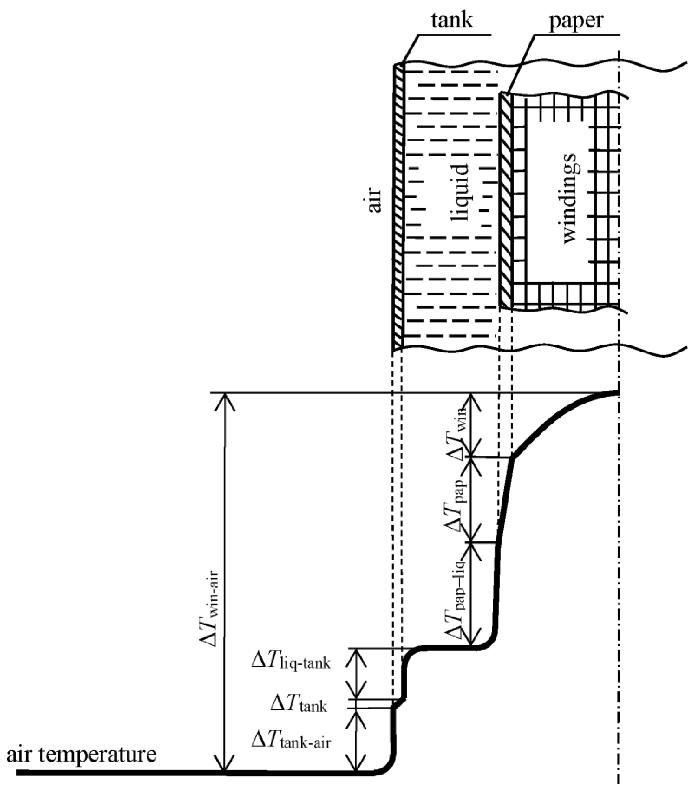
1.1. Heat Sources and Power Transformer Cooling System

One of the conditions affecting the correct operation of a power transformer is a relatively low operating temperature [1,2]. This condition is met if the heat exchange generated in the transformer is effective. Heat is generated mainly in the windings (active losses or losses in copper), the core (no-load losses or losses in iron), and the insulating elements of the transformer (mainly polarization losses) [3,4].
Heat exchange to the environment takes place on the road: heat source (windings, core) → paper insulation → electrical insulating liquid (mineral oil, esters) → tank (radiators, fans) → air, as shown in detail in Figure 1. As you can see, the temperature is distributed over many elements of the power transformer, which at the same time constitute its cooling system, namely:
  • In the windings of the transformer ΔTwin,
  • In paper insulation ΔTpap,
  • In the insulating liquid from the side of the paper insulation ΔTpap-liq and from the side of the tank ΔTliq-tank,
  • In the transformer tank ΔTtank,
  • In the air from the side of the tank ΔTtank-air.
As you can see, temperature drops occur in solid materials such as copper, iron, and paper, and in fluids such as electrical insulating liquid and air.
The temperature drops in transformer windings, paper insulation, and the transformer tank also correspond to temperature drops in solid materials. The values of these drops are determined by the heat source and thermal conductivity of the material. For windings and the transformer tank, the thermal conductivity is very large, which is a feature of metals (copper, steel). The consequence of this is a relatively small temperature drop in these elements. In turn, paper insulation is characterized by low thermal conductivity, so the temperature drops in this element would be relatively large.
The temperature drops in the electrically insulating liquid (liquid) and in the air from the side of the tank (gas) are drops in fluids. Their values are determined by the heat source and the heat transfer coefficient, which depends on many factors, including thermal conductivity, which is described in detail in Section 1.3.
The incorrect operation of the transformer cooling system may lead to an increase in the operating temperature. The negative impact of high temperature is noticeable primarily in the transformer’s insulation system (paper insulation, electrical insulating liquid). The main negative effects of high temperature include [5,6]:
  • The acceleration of aging processes of the insulation system [7],
  • A decrease in the degree of polymerization of the paper,
  • A deterioration in the dielectric properties of the paper, and electrical insulation liquid [8],
  • An increase in gas release,
  • The acceleration and formation of copper sulphides.
The acceleration of aging processes in the insulation system is described, among others, by Montsinger’s law of 8 degrees, which says that an increase in temperature by such a value result in a twofold reduction in the lifetime of the insulation system. In turn, a decrease in the degree of polymerization in the paper causes a decrease in its mechanical strength and, additionally, the release of water. Water, together with high temperature, causes a decrease in the electrical strength of the insulation system, a decrease in its electrical resistance, an increase in the dielectric loss coefficient tan(delta), and an increase in the probability of partial discharges [9,10,11,12]. An increase in the release of gas resulting from high temperatures can cause a dangerous increase in pressure in the transformer tank. An increase in temperature can also cause the ignition of electrically insulating liquids, especially mineral oil.
As you can see, one of the components of the cooling system is an electrically insulating liquid. The temperature decrease in a liquid is described in the following Formula [13]:
Δ T liquid = Δ T pap liq + Δ T liq tank = q α liquid
where ΔTliquid is the temperature decrease in the electrically insulating liquid [K], q is the surface heat load at the interface of the heat source (windings, core), and the electrically insulating liquid [W·m−2], αliquid is the heat transfer coefficient of the electrically insulating liquid at the surface of the paper insulation [W·m−2·K−1]. The smaller the temperature drop in the liquid, the more effectively the liquid gives off heat to the environment. Based on Formula (1), it can be concluded that the liquid effectively cools the transformer if the α factor has a high value.

1.2. Determination of the Temperature Field Distribution in the Power Transformer

An indispensable element of the power transformer design is a detailed analysis of the temperature field distribution [1,14,15,16,17,18]. Such a field can be obtained in two ways.
The first way is to simply calculate temperature decreases on individual elements of the transformer. In such a situation, it is assumed that the thermal properties of the materials from which the transformer is built are constant. The thermal property in the case of an electrically insulating liquid is its heat transfer coefficient α. It can be assumed that the value of this coefficient is always equal to 100 W·m−2·K−1. This approach can result in the improper design of the transformer. If the actual value of α is less than 100 W·m−2·K−1, then the temperature in the transformer will be higher than intended, which causes the faster aging of the insulation system [14,15,16]. If, on the other hand, the actual value of this coefficient is higher than assumed, then the temperature in the transformer will be lower than designed, which makes the transformer unnecessarily oversized or underloaded.
The second way to obtain the temperature field distribution of a power transformer is the use of three-dimensional computer simulations [1,17,18]. However, the process of creating a new transformer in 3D modelling programs is time-consuming and takes several weeks. While the implementation of the 3D model into programs is not laborious, the task of appropriate boundary conditions, material properties, and calculations is very time-consuming. In addition, the designer must have the appropriate qualifications and know the operation of the programs very well. In addition, these programs require fast and capacious calculating machines, which are associated with financial costs. From the information obtained from transformer manufacturers, it appears that there is sometimes a need to design a transformer faster in terms of temperature distribution.
For the above reasons, the authors propose to enrich the first method with the actual thermal values of the transformer elements that are responsible for heat transfer. In the case of an insulating liquid, such a property is the heat transfer coefficient α. The proposed method will, therefore, be free from the disadvantages of the first method, as it will be based on the correct values of the α coefficient, and free from the disadvantages of the second method because the design process will not be so time-consuming and expensive.

1.3. Determination of the Heat Transfer Coefficient α
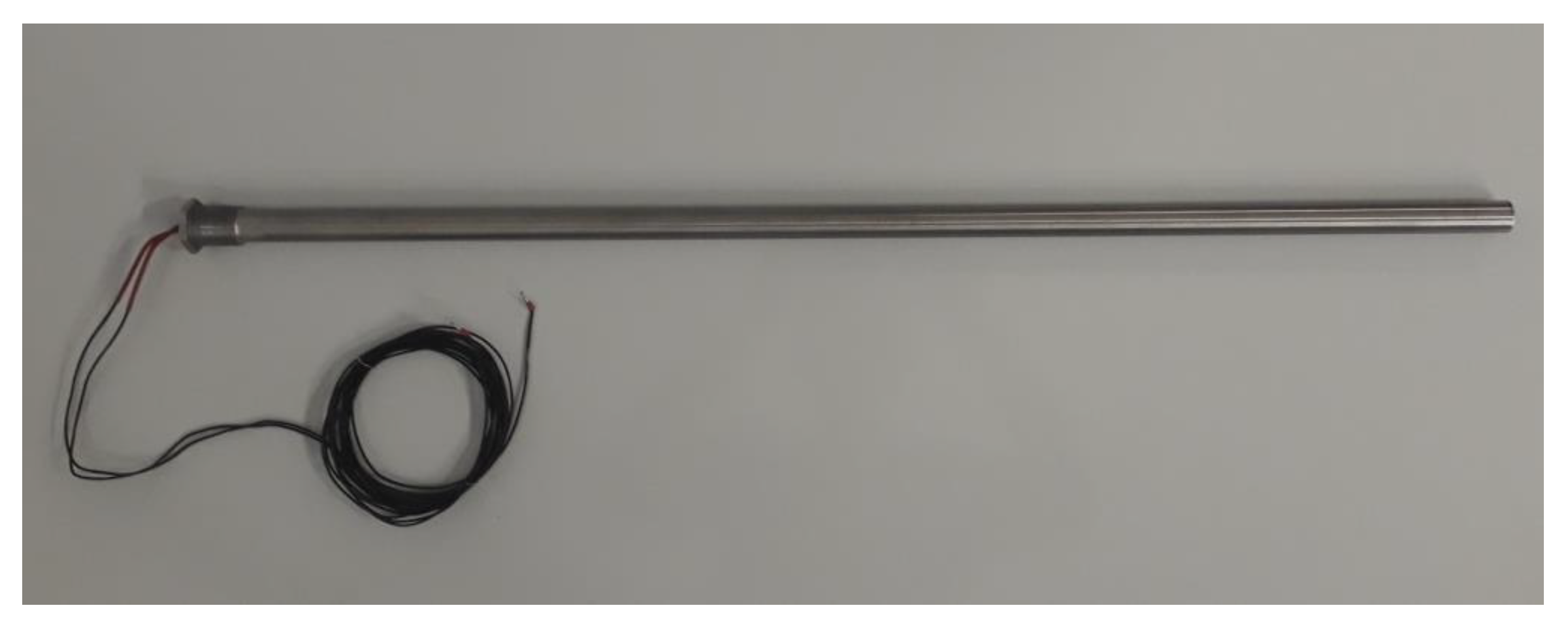
In order to determine the relationship describing the value of the α coefficient, criteria numbers, also called similarity numbers, can be used. For free or forced convection, the Nusselt Nu, Grashof Gr, and Prandtl numbers Pr are used [13,19]. The Nusselt number is the criterion for heat transfer in direct contact with heat-exchanging bodies:
Nu = α δ λ
where δ is the characteristic dimension [m] and λ represents thermal conductivity [W·m−1·K−1]. The Grashof number determines the ratio of buoyancy forces to the friction forces of the internal fluid [13]:
Gr = δ 3 g β Δ T ν 2
where g represents gravitational acceleration [m·s−2], β is the coefficient of thermal expansion [K−1], ΔT is the temperature difference between the source and the liquid [K], and ν is kinematic viscosity [m2·s−1]. In contrast, the Prandtl number is a similarity number that defines the phenomenon of heat transfer in liquids by convection [13]:
Pr = ρ ν c p λ
where ρ is density [kg·m−3] and cp represents specific heat [J·kg·K−1]. Based on the Formulas (2)–(4) you can write a relationship [13]:
Nu = c Gr Pr n
where c and n are the geometric constants. The constants c and n depend on the product of Grashof and Prandtl numbers (Table 1).
When inserting Formula (5) into Formulas (2)–(4), we can obtain a relation describing the value of the heat transfer coefficient α for convection:
α = c · λ 1 n · g n · δ 3 n 1 · β n · Δ T n · ρ n · c p n · ν n

2. Test Object

The subject of the research was various types of electrical insulating liquids used as an insulating medium in a power transformer. These liquids included mineral oil, natural ester with reduced viscosity, natural ester, and synthetic ester [21,22,23,24].
Table 2 shows the basic thermal properties of the analysed liquids. These properties include thermal conductivity λ, specific heat cp, viscosity ν, density ρ, and the coefficient of thermal expansion β [25,26,27]. These properties are shown for a relatively wide temperature range from 25 to 80 °C. All these properties have an impact on the heat transfer coefficient α, as shown in Formula (6). The data in the table are the result of previous work by the authors [26]. The intention of the authors was not to promote or act to the detriment of manufacturers of electrical insulating liquids; therefore, the article does not give the market names of the analysed liquids.

3. Motivation, Thesis and Scope of Research
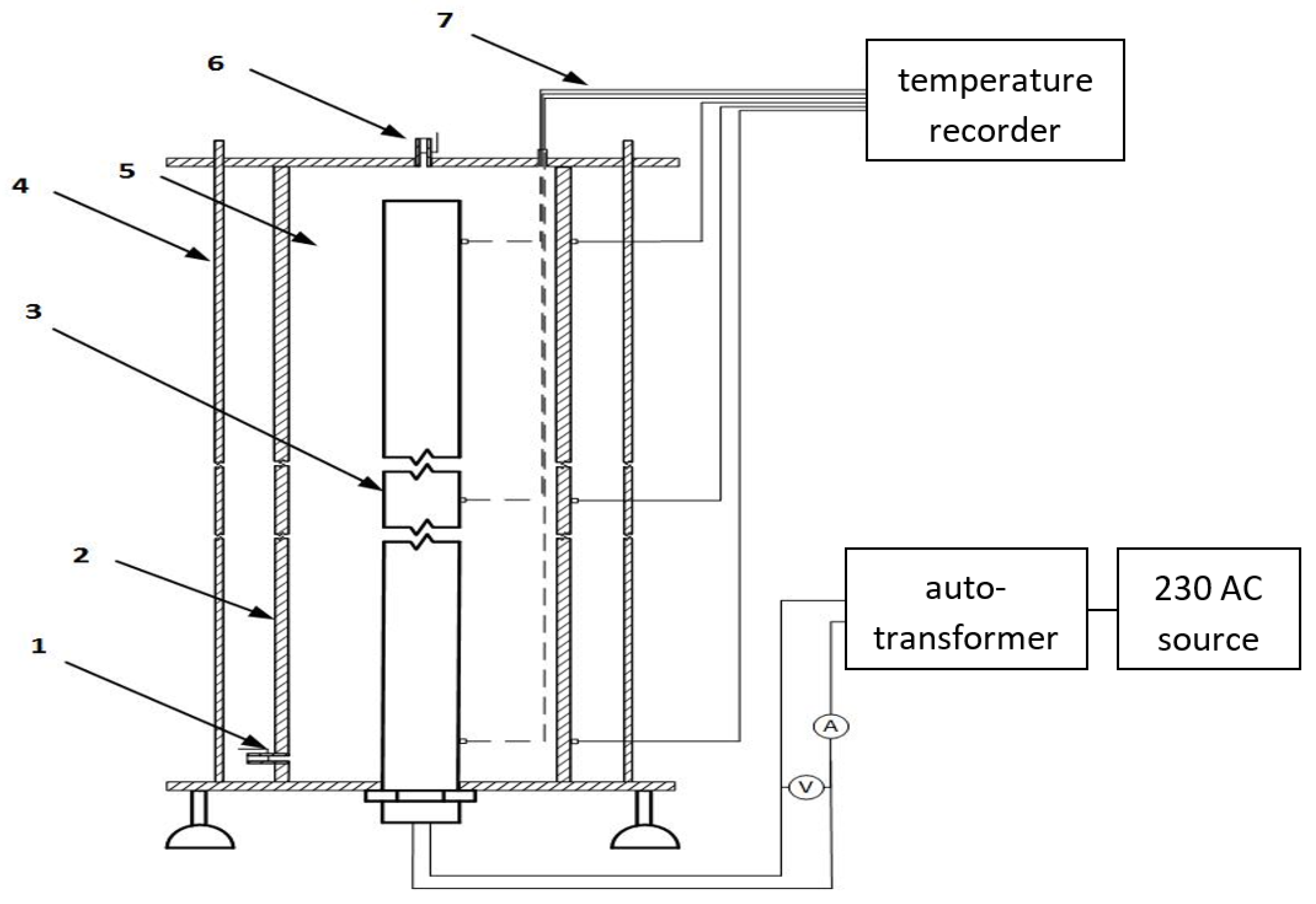
As can be seen from Formula (6), the heat transfer coefficient α depends, among other things, on the thermal properties of the liquid (λ, β, ρ, cp, ν) and the characteristic dimension of the δ which should be understood as the length of the heating element.
Based on Formula (6), it can be said that a liquid with a higher thermal conductivity λ, a higher coefficient of thermal expansion β, a higher density ρ, higher specific heat cp, and a lower viscosity ν, should have a high heat transfer coefficient α. As shown in Table 2, the thermal properties of the analysed liquids differ. This applies primarily to viscosity and, to a lesser extent, thermal conductivity. This means that the α factor probably depends on the type of electrical insulating liquid.
As mentioned in the previous paragraph, an increase in thermal conductivity λ, the coefficient of thermal expansion β, density ρ, and heat cp, and a decrease in viscosity ν, should result in an increase in the heat transfer coefficient α. Based on Table 2, it can be said that the increase in temperature, resulting from the increase in the heat load q, causes changes to the thermal properties of the analysed liquids. An increase in temperature causes a decrease in thermal conductivity, density and, above all, viscosity and an increase in specific heat and the coefficient of thermal expansion. This means that the α factor may depend on the heat load q of the surface that requires cooling.
Based on Formula (6), it can be said that the heat transfer coefficient α depends, among other things, on the length of the heating element δ in the 3n − 1 power, where n depends on the type of movement of the liquid (laminar, turbulent, Table 1). In the case of laminar motion, it is assumed, according to the literature, that n = 0.125. Then, the power value of the length of the heating element is equal to −0.625. That is, for the laminar motion, the length of the heating element affects the α coefficient in an inversely proportionate manner. However, for turbulent movement, according to data in the literature, it is assumed that the value of n is equal to 0.333. In this case, the expression 3n − 1 is zero, and the the length of the heating element should not affect the α factor.
The authors put forward the thesis that the heat transfer coefficient α depends on the type of electrically insulating liquid and the thermal load q of the cooled surface. The authors assumed that heat transfer in the electrically insulating liquid took place by turbulent movement, which meant that the length of the heating element would not affect the value of the α coefficient.
The article presents the results of research on the heat transfer coefficient α depending on the type of liquid, the length of the heating element δ, and the thermal load of the cooled surface q. The analysed liquids were mineral oil, synthetic ester, natural ester, and natural ester with reduced viscosity. The length of the heating element δ was equal to 0.8 and 1.6 m, which corresponds to the length of the transformer windings. The article analyses the effect of the heat load q with values of 1000, 2000, and 3000 W∙m−2, which corresponds to the surface thermal load that occurred in the transformer.

4. Measuring System

The general principle for measuring the heat transfer coefficient α is to heat the material and observe temperature changes. The heating of the tested element is usually carried out by means of electricity. Thanks to this, a state of thermal equilibrium can be achieved, which is manifested by a constant temperature value as a function of time. It is assumed that the entire heating power (defined by Newton’s law—formula) that will be generated as a result of the thermal disturbance caused by the flowing current will be transferred to the liquid surrounding the test element [28]:
Q = α S Δ T = α S T hot T cool
where Q is the heating power [W], S is the surface of the tested element [m2], Thot refers to the temperature on the surface of the heating element [K], and Tcool is the temperature on the surface of the tank [K].
By transforming the relationship (7) and substituting the voltage U and current I in the place of Q, the heat transfer coefficient α could be determined as:
α = Q S T hot T cool = U · I S T hot T cool
In order to determine the heat transfer coefficient α, the measuring system had to consist of a heating element introducing a thermal disturbance. This task was carried out by a heater powered by 230 V. The system also consisted of a sealed tank (metal pipe). In order to measure the thermal disturbance, measuring probes connected to the temperature recorder was mounted on the surface of the heating element and the outer surface of the tank, as illustrated in Figure 2.
A diagram of the laboratory system is shown in Figure 2. Inside the steel pipe (number 2 in Figure 2), which served as a tank, a heating element was placed (number 3—patron heater). The used tank had an external diameter of 88.9 mm, a wall thickness of 3.2 mm, and a height of 1700 mm. Patron heaters were used in the research because they have a structure that provides a large number of heat emissions from a small area. They also ensured an even temperature distribution on the surface thanks to the appropriate distribution of the heating power density. The maximum power of the heaters reached up to 25 W∙m−2. Patron heaters are characterized by high power thanks to crimping technology, which causes a high concentration of magnesium oxide and significantly improves the parameters of the heater. The raw materials that were used for the production of coil heaters are magnesium oxide of high purity, nickel-chromium resistance wires, wires in the temperature class of 260 °C or 350 °C, and stainless-steel pipes and rods. A heater with a length of 1.6 m and 0.8 m was used. Such lengths were chosen because the winding height of the designed transformers was within this range. After determining the height, the remaining dimensions had to be selected so that the heater had the ability to safely set the heat load of the cooled surface q. These requirements were met by heaters, for which the diameter was 22 mm, and the resistance was equal to around 36 Ω. Figure 3 shows one of the patron heaters that was used in the research.
The free space between the heater and the tank was filled with the tested electrically insulating liquid. As written earlier, the following new electrically insulating liquids were used in this research: mineral oil, natural ester, synthetic ester, and natural ester with reduced viscosity.
In order to protect the system against the leakage of liquid, which is associated with an increase in its thermal expansion β, and occurs with increasing temperature, and against excessive pressure increase inside the tank, valve No. 6 was used, which was open during the tests. This valve also had another function. At the time of changing the tested electrical insulating liquid to another, and after cleaning the system, it was used to pour the next tested liquid. Valve number 1 was used to pour out the tested liquid.
Thanks to the use of an autotransformer, it was possible to set the voltage U and current I, and thus, the appropriate heat output Q. This power produced a heat flux introducing a thermal disturbance. It caused a natural convective movement of the electrically insulating liquid. Thanks to this, a decrease in temperature was generated in the path of the heater and the outer surface of the tank ΔT. Despite determining the heat transfer coefficient α for the electrically insulating liquid, it was decided that the temperature on the outer surface of the tank should be read. This solution was supported by the fact that it was not possible to place the temperature sensor in the right place on the inner surface of the tank. The temperature decreases in the wall of the tank was small due to the rather high thermal conductivity of steel. Therefore, there was no fear that the choice of such a solution would have any significant impact on the final value of the heat transfer coefficient α. The final measurement of the heater power Q and the temperature decrease ΔT was made in the steady state, i.e., when the temperature stabilized. Such a condition was observed after about 4 h. In order to eliminate any measurement errors, the tests were extended to 6 h and repeated ten times for each case considered.
Pt-1000 sensors were used to measure the temperature (Figure 4). The method of their installation on the surface of the heater and the outer surface of the tank is shown in Figure 2. The principle of operation for the used sensor is based on the change in the electrical resistance of the sensor and results from the change in temperature. The number 1000 indicates the electrical resistance of the sensor expressed in Ω. The higher the resistance value, the greater its accuracy, which results from the low sensitivity of the sensor indications to the resistance of the wires connecting the sensor to the measuring system. The used sensor is intended in particular for applications in which the sensor is mounted on a surface; for example, a flat surface or other structural elements. The measuring range of the sensors ranged from −50 to 200 °C. Each of the used resistance sensors had accuracy class A and a two-wire measuring circuit. A total of six sensors were used in the research. Three measuring probes were installed on the surface of the heater on its upper, middle, and lower parts. The remaining three were mounted on the outer surface of the tank and also on its upper, middle, and lower parts.
The APEK 154 Al recorder was used to measure and record the temperature (Figure 5). Thanks to equipping the recorder with a USB port and providing the manufacturer with software for reading and recording the temperature, it was possible to connect it to a computer.
Finally, knowing the heat output of the heater Q (current I and voltage U), the area of the side surface of the heating element S, the temperature drop ΔT in the path of the heater, and the outer surface of the tank, it was possible to use the relationship (8) to determine the heat transfer coefficient α of the tested electrically insulating liquid.

5. Measurement Results

5.1. Results of Measurements of the Heat Transfer Coefficient α

This section presents the results of measuring the heat transfer coefficient α, as determined by Formula (8). Table 3 presents the values of the α coefficient depending on:
  • The type of electrical insulating liquid,
  • The heat load q of the surface to be cooled on the heating element,
  • The length of the heating element δ.
In the following sections, the results of the measurements for the heat transfer coefficient α depending on the cases presented above are discussed and commented on in detail.

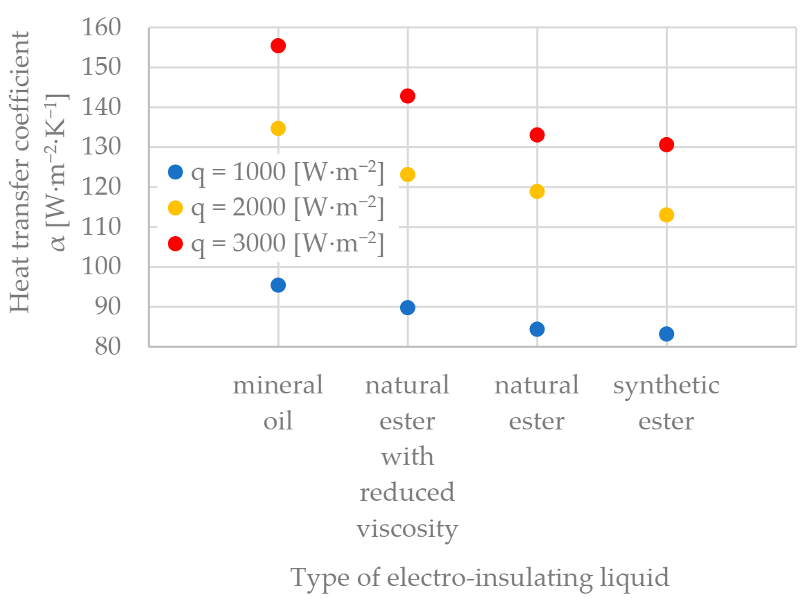
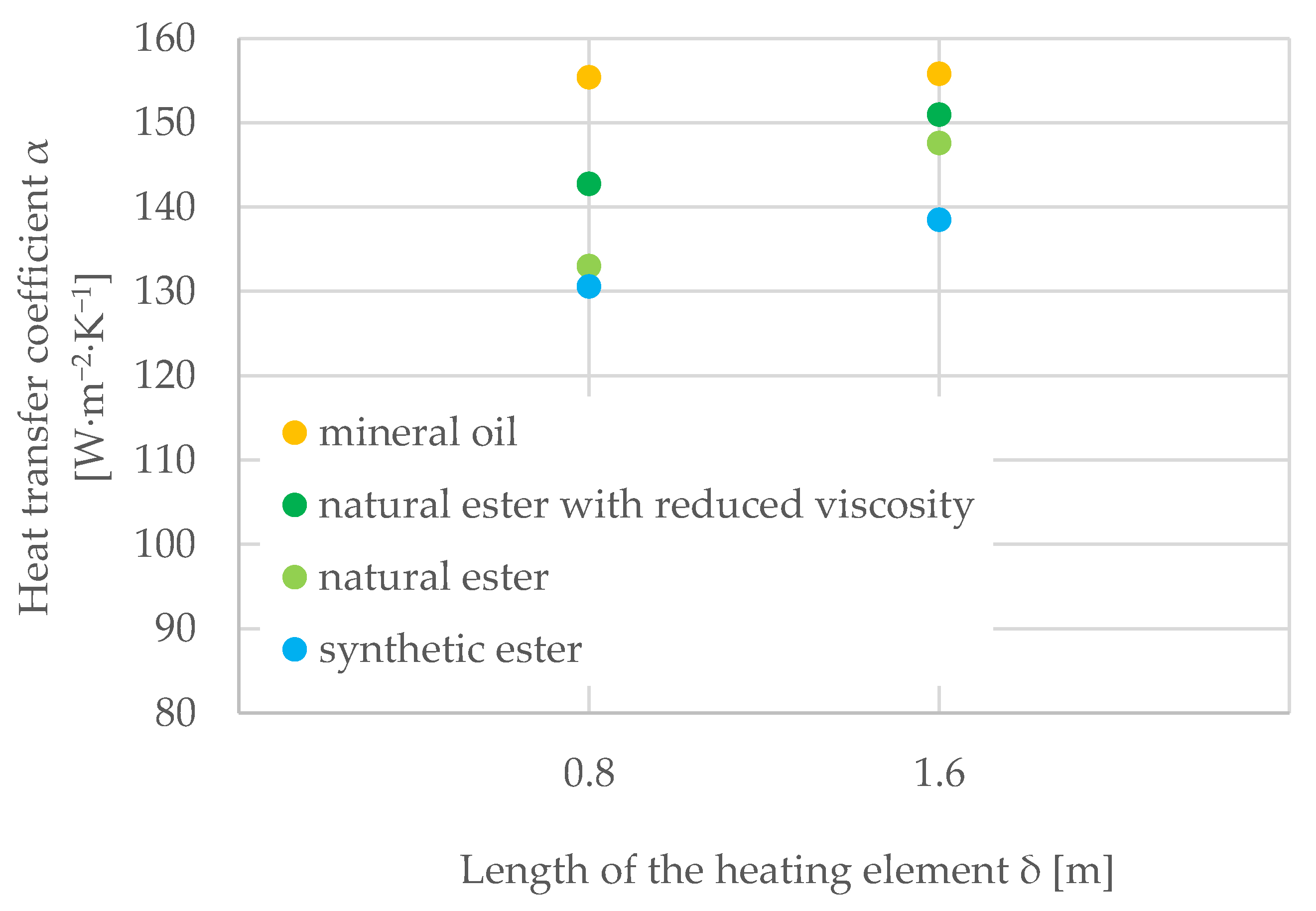
5.2. Heat Transfer Coefficient α Depending on the Type of Electrical Insulating Liquid

Figure 6 shows the dependence of the heat transfer coefficient α on the type of electrical insulation liquid for different values of the heat load on the cooled surface q. The length of the heating element was equal to δ = 0.8 m. As you can see, regardless of the value of the heat load q, the highest value of the α coefficient was for mineral oil, then for natural ester with reduced viscosity, and finally, for natural ester. The smallest value of the heat transfer coefficient occurred for the synthetic ester. Based on this, it can be concluded that the most effective liquid, from the point of view of the cooling of the transformer, was mineral oil. The least beneficial liquid was synthetic ester. The difference between the most favourable and the least favourable case was approximately 20–30%, depending on the heat load q. The differences in the α coefficient for individual liquids increased as the heat load increased. It is also worth noting that lowering the viscosity of natural ester resulted in an increase in the ester α coefficient by several percent.
In Figure 7, similarly to Figure 6, the dependence of the heat transfer coefficient α on the type of electrical insulating liquid is shown; this time for different values of the length of the heating element δ. The heat load of the cooled surface q was 3000 W∙m−2. As you can see, regardless of the length of the δ heating element, mineral oil was characterized by the highest value of the α coefficient, followed by natural ester with reduced viscosity, followed by natural ester and synthetic ester. On this basis, it can be concluded that the most effective liquid turned out to be mineral oil, and the least beneficial was the synthetic ester.
In conclusion, it can be said that mineral oil is the most effective liquid from the point of view of transformer cooling, regardless of the heat load and the length of the heating element. Esters, both natural and synthetic, are characterized by a lower value of the heat transfer coefficient α. Lowering the viscosity of the natural ester resulted in an improvement in its cooling properties, but the reduced viscosity ester still had a lower α coefficient when compared to mineral oil.

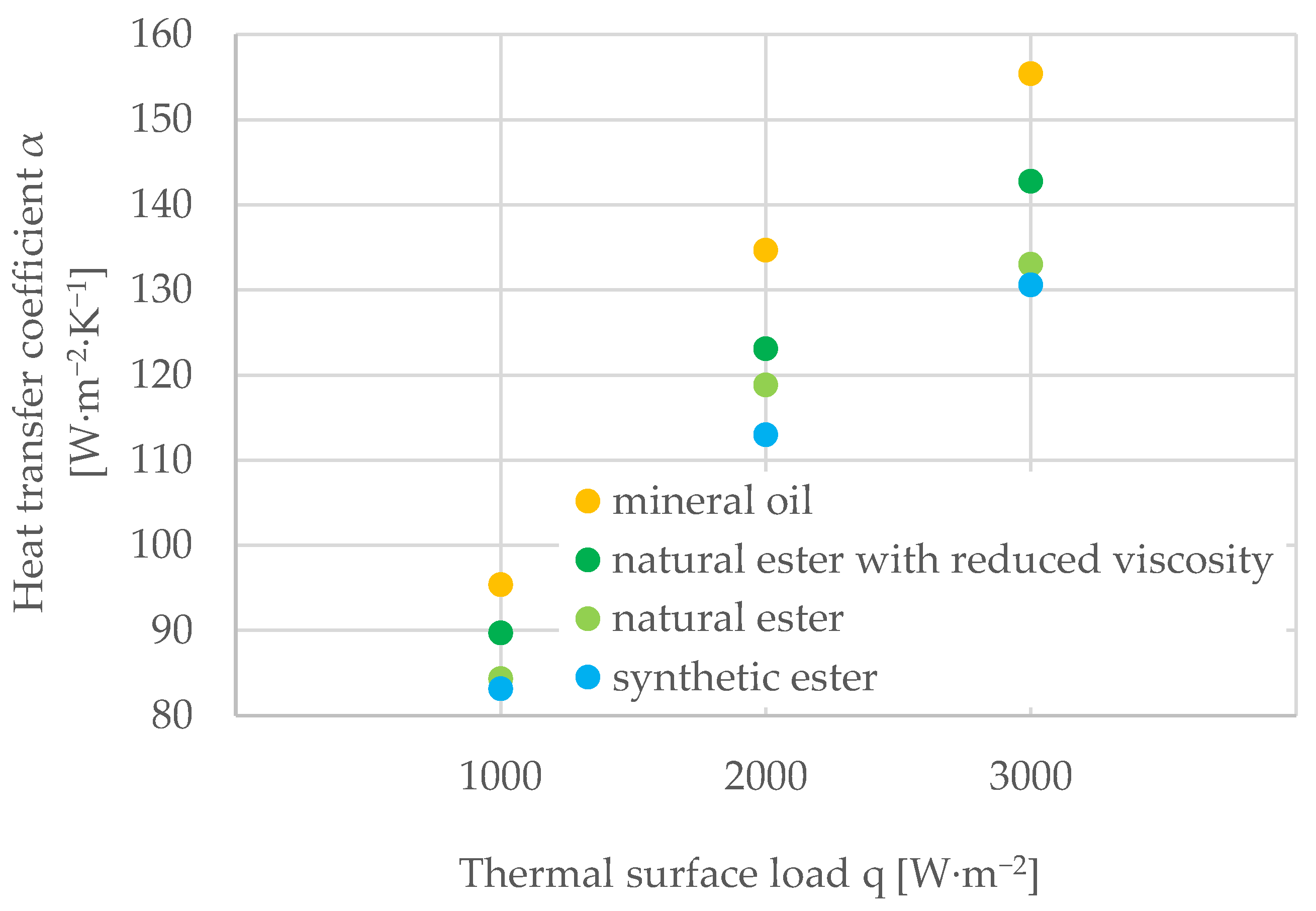
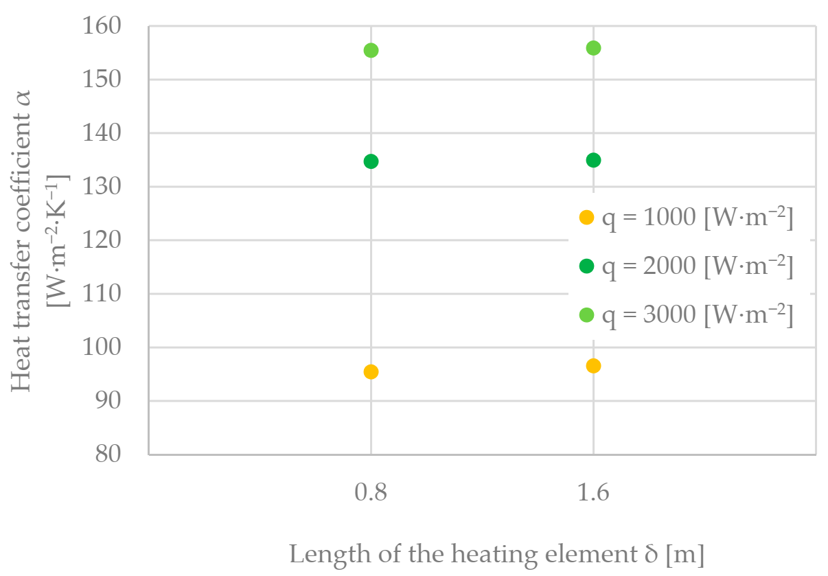
5.3. Heat Transfer Coefficient α Depending on the Value of the Heat Load q

Figure 8 shows the values of the α coefficient depending on the surface heat load of the cooled surface q for different types of electrically insulating liquid. The length of the heating element was δ equal to 0.8 m. As you can see, the values of the heat transfer coefficient increased with the increasing load q. An increase in the heat load from 1000 to 3000 W∙m−2 resulted in an increase in the α coefficient by about 50% for all the analysed liquids.
Figure 9, as in Figure 8, shows the values of the α coefficient depending on the surface heat load of the cooled surface q and for different values of the length of the heating element δ. The analysed liquid was mineral oil. As you can see, the values of the heat transfer coefficient increased as the load increased q, regardless of the length of the heating element.
An increase in the heat load on the cooling surface q caused an increase in the heat transfer coefficient α. This happened regardless of the type of electrical insulating liquid and the length of the heating element. The increase in heat load caused the α coefficient to increase by more than 50%.

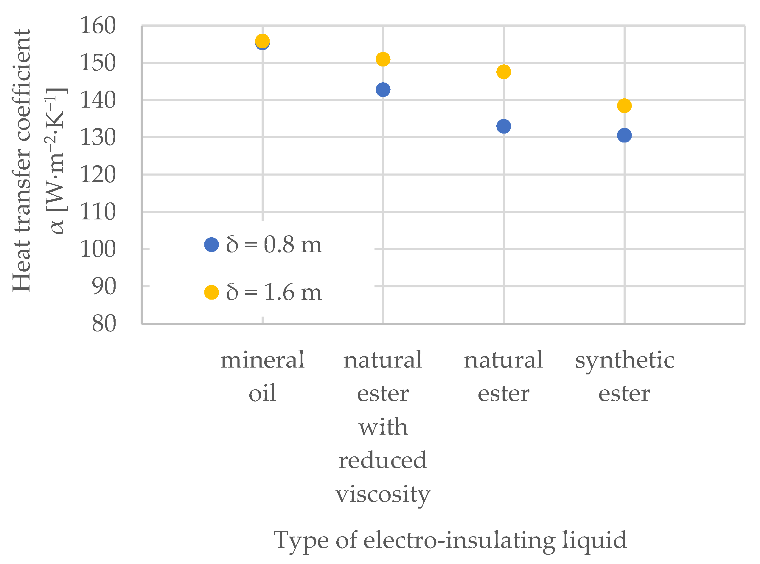
5.4. Heat Transfer Coefficient α Depending on the Length of the Heating Element δ

Figure 10 shows the α factor depending on the length of the heating element δ for different types of electrically insulating liquids. The heat load q was 3000 W∙m−2. As you can see in the figure, the increase in the length of the heating element caused an imperceptible increase in the α coefficient though this was not the case for all electrical insulation liquids. It can be concluded that, from a practical point of view, the length of the heating element had practically no effect on the value of the heat transfer coefficient.
Figure 11, as in Figure 10, shows the α coefficient depending on the length of the heating element δ, this time for different values of the heat load q. The analysed liquid was mineral oil. The increase in the length of the heating element did not cause any change in the α coefficient, regardless of the value of the heat load q.
Summing up, it can be said that the increase in the length of the δ heating element did not cause any changes in the heat transfer coefficient α. The absence of these changes was recorded regardless of the type of liquid and the value of heat load q.

6. Discussion

Mineral oil turned out to be the liquid whose heat transfer coefficient α was the highest. This meant that, compared to the other analysed liquids, it was the most effective for cooling the transformer. On the basis of Formula (6) in Chapter 3, it was found that a liquid with a higher thermal conductivity λ, a higher coefficient of thermal expansion β, a higher density ρ, higher specific heat cp, and a lower viscosity ν, should have a high heat transfer coefficient α. Meanwhile, it turned out that the thermal conductivity of the oil, its coefficient of thermal expansion, oil density, and the specific heat of oil were lower than in the case of the analysed esters (Table 2). This suggests that the factor α of oil should also be lower than the esters. However, the viscosity of the oil is lower than the viscosity of the esters, and it is this that determined that the α factor of the oil was greater than the esters. The reason for this was the fact that the viscosity of the oil was several times less than the viscosity of the esters.
The increase in the heat load of the cooling surface q, and thus the increase in temperature, resulted in an increase in the heat transfer coefficient α for all the analysed liquids by about 50%. As mentioned in Chapter 3, an increase in thermal conductivity λ, the coefficient of thermal expansion β, density ρ, specific heat cp, and a decrease in viscosity ν, should result in an increase in the heat transfer coefficient α. Based on Table 2, it can be said that an increase in temperature causes a decrease in thermal conductivity and a decrease in density, which should result in a decrease in the α coefficient. However, the increase in temperature also primarily causes a decrease in viscosity and an increase in the specific heat and coefficient of thermal expansion. Changes in the latter three thermal properties played a significant role, resulting in an increase in the α coefficient.
The length of the heating element δ did not affect the value of the heat transfer coefficient α. Chapter 3 states that the α factor depends on the length of the heating element in the 3n − 1 power. The value of the exponent is affected by the parameter n, which depends on the nature of the movement of the liquid. For the laminar motion, the length of the heating element affects the value of α because n = 0.125; therefore, the power of 3n − 1 takes the value −0.625. However, for turbulent motion, n is assumed to be 0.333. That is, the expression 3n − 1 equals 0. Thus, the length of the heating element does not affect the value of the α factor. Based on the results of the α coefficient, which were obtained depending on the length of the heating element, it can be said that turbulent movements occur for the cases under consideration.

7. Conclusions

Among the analysed electro-insulating liquids, mineral oil was characterized by the highest heat transfer coefficient α. This meant that this liquid cooled the power transformer most effectively. The key property turned out to be the viscosity, which in the case of mineral oil, is several times lower than the viscosity of esters.
The heat load on the cooling surface q influenced the value of the heat transfer coefficient α. The increase in the load, and thus the increase in temperature, caused an increase in the α coefficient of the analysed liquids. This increase should be associated primarily with a decrease in viscosity and, to a lesser extent, with an increase in specific heat and the thermal expansion coefficient of electrical insulation liquids.
The length of the δ heating element had practically no effect on the value of the heat transfer coefficient α liquid. This was due to the fact that the heat exchange was turbulent.

Author Contributions

Conceptualization, P.G. and Z.N.; methodology, P.G.; software, P.G.; formal analysis, T.B.; investigation, P.G.; data curation, P.G.; writing—original draft preparation, Z.N.; writing—review and editing, R.N. and A.T.; supervision, Z.N. All authors have read and agreed to the published version of the manuscript.

Funding

The research was financed by the Poznan University of Technology’s financial resources for statutory activity. The number of projects: 0711/SBAD/4560.

Data Availability Statement

Not applicable.

Conflicts of Interest

The authors declare no conflict of interest.

References

  1. Liu, Y.; Li, X.; Li, H.; Wang, J.; Fan, X. Experimental and Numerical Investigation of the Internal Temperature of an Oil-Immersed Power Transformer with DOFS. Appl. Sci. 2020, 10, 5718. [Google Scholar] [CrossRef]
  2. Kunicki, M.; Borucki, S.; Cichon, A.; Frymus, J. Modeling of the Winding Hot-Spot Temperature in Power Transformers: Case Study of the Low-Loaded Fleet. Energies 2019, 12, 3561. [Google Scholar] [CrossRef] [Green Version]
  3. Wang, S.; Guo, Z.; Zhu, T.; Feng, H.; Wang, S. A New Multi-Conductor Transmission Line Model of Transformer Winding for Frequency Response Analysis Considering the Frequency-Dependent Property of the Lamination Core. Energies 2018, 11, 826. [Google Scholar] [CrossRef] [Green Version]
  4. Paul, A. Practical Study of Mixed-Core High Frequency Power Transformer. Magnetism 2022, 2, 306–327. [Google Scholar] [CrossRef]
  5. Cheng, L.; Yu, T.; Wang, G.; Yang, B.; Zhou, L. Hot Spot Temperature and Grey Target Theory-Based Dynamic Modelling for Reliability Assessment of Transformer Oil-Paper Insulation Systems: A Practical Case Study. Energies 2018, 11, 249. [Google Scholar] [CrossRef] [Green Version]
  6. Zhang, X.; Ren, L.; Yu, H.; Xu, Y.; Lei, Q.; Li, X.; Han, B. Dual-Temperature Evaluation of a High-Temperature Insulation System for Liquid-Immersed Transformer. Energies 2018, 11, 1957. [Google Scholar] [CrossRef] [Green Version]
  7. Souček, J.; Trnka, P.; Hornak, J. Proposal of Physical-Statistical Model of Thermal Aging Respecting Threshold Value. Energies 2017, 10, 1120. [Google Scholar] [CrossRef] [Green Version]
  8. Wang, Y.; Gong, S.; Grzybowski, S. Reliability Evaluation Method for Oil-Paper Insulation in Power Transformers. Energies 2011, 4, 1362–1375. [Google Scholar] [CrossRef]
  9. Manea, A.; Gorjanu, T.; Lazeanu, A.; Dumitran, L.M. Effect of Electrical Accelerated Aging on DC Resistivity of Mineral Oil Used in Power Transformers. Energies 2023, 16, 294. [Google Scholar] [CrossRef]
  10. Arsad, S.; Ker, P.; Jamaludin, Z.; Choong, P.; Lee, H.; Thiviyanathan, V.A.; Ghazali, Y. Water Content in Transformer Insulation System: A Review on the Detection and Quantification Methods. Energies 2023, 16, 1920. [Google Scholar] [CrossRef]
  11. Sikorski, W.; Walczak, K.; Przybylek, P. Moisture Migration in an Oil-Paper Insulation System in Relation to Online Partial Discharge Monitoring of Power Transformers. Energies 2016, 9, 1082. [Google Scholar] [CrossRef] [Green Version]
  12. Przybylek, P.; Moranda, H.; Moscicka-Grzesiak, H.; Szczesniak, D. Application of Synthetic Ester for Drying Distribution Transformer Insulation—The Influence of Cellulose Thickness on Drying Efficiency. Energies 2019, 12, 3874. [Google Scholar] [CrossRef] [Green Version]
  13. Nadolny, Z. Determination of Dielectric Losses in a Power Transformer. Energies 2022, 15, 993. [Google Scholar] [CrossRef]
  14. Fernandez, I. The Need for Experimental and Numerical Analyses of Thermal Ageing in Power Transformers. Energies 2022, 15, 6393. [Google Scholar] [CrossRef]
  15. Fofana, I.; Hadjadj, Y. Electrical-Based Diagnostic Techniques for Assessing Insulation Condition in Aged Transformers. Energies 2016, 9, 679. [Google Scholar] [CrossRef]
  16. N’cho, J.S.; Fofana, I.; Hadjadj, Y.; Beroual, A. Review of Physicochemical-Based Diagnostic Techniques for Assessing Insulation Condition in Aged Transformers. Energies 2016, 9, 367. [Google Scholar] [CrossRef]
  17. Wang, Z.; Xu, K.; Du, Y. Temperature Rise Calculation of Magnetic Core Considering the Temperature Effect of Magnetic Properties in an Electrical Steel Sheet. Symmetry 2022, 14, 2315. [Google Scholar] [CrossRef]
  18. Gonçalves Mafra, R.; Magalhães, E.; De Campos Salles Anselmo, B.; Belchior, F.; Metrevelle Marcondes Lima e Silva, S. Winding Hottest-Spot Temperature Analysis in Dry-Type Transformer Using Numerical Simulation. Energies 2019, 12, 68. [Google Scholar] [CrossRef] [Green Version]
  19. Shen, Z.; Xu, B.; Liu, C.; Hu, C.; Liu, B.; Xu, Z.; Jin, L.; Chen, W. The Modeling and Simplification of a Thermal Model of a Planar Transformer Based on Internal Power Loss. Sustainability 2022, 14, 11915. [Google Scholar] [CrossRef]
  20. Bilal Riaz, M.; Rehman, A.U.; Awrejcewicz, J.; Akgül, A. Power Law Kernel Analysis of MHD Maxwell Fluid with Ramped Boundary Conditions: Transport Phenomena Solutions Based on Special Functions. Fractal Fract. 2021, 5, 248. [Google Scholar] [CrossRef]
  21. Zdanowski, M. Streaming Electrification of C60 Fullerene Doped Insulating Liquids for Power Transformers Applications. Energies 2022, 15, 2496. [Google Scholar] [CrossRef]
  22. Cybulski, M.; Przybylek, P. Application of Molecular Sieves for Drying Transformers Insulated with Mineral Oil, Natural Ester, or Synthetic Ester. Energies 2021, 14, 1719. [Google Scholar] [CrossRef]
  23. Wolny, S. Analysis of High-Frequency Dispersion Characteristics of Capacitance and Loss Factor of Aramid Paper Impregnated with Various Dielectric Liquids. Energies 2019, 12, 1063. [Google Scholar] [CrossRef] [Green Version]
  24. Beroual, B.; Khaled, U.; Noah, P.; Sitorus, H. Comparative Study of Breakdown Voltage of Mineral, Synthetic and Natural Oils and Based Mineral Oil Mixtures under AC and DC Voltages. Energies 2017, 10, 511. [Google Scholar] [CrossRef]
  25. Olmo, C.; Méndez, C.; Quintanilla, P.J.; Ortiz, F.; Renedo, C.J.; Ortiz, A. Mineral and Ester Nanofluids as Dielectric Cooling Liquid for Power Transformers. Nanomaterials 2022, 12, 2723. [Google Scholar] [CrossRef]
  26. Dombek, G.; Nadolny, Z.; Marcinkowska, A. Effects of Nanoparticles Materials on Heat Transfer in Electro-Insulating Liquids. Appl. Sci. 2018, 8, 2538. [Google Scholar] [CrossRef] [Green Version]
  27. Nadolny, Z.; Dombek, G. Electro-Insulating Nanofluids Based on Synthetic Ester and TiO2 or C60 Nanoparticles in Power Transformer. Energies 2018, 11, 1953. [Google Scholar] [CrossRef] [Green Version]
  28. Wisniewski, S. Heat Transfer; Scientific and Technical Publishing House: Warsaw, Poland, 2009. [Google Scholar]
Figure 1. Temperature distribution in the power transformer on all elements of the cooling system.
Energies 16 02627 g001
Figure 2. Diagram of the designed system for determining the heat transfer coefficient α; 1—valve, 2—tank (steel pipe), 3—heating element (heater), 4—pin fixing the top and bottom cover of the tank, 5—electro-insulating liquid, 6—valve, 7—measuring probes.
Energies 16 02627 g002
Figure 3. Patron heater.
Energies 16 02627 g003
Figure 4. Sensor Pt-1000.
Energies 16 02627 g004
Figure 5. Temperature recorder used in tests.
Energies 16 02627 g005
Figure 6. The heat transfer coefficient α depending on the type of electrically insulating liquid for different values of the heat load of the cooled surface q and the length of the heating element δ = 0.8 m.
Energies 16 02627 g006
Figure 7. The heat transfer coefficient α depending on the type of electrical insulation liquid, for different values of the length of the heating element δ, and the value of the heat load of the cooled surface q = 3000 W∙m−2.
Energies 16 02627 g007
Figure 8. The heat transfer coefficient α depending on the heat load of the cooled surface q for different types of electrical insulation liquid, and the length of the heating element δ = 0.8 m.
Energies 16 02627 g008
Figure 9. The heat transfer coefficient α depending on the heat load of the cooled surface q for different lengths of the heating element δ for mineral oil.
Energies 16 02627 g009
Figure 10. The heat transfer coefficient α depending on the length of the heating element δ for different types of electrical insulating liquid, and the heat load of the cooled surface q = 3000 W∙m−2.
Energies 16 02627 g010
Figure 11. The heat transfer coefficient α depending on the length of the heating element δ for different values of the heat load of the cooled surface q for mineral oil.
Energies 16 02627 g011
Table 1. Values of geometric constants c and n [20].
Nature of the FlowGr∙Prcn
no flow<10−30.450
laminar flow10−3 ÷ 5 × 1021.180.125
transitional flow5 × 10−3 ÷ 2 × 1070.540.250
turbulent flow>2 × 1070.140.333
Table 2. Thermal properties of analysed electrical insulating liquids depending on temperature [26].
25 °C40 °C60 °C80 °C
thermal conductivity λ [W·m−1·K−1]
mineral oil0.1330.1300.1280.126
synthetic ester0.1580.1560.1530.151
natural ester0.1820.1800.1780.175
specific heat cp [J·kg−1·K−1]
mineral oil1902197420772187
synthetic ester1905196420522149
natural ester2028208221662259
kinematic viscosity ν [mm2·s−1]
mineral oil17.19.65.43.4
synthetic ester55.128.314.08.1
natural ester56.332.718.311.5
density ρ [kg·m−3]
mineral oil867857845832
synthetic ester964953940926
natural ester917908892880
thermal expansion coefficient β [K−1]
mineral oil0.000750.000760.000780.00080
synthetic ester0.000760.000770.000780.00079
natural ester0.000740.000760.000780.00080
Table 3. The results of measurements of heat transfer coefficient α depending on the type of electrical insulation liquid, the heat load of the cooled surface q, and the length of the heating element δ.
Heat Transfer Coefficient α [W∙m−2∙K−1]
Mineral OilNatural Ester with Reduced ViscosityNatural EsterSynthetic Ester
length of heating element δ [m]0.8 m
q = 1000 [W∙m−2∙K−1]95.3989.7484.3483.17
q = 2000 [W∙m−2∙K−1]134.67123.12118.85112.99
q = 3000 [W∙m−2∙K−1]155.40142.79133.01130.59
length of heating element δ [m]1.6 m
q = 1000 [W∙m−2∙K−1]96.5190.7384.5086.62
q = 2000 [W∙m−2∙K−1]134.92126.04122.76121.48
q = 3000 [W∙m−2∙K−1]155.86150.99147.62138.52
Disclaimer/Publisher’s Note: The statements, opinions and data contained in all publications are solely those of the individual author(s) and contributor(s) and not of MDPI and/or the editor(s). MDPI and/or the editor(s) disclaim responsibility for any injury to people or property resulting from any ideas, methods, instructions or products referred to in the content.

