Abstract
By 2050, the European Union plans to make Europe the first carbon-neutral continent and a global leader in climate-green industries. Recently, many decisions have been taken in the world to ensure the energy transition from fossil fuel to renewable energy. The creation of renewable energy communities (REC) is among the solutions used to increase this transition. This study presents 16 different configurations for energy self-consumption in RECs containing different industrial factories. One mathematical model is proposed for each configuration, and they have been solved according to different criteria. The comparisons are made between these configurations according to economic, environmental, technical, and social criteria. Then, four multi-criteria decision-making (MCDM) methods are used to choose the best configurations considering all the criteria. For this purpose, the achieved results from the mathematical models are used as input for the MCDM methods. The findings demonstrate that the most effective configurations combine both individual and collective self-consumption. Furthermore, the inclusion of collective production results in multiple advantages, including a 64.71% rise in economic gains, a 26.95% decrease in CO2 emissions, a 21.39% improvement in self-sufficiency, and a significant increase in job creation by 175.24%. In addition, incorporating storage enables a substantial rise in the degree of self-sufficiency, leading to reduced reliance on the power grid and consequent reduction in CO2 emissions.
1. Introduction
The European Union aims to transform Europe into the world’s first carbon-neutral continent and establish its position as a top player in climate-friendly industries by 2050. At this point, several efforts have been made to meet the Paris Agreement’s goals of reducing greenhouse gas emissions and limiting global warming to 1.5 °C [1], as well as ensuring the energy transition from fossil fuels to renewable energy. Furthermore, China has proposed an ambitious plan to reach carbon neutrality by 2060, with a target of peaking carbon emissions by 2030 [2]. In this setting, renewable energy communities have emerged as local projects to accelerate the energy transition while simultaneously giving environmental, economic, technical, and social advantages to its members. [3]. There are different ways to define a renewable energy community (REC), but the most common definition involves a group of traditional energy consumers, as well as prosumers who can both produce and consume energy. These individuals or entities work together to develop and use renewable energy sources, with the goal of reducing their reliance on non-renewable energy sources. The REC may involve households, businesses, and other stakeholders who collaborate to create a more sustainable energy system that benefits the community and the environment [4].
Renewable energy community modeling is a technique used to simulate the behavior of a community that is powered by renewable energy sources. It involves using mathematical models to simulate the energy production and consumption of a community, and to optimize the energy flows between different sources and users. The first step in renewable energy community modeling is to collect data on the energy consumption and production of the community. This includes information on the types of renewable energy sources that are available, as well as the energy demand from various sources. Once these data have been collected, mathematical models can be used to simulate the energy flows within the community. Simulations can be used to evaluate the impact of renewable energy on the community’s energy consumption, cost, and carbon emissions, and to identify the most effective strategies for promoting renewable energy adoption. The results of the simulations can also be used to inform policy decisions and to communicate the benefits of renewable energy to the community. For instance, Cosic et al. [5] focused on the development of new optimization strategies for renewable energy communities that can balance energy demand and supply. They proposed a mixed-integer linear programming (MILP) model for this purpose. According to the findings, the use of the REC can result in a notable 15% decrease in overall yearly energy expenses and a 34% reduction in CO2 emissions by allowing community members to share energy resources. Overall, renewable energy community modeling is a powerful tool for designing and optimizing renewable energy systems. By simulating the behavior of a community over time, it can help to identify opportunities for energy savings and cost reductions, while also promoting the use of renewable energy sources to reduce greenhouse gas emissions and combat climate change.
Renewable energy community modeling is also a tool that allows for the exploration of various configurations for the self-consumption of renewable energy within a community. Different self-consumption configurations can be defined and tested using renewable energy community modeling to determine which one is the most efficient and effective for a particular community. For example, the model can explore the impact of different levels of renewable energy generation, storage capacity, and demand profiles on the self-consumption of renewable energy within a community. This can help to identify the most effective combination of these factors to maximize the use of renewable energy and promote benefits within the community. Many researchers around the world are focused on studying energy self-consumption within renewable energy communities. Few of these have tackled the comparison between the different configurations of energy self-consumption based on different criteria. For instance, Liu et al. [6] evaluated collective self-consumption scenarios with and without storage using economic, environmental, and technical standards for an energy community comprising residential, office, and campus buildings. The findings indicate that incorporating batteries into collective self-consumption reduces carbon emissions by 71.23% and grid penalty costs by 145.36%, while also increasing the net present value.
Rehman et al. [7] aimed to optimize the integration of renewable electricity generation systems, electric storage, grid connection, and electric vehicles within a community. They analyzed different combinations of these factors, considering technical and economic aspects, with a focus on collective self-consumption both with and without storage. The results indicate that encouraging self-consumption can lead to technical and financial improvements in the energy system, and that the integration of seasonal storage and batteries can increase self-consumption. Ceglia et al. [8] compared a renewable energy community in which each user is equipped with photovoltaic power systems with the conventional configuration in which each user draws electricity from the power grid. The users are connected by a microgrid to share the electricity produced, and they are also paralleled with the power grid. The results show that the renewable energy community avoids 39.5 t/year of CO2 emissions compared to the traditional configuration without the sharing approach. Alonso et al. [9] Compared the economic performance of energy management between the individual and collective self-consumption cases under several regulatory frameworks. The results show that the economic benefits of the creation of the energy community are greater than the benefits that most consumers can obtain individually. Vivian et al. [10] investigated whether a renewable energy community based on the sharing of electricity produced by local photovoltaic systems could help to reduce the operational costs of district heating systems with a high number of heat pumps. The results suggest that collective self-consumption within the renewable energy community is a viable option to improve the techno-economic performance of district heating networks. Pulazza et al. [11] compared five cases of configurations where each consumer can have their own PV installation and battery with the sharing of a biogas power plant between consumers. Results show that the cases with storage increase self-consumption and decrease prices. In the same context, Spertino et al. [12] compared the configurations of individual self-consumption with and without the addition of batteries and exchange between units in an energy community. Results show that self-sufficiency increases from 54% without storage to 74% with storage and can reach 100% with storage and exchange between units.
In another study, Gribiss et al. [13] presented a novel energy self-consumption strategy that combined individual and collective self-consumption with battery integration and the option of selling excess energy. This strategy was compared with the configuration of individual self-consumption, and the results show that the economic benefits obtained by working with a collective strategy are better than by working individually.
The result of this state of the art illustrates that there aren’t many works that deal with the comparison between different energy self-consumption configurations considering different criteria. This study is focused on the comparison between 16 configurations in the REC based on economic, environmental, technical, and social criteria.
Moreover, in this study, our objective is to select the best configurations for a REC that take into account these four criteria together. Multi-criteria decision-making (MCDM) methods are used in the literature to solve decision and planning problems involving multi-criteria. MCDM methods have been applied to different types of energy problems in recent years. The advantage of these methods is that they allow the evaluation of multiple criteria, even if they are contradictory. The technique is a well-known tool for solving complex real-life problems due to its intrinsic ability to judge diverse alternatives concerning various decision criteria to choose the best option [14]. Some popular MCDMs are analytic hierarchy Process (AHP), weighted sum model (WSM), weighted product model (WPM), technique for order preference by similarity to ideal solution (TOPSIS), VIKOR, PROMETHEE, and ELECTRE [15]. These methods are applied to different domains such as project selection and implementation of the installation of energy production. The selection of an optimal location for the installation of renewable energies is important, as it can reduce the cost of the project and also ensure the maximum production of electricity [16]. For example, Salameh et al. [17] selected between nine hybrid renewable energy systems to meet electricity and hydrogen demands in a city in Saudi Arabia using TOPSIS. The reliability of this method has been approved using other techniques such as evaluation based on distance from the average solution (EDAS). In another study, Haaren and Fthenakis [18] used MCDM methods for selecting a wind-farm site using spatial data and multiple criteria in New York.
To our knowledge, the literature does not contain any work that discusses the selection of the best energy self-consumption configuration according to different criteria using MCDM methods. In this study, four MCDM methods were used to select the best configurations of energy self-consumption in the REC based on four criteria and four scenarios.
The structure of this article is as follows: Section 2 provides a description of the problem and introduces the configurations of energy self-consumption. Section 3 presents the different criteria to be optimized. Section 4 and Section 5 present, respectively, the modeling of the configurations used in this study and the generation of the data. The MCDM methods employed in this research are presented in Section 6. Section 7 discusses the findings, and Section 8 presents conclusions and suggests future research directions.
2. Problem Definition
Facing the negative changes to the global climate, fossil energy sources are being gradually replaced by renewable energy sources. This led to a change in electricity consumption and distribution model. Recently, energy consumers connected to the distribution networks have played an increasingly important active role in the power system. The aggregation of these energy consumers who produce and self-consume their energy within the same geographical area expresses a new way of using renewable energy represented by REC. In this context, several configurations of energy self-consumption have been presented in the literature. The main elements of these configurations are:
- Individual self-consumption (ISC), where each consumer produces renewable energy for their own energy needs.
- Collective self-consumption (CSC), where all members of the energy community share a renewable energy production.
- Individual storage (IS), where the member of the energy community stores its surplus of energy production.
- Collective storage (CS), where all members of the energy community store their surplus of renewable energy.
- Energy sharing is also one of the most widely used options where members of the energy community can exchange locally produced energy with each other (peer-to-peer).
By considering these elements, these configurations are divided into five categories. The first category represents the case where each factory has its own renewable energy production. The second category is the case where all factories have a common renewable energy production. The third category is the combination of categories 1 and 2. The fourth category and the last category are, respectively, the same cases as the first category and the third category but with the addition of the energy exchange between the factories. For all these categories, the option of adding individual and collective storage has been studied.
In total, 16 configurations were selected. Figure 1 represents the different configurations of energy self-consumption that can be found in the REC.
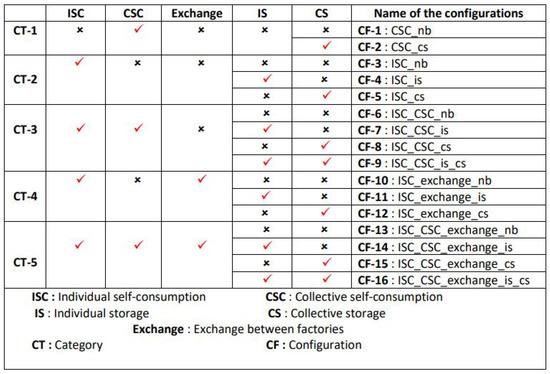
Figure 1.
Different configurations of energy self-consumption in REC.
For example, Figure 2 represents the schema of the configuration that includes individual collective self-consumption and individual collective storage (CF-9).
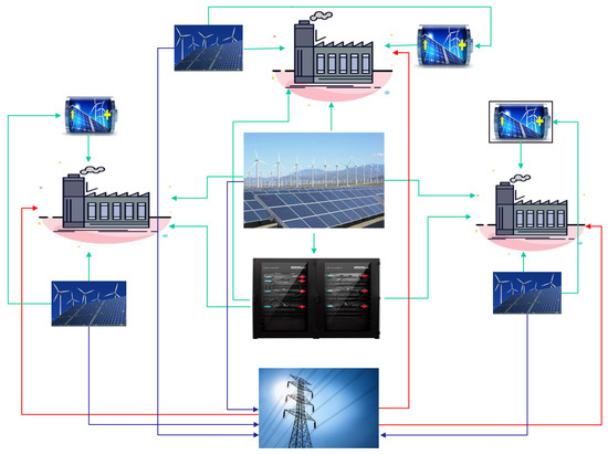
Figure 2.
Schema of configuration CF-9 for a case of three factories [19].
To find the one that gives the best results, each configuration was modeled and tested according to different criteria. The selection of the criteria to be optimized is presented in Section 3 and the modeling of these configurations is presented in Section 4.
The result of the optimization of these configurations according to the different criteria is represented as a decision matrix with m criteria and n configuration. It contains as the matrix elements, where it denotes the performance value of configuration () on criterion (). In this study, n = 16 and m = 4.
This matrix is used as input for the MCDM methods to find the configuration that gives the best results for the considered criteria. Section 5 represents the four MCDM methods used in this study.
3. Criteria Selection
This section aims to identify and classify the indicators used in this study to evaluate the economic, environmental, technical, and social criteria of energy communities.
The economic impact is the most dominant in the design of energy communities. In general, economic objectives are represented using a cost function that includes capital, operating, and maintenance costs over the life of the energy system. The economic criterion chosen in this study is the one represented in Equation (1) [20]. It allows the calculation of the net present value to analyze the profitability of an investment in a project for a given period [20]. With is the annual cash flow at year n, N is the project lifetime, r is the discount rate, and is the initial investment cost.
The environmental criterion chosen in this study measures the emission reductions. It uses the emission factor (KgCO2/KWh) for electricity from the grid (), the emission factor (KgCO2/KWh) for electricity from the photovoltaic panels (), and the emission factor ((KgCO2/KWh) for electricity from the batteries (). Equation (2) calculates the CO2 emissions.
The self-sufficiency ratio is chosen to evaluate the technical criterion. It calculates the proportion of an energy community’s demand () that is satisfied by photovoltaic production () and batteries () [21]. Equation (3) represents the calculation of the energy self-sufficiency ratio in an energy community [21].
The number of new job opportunities created by the realization of a renewable energy community was considered for the social criterion. This criterion could be a determining factor to increase the acceptance of investment in REC. According to [22], 30 new jobs can be created for each MW of photovoltaic energy installed. Equation (4) represents this criterion [22].
The aim is to minimize the environmental criterion and maximize the economic, technical, and social criteria.
4. Mathematical Model
In this section, we will present different parameters, the decision variables, and the different parts to model these configurations. To clarify this section, we will present the detail of the modeling of the configuration presented in Figure 1. In Appendix A, the different parts of the modeling of the other configurations are presented.
The notations f, p, g, dbf, cbf, dbp, and cbp in the decision variables and parameters correspond, respectively, to the factory, the shared production, the grid, discharge of the factory’s battery, charge of the factory’s battery, discharge of the shared battery, and charge of the shared battery to distinguish the source of energy production.
Sets:
: set of factories in the REC.
: set of the time period (in hours).
: set of shared photovoltaic (PV) installations.
Parameters:
: The amount of energy required by factory j during period t.
: The amount of energy produced by 1 kW of photovoltaic capacity installed the shared photovoltaic system i during period t.
: The amount of energy produced by 1 kW of photovoltaic capacity installed in factory j during period t.
and : The cost associated with the energy consumed during period t from various sources: the factory’s production, the power grid, shared production, the factory’s battery, and shared battery, respectively.
: The price earned for the energy sold to the power grid during period t.
and : The minimum level of charge in the shared battery and the battery of factory j, respectively.
and : The amount of energy lost during the battery’s charging process and the amount of energy lost when the battery discharges, respectively.
: The proportion of the costs incurred by a particular factory j towards the creation of the shared photovoltaic installations and the shared battery.
Decision variables:
and : The amount of energy obtained by factory j during period t from various sources: its own production, the power grid, shared photovoltaic system i, its own battery, and the shared battery, respectively.
and : The amount of energy that factory j and shared photovoltaic system i sold to the power grid during period t, respectively.
and : The quantity of energy stored by factory j in its battery and by the shared photovoltaic system i in the shared battery during period t, respectively.
The combined quantity of energy that is sold to the power grid during period t by all the shared photovoltaic systems.
and : The amount of photovoltaic power capacity that is installed in factory j and the shared photovoltaic system i, respectively.
and : The minimum level of charge in the battery of factory j and the shared battery, respectively.
and : The charge level of the shared battery and the battery of factory j during period t, respectively.
: A binary variable that equals 1 if the shared battery is in a state of charging during period t, and 0 otherwise.
: A binary variable that equals 1 if the shared battery is in a state of discharging during period t, and 0 otherwise.
: A binary variable that equals 1 if the battery of the factory j is in a state of charging during period t, and 0 otherwise.
: A binary variable that equals 1 if the battery of the factory j is in a state of discharging during period t, and 0 otherwise.
: The expenses related to installing photovoltaic system and a battery in the factory j for the duration of horizon H.
: The expenses associated with the factory j for installing the shared photovoltaic system and shared battery during the horizon H.
: The overall expenses associated with installing the shared photovoltaic system and shared battery during the horizon H.
The objectives to be minimized and maximized are presented in the section of criteria selection.
The constraints are divided into six blocks:
- Demand satisfaction.
- Production capacity available in the factories.
- Production capacity available in the shared photovoltaic installations.
- Amount of energy given by the shared installations to each factory.
- Storage in the batteries of the factories.
- Storage in the shared battery.
In the following, we detail the constraints of the configuration CF-9 presented in Figure 1. For the other configurations, the constraints are presented in Table A1.
4.1. Demand Satisfaction
Constraint (5) guarantees that the aggregate energy demand of every factory, denoted as j, is satisfied by the available energy sources in the collective production, the respective factory, and the power grid during time period t.
4.2. Production Capacity Available in the Factories
Constraint (6) mandates that the sum of the energy consumed by a given factory j, the energy stored in its battery, and the energy sold to the grid, must be equivalent to the total amount of energy generated by the same factory j, during time period t.
Constraint (7) guarantees that the dimensions of photovoltaic systems installed within the factories are restricted to a specific limit, denoted as .
4.3. Production Capacity Available in the Common Production Park
Constraint (8) ensures that, during period t, the total amount of energy obtained from the shared photovoltaic system denoted as i, combined with the energy stored in the shared battery from source i, and the energy sold to the power grid from the shared photovoltaic system i must be equivalent to the total amount of energy that is produced by the shared photovoltaic system i at period t.
Constraint (9) guarantees that the capacity of communal photovoltaic systems represented by i are restricted to a specific size limit, denoted as .
4.4. Amount of Energy Given by the Shared Production Park to Each Factory
Constraint (10) denotes the proportion of energy that each factory j will obtain from the collective production, and the collective battery during the time horizon H.
4.5. Storage in the Batteries of the Factories
Constraints (11)–(13) indicate, respectively, the state of charge for the battery in factory j at the beginning of the time horizon, at the end of the time horizon, and during period t [23].
Constraint (14) ensures that the battery belonging to factory j is protected from rapid deterioration. In the literature, and are considered to be parameters [23]. In this study, we consider as a decision variable to size the batteries considering a limit that cannot be exceeded (presented in constraint (15))
Constraint (15) guarantees that the battery capacity in factory j is restricted to a maximum size limit denoted as .
Additionally, the quantity of energy charged into and discharged from the batteries must adhere to the constraints of the minimum and maximum allowable limits.
Constraint (16) denotes the highest quantity () of energy that can be added to the battery in factory j during time period t, while constraint (17) specifies the highest amount () of energy that can be removed from the battery in factory j during period t.
To increase the lifetime of the batteries, in this study, we have considered that the battery cannot be charged and discharged at the same time [24]. Constraint (18) represents the selection between either charging or discharging the battery in factory j during period t.
4.6. Storage in the Shared Battery
The same constraints as the factories batteries are considered for the shared battery as follows.
Constraints (19)–(21) indicate, respectively, the state of charge for the collective battery at the beginning of the time horizon, at the end of the time horizon, and during period t.
Constraint (22) ensures that the collective battery is protected from rapid deterioration.
Constraint (23) guarantees that the capacity of the collective battery, which is denoted as , is not surpassed.
Constraint (24) denotes the highest quantity () of energy that can be added to the collective battery during time period t, while constraint (25) specifies the highest amount () of energy that can be removed from the collective battery during period t.
Constraint (26) represents the selection between either charging or discharging the shared battery during period t.
5. Data Generation
This section describes how the model data, such as photovoltaic installations production, investment costs, and energy prices, were generated. The generation of this data was completed using the work of Pedrero et al. [25] and the data from the European Commission’s Photovoltaic Geographical Information System (PVGIS) [26].
To calculate the energy produced by each solar installation at different times during a specified period, the PVGIS tool is employed. In this study, the PVGIS-SARAH radiation database was chosen because it offers photovoltaic load profiles with hourly resolution for the years 2005 to 2020. These profiles were used to create an annual average photovoltaic load profile.
The amount of energy demand for the factories is generated using the data presented in [27]. For example, the average monthly energy consumption for three factories is presented in Figure 3.
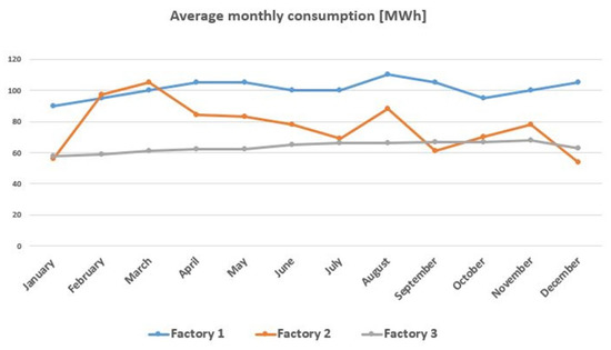
Figure 3.
An example of average monthly consumption of three factories.
The investment expenses for both the factories and the shared park are considered the same as Pedrero et al’s work [25]. This information is presented in Table 1 and Table 2.

Table 1.
Costs of PV installations.

Table 2.
Economic factors used in investment cost calculations.
The contribution cost for each factory is calculated in Table 3.

Table 3.
Contribution percentage for each factory.
Purchasing electricity from the grid is the most costly choice available, whereas buying energy from the factory is the most economical option. Table 4 represents these TOU prices.

Table 4.
TOU prices of different energy sources.
6. MCDM Methods
To compare these configurations, four MCDM methods are used: weighted sum (WS), weighted product (WP), technique for order of preference by similarity to ideal solution (TOPSIS), and evaluation based on distance from average solution (EDAS).
6.1. TOPSIS Method
In 1981, Hwang and Yoon created TOPSIS as a method for making decisions based on multiple criteria [28]. This technique is straightforward in both its design and implementation, relying on a ranking approach. The first step of this method involves identifying an ideal solution and a negative ideal solution. Then, the alternative that is closest to the ideal solution and farthest from the negative ideal solution is selected by measuring its Euclidean distance. The steps to implement this methodology are as follows:
Step 1: Develop a decision-making matrix presented in Section 2.
Step 2: Calculate the normalized matrix (this method uses quadratic normalization).
Step 3: Calculate the weighted normalized matrix.
Step 4: Calculate the ideal best and ideal worst solutions.
Step 5: Calculate Euclidean distance from the ideal best and the ideal worst.
Step 6: Calculate performance score.
Step 7: Rank the alternative.
6.2. EDAS Method
The EDAS method is also a distance-based approach that uses the positive and negative distances from the average solution to select the best alternatives. This method is summarized in the following steps:
Step 1: Develop a decision-making matrix presented in Section 2.
Step 2: Determine the average solution according to all criteria.
Step 3: Calculate the positive distance from the average solution (PDA) and negative distance from the average solution (NDA) for all criteria.
Step 4: Calculate the weighted sum of PDA () and NDA () for all alternatives.
Step 5: Calculate the normalized values of and .
Step 6: Calculate the appraisal score () for all alternatives.
Step 7: Rank the alternative.
6.3. WSM and WPM
The idea of this method is to calculate the overall performance of an alternative as a sum of the products of the normalized performance scores and the criteria weights. The best alternative is that which has the first score. The following steps summarize this method:
Step 1: Develop a decision-making matrix presented in Section 2.
Step 2: Calculate the normalized matrix (this method uses linear normalization).
Step 3: Calculate the sum of the products between the normalized performance scores and the criteria weights.
Step 4: Rank the alternative
The weighted product method (WPM) is similar to the WSM, with the main difference being that instead of addition in the main mathematical operation, there is now a multiplication.
7. Results and Discussions
This section presents the gathered results using several numerical experiments. The section is divided into two sub-sections. The first part presents and discusses the obtained results from the mathematical models. One illustrative example is used to clarify the procedure of decision variables selection in a renewable energy community. Then, the second part describes the results coming from MCDM methods.
7.1. Energy Management in a REC Configuration
In this work, each configuration was modeled mathematically and solved by CPLEX using four different objectives: economic, environmental, technical, and social. To evaluate the performance of each configuration based on each objective, several numerical instances were generated by varying the number of factories within the renewable energy community, and the amount of energy demand of each factory during each period. The optimization horizon H is considered equal to 1 year that is presented in hours (8760 h).
Please note that the results presented in matrix and Figure 4 represent the average of the obtained values from these numerical experiments over the horizon H for one factory.
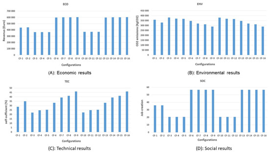
Figure 4.
Optimization results.
Figure 4 presents the obtained results for each configuration based on each criterion. Figure 4A illustrates that the configurations which integrate both individual and collective self-consumption (CF-6 to CF-9 and CF-13 to CF-16) yield the highest economic benefit. This highlights how including collective self-consumption can significantly increase the income generated by community members. To provide an illustration, if we compare the CF-4 configuration which only includes individual self-consumption, and the CF-9 configuration which combines both individual and collective self-consumption, there is a 64.71% increase in the advantages reaped by the community.
Moreover, combining individual and collective self-consumption in specific configurations has an added benefit of reducing greenhouse gases. Figure 4B indicates that these configurations have the least amount of emissions. The configurations CF-9 and CF-16 demonstrate the greatest reduction in greenhouse gas emissions by incorporating individual and collective storage. This is achieved by storing excess solar energy and using it during times of higher energy demand, instead of relying on the power grid.
Furthermore, Figure 4C demonstrates the significance of storage. Configurations that use collective and/or individual storage exhibit a greater degree of self-sufficiency when compared to other configurations. As an illustration, in categories CT-3 and CT-5 presented in Figure 1, the self-sufficiency rate of configurations that integrate a storage system increases by 12.95% in comparison to the others.
In addition, Figure 4D illustrates how the combination of individual and collective self-consumption is significant in creating new employment opportunities within an energy community.
To gain a better understanding of the energy management process in an energy community and to provide more clarity on the decision variables of the models, the optimal solution for configuration CF-9 with three factories in one day (day 158) are presented in the following.
Figure 5 illustrates the energy consumption and production of three factories, along with the collective production. In the graph, “D_f” and “Q_f” refer to the energy consumption and energy production of a factory, respectively. Each factory is also labeled with a number. For instance, “D_f1” indicates the energy consumption of factory 1, while “Q_f1” represents its energy production. Photovoltaic energy is generated in factories and the shared park between 7 a.m. and 8 p.m. due to the absence of sunlight at night.
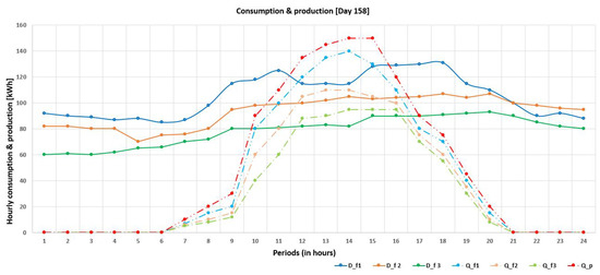
Figure 5.
An example of energy consumption and production in a REC for day 158.
The production and consumption of energy are used as input of the model. By using CPLEX and other data presented in the data-generation section, the optimal solution can be obtained. The results for our example are displayed in Figure 6, Figure 7 and Figure 8.
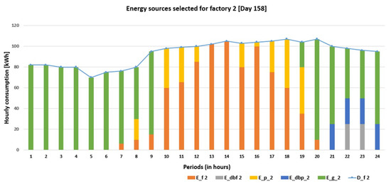
Figure 6.
The selected energy sources for factory 2 during day 158.
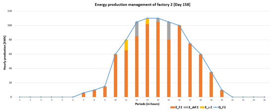
Figure 7.
Energy production management of factory 2 during day 158.
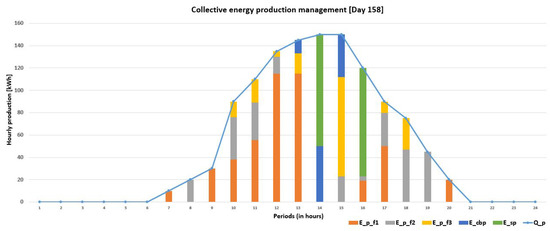
Figure 8.
Collective energy production management during day 158.
The legends presented in these three Figures are among the decision variables that were presented in Section 4. For instance, the legend “E_f 2” presented in Figure 6 is the decision variable with and .
Figure 6 shows the best energy sources used to meet the demand of the second factory in each hour of day 158.
As can be seen in Figure 6, during the initial periods, factory 2 uses the power grid’s energy as there is no photovoltaic production. Between periods 10 and 18, the factory satisfies its demand through a combination of individual production and shared production. The excess energy generated by the factory’s own photovoltaic production is stored in its individual battery, while surplus energy generated by shared photovoltaic production is stored in a collective battery (see Figure 7 and Figure 8). These stored quantities of energy are then used during the night to meet the demand between periods 21 and 24. The remaining demand in each period is fulfilled by the power grid.
Figure 7 depicts how the photovoltaic production of factory 2 is being managed.
Figure 7 reveals that most of the production from factory 2 is used to meet its own requirements, and any excess energy is either put away in its battery or sold to the power grid. The decision of whether to store or sell the energy depends on factors such as the battery’s capacity and the prevailing rates for energy storage and sales. As depicted in Figure 6, the energy that is stored in the battery during periods 12, 14, and 15 is used to fulfill the factory’s demand during periods 21 and 22.
Similarly, Figure 8 illustrates how shared photovoltaic production is handled.
7.2. Configuration Selection Using MCDM Methods
This previous part allows us to find a decision matrix that gives the value of each configuration for each criterion. The results of this part are presented in matrix . For example, the value of row i and column j in this matrix corresponds to the average value obtained by solving the model of configuration i according to criterion j for different instances.
To compare the results between the proposed configurations, the obtained decision matrix is used as input for four MCDM methods. To evaluate the results, these methods were applied with four criteria weighting scenarios to analyze the impact of each criterion on the results. The difference between these scenarios is that, in each scenario, we give priority to a particular criterion. The first scenario assigns equal significance to all four criteria. On the other hand, the second, third, and fourth scenarios assign importance to the economic, environmental, and social criteria, respectively. These scenarios are adapted from [29]. The objective is to assess how this preference impacts the comparative results. The details of these scenarios are as follows:
- Scenario 1 (S1) allocates weights of 0.25, 0.25, 0.25, and 0.25 to the economic, environmental, technical, and social criteria, respectively.
- Scenario 2 (S2) allocates weights of 0.65, 0.14, 0.08, and 0.13 to the economic, environmental, technical, and social criteria, respectively.
- Scenario 3 (S3) allocates weights of 0.19, 0.56, 0.1, and 0.15 to the economic, environmental, technical, and social criteria, respectively.
- Scenario 4 (S4) allocates weights of 0.2, 0.08, 0.07, and 0.65 to the economic, environmental, technical, and social criteria, respectively.
As described in Section 6, using four MCDM methods, we can determine a score for each configuration based on different scenarios. These methods use the results from the first part of the process, which involved optimizing each configuration according to four criteria (presented in matrix ), along with the scenarios presented in Table 2. The scores obtained from these methods range from 0 to 1, with higher scores indicating the better performance of the configuration.
Figure 9, Figure 10, Figure 11 and Figure 12 illustrate the results obtained by the TOPSIS, WSM, WPM, and EDAS methods, respectively.
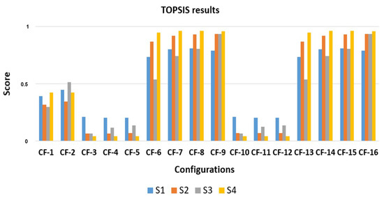
Figure 9.
Illustrative results obtained by TOPSIS method.
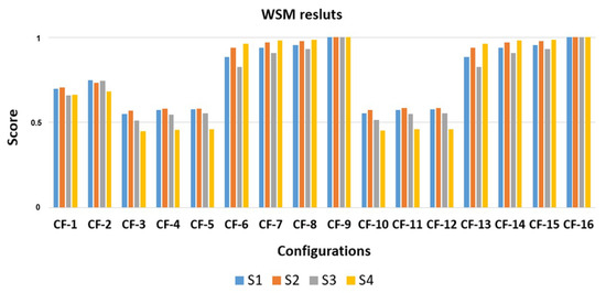
Figure 10.
Illustrative results obtained by WSM method.
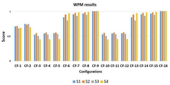
Figure 11.
Illustrative results obtained by WPM method.
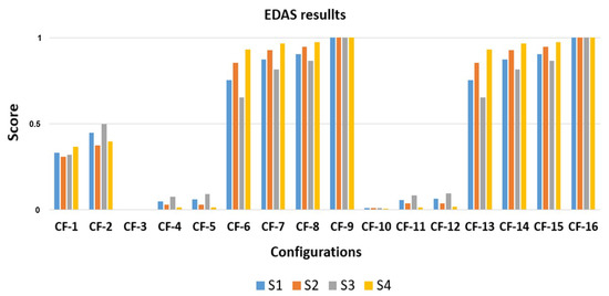
Figure 12.
Illustrative results obtained by EDAS method.
The legends “S1”, “S2”, “S3”, and ”S4” presented in these four figures refer, respectively, to scenarios 1, 2, 3, and 4 presented in Table 2.
Out of the 16 different configurations, there are 10 that involve shared production. According to Figure 9, Figure 10, Figure 11 and Figure 12, these 10 configurations consistently score better than the other configurations across all methods and scenarios. For instance, in decision matrix , a comparison between configurations CF-4 and CF-9 indicates that CF-9 provides significant benefits in terms of economic gain (an increase of 64.71%), reduced CO2 emissions (a decrease of 26.95%), greater self-sufficiency (an increase of 21.39%), and job creation (an increase of 175.24%).
Figure 9, Figure 10, Figure 11 and Figure 12 illustrate that the configurations which include either individual or collective storage receive a better score compared to those without storage, across all methods and scenarios. Furthermore, the results suggest that collective storage outperforms individual storage. The primary advantage of adding either individual or collective storage is an increase in self-sufficiency, which is the most notable benefit.
For all methods and scenarios, the CF-16 configuration that merges individual and collective self-consumption, individual and collective storage, and the incorporation of energy interchange among factories give the best score. The second-best configuration is CF-9, which is identical to CF-16 except it lacks energy exchange between factories. When deciding between the two best configurations, it may be preferable to select the configuration that lacks energy exchange between factories for two reasons. First, the difference in performance between the two configurations, as indicated by the results in matrix for the four criteria, is negligible, with a difference of less than 0.1%. Second, opting for the simpler configuration can streamline network management and reduce its overall complexity.
8. Conclusions and Perspectives
This article proposed 16 configurations divided into five categories for a renewable energy community and compared them based on four criteria, namely economic, environmental, technical, and social. For this purpose, a mathematical model is developed for each configuration, and solved by IBM ILOG CPLEX Optimization Studio solver using four different objectives. Then, four MCDM methods were used to find the best configuration(s) based on four considered criteria. An evaluation of the performance has also been made between different MCDM methods using four different scenarios. The findings indicate that configurations that combine both individual and collective energy self-consumption perform the best according to different criteria. Specifically, the CF-16 and CF-9 configurations obtain the highest scores by the four MCDM methods used and across four different scenarios. The results also demonstrate the significance of incorporating collective energy production to enhance economic benefits and minimize CO2 emissions. For instance, the CF-9 configuration offers substantial advantages over the CF-4 configuration, including a 64.71% increase in economic gains, a 26.95% decrease in CO2 emissions, a 21.39% increase in self-sufficiency, and a 175.24% increase in job creation. Moreover, the inclusion of individual and/or collective energy storage improves the outcomes and boosts community self-sufficiency rates. For example, in the CT-3 and CT-5 categories, the configurations with storage systems witness a 12.95% increase in self-sufficiency compared to others. This increase enables the energy community to be less reliant on the power grid, leading to a substantial decrease in CO2 emissions.
In future work, it could be interesting to propose a clustering method for classifying factories into groups to choose the best configuration of energy self-consumption that maximizes the benefits of each factory.
Author Contributions
Methodology, H.G., M.M.A. and F.Y.; Software, H.G. and M.M.A.; Investigation, H.G. and M.M.A.; Writing—original draft, H.G.; Writing—review & editing, H.G., M.M.A. and F.Y.; Supervision, M.M.A. and F.Y.; Project administration, H.G., M.M.A. and F.Y. All authors have read and agreed to the published version of the manuscript.
Funding
This paper was funded by the Région Grand Est, France.
Data Availability Statement
The data presented in this study are available on request from the corresponding author.
Conflicts of Interest
The authors declare no conflict of interest.
Appendix A

Table A1.
Constraints of the configuration models.
Table A1.
Constraints of the configuration models.
| Configurations | Constraints | |
|---|---|---|
| CT-1 | CF-1 | : Demand satisfaction : Capacity of shared production : Percentage of contribution |
| CF-2 | : Demand satisfaction : Capacity of shared production : Percentage of contribution Constraints of the shared battery → Section 4.6 | |
| CT-2 | CF-3 | : Demand satisfaction : Capacity of factories production |
| CF-4 | : Demand satisfaction : Capacity of factories production Constraints of the factories batteries → Section 4.5 | |
| CF-5 | : Demand satisfaction : Capacity of factories production Constraints of the shared battery → Section 4.6 | |
| CT-3 | CF-6 | : Demand satisfaction : Capacity of factories production : Capacity of shared production : Percentage of contribution |
| CF-7 | : Demand satisfaction : Capacity of factories production : Capacity of shared production : Percentage of contribution Constraints of the factories batteries → Section 4.5 | |
| CF-8 | : Demand satisfaction : Capacity of factories production : Capacity of shared production : Percentage of contribution Constraints of the shared battery → Section 4.6 | |
| CF-9 | : Demand satisfaction : Capacity of factories production : Capacity of shared production : Percentage of contribution Constraints of the shared battery → Section 4.6 Constraints of the factories batteries → Section 4.5 | |
| CT-4 | CF-10 | : Demand satisfaction : Capacity of factories production |
| CF-11 | : Demand satisfaction : Capacity of factories production Constraints of the factories batteries → Section 4.5 | |
| CF-12 | : Demand satisfaction : Capacity of factories production Constraints of the shared battery → Section 4.6 | |
| CT-5 | CF-13 | : Demand satisfaction : Capacity of factories production : Capacity of shared production : Percentage of contribution |
| CF-14 | : Demand satisfaction : Capacity of factories production : Capacity of shared production : Percentage of contribution Constraints of the factories batteries → Section 4.5 | |
| CF-15 | : Demand satisfaction : Capacity of factories production : Capacity of shared production : Percentage of contribution Constraints of the shared battery → Section 4.6 | |
| CF-16 | : Demand satisfaction : Capacity of factories production : Capacity of shared production : Percentage of contribution Constraints of the shared battery → Section 4.6 Constraints of the factories batteries → Section 4.5 |
References
- Falkner, R. The Paris Agreement and the new logic of international climate politics. Int. Aff. 2016, 92, 1107–1125. [Google Scholar] [CrossRef]
- Li, H.; Qin, Q. Challenges for China’s carbon emissions peaking in 2030: A decomposition and decoupling analysis. J. Clean. Prod. 2019, 207, 857–865. [Google Scholar] [CrossRef]
- Caramizaru, A.; Uihlein, A. Energy communities: An Overview of Energy and Social Innovation; Publications Office of the European Union: Luxembourg, 2020; Volume 30083. [Google Scholar]
- Gjorgievski, V.; Cundeva, S.; Georghiou, G. Social arrangements, technical designs and impacts of energy communities: A review. Renew. Energy 2021, 169, 1138–1156. [Google Scholar] [CrossRef]
- Cosic, A.; Stadler, M.; Mansoor, M.; Zellinger, M. Mixed-integer linear programming based optimization strategies for renewable energy communities. Energy 2021, 237, 121559. [Google Scholar] [CrossRef]
- Liu, J.; Chen, X.; Yang, H.; Shan, K. Hybrid renewable energy applications in zero-energy buildings and communities integrating battery and hydrogen vehicle storage. Appl. Energy 2021, 290, 116733. [Google Scholar] [CrossRef]
- Rehman, H.; Reda, F.; Paiho, S.; Hasan, A. Towards positive energy communities at high latitudes. Energy Convers. Manag. 2019, 196, 175–195. [Google Scholar] [CrossRef]
- Ceglia, F.; Esposito, P.; Faraudello, A.; Marrasso, E.; Rossi, P.; Sasso, M. An energy, environmental, management and economic analysis of energy efficient system towards renewable energy community: The case study of multi-purpose energy community. J. Clean. Prod. 2022, 369, 133269. [Google Scholar] [CrossRef]
- Alonso, A.; Hoz, J.; Martin, H.; Coronas, S.; Matas, J. Individual vs. Community: Economic Assessment of Energy Management Systems under Different Regulatory Frameworks. Energies 2021, 14, 676. [Google Scholar] [CrossRef]
- Vivian, J.; Chinello, M.; Zarrella, A.; De Carli, M. Investigation on Individual and Collective PV Self-Consumption for a Fifth Generation District Heating Network. Energies 2022, 15, 1022. [Google Scholar] [CrossRef]
- Pulazza, G.; Orozco, C.; Borghetti, A.; Tossani, F.; Napolitano, F. Procurement cost minimization of an energy community with biogas, photovoltaic and storage units. In Proceedings of the 2021 IEEE Madrid PowerTech, Madrid, Spain, 28 June 2021–2 July 2021; pp. 1–6. [Google Scholar]
- Spertino, F.; Ciocia, A.; Di Leo, P.; Fichera, S.; Malgaroli, G.; Ratclif, A. Toward the complete self-sufficiency of an NZEBS microgrid by photovoltaic generators and heat pumps: Methods and applications. IEEE Trans. Ind. Appl. 2019, 55, 7028–7040. [Google Scholar] [CrossRef]
- Gribiss, H.; Aghelinejad, M.; Yalaoui, F. A New Strategy for Collective Energy Self-consumption in the Eco-Industrial Park: Mathematical Modeling and Economic Evaluation. In Proceedings of the International Conference On Metaheuristics And Nature Inspired Computing, Marrakech, Morocco, 27–30 October 2021; pp. 212–225. [Google Scholar]
- Siksnelyte, I.; Zavadskas, E.; Streimikiene, D.; Sharma, D. An overview of multi-criteria decision-making methods in dealing with sustainable energy development issues. Energies 2018, 11, 2754. [Google Scholar] [CrossRef]
- Kumar, A.; Sah, B.; Singh, A.; Deng, Y.; He, X.; Kumar, P.; Bansal, R. A review of multi criteria decision making (MCDM) towards sustainable renewable energy development. Renew. Sustain. Energy Rev. 2017, 69, 596–609. [Google Scholar] [CrossRef]
- Wang, C.; Huang, Y.; Chai, Y.; Nguyen, V. A multi-criteria decision making (MCDM) for renewable energy plants location selection in Vietnam under a fuzzy environment. Appl. Sci. 2018, 8, 2069. [Google Scholar] [CrossRef]
- Salameh, T.; Sayed, E.; Abdelkareem, M.; Olabi, A.; Rezk, H. Optimal selection and management of hybrid renewable energy System: Neom city as a case study. Energy Convers. Manag. 2021, 244, 114434. [Google Scholar] [CrossRef]
- Van Alphen, K.; Sark, W.; Hekkert, M. Renewable energy technologies in the Maldives—determining the potential. Renew. Sustain. Energy Rev. 2007, 11, 1650–1674. [Google Scholar] [CrossRef]
- Gribiss, H.; Aghelinejad, M.; Yalaoui, F. Economic and environmental evaluations of photovoltaic installations for self-consumption in industrial energy communities. IFAC-PapersOnLine 2022, 55, 1471–1476. [Google Scholar] [CrossRef]
- Cucchiella, F.; D’Adamo, I.; Gastaldi, M. Economic analysis of a photovoltaic system: A resource for residential households. Energies 2017, 10, 814. [Google Scholar] [CrossRef]
- Franzoi, N.; Prada, A.; Verones, S.; Baggio, P. Enhancing PV self-consumption through energy communities in heating-dominated climates. Energies 2021, 14, 4165. [Google Scholar] [CrossRef]
- Sokolnikova, P.; Lombardi, P.; Arendarski, B.; Suslov, K.; Pantaleo, A.; Kranhold, M.; Komarnicki, P. Net-zero multi-energy systems for Siberian rural communities: A methodology to size thermal and electric storage units. Renew. Energy 2020, 155, 979–989. [Google Scholar] [CrossRef]
- Hannan, M.; Wali, S.; Ker, P.; Abd Rahman, M.; Mansor, M.; Ramachandaramurthy, V.; Muttaqi, K.; Mahlia, T.; Dong, Z. Battery energy-storage system: A review of technologies, optimization objectives, constraints, approaches, and outstanding issues. J. Energy Storage 2021, 42, 103023. [Google Scholar] [CrossRef]
- Cielo, A.; Margiaria, P.; Lazzeroni, P.; Mariuzzo, I.; Repetto, M. Renewable Energy Communities business models under the 2020 Italian regulation. J. Clean. Prod. 2021, 316, 128217. [Google Scholar] [CrossRef]
- Pedrero, J.; Hernandez, P.; Martinez, A. Economic Evaluation of PV Installations for Self-Consumption in Industrial Parks. Energies 2021, 14, 728. [Google Scholar] [CrossRef]
- PVGIS. Available online: https://re.jrc.ec.europa.eu/pvg_tools/fr/ (accessed on 12 June 2022).
- Ozturk, H. Energy usage and cost in textile industry: A case study for Turkey. Energy 2005, 30, 2424–2446. [Google Scholar] [CrossRef]
- Tzeng, G.; Huang, J. Multiple Attribute Decision Making: Methods and Applications; CRC Press: Boca Raton, FL, USA, 2011. [Google Scholar]
- Kumar, A.; Singh, A.; Deng, Y.; He, X.; Kumar, P.; Bansal, R. Integrated assessment of a sustainable microgrid for a remote village in hilly region. Energy Convers. Manag. 2019, 180, 4420–4472. [Google Scholar] [CrossRef]
Disclaimer/Publisher’s Note: The statements, opinions and data contained in all publications are solely those of the individual author(s) and contributor(s) and not of MDPI and/or the editor(s). MDPI and/or the editor(s) disclaim responsibility for any injury to people or property resulting from any ideas, methods, instructions or products referred to in the content. |
© 2023 by the authors. Licensee MDPI, Basel, Switzerland. This article is an open access article distributed under the terms and conditions of the Creative Commons Attribution (CC BY) license (https://creativecommons.org/licenses/by/4.0/).