Article

Hydrogen Production by Steam Reforming of Pyrolysis Oil from Waste Plastic over 3 wt.% Ni/Ce-Zr-Mg/Al2O3 Catalyst

1
Department of Environment-Energy Engineering, The University of Suwon, 17 Wauan-gil, Hwaseong-si 18323, Republic of Korea
2
Bio Friends Inc., Yuseong-gu, Daejeon 34028, Republic of Korea
*
Author to whom correspondence should be addressed.
Energies 2023, 16(6), 2656; https://doi.org/10.3390/en16062656
Submission received: 1 February 2023 / Revised: 1 March 2023 / Accepted: 7 March 2023 / Published: 12 March 2023

Abstract

:
Sustained increase in plastic use has placed a significant burden on waste disposal infrastructure. Pyrolysis is the process of decomposing high-molecular-weight compounds by heating waste plastics at 500–1000 °C without oxygen. This process considerably reduces greenhouse gas emissions and has a high alternative energy effect (0.57 TOE ton−1). After a separation process, the oil produced by pyrolysis (C5–C20) can yield naphtha oil (C6–C7). Subsequently, hydrogen can be produced through a reforming reaction of this naphtha oil. Here, we produced hydrogen from waste plastic pyrolysis oil over a Ni/Ce-Zr-Mg/Al2O3 catalyst using a steam reforming process. A model oil combining the major substances of C6 and C7 (hexane, hexene, heptane, heptene, and toluene) was formed. From the reaction products, the hydrogen yield was obtained based on analysis of H2, CO, and CO2 concentrations using gas chromatography. The effect of N2 and O2 addition on hydrogen yield was analyzed within a temperature range of 750–850 °C, steam/carbon (S/C) ratio of 0.6–4, and space velocity of 7600–19,100 h−1. In addition, a durability test was performed using 3 wt.% Ni/Ce-Zr-Mg/Al2O3 catalysts for 100 h; a hydrogen yield of 91.3% was maintained from the refined waste plastic oil.

1. Introduction

A recent surge in single-use plastics resulting from contactless technologies and the COVID-19 pandemic is threatening international environmental standards and contributing to various social problems. Reductions in the generation of plastic waste are fundamental to circular economy and carbon neutrality strategies. Processing mixed waste plastic is challenging. Recently, waste plastic pyrolysis and chemical recycling technologies have attracted interest for dealing with plastic waste and reducing greenhouse gas emissions from incineration. Chemical recycling refers to the process of transforming a macromolecule plastic into a monomer or polymer state through pyrolysis or chemical reaction [1]. Pyrolysis, a representative technology of chemical recycling, involves a chemical reaction that transforms plastic through redox decomposition under mid-high temperatures (400–600 °C) and without oxygen conditions into low-molecular-weight compounds [2], and produces gas or oil.
The major plastic types include LDPE (low-density polyethylene), PP (polypropylen), PVC (polyvinyl chloride), HDPE (high-density polyethylene), PS (polystyrene), PET (polyethylene terephthalate), ABS (acrylonitrile butadiene styrene copolymer), and EPS (expanded polystyrene), among others. Thermoplastic PET is extensively used in textiles, film, and beverage bottles, and is a major cause of plastic waste [3]. When mixed plastic is processed using waste plastic pyrolysis, the quality of the recycled plastic is similar to that of crude oil-based plastic [4]. Greenhouse gases are emitted during the production, usage, and discarding processes of petroleum-based plastics. In the European Union, demand for recycled naphtha has increased and regulations for waste plastic have become more stringent. By 2030, all nations aim to have prioritized chemical recycling to reduce major greenhouse gas emissions through decarbonization of the industrial sector [5].
As a recyclable supply material, hydrogen production through direct reforming has the advantage of being able to utilize CO2, as opposed to methods such as partial oxidation(POX) or steam reforming (SR). In general, the SR process under high temperatures (700–1000 °C) does not require oxygen input; unlike POX and ATR, the operating temperature of the reactor is low, and a mixed gas of H2 and CO in a 3:1 ratio is produced. For hydrogen production, SR is generally applied in industries owing to its high thermal efficiency (up to 85%). To begin the reaction, energy input is required and the process involves an endothermic method that does not require oxygen gas. H2 is mainly formed by SR natural gas, naphtha, and light hydrocarbon. Using biomass such as waste plastic is carbon-neutral; moreover, it offers an efficient and green solution, as the sulfur content is low. Hydrogen production is available with catalysts [6,7]. Dry reforming of hydrocarbons requires high temperatures (700~1000 °C) due to a highly endothermic reaction [8,9]. One of the advantages is the operation at atmospheric pressure, hence the process does not require equipment to maintain high pressure. The production of syngas from the dry reforming of hydrocarbon is influenced by the simultaneous occurrence of side reactions, including the reverse water–gas shift (RWGS) reaction. Due to the low enthalpy, it is thermodynamically advantageous, but the hydrogen generated by the RWGS reaction is consumed and the H2/CO ratio is lowered due to the production of carbon oxides. In addition, one of the technical challenges in the DR reaction is the inactivation of the catalyst due to carbon deposition or sintering of the Ni catalyst [10,11].
Bona et al. [12] compared hydrogen production from SR in toluene using the Ni/Al catalyst in a reaction where no catalysts were used. In this reaction, the carbon conversion rate was only 3.7%, compared with 56.4% for the Ni/Al catalyst reaction. In addition, a conversion rate of 71.6% was observed from the Ni/Co/Al catalyst, and a higher rate of 75.8% was reached in the Ni/Al/La catalyst reaction where La was added. Thus, the use of Ni/Al-type catalysts is advantageous for reforming C7 (toluene).
Kontchouo et al. [13] reported impacts of structural difference of aliphatic and aromatic hydrocarbon from steam reforming of toluene and n-hexane over Ni/SBA-15 catalyst. The linear chain structure of n-hexane and the low methane yield in the steam reforming of toluene made the decomposition of the aliphatic chain of n-hexane more likely to produce CH4. Cracking of the aliphatic chain of n-hexane will form abundant CHx species, and reaction with hydrogen radicals can readily form CH4. In contrast, toluene has only one methyl group superconjugated to the benzene ring. As a result, a low yield of methane was formed. The CO yield increased exponentially between 550 and 750 °C for both steam reforming of toluene and n-hexane. This rapid increase in CO yield may be caused by the revers water–gas shift (rWGS) reaction or coke gasification by CO2.
The catalyst treatment process is comprised of the catalyst, catalyst support, and catalyst promoter stages. Precious metal catalysts for reforming reactions (e.g., Ru, Rh, Pd, and Pt) have high activation and resistivity to carbon deposition; however, the cost is also high. Catalysts with Ni, Co, or Fe (as) active materials show similar activation to precious metal catalysts; however, Ni-based materials may exhibit sudden deactivation due to carbon formation and sintering [14]. Both precious and nonprecious reactive metals are used as catalysts, and precious metals are also used as promoters. The use of Ni catalysts in the SR reaction is commercialized at the industrial scale. In addition, a number of studies have reported that Ni is the most suitable metal for the SR of hydrocarbons such as ethanol [15,16]. Ni-based catalysts are often used in reforming reactions due to their low cost compared with precious metals [17,18]. Ni not only shows the ability to disintegrate C-C coupling but also has high methanation activation [19].
Dispersion of a small amount of a catalyst substance to provide catalyst support can contribute to activation of the catalyst [20]. Generally, Al2O3, TiO2, SiO2, and ZrO2 are used as Ni-based catalyst supports. Among these, Al2O3 is a low-cost, porous support material with a high specific surface area; as such, a homogeneous dispersion effect of Ni on the catalyst surface is expected [21,22,23,24]. If the density between electrons within the metals increases, the promotion of oxidation–reduction owing to electron movement between the supporting and activated metals can promote the formation of CH4 and destruction of the C=O bond by improving the bond between Ni and C [25]. Physicochemical characteristics of other supporters can significantly affect surface characteristics, the size of the Ni crystal, catalyst properties, and the reducing property of the catalyst.
Promoters containing oxygen (e.g., CeO2 and ZrO2) can prevent carbon deposition when Ni- or CO- catalysts are used [26]. CeO2 is highly stable, shows strong adsorption capacity and oxygen storage capacity, and results in high activation [27,28]. ZrO2 prevents both the reduction of NiO into Ni metal and the transformation of inactive NiAl2O4 [29]. Carbon is known to form on surfaces where the carrier is acidic and has been reported to potentially exhibit good catalyst performance by improving the resistivity to carbon formation when using basic promoters (CaO and MgO). In particular, the addition of MgO could enhance the dispersion of the catalyst and acidity near Ni within the catalyst. Therefore, MgO could prevent the agglomeration of the active site of Ni or carbon deposition on the surface of catalysts [30,31].
Nickel catalysts possessing reasonably high catalytic activity and cheap cost have been widely used in methane reforming, being supported on many metal oxides, such as Al2O3, MgO, CeO2, or La2O3 [32]. Nevertheless, the major drawbacks of Ni-based catalysts are their rapid deactivation and low stability due to coke deposition and the sintering of Ni components. Bimetallic catalysts have been found to exhibit better performance than corresponding monometallic systems, probably due to their activity, stability, and coke resistivity [33]. Therefore, some other transition metal additives (Fe, Co, Pd, Ru, Pt) [34,35,36] and supports have been applied to improve the performance of Ni-based catalysts.
Several studies have demonstrated that the threshold nickel nanoparticle size affects carbon formation; for non-noble metals, in fact, the rate of methane dissociation exceeds the rate of the oxidation bringing to the carbon formation on the metal as filaments. The rate of carbon formation is proportional to the nickel particle size, hence, for a size below 2 nm, the carbon formation significantly slows down [37]. Most researchers have prepared 10–20% Ni content of the catalyst for the reforming reaction activity. As the Ni content increases, the catalyst agglomerates or sinters in the process of calcination and reaction, so the nickel particle size increases and the specific surface area of the catalyst tends to decrease.
The aim of this study is to reduce the Ni content to 3 wt% and to manufacture a small nickel particle size to prevent particle agglomeration for high-temperature calcination and reaction, thereby minimizing carbon deposition. Ni metal is relatively cheap, the Ce component has high oxygen storage capacity, the Zr component has high redox reaction ability because it has acid–base properties at the same time, and MgO prevents carbon deposition and improves Ni dispersion. By impregnating these components into an Al2O3 carrier with a large surface area, a Ni/Ce-ZrO2/MgO-Al2O3 catalyst with excellent durability and high temperature resistance in reforming reactions is prepared. In particular, conditions such as temperature, space velocity, and steam/carbon (S/C) ratio play an important role in the reforming reaction of C6–C7 oil from the pyrolysis of waste plastic. It is to find conditions that can maximize hydrogen yield and minimize unreacted materials at the same time.

2. Materials and Methods

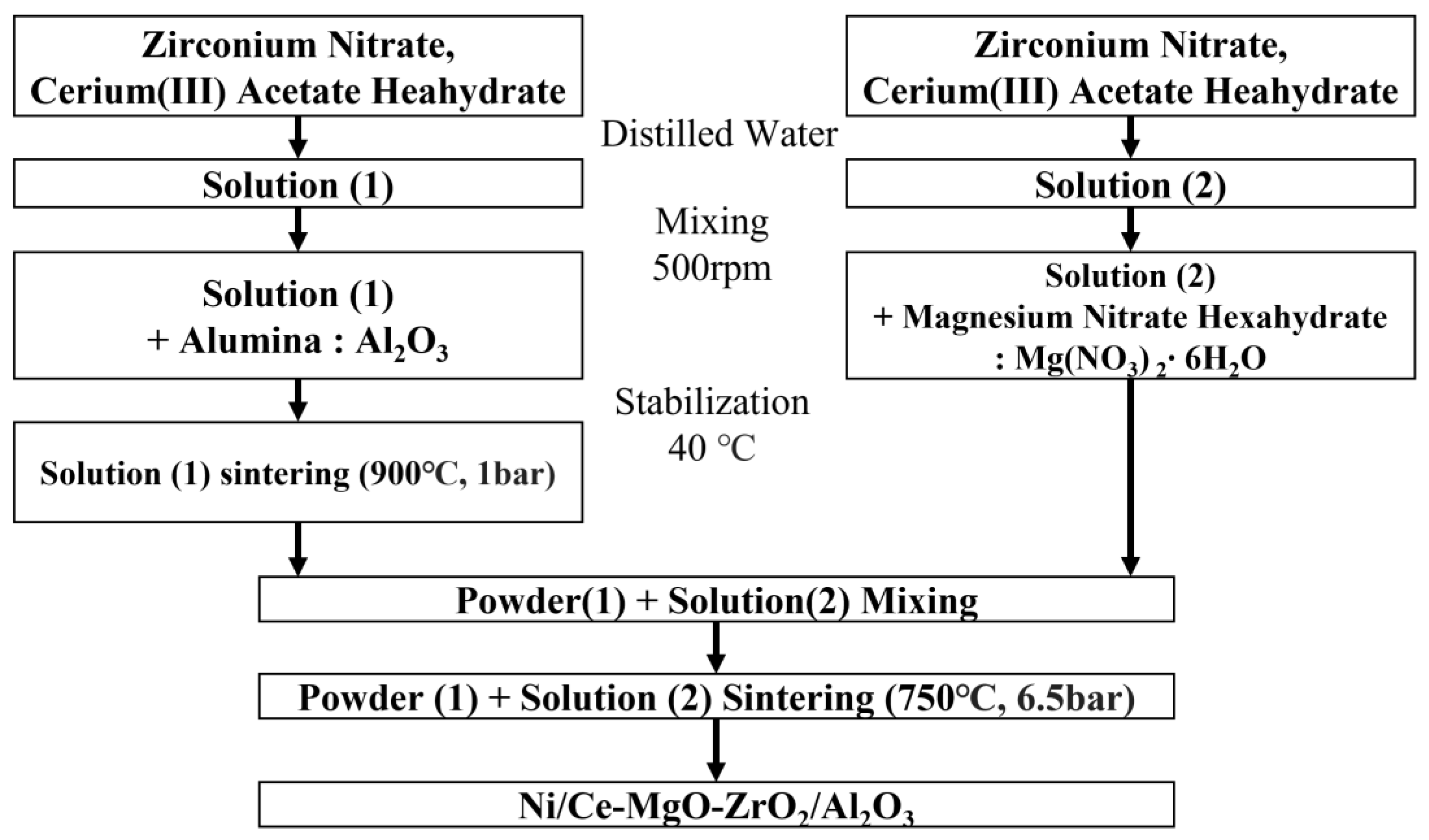
2.1. Catalyst Preparation

The catalyst used in the present study was prepared by Ni-ɤAl2O3 to produce 3 wt.% Ni/Ce-Zr-Mg/Al2O3 (Figure 1), and the zirconium nitrate (Zr(NO3)4) and cerium acetate solution (CH3CO2)3Ce·6H2O) were loaded into a slurry-state. Solution (1) was created by mixing uniformly at ~500 rpm, stabilizing at 40 °C, and then putting the ɤ-alumina ball in the Ce-ZrO2 solution, then leaving it for 60 min. The ɤ-alumina solution was evaporated using an evaporator at 40 °C and 90 rpm for 60 min, and then heated for 3 h at 900 °C (5 °C/min) in a furnace to obtain powder. Thereafter, Ni (II) nitrate solution and magnesium nitrate were mixed to produce a slurry-state solution (solution 2). Solution (2) was impregnated into powder (1) and heated for 6.5 h at 750 °C (3 °C/min) in a furnace to produce the catalyst Ni/Ce-Mg-Zr/Al2O3.

2.2. Catalyst Analysis

To analyze the properties of the 3 wt.% Ni/Ce-Zr-Mg/Al2O3 catalyst surface, the specific surface area during the physisorption of N2 (−196 °C) at 300°C was measured using the Brunauer–Emmett–Teller (BET) method. The catalyst surface was characterized by BET (ASAP2020 Plus version 1.02, Micromeritics, Norcross, United States) at the center for advanced materials analysis at Suwon University. The surface and composition of the catalyst were identified using SEM (FEI-Apreo Scanning Electron Microscope, Thermo Fisher Scientific, Waltham, MA, USA). Subsequently, the catalyst was desiccated for ~1 h at 120 °C and coated with metal (Au) for measurement at a voltage of 10 kV with a Mode2 (Detector T1, T2). X-ray diffraction (XRD) was used to analyze the catalyst compositions using a Philips Xpert Power Diffractometer and PAN analytical(USA) at the Center for Advanced Materials Analysis, Suwon University. The catalyst specimen powder was pretreated for ~5 h at 250 °C to remove moisture under a N2 gas flow. Measurements were performed using Cu-Kα radiation, scanning speed of 8 θ min−1, 2θ range of 10–80°, beam conditions of 30 mA and 40 kV, and a fixed specimen axis of 5°. Catalyst-binding energies before and after the reaction were analyzed using X-ray photoelectron spectroscopy (XPS, Thermo Fisher Scientific, K-Alpha plus model). The thermal stability of the catalyst was measured using a TGA (TGA 4000, Perkin Elmer, Waltham, MA, USA) by increasing from 30 °C to 900 °C at a rate of 10 °C min−1.

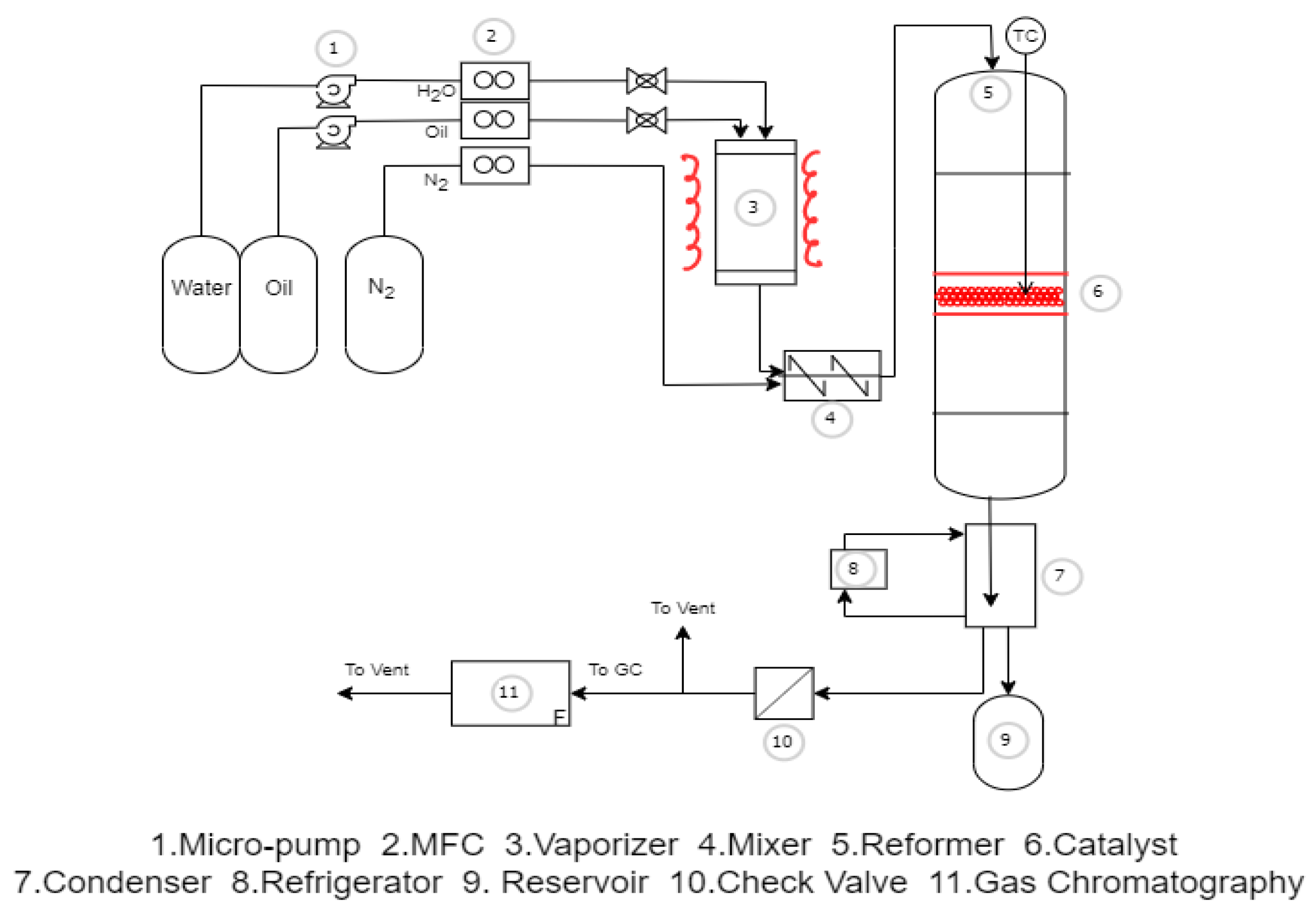
2.3. Experimental Method and Procedures

The experimental equipment used in the present study is shown in Figure 2. At the bottom of the reactor, the Ni catalyst was charged with the plug-flow system (PFS) before increasing the temperature to the desired extent using the heater. First, a mesh net and quartz wool were layered at the bottom of the reactor and filled with ~1 g of catalyst. Then, a k-type sensor was installed to measure the temperature. The reaction product of the liquid oil and water was quantitatively supplied to about 160 °C vaporizer using the micropump and the vaporized mixed model oil was injected into the reactor. The reaction product gas was analyzed in the gas chromatograph after removing nonreactants and water in the cold trap (~2 °C). The products were analyzed with a YL Instrument 6500 System(Anyang, Republic of Korea); two channel columns were an SS COL 10FT 1/8″ PORAPACK N (Model: 13052-U) and Phase None, Matrix 45/60 Molecular Sieve 13X. Hydrogen, methane, and carbon monoxide were analyzed using a thermal conductivity detector (TCD), and carbon dioxide was analyzed using a flame ionization detector (FID) with a CO2 methanizer. The gas chromatography (GC) oven temperature was maintained at 35 °C for 0–6 min, and the temperature was increased to ~170 °C at a rate of 15 °C min−1. For the FID, hydrogen and oxygen were injected at 35 and 300 mL min−1, respectively, at a temperature of 250 °C. For the TCD, hydrogen and argon were injected at 35 and 20 mL min−1, respectively, at a temperature of 150 °C. The byproduct and nonreactants of the liquid oil were analyzed using the capillary column of GS-Carbonplot.
Among C6–C7, substances presented in proportions of 1.5 mol% or more were selected to create mixed model oils (Table 1) and used as reactants.
Experimental conditions (Table 2) used to ascertain the impact in hydrogen yield included reaction temperatures of 750–850 °C under atmospheric conditions, space velocity of 7600–19,100 h−1, and a S/C ratio of 0.6–4.
The gas that flowed through the reactor was analyzed using the GC, and the hydrogen yield and carbon conversion rate were determined by the following Equations (1) and (2).
Y H 2   =   [ H 2 ] out [ H Steam , i n ] + 4 [ H oil ,   i n ] × 100
X C = C oil ,   i n C oil ,   out C oil ,   i n × 100
where XH2 denotes hydrogen yield, XC denotes carbon conversion, Hsteam denotes hydrogen in steam, and COil denotes carbons in oil.

3. Results and Discussion

3.1. Catalyst Characterization

3.1.1. Specific Surface Area

The surface area, pore volume, and pore size before (Fresh) and after (Spent) the reaction are shown in Table 3. The Brunauer, Emmett, and Teller (BET) specific surface area of the used catalyst increased in comparison with the fresh catalyst. Similar tendencies were identified by Achouri et al. [39], indicating that catalyst sintering did not occur and that there was no particle damage or experimental error. As shown by the thermogravimetric analyzer (TGA), carbon was generated in the catalyst after the reaction, indicating an increase in the BET specific surface area.

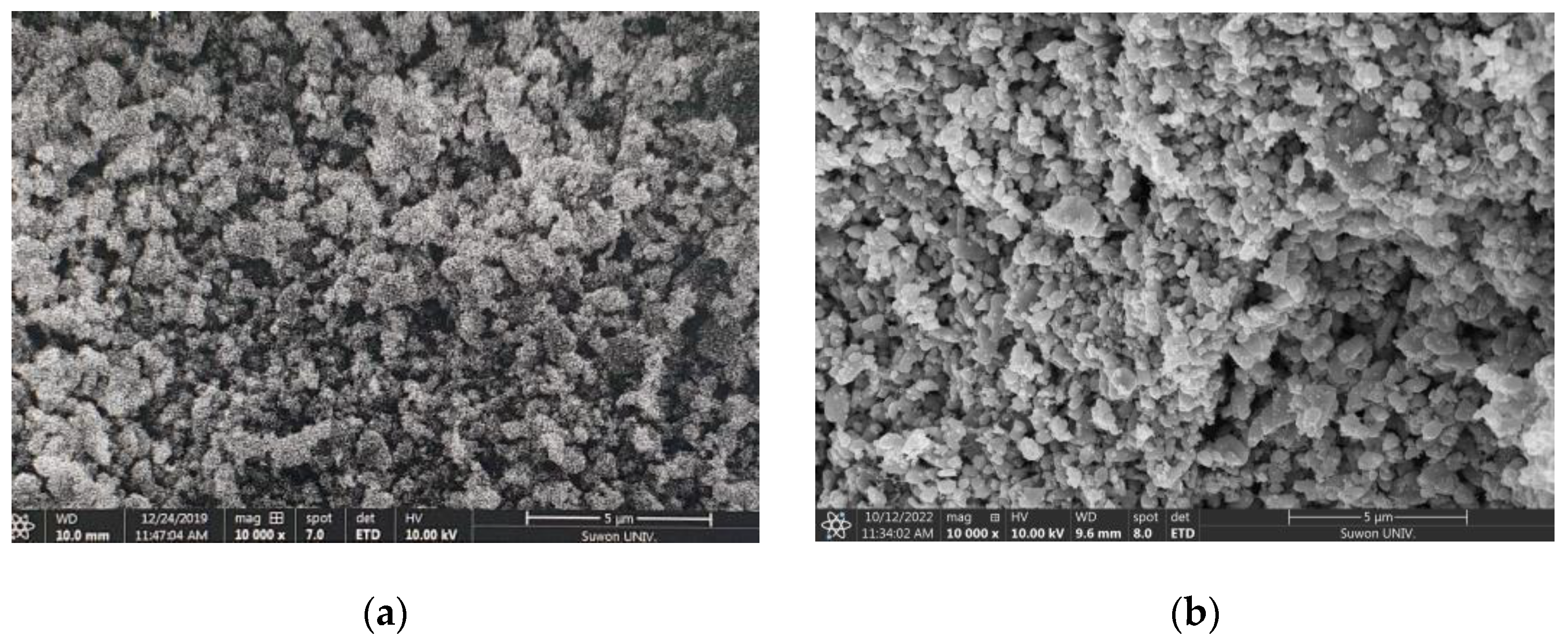
3.1.2. Scanning Electron Microscopy

SEM images at a magnification of 10,000× are shown in Figure 3. The catalyst particles were similarly distributed before and after the reaction, and there seems to be little difference in the sintered crystallinity of the fresh catalyst and the spent catalyst, which were tested for activity over 100 h.
Table 4 summarizes the composition of the catalyst determined by ICP-OES. The contents of Ce and MgO in the catalyst decreased slightly, while those of NiO and Zr remained consistent after reforming.

3.1.3. X-ray Diffraction

XRD analysis results before and after the reaction are shown in Figure 4. The 2θ diffraction peaks occurred at 20°, 32°, 37.3°, and 62.9° and were related to NiO, and those at 44.55° and 78.3° were related to Ni metal. The 2θ peaks at 36.9°, 45.86°, and 66.91° were related to MgO, and those at 37.4°, 46.07°, 58.8°, and 66.9° were related to Al2O3. XRD spectra were similar before and after the reaction (Figure 4). The main activation points of the NiO peaks were most pronounced when 2θ = 20°, 32°and 37.3° in both the Fresh and Spent catalysts [40,41].

3.1.4. X-ray Photoelectron Spectroscopy

The XPS analysis results are shown in Figure 5. Peak locations of the Spent catalyst were compared using the NIST database, and the 49.67, 72.45, and 530.65 eV peaks were allocated to Mg1P, Al2P, and O1S, respectively. No new peaks were observed compared with the Fresh catalyst; however, the C1s spectrum was more pronounced after the reforming reaction. The C1s spectrum has three peaks at 285.4 eV, 286.9 eV, and 289.4 eV, attributed to bulk-bonded carbons C-C, CO chemical bonds, and C=O bonds. It was analyzed that carbon was produced after the reaction in SEM-EDAX (Table 4) and TGA (Figure 6) data, and the C1s peak of XPS is expected to be carbon deposition. These results were consistent with the experimental results reported by Li, QX et al. [42]. The main cause of catalyst deactivation was the reflecting carbon deposition, which was increased by the carbon content on the catalyst surface during SR. This can be confirmed in the TGA result that carbon is converted to CO2 and a peak occurs.

3.1.5. Thermogravimetric Analysis

The results of TGA analysis before and after the reaction are shown in Figure 6. Almost no mass change was observed in the Fresh catalyst. In the Spent catalyst, a mass reduction of ~3 wt.% began at ~571 °C following 100 h of reaction. The mass reduction was volatile due to the reaction of carbon deposited on the catalyst with oxygen in the air [13].

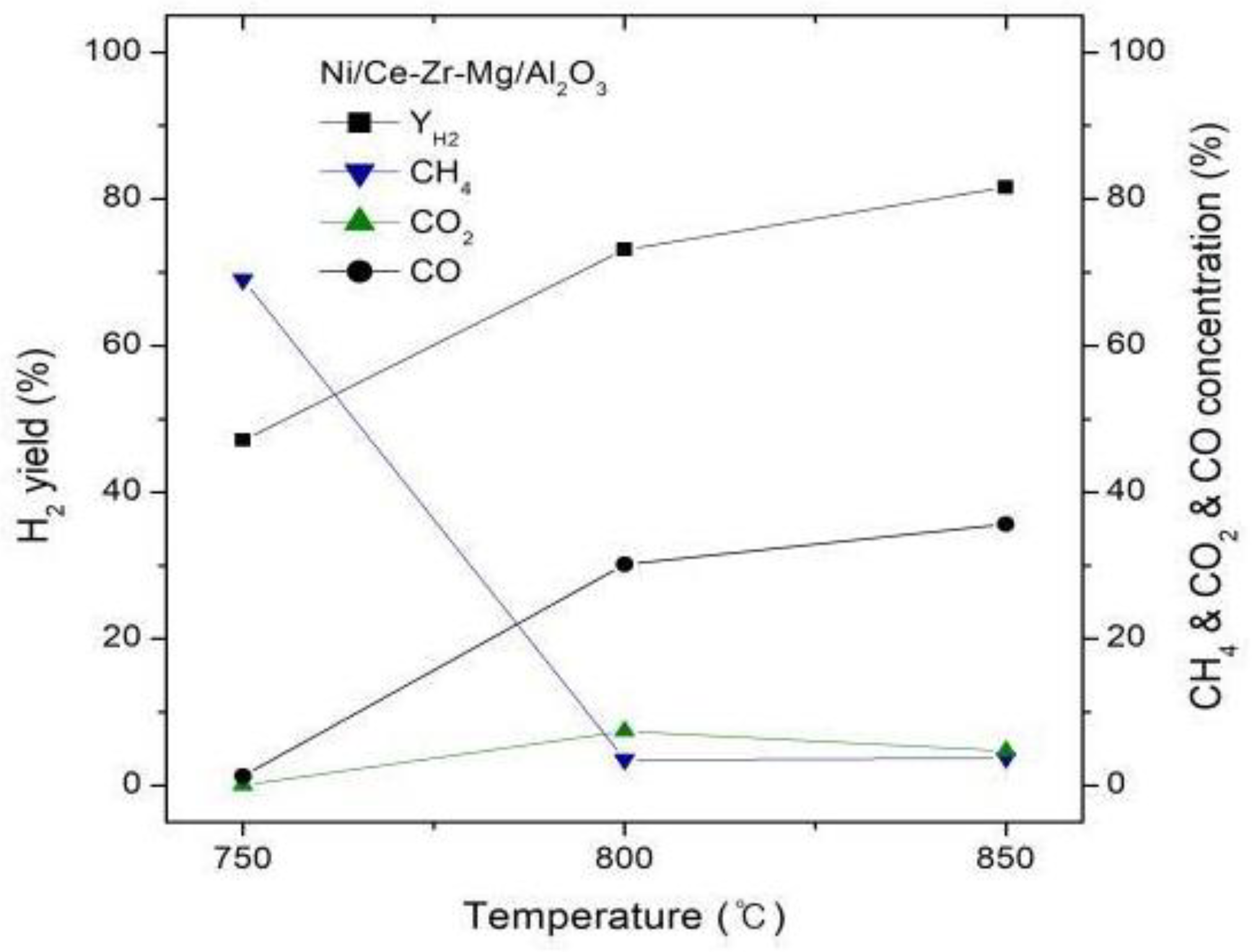
3.2. Effect of Temperature on Hydrogen Yield

As shown in Figure 7, hydrogen yield, CO, and CO2 increased with increasing experimental temperature, while CH4 concentration rapidly decreased. This implies that the reaction temperature significantly impacted catalyst reactivity and stability. The higher the reaction temperature, the more advantageous it is for heat absorption of the SR process, hydrocarbon decomposition from H2O and CO2, and oxidation of the carbon intermediate [43]. Gaseous products were produced in the order of H2 > CO > CO2 > CH4. H2 yield increased rapidly from 43% to 81% (750–850 °C), and CO yield increased from 1% to 36%, whereas CH4 yield decreased significantly from 70% to 1%, or below. The phenomena can occur more favorably during the reaction between CO2 and H2O and carbon deposition because the reaction temperature is higher. These results are similar to those reported by Yoon et al. [44] for toluene activation. The hydrocarbon reforming reaction is highly endothermic; activation and hydrogen yield increase with increasing temperature.

3.3. Effect of Space Velocity on Hydrogen Yield

As shown in Figure 8, the hydrogen yield was maintained at ~80% until a space velocity of 13,000 h−1, but decreased to 70% thereafter. Only minor changes in CO, CO2, and CH4 concentrations were observed. A general tendency for decreasing hydrogen yield with increasing space velocity was observed.
This is because an increase in GHSV shortens the time during which the reactants oil and water are in contact with the catalyst, thus reducing the quantity of reactants adsorbed onto the surface of the catalyst. The hydrogen yield is kept constant up to a certain GHSV, but above the critical GHSV, the reaction time in the catalyst layer is short and the hydrogen yield is low. The critical GHSV of this reaction is about 13,000h-1. These results were consistent with the experimental results reported by N. Phongprueksathat et al. [45].

3.4. Effect of S/C Ratio on Hydrogen Yield

The steam/carbon(S/C) ratio varied at 0.6, 2, 3, and 4 under conditions of 850 °C and 10,000 h−1 (Figure 9). With increasing S/C ratio, H2 and CO2 concentrations increased, while CO and CH4 tended to decrease. During the SR reaction, the greater the carbon number, the more the carbon deposition produced. Therefore, previous reports state that a moderate adjustment in the S/C ratio can prevent carbon deposition on the catalyst layer. Our results are attributed to the advantageous conditions for oxidation in addition to the water gas shift (WGS) reaction. Meanwhile, the H2 yield increased because of the increase in steam. In particular, the highest H2 yield was observed at S/C = 3 but was slightly reduced, owing to a reverse effect of the catalyst activation at S/C = 4. This may have reflected reduced catalyst activation because of adsorption saturation of the vapor at the catalyst surface [46]. Excessive water input induces heat absorption and causes additional energy consumption while reducing pyrolysis oil decomposition [47]. Gao et al. [48] studied SR of the benzene catalyst through the NiO/ceramic catalyst and determined that a high S/C ratio inhibited activation of the catalyst. In reality, a high S/C ratio is not recommended owing to the cost of gas–liquid separation, high energy input for steam generation, and the possibility of sintering at the activation site.

3.5. Effect of Oxygen and Nitrogen Addition on Hydrogen Yield

We tested the effect of injecting oxygen or inert gas (N2) at 12 mL min−1 (Table 5). The hydrogen yield was 94.6% after adding oxygen, compared with 81.1% after adding nitrogen. The addition of oxygen increased the activation of the reforming reaction and prevented carbon deposition. Due to the inert gas nitrogen, the mass transport effect was improved, but the chance of contact between the catalyst and the reaction gas was lowered, resulting in blocking the reaction opportunity. From the experimental data, it is predicted that the reaction effect dominates the mass transport effect and the hydrogen yield is reduced. Li and Wang [25] reported that oxygen prevented the deactivation of Ni- and CO- catalysts, owing to carbon deposition.
When the internal pressure of the reactor increased due to the carbon deposition therein, experiments confirmed that the additional injection of oxygen lowered the internal pressure of the reactor and also restored the reaction activity.

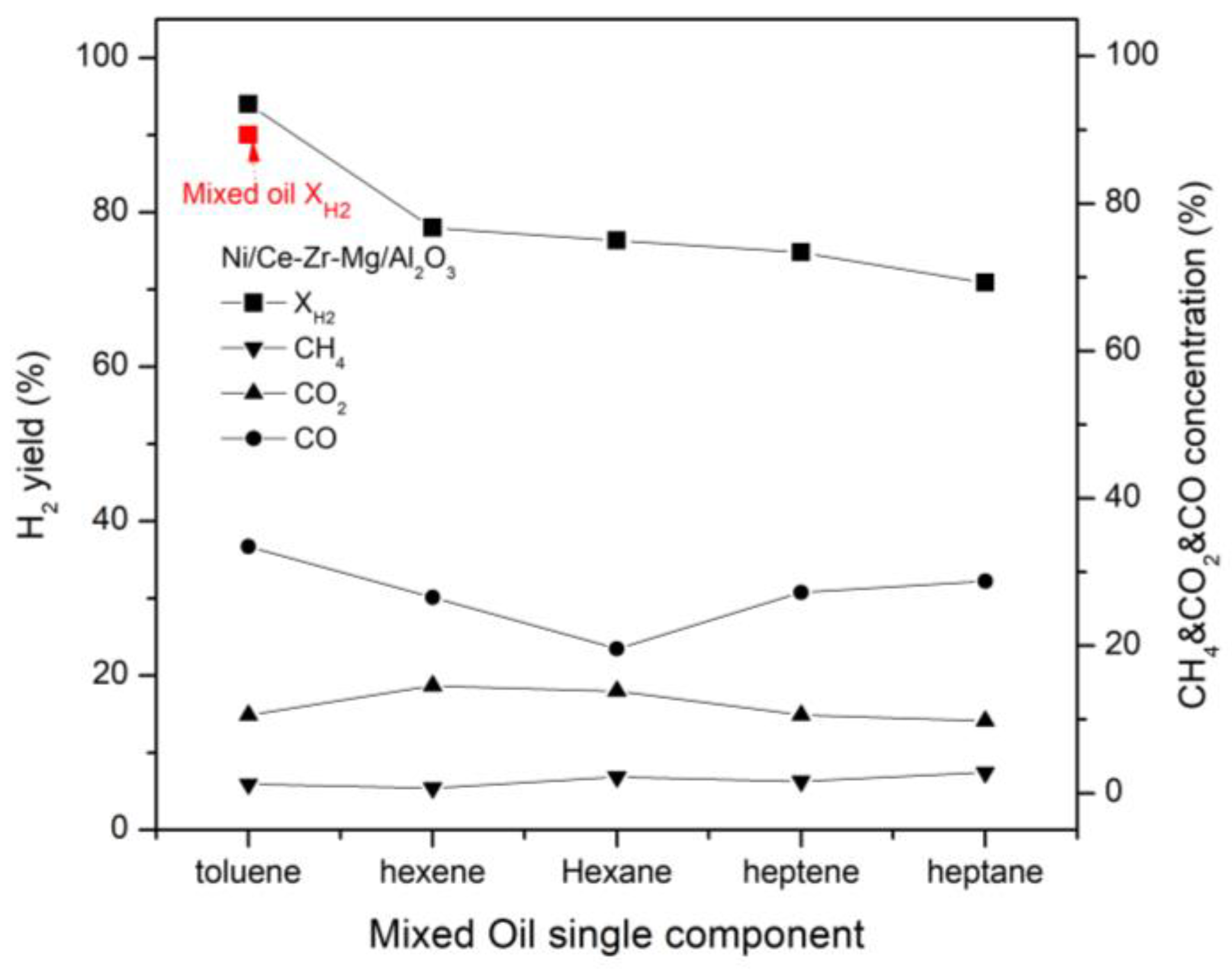
3.6. Effect of Single Components on Hydrogen Yield

Figure 10 shows the hydrogen yield for single components under a reaction temperature of 850 °C, S/C = 2, and a space velocity of 10,000 h−1. As shown in the figure, the hydrogen yield of toluene, an aromatic hydrocarbon, was about 95%, compared to the hydrogen yield of about 70–76% for aliphatic hydrocarbons. In addition, in the case of toluene steam reforming, the difference between the CO component and the CO2 component was higher than that of the aliphatic compound, which is considered to be due to the steam reforming reaction and the rWGS reaction by water. These results were consistent with the experimental results reported by Kontchouo et al. [13]. The hydrogen yield was the highest for the aromatic compound toluene, followed by hexene, hexane, heptane, and heptane. The hydrogen yields of the alkene compounds were higher than those of the alkane compounds, and increased as the number of carbon atoms increased.

3.7. The Durability and Activity Test of the Catalyst

Experimental results of the durability test of the catalyst 3 wt.% Ni/Ce-Zr-Mg/Al2O3 under a reaction temperature of 850 °C, S/C = 2 and a space velocity of 10,000 h−1 are illustrated in Figure 11. For approximately 100 h, a consistent activation was maintained at a hydrogen yield between 90–93% and carbon conversion rate between 93–95%. In addition, a stable activation and durability of the 3 wt% Ni/Ce-Zr-Mg/Al2O3 catalyst was observed.

4. Conclusions

In this study, we performed hydrogen production through the SR reaction of waste plastic pyrolysis oil over a 3 wt.% Ni/Ce-Zr-Mg/Al2O3 catalyst. The results were as follows:
Hydrogen yield increased as reaction temperature increased from 750–850 °C. The hydrocarbon reforming reaction was highly endothermic and the reaction activation increased with increasing temperature.
Within the 7600–19,000 h−1 range, hydrogen yield was maintained at ~80% up to a space velocity of 13,000 h−1, but decreased thereafter to 70%. The optimal space velocity for producing hydrogen was 10,000–12,000 h−1.
Hydrogen yield increased as the S/C ratio increased from 0.6–4; at the same time, methane concentration and carbon deposition decreased. However, the optimal S/C ratio was ~2 because excessive water injection above this value absorbed significant heat and resulted in energy consumption.
The addition of oxygen increased the hydrogen yield by ~2%; at the same time, activation was maintained and the carbon deposited on the catalyst was removed via oxidation.
Constant activation was maintained during a 100 h durability test of the 3 wt.% Ni/Ce-Zr-Mg/Al2O3 catalyst performed at 850 °C for 10,000 h−1 with S/C = 2; the test produced a 90–93% hydrogen yield and carbon conversion rate of 93–95%. In summary, the catalyst had good durability.
In the future, we will determine the optimal conditions for model oil, and conduct experiments using actual waste plastic pyrolysis oil. Furthermore, we aim to conduct experiments by applying the findings from an active hydrogen production demonstration plant. We intend to apply these experimental findings to the construction of waste plastic production plants.

Author Contributions

Data curation: S.S. and H.J., visualization: S.S. and H.J., formal analysis: S.S.; investigation and writing—original draft: D.H.; writing—review and editing: Y.B. and D.H.; funding acquisition and resources: W.C.; validation: W.C. and Y.B.; conceptualization and supervision: Y.B. All authors have read and agreed to the published version of the manuscript.

Funding

This study was funded by the Korea Institute of Energy Technology Evaluation and Planning (KETEP) and the Korean Ministry of Trade, Industry and Energy (No. 20213030040270, Development and demonstration of hydrogen production process based on waste plastic non-oxidative pyrolysis). This work was supported by the Korea Institute of Planning and Evaluation for Technology in Food, Agriculture and Forestry (IPET) and Korea Smart Farm R&D Foundation (KosFarm) through the Smart Farm Innovation Technology Development Program, funded by the Ministry of Agriculture, Food and Rural Affairs (MAFRA) and Ministry of Science and ICT (MSIT) and Rural Development Administration (RDA)(421038-03).

Data Availability Statement

Not applicable.

Conflicts of Interest

The authors declare no conflict of interest.

References

  1. Jo, J.; Shin, D.; Kim, Y. Pyrolysis of Plastic Waste: Current Status and Policy Tasks; KEI Policy Report; Korea Environment Institute: Sejong, Republic of Korea, 2022. [Google Scholar]
  2. Kim, Y.; Lim, S.; Kim, J.; Jae, J. Recent Research Trend in the Catalytic Pyrolysis of Waste Plastics for the Production of Renewable Fuels and Chemicals. KIC News 2021, 24, 10–21. [Google Scholar]
  3. Shent, H.; Pugh, R.J.; Forssberg, E. A review of plastics waste recycling and the flotation of plastics. Resour. Conserv. Recycl. 1999, 25, 85–109. [Google Scholar] [CrossRef]
  4. Samsung Securities Co. Nature Climate Change; Report; Samsung Securities Co., Ltd.: Seoul, Republic of Korea, 2021. [Google Scholar]
  5. Agora Energiewende and Wuppertal Institute. Breakthrough Strategies for Climate-Neutral Industry in Europe: Policy and Technology Pathways for Raising EU Climate Ambition. 2021. Available online: https://www.agora-energiewende.de/en/publications/breakthrough-strategies-for-climate-neutralindustry-in-europe-study/ (accessed on 26 May 2021).
  6. Nabgan, W.; Nabgan, B.; Abdullah, T.A.T.; Ngadi, N.; Jalil, A.A.; Nordin, A.H.; Latif, N.A.F.A.; Othman, N.F.H. Hydrogen Production from Catalytic Polyethylene Terephthalate Waste Reforming Reaction, an overview. Catal. Sustain. Energy 2020, 7, 45–64. [Google Scholar] [CrossRef]
  7. Holladay, J.D.; Hu, J.; King, D.L.; Wang, Y. An overview of hydrogen production technologies. Catal. Today 2009, 139, 244–260. [Google Scholar] [CrossRef]
  8. Lavoie, J.M. Review on dry reforming of methane, a potentially more environmentally-friendly approach to the increasing natural gas exploitation. Front. Chem. 2014, 2, 81. [Google Scholar] [CrossRef] [PubMed] [Green Version]
  9. Sharifianjazi, F.; Esmaeilkhanian, A.; Bazli, L.; Eskandarinezhad, S.; Khaksar, S.; Shafiee, P.; Yusuf, M.; Abdullah, B.; Salahshour, P.; Sadeghi, F. A review on recent advances in dry reforming of methane over Ni- and Co-based nanocatalysts. Int. J. Hydrog. Energy 2022, 47, 42213–42233. [Google Scholar] [CrossRef]
  10. Pawelczyk, E.; Wysocka, I.; Ģebicki, J. Pyrolysis Combined with the Dry Reforming of Waste Plastics as a Potential Method for Resource Recovery—A Review of Process Parameters and Catalysts. Catalysts 2022, 12, 362. [Google Scholar] [CrossRef]
  11. Farooqi, A.S.; Yusuf, M.; Ishak, M.A.I.; Zabidi, N.A.M.; Saidur, R.; Khan, A. Combined H2O and CO2 Reforming of CH4 Over Ca Promoted Ni/Al2O3 Catalyst: Enhancement of Ni-CaO Interactions. In Advances in Material Science and Engineering; Springer: Berlin/Heidelberg, Germany, 2021; pp. 220–229. [Google Scholar]
  12. Bona, S.; Guillén, P.; Alcalde, J.G.; García, L.; Bilbao, R. Toluene steam reforming using coprecipitated Ni/Al catalysts modified with lanthanum or cobalt. Chem. Eng. J. 2008, 137, 587–597. [Google Scholar] [CrossRef]
  13. Kontchouo, F.M.B.; Gao, Z.; Xianglin, X.; Wang, Y.; Sun, Y.; Zhang, S.; Hu, X. Steam reforming of n-hexane and toluene: Understanding impacts of structural difference of aliphatic and aromatic hydrocarbons on their coking behaviours. J. Environ. Chem. Eng. 2021, 9, 106383. [Google Scholar] [CrossRef]
  14. Rostrupnielsen, J.R.; Hansen, J.H.B. CO2 reforming of methane over transition metals. J. Catal. 1993, 144, 38–49. [Google Scholar] [CrossRef]
  15. Freni, S.; Cavallaro, S.; Mondello, N.; Spadaro, L.; Frusteri, F. Production of hydrogen for MC fuel cell by steam reforming of ethanol over MgO supported Ni and Co catalysts. Catal. Commun. 2003, 4, 259–268. [Google Scholar] [CrossRef]
  16. Tuza, P.V.; Manfro, R.L.; Ribeiro, N.F.; Souza, M.M. Production of renewable hydrogen by aqueous-phase reforming of glycerol over Ni–Cu catalysts derived from hydrotalcite precursors. Renew. Energy 2013, 50, 408–414. [Google Scholar] [CrossRef]
  17. García-Diéguez, M.; Pieta, I.S.; Herrera, M.C.; Larrubia, M.A.; Alemany, L.J. Nanostructured Pt- and Ni-based catalysts for CO2-reforming of methane. J. Catal. 2010, 270, 136–145. [Google Scholar] [CrossRef]
  18. Davda, R.; Shabaker, J.; Huber, G.; Cortright, R.; Dumesic, J.A. A review of catalytic issues and process conditions for renewable hydrogen and alkanes by aqueous-phase reforming of oxygenated hydrocarbons over supported metal catalysts. Appl. Catal. B Environ. 2005, 56, 171–186. [Google Scholar] [CrossRef]
  19. Ross, J.R.H. Heterogeneous Catalysis: Fundamentals and Applications. Angew. Chem. 2012, 51, 5289. [Google Scholar] [CrossRef]
  20. Abdullah, T.A.T.; Nabgan, W.; Kamaruddin, M.J.; Mat, R.; Johari, A.; Ahmad, A. Hydrogen production from acetic acid steam reforming over bimetallic Ni-Co on La2O3 catalyst—Effect of the catalyst dilution. Appl. Mech. Mat. 2014, 493, 39–44. [Google Scholar] [CrossRef]
  21. Akbari, E.; Mehdi, S.; Rezea, A.M. CeO2 promoted Ni-MgO-Al2O3 nanocatalysts for carbon dioxide reforming of methane. J. CO2 Util. 2018, 24, 128–138. [Google Scholar] [CrossRef]
  22. Ray, K.; Bhardwaj, R.; Singh, B.; Deo, G. Developing descriptors for CO2 methanation and CO2 reforming of CH4 over Al2O3 supported Ni and low-cost Ni based alloy catalysts. Phys. Chem. Chem. Phys. 2018, 20, 15939–15950. [Google Scholar] [CrossRef]
  23. Bacariza, M.C.; Graca, I.; Bebiano, S.S.; Lopes, J.M.; Henriques, C. Micro-and mesoporous supports for CO2 methanation catalysts: A comparison between SBA-15, MCM-41 and USY zeolite. Chem. Eng. Sci. 2018, 175, 72–83. [Google Scholar] [CrossRef] [Green Version]
  24. Liu, W.; Li, L.; Zhang, X.; Wang, Z.; Wang, X.; Peng, H. Design of Ni-ZrO2-SiO2 catalysts with ultra-high sintering and coking resistance for dry reforming of methane to prepare syngas. J. CO2 Util. 2018, 27, 297–307. [Google Scholar] [CrossRef]
  25. Li, H.; Wang, J. Study on CO2 reforming of methane to syngas over Al2O3-ZrO2 supported Ni catalysts prepared via a direct sol-gel process. J. Chem. Eng. Sci. 2004, 59, 4861–4867. [Google Scholar] [CrossRef]
  26. Löfberg, A.; Guerrero-Caballero, J.; Kane, T.; Rubbens, A.; Jalowiecki-Duhamel, L. Ni/CeO2 based catalysts as oxygen vectors for the chemical looping dry reforming of methane for syngas production. Appl. Catal. B Environ. 2017, 212, 159–174. [Google Scholar] [CrossRef]
  27. Yan, X.; Hu, T.; Liu, P.; Li, S.; Zhao, A.; Zhang, Q.; Jiao, W.; Chen, S.; Wang, P.; Lu, J.; et al. Highly efficient and stable Ni/CeO2-SiO2 catalyst for dry reforming of methane: Effect of interfacial structure of Ni/CeO2 on SiO2. Appl. Catal. B Environ. 2019, 246, 221–231. [Google Scholar] [CrossRef]
  28. Sengupta, S.; Deo, G. Modifying alumina with CaO or MgO in supported Ni and Ni-Co catalysts and its effect on dry reforming of CH4. J. CO2 Util. 2015, 10, 62–77. [Google Scholar] [CrossRef]
  29. Al-Fatesh, A.S.; Arafat, Y.; Atia, H.; Ibrahim, A.; Luu, Q.; Ha, M.; Schneuder, M.; M-Pohl, M.; Fakeeha, A.H. CO2 reforming of methane to produce syngas over Co-Ni/SBA-15-Catalysts: Effect of support modifiers (Mg, La and Sc) on catalytic stability. J. CO2 Util. 2017, 21, 395–404. [Google Scholar] [CrossRef]
  30. Feng, X.; Feng, J.; Li, W. Insight into MgO promoter with low concentration for the carbon deposition resistance of Ni-based catalysts in the CO2 reforming of CH4. Chin. J. Catal. 2018, 39, 88–98. [Google Scholar] [CrossRef]
  31. Hu, D.; Liu, C.; Li, L.; Lv, K.L.; Zhang, Y.H.; Li, J.L. Carbon dioxide reforming of methane over nickel catalysts supported on TiO2(001) nanosheets. Int. J. Hydrog. Energy 2018, 43, 21345–21354. [Google Scholar] [CrossRef]
  32. Ahmed, S.; Aitani, A.; Rahman, F.; Al-Dawood, A.; Al-Muhaish, F. Decomposition of hydrocarbons to hydrogen and carbon. Appl. Catal. A 2009, 359, 1–24. [Google Scholar] [CrossRef]
  33. Wang, L.; Li, D.; Koike, M.; Watanabe, H.; Xu, Y.; Nakagawa, Y.; Tomishige, K. Catalytic performance and characterization of Ni-Co catalysts for the steam reforming of biomass tar to synthesis gas. Fuel 2013, 112, 654–661. [Google Scholar] [CrossRef]
  34. Wang, L.; Li, D.; Koike, M.; Koso, S.; Nakagawa, Y.; Xu, Y.; Tomishige, K. Catalytic performance and characterization of Ni-Fe catalysts for the steam reforming of tar from biomass pyrolysis to synthesis gas. Appl. Catal. A 2011, 392, 248–255. [Google Scholar] [CrossRef]
  35. Chen, J.; Tamura, M.; Nakagawa, Y.; Okumura, K.; Tomishige, K. Promoting effect of trace Pd on hydrotalcite-derived Ni/Mg/Al catalyst in oxidative steam reforming of biomass tar. Appl. Catal. B 2015, 179, 412–421. [Google Scholar] [CrossRef]
  36. Guan, G.; Chen, G.; Kasai, Y.; Lim, E.W.C.; Hao, X.; Kaewpanha, M.; Abuliti, A.; Fushimi, C.; Tsutsumi, A. Catalytic steam reforming of biomass tar over iron- or nickel-based catalyst supported on calcined scallop shell. Appl. Catal. B 2012, 115–116, 159–168. [Google Scholar] [CrossRef]
  37. Achouri, I.E.; Abatzoglou, N.; Fauteux-Lefebvre, C.; Braidy, N. Diesel steam reforming: Comparison of two nickel aluminate catalysts prepared by wet-impregnation and co-precipitation. Catal. Today 2013, 207, 13–20. [Google Scholar] [CrossRef]
  38. Han, D.; Kim, Y.; Cho, W.; Baek, Y. Effect of Oxidants on Syngas Synthesis from Biogas over 3 wt % Ni-Ce-MgO-ZrO2/Al2O3. Catal. Energ. 2020, 13, 297. [Google Scholar]
  39. Li, H.; Ren, J.; Qin, X.; Qin, Z.; Lin, J.; Li, Z. Ni/SBA-15 catalysts for CO methanation: Effects of V, Ce, and Zr promoters. RSC Adv. 2015, 115, 96504–96517. [Google Scholar] [CrossRef]
  40. Tao, M.; Meng, X.; Lv, Y.; Bian, Z.; Xin, Z. Effect of impregnation solvent on Ni dispersion and catalytic properties of Ni/SBA-15 for CO methanation reaction. Fuel 2016, 130, 289–297. [Google Scholar] [CrossRef]
  41. Yusuf, M.; Farooqi, A.; Ying, Y.; Alam, M.; Hellgardt, K.; Abdullah, B. Syngas production employing nickel on aluminamagnesia supported catalyst via dry methane reforming. Materialwiss. Werkstoftech 2021, 52, 10901100. [Google Scholar] [CrossRef]
  42. Pan, Y.; Wang, Z.X.; Kan, T.; Zhu, X.F.; Li, Q.X. Hydrogen production by catalytic steam reforming of bio-oil, naphtha and CH4 over C12A7-Mg catalyst. Chin. J. Chem. Phys. 2006, 19, 190. [Google Scholar] [CrossRef]
  43. Kong, M.; Yang, Q.; Fei, J.; Zheng, X. Experimental study of Ni/MgO catalyst in carbon dioxide reforming of toluene, a model compound of tar from biomass gasification. Int. J. Hydrog. Energy 2012, 37, 13355–13364. [Google Scholar] [CrossRef]
  44. Yoon, S.J.; Choi, Y.C.; Lee, J.G. Hydrogen production from biomass tar by catalytic steam reforming. Energy Convers Manag. 2010, 51, 42–47. [Google Scholar] [CrossRef]
  45. Phongprueksathat, N.; Meeyoo, V.; Rirksomboon, T. Steam reforming of acetic acid for hydrogenproduction: Catalytic performances of Ni and Co supported on Ce0.75Zr0.25O2 catalysts. Int. J. Hydrog. Energy 2019, 44, 9359–9367. [Google Scholar] [CrossRef]
  46. Świerczyński, D.; Libs, S.; Courson, C.; Kiennemann, A. Steam reforming of tar from a biomass gasification process over Ni/olivine catalyst using toluene as a model compound. Appl. Catal. B Environ. 2007, 74, 211–222. [Google Scholar] [CrossRef]
  47. Gao, N.; Liu, S.; Han, Y.; Xing, C.; Li, A. Steam reforming of biomass tar for hydrogen production over NiO/ceramic foam catalyst. Int. J. Hydrog. Energy 2015, 40, 7983–7990. [Google Scholar] [CrossRef]
  48. Gao, N.; Wang, X.; Li, A.; Wu, C.; Yin, Z. Hydrogen production from catalytic steam reforming of benzene as tar model compound of biomass gasification. Fuel Process. Technol. 2016, 148, 380–387. [Google Scholar] [CrossRef]
Figure 1. Block diagram detailing the synthesis process of 3 wt.% Ni catalyst for steam reforming of pyrolysis oil [38].
Energies 16 02656 g001
Figure 2. Schematic diagram of the pyrolysis oil reforming reactor.
Energies 16 02656 g002
Figure 3. SEM images of (a) Fresh and (b) Spent 3 wt.% Ni/Ce-Zr-Mg/Al2O3 catalysts.
Energies 16 02656 g003
Figure 4. X-ray diffraction patterns of (a) Fresh and (b) Spent 3 wt.% Ni/Ce-Mg-Zr/Al2O3 catalyst.
Energies 16 02656 g004
Figure 5. XPS patterns of the (a) Fresh and (b) Spent 3 wt.% Ni/Ce-Mg-Zr/Al2O3 catalyst.
Energies 16 02656 g005
Figure 6. TGA analysis under atmosphere for the 3 wt.% Ni/Ce-Mg-Zr/Al2O3 catalyst.
Energies 16 02656 g006
Figure 7. Effect of reaction temperature on hydrogen yield (S/C = 2, GHSV = 10,000h-1).
Energies 16 02656 g007
Figure 8. Effect of GHSV on H2 yield and CH4 concentration during the waste plastic pyrolysis oil reforming reaction.(temp.=850 °C, S/C = 2).
Energies 16 02656 g008
Figure 9. Hydrogen yield according to the S/C ratio. (temp.= 850 °C, GHSV=10,000h-1).
Energies 16 02656 g009
Figure 10. Effect of single components on hydrogen yield.(temp.= 850 °C, S/C = 2, GHSV = 10,000 h-1).
Energies 16 02656 g010
Figure 11. The durability and activity test of the catalyst for 100 h. (temp.= 850 °C, S/C = 2, GHSV = 10,000 h-1).
Energies 16 02656 g011
Table 1. Mixed model oil concentration.
Boiling Point (°C)Concentration of
Pyrolysis Oil (%)
Mixed Ratio of
Model Oil (%)
1-Hexene63.41.5511
N-Hexane68.71.8412
1-Heptene93.62.7717
N-Heptane98.52.1712
Toluene110.66.1348
Table 2. Experiment conditions.
Temperature (°C)750, 800, 850
Pressure (atm)1
GHSV (h−1)7600, 10,000, 15,000, 19,100
S/C ratio0.6, 2, 3, 4
Table 3. Specific surface area of the 3 wt.% Ni/Ce-Zr-Mg/Al2O3 catalyst.
BET Surface Area (m2/g)Pore Volume
(cm3/g)
Pore Size
(Å)
Fresh catalyst2.940.00172647.31 Å
Spent catalyst5.010.00732756.45 Å
Table 4. Composition of the 3 wt% Ni/Ce-ZrO2/Al2O3 catalyst before and after reforming.
MetalNiOCeMgOZrC *
Fresh (%)3.11.33.12.60
Spent (%)2.71.12.72.45.8
*: Measurement data by SEM energy-dispersive spectroscopy (EDAX).
Table 5. Effect of O2 and N2 addition on H2 yield.
S/CGHSV (h-1)Reaction Material (mL/min)H2 Yield (%)
OilH2OO2N2
210,0000.0580.11301281.1
12094.6
0090.1
Disclaimer/Publisher’s Note: The statements, opinions and data contained in all publications are solely those of the individual author(s) and contributor(s) and not of MDPI and/or the editor(s). MDPI and/or the editor(s) disclaim responsibility for any injury to people or property resulting from any ideas, methods, instructions or products referred to in the content.

