Article

First-Order Linear Active Disturbance Rejection Control for Turbofan Engines

1
School of Aerospace Engineering, Xiamen University, Xiamen 361102, China
2
Huawei Technologies France SASU, Xiamen 361102, China
*
Author to whom correspondence should be addressed.
Energies 2023, 16(6), 2743; https://doi.org/10.3390/en16062743
Submission received: 3 February 2023 / Revised: 4 March 2023 / Accepted: 9 March 2023 / Published: 15 March 2023
(This article belongs to the Special Issue Recent Advances in Thermofluids, Combustion and Energy Systems)

Abstract

:
Proportional-integral (PI) control is widely used in turbofan-engine control, while first-order linear active disturbance rejection control (FOLADRC) is a possible approach to update it. This paper investigates FOLADRC. In methodology, it proposes a new block diagram of FOLADRC, which shows that FOLADRC can be viewed as a PI controller, a low-pass feedback filter, and a pre-filter. The low-pass filter helps to reject high-frequency measurement noise, while the pre-filter can attenuate overshoot in step response. In simulation, 14 published linearized model matrices of NASA’s CMAPSS-1 90k engine model are used to verify the above theory. Simulations show one FOLADRC controller can be simultaneously used for the 14 linear models and guarantee that all the 14 low-pressure turbine speed control loops have enough phase margin and no overshoot. Thus, replacing several PI controllers with one FOLADRC controller is possible, and FOLADRC can be used to simplify the control system design of turbofan engines.

1. Introduction

Turbofan engines are widely used in military and civil aircrafts. They have the advantages of large thrust, high propulsion efficiency, low fuel consumption, and long flight distance. To achieve the above advantages and obtain extreme performance, engines must be operated with feedback control. Thus, feedback control is an important issue of today’s turbofan-engine technology. Control approaches such as PI or PID control, LQR,  H , gain scheduling, and sliding model control have been applied to control turbofan engines [1,2]. In the above approaches, PI control is the simplest one. It is mature, reliable, familiar to engineers, and widely used in turbofan-engine control [3], especially in China [4].
For turbofan engines, PI control is usually used in an adaptive control framework. It sets a number of flight conditions of the engine, which is defined by the inlet conditions and desired thrust. Then, for each flight condition, a PI controller is designed to guarantee the engine performs well if it is near the flight condition. When the engine works, an adaptive control algorithm monitors the engine, selects the correct PI controller based on the current status of the engine, and switches/tunes the controller if necessary. In this way, PI control can guarantee that the engine has good performance in the whole flight envelope.
However, to obtain such an adaptive PI control is a time-consuming work. The flight conditions must be carefully selected so that they can cover the whole flight envelope while their number is not large. Much attention must be paid to design and test the adaptive control algorithm, especially its stability analysis, because its stability cannot be guaranteed only by the stability of every flight condition and PI controller pair. Thus, if there exists a PI-like control approach that can deal with several flight conditions and even the whole flight envelope, it will significantly simplify the design of turbofan control systems to save much time and money.
FOLADRC is a possible candidate for such PI-like control. It is the simplest ADRC, while ADRC is a general control technology proposed by Han [5,6]. Han established ADRC with the motivation to improve PID control. ADRC has its philosophy and terminology. It views the plant as an integrator chain disturbed by total disturbance, which means the total effect of external disturbance, model uncertainty, and measurement noise. ADRC establishes ESO to estimate the total disturbance and cancel it with feedback control. In this way, ADRC can obtain good performance for a large class of plants by tuning parameters. In the past two decades, ADRC has received much attention from the control community and industry. Its detailed survey can be found in [7,8,9].
The initial ADRC is nonlinear and has more than 10 parameters to tune. Gao simplified it to LADRC, in which the ESO and feedback are linear [10]. For LADRC, its order is how many integrators in the integrator chain. It is the most important parameter and determines the structure of the LADRC, as well as the number of parameters to tune. For example, FOLADRC has a first-order state feedback and a second-order ESO, as well as four parameters to tune; while SOLADRC has a second-order state feedback, a third-order ESO, and six parameters to tune.
Both FOLADRC and SOLADRC are applied widely. Recently, FOLADRC plays a more and more important role in process control [11,12,13,14,15,16,17,18], and a transition from PI/PID control to ADRC is thought taking place in thermal power plants [19]. At the same time, theory research reveals the relationship between FOLADRC/SOLADRC and PI/PID control: FOLADRC and SOLADRC can be respectively viewed as PI and PID control with filters [20,21,22,23]. Furthermore, it is proved that if a plant can be controlled by PI control, then it can be controlled by FOLADRC [21]. Thus, to replace PI control with FOLADRC and obtain better performance may be feasible.
This paper investigates using FOLADRC to replace PI control in turbofan control, especially using one FOLADRC controller to replace several PI controllers. Similar research has been reported in [3], where SOLADRC was used in NASA’s MAPSS package to replace multivariable PI control. It focused on the decoupling ability of LADRC and simulations, while lacking rigorous theoretical analysis because the theory had not been developed. Compared with [3], the contributions of this paper are mainly in methodology. It analyzes the structure of FOLADRC and provides a new block diagram, which shows that FOLADRC can be viewed as a PI controller, a feedback low-pass filter, and a pre-filter. Then, with Bode plots, it illustrates that FOLADRC is better in attenuating overshoot and rejecting measurement noise than PI control. These are the reasons to replace PI control with FOLADRC. Then, simulations studies are carried out based on the data of NASA’s CMAPSS-1 package [24]. With its 14 flight conditions’ linear models published in [2], a FOLADRC controller is designed to control the 14 models’ incremental fan speed with incremental fuel flow rate. Simulations illustrate that with the FOLADRC controller, all the 14 control loops have enough PM and good transient performance. That is, replacing several PI controllers with one FOLADRC controller is feasible.

2. Methodology

In this paper, all signals are assumed to have Laplace transforms. Lowercase letters are used to denote time-domain signals, for example,  x ( t ) . Corresponding uppercase letters are used to denote the signals’ Laplace transforms. For example:
X ( s ) = ( x ( t ) ) 0 x ( t ) e s t d x

2.1. Continuous-Time FOLADRC

Now we introduce continuous-time FOLADRC. Suppose we have a single-input–single-output (SISO) plant, shown in Figure 1. The plant has a transfer function  P ( s ) . Its input is a control signal  u  added by a disturbance  d , while the output  y  is measured and measurement noise  n  is added to the measurement output  y m . That is, we have:
Y ( s ) U ( s ) + D ( s ) = P ( s )
and
y m = y ( t ) + n ( t )
FOLADRC views the plant (1)–(2) as a disturbed integrator:
y ˙ m = b 0 u + f
where the parameter  b 0  is positive. The term  f  is called total disturbance. It is all the uncertain dynamics that make the plant (3) different with:
y ˙ m = b 0 u
It includes the external disturbance  d , the effect of measurement noise  n , and the plant’s uncertain dynamics, which is called internal disturbance in ADRC theory. Note that here we only assume the plant is SISO and has transfer function  P ( s ) . Different with some existing literature, we do not provide an assumption on the plant’s order, stability, and if it has zeros. This is a data-driven perspective. The problem is to design an output feedback control to track a reference signal  r , which typically is a step.
Introducing state variable  x 1 = y  and extended state  x 2 = f , Equations (1) and (2) can be re-written in state space as:
{ x ˙ 1 = x 2 + b 0 u , x ˙ 2 = f ˙ ,
y m = x 1
To estimate  x 1  and  x 2 , a linear ESO for (5)–(6) is designed as:
{ x ^ ˙ 1 = β 1 ( y m x ^ 1 ) + x ^ 2 + b 0 u , x ^ ˙ 2 = β 2 ( y m x ^ 1 ) ,
where  x ^ 1  and  x ^ 2  are respectively the estimations of  x 1  and  x 2 , while  β 1  and  β 2  are tuning parameters. Let  l 1  be a tuning parameter and the controller be:
u = 1 b 0 [ l 1 ( r x ^ 1 ) x ^ 2 ]
The linear ESO (7) and the controller (8) are the FOLADRC, we call it as first-order because (4) is an integrator with order one.

2.2. Transfer Functions and Block Diagram

Substituting (8) into (7), we have:
{ x ^ ˙ 1 = ( β 1 + l 1 ) x ^ 1 + β 1 y m + l 1 r , x ^ ˙ 2 = β 2 x ^ 1 + β 2 y m .
Then viewing (8) as the output of (9), with  y m  and  r  as two inputs, we obtain the transfer functions from  y m  and  r  respectively to  u  as:
U ( s ) Y m ( s ) = ( β 1 l 1 + β 2 ) s + β 2 l 1 b 0 s ( s + β 1 + l 1 )
U ( s ) R ( s ) = l 1 ( s 2 + β 1 s + β 2 ) b 0 s ( s + β 1 + l 1 )
Let
C ( s ) = ( β 1 l 1 + β 2 ) s + β 2 l 1 b 0 s ( s + β 1 + l 1 )
C 1 ( s ) = l 1 ( s 2 + β 1 s + β 2 ) ( β 1 l 1 + β 2 ) s + β 2 l 1
and the FOLADRC system has the block diagram in Figure 2a. Then define:
K P = l 1 β 1 + β 2 b 0 ( l 1 + β 1 )
K I = l 1 β 2 b 0 ( l 1 + β 1 )
C P I ( s ) = K P + K I 1 s
F L ( s ) = l 1 + β 1 s + l 1 + β 1
F P ( s ) = C 1 ( s ) F L ( s )
With (12)–(16), Figure 2a can be re-drawn as Figure 2b.
Figure 2. The blocks of FOLADRC (a,b).
Energies 16 02743 g002
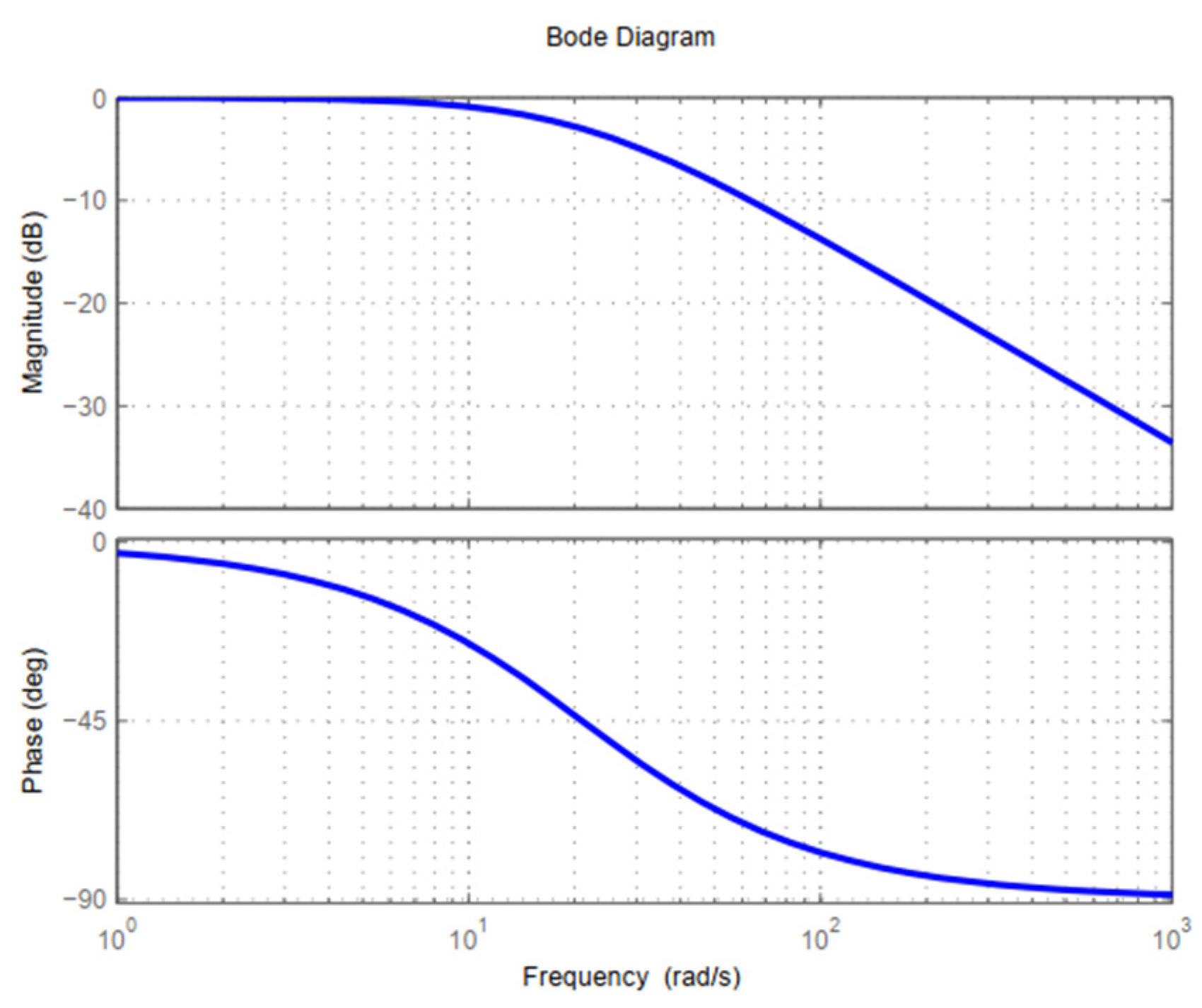
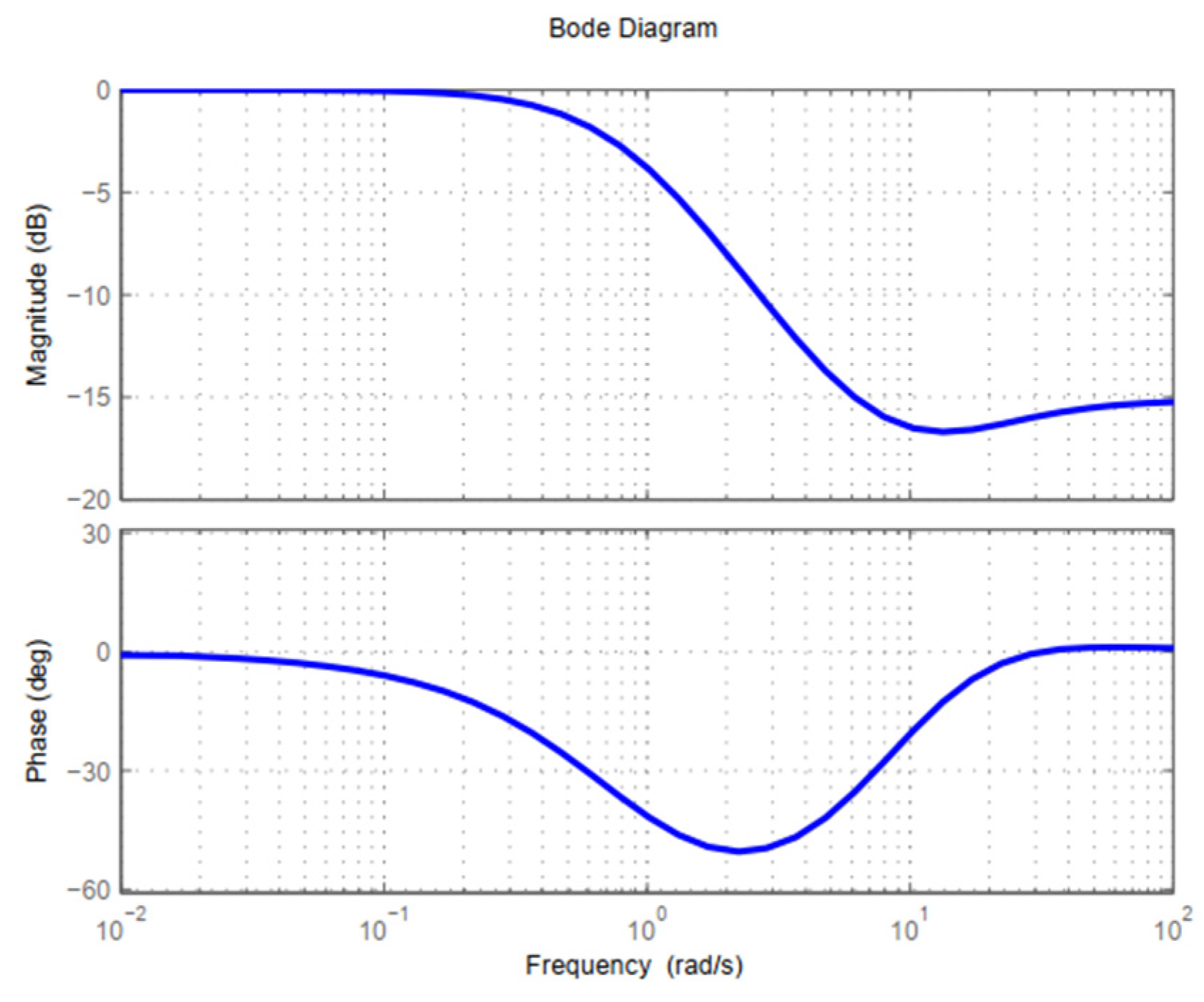
Figure 2b is the new block diagram provided by this paper. It illustrates the relationship between FOLADRC and PI control. The core of FOLADRC is a PI control (14). Compared with the unity PI feedback control in Figure 3, FOLADRC has two blocks more. One is the feedback low-pass filter  F L ( s ) , whose typical Bode diagram is shown in Figure 4. The other is the pre-filter  F P ( s ) , whose typical Bode diagram is shown in Figure 5. The Bode diagram is a basic approach in control theory. Its details can be found in control textbooks, for example, [25].

2.3. Comparison between FOLADRC and PI Control

Compared with PI control, FOLADRC has the following three properties:
  • (C1) FOLADRC can control the plants controlled by the PI controller.
  • (C2) Pre-filter  F P ( s )  can attenuate the overshoot.
  • (C3) Low-pass filter  F L ( s )  is helpful to reject the high-frequency measurement noise.
C1 has been rigorously proved in [21]. Now we illustrate C2 with a Bode diagram.
Suppose the unit feedback loop in Figure 3 has an overshoot. In frequency-domain, this means its closed-loop transfer function
W P I ( s ) = C P I ( s ) P ( s ) 1 + C P I ( s ) P ( s )
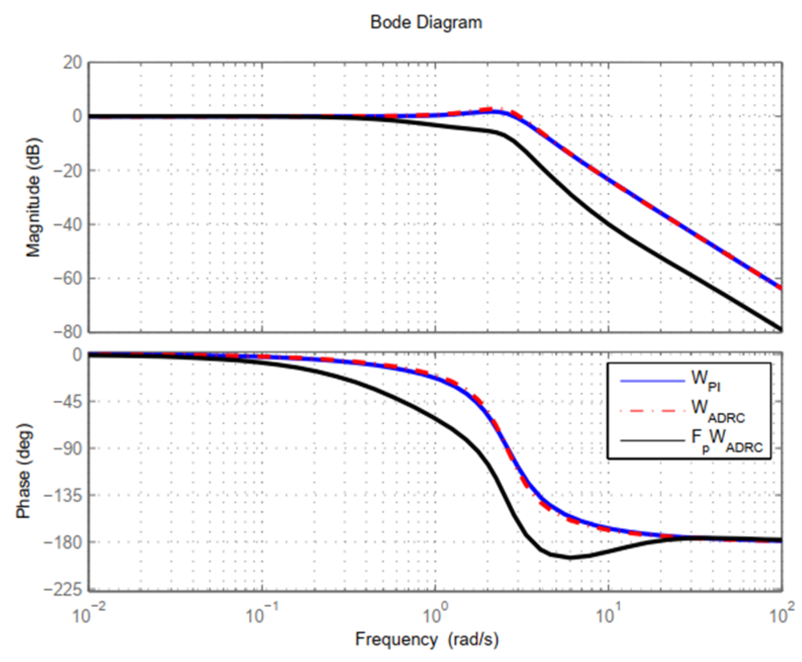
has a peak in its magnitude-frequency plot. A typical Bode diagram of  W P I ( s )  is drawn in Figure 6 with a blue line.
For the FOLADRC block diagram in Figure 2b, its closed-loop made of  C P I ( s ) P ( s ) , and  F L ( s )  has transfer function:
W A D R C ( s ) = C P I ( s ) P ( s ) 1 + C P I ( s ) P ( s ) F L ( s )
Since  F L ( s )  is a low-pass filter,  W A D R C ( s )  has a similar Bode diagram with  W P I ( s )  in low-frequency. A typical Bode diagram of  W A D R C ( s )  is drawn in Figure 6 with a red dash–dot line. It also has a peak in the magnitude-frequency plot.
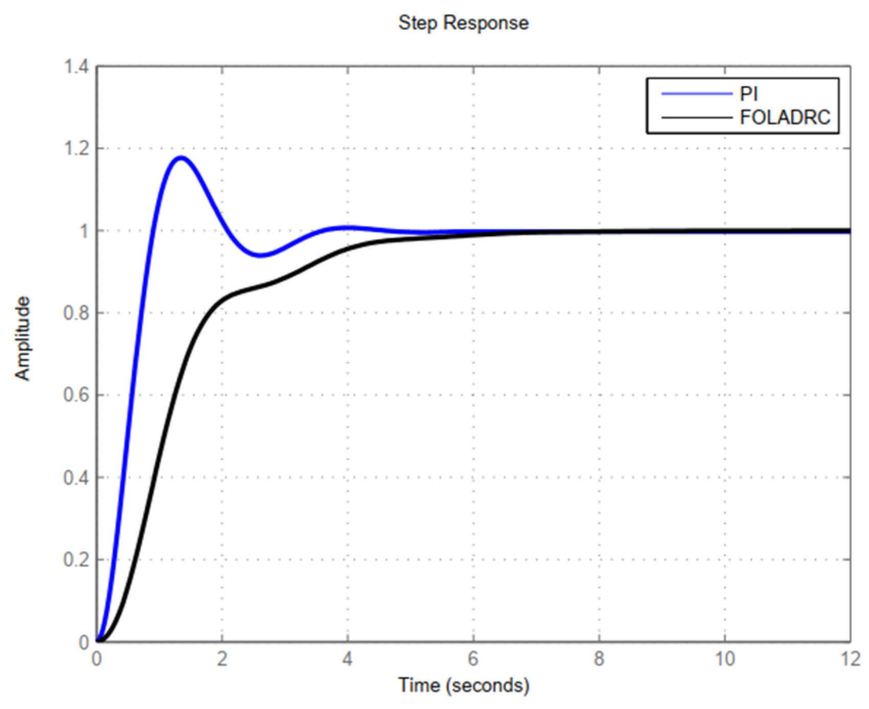
Recall the Bode diagram of  F P ( s )  in Figure 5 and note its magnitude-frequency plot. It has unity gain at DC. As the frequency increases, its gain decreases, then maintains a constant in high frequency. Thus,  F P ( s )  is helpful to attenuate the peak of  W A D R C ( s ) . A typical Bode diagram of  F P ( s ) W A D R C ( s )  is drawn in Figure 6 with black line. Because of  F P ( s ) F P ( s ) W A D R C ( s )  does not have a peak. In time-domain, this means FOLADRC does not have overshoot in its step response. Typical step responses of the FOLADRC and PI control are drawn in Figure 7.
For C3, we consider the transfer function from  n  to  y . In Figure 3, it is:
H P I ( s ) = Y ( s ) N ( s ) = C P I ( s ) P ( s ) 1 + C P I ( s ) P ( s )
Since  n  is a high-frequency signal, in its frequency band we have:
| C P I ( s ) P ( s ) | 1
Thus,
H P I ( s ) C P I ( s ) P ( s )
Similarly, for FOLADRC in Figure 2b, we have:
H A D R C ( s ) = Y ( s ) N ( s ) C P I ( s ) P ( s ) F L ( s )
Because  F L ( s )  is a low-pass filter, we conclude in the frequency band of  n ,
| H A D R C ( s ) | | H P I ( s ) |
That is why  F L ( s )  is helpful to reject the high-frequency measurement noise.
C1–C3 are the main theory results of this paper. With C1, an existing PI control can be replaced by a FOLADRC. With C2 and C3, it is natural to expect FOLADRC having better performance than PI control. Furthermore, C2 implies in controller switching systems with the time-varying plant, one FOLADRC controller may simultaneously replace several PI controllers.
Time-varying plants are not easy to control. To control them, a promising approach is multiple model adaptive control. This approach establishes a set of nominal models of the plant and guarantees that at each time, there exists at least one nominal model that can describe the plant with sufficient precision. Then, it designs a controller for each nominal model, and an adaptive control algorithm called supervisor to switch the controllers. The supervisor monitors the plant and compares it with the current nominal model. If the current model can precisely describe the plant, the model’s controller is online. If the plant changes so that the current model cannot precisely describe it, the supervisor switches its controller offline, selects a new model to precisely describe the plant, and switches the new model’s controller online. In this way, the plant can be robustly controlled and have satisfying performance.
The controllers are usually designed for a nominal model with specification such as gain crossover frequency, PM, and overshoot. For a unity feedback PI controller, to meet overshoot specification for several nominal models is difficult. But with C2, a FOLADRC controller may make it possible to have small overshoot for several nominal models. Thus, to take the place of several PI controllers with one FOLADRC controller is possible. An example of a controlling turbofan engine is shown in the next section.

2.4. Parameters Tuning

FOLADRC has four parameters to tune:  b 0 l 1 β 1 β 2 . Suggested by [10], in this paper we introduce a parameter called an observer bandwidth, denote it as  ω o , and let
β 1 = 2 ω o ,
β 2 = ω o 2 .
Thus, the number of tuning parameters is three. They can be tuned directly or indirectly.
Direct tuning is usually used when PM and gain crossover frequency  ω γ  are specified. It has a tuning parameter  α 1  and
l 1 = ω γ / α , β 1 = 2 α ω γ , β 2 = α 2 ω 2
By increasing  α , it can guarantee  C ( s ) P ( s )  has phase  ( 180 + P M ) . Then, tuning  b 0  to let  ω γ  will indeed be the gain crossover frequency.
Indirect tuning is usually based on an existing PI controller. Suppose the controller has transfer function (14), where  K P  and  K I  are known. Then let  ω o  be a tuning parameter and generate  b 0 , l 1 , β 1 , β 2  with Equations (12), (13), (17) and (18). By increasing  ω o , indirect tuning can find a FOLADRC controller whose  C ( s )  has a frequency response approximating that of (14) in low frequency. The details of indirect tuning can be found in [21].

3. Fan Speed Control Simulations

3.1. Models and Parameters

In this section, we show that one FOLADRC controller indeed can replace several PI controllers in controlling a turbofan engine’s fan speed. The engine’s model comes from the CMAPSS-1 package, which was developed by the NASA Glenn Research Center. CMAPSS-1 simulates a GE90-like turbofan engine with a dual-spool configuration, a bypass ratio of approximately 8.4, and 90,000-lb thrust. CMAPSS-1 is implemented in the MATLAB/Simulink environment, has a user-friendly graphical user interface (GUI), and can be used to evaluate the engine control approaches. Details of CMAPSS-1 can be found in [24]. Here, we only use its 14 representative linearized model matrices published in [2]. The model matrices are indexed by flight conditions that number from FC01 to FC14. Only six of the flight conditions, FC01, FC05, FC06, FC07, FC08, and FC09, are provided in Table 2.3 of [2], and we copy them in Table A1 of this paper’s Appendix A.
The 14 linearized model matrices come from the engine’s two-spool shaft nonlinear dynamic equations:
N ˙ f = f 1 ( N f , N c , u , w ) ,
N ˙ c = f 2 ( N f , N c , u , w ) ,
where  f 1  and  f 2  are respectively the net torques delivered by the LPT and HPT, while  u  and  w  are respectively the input and disturbance vectors. For all the 14 flight conditions, the Equations (19) and (20) are linearized and the matrices are published in Appendix B of [2]. With these matrices, the fan-speed control problem can be formulated as a SISO control problem with input  Δ W F  and output  Δ N f . In state space, the 14 equations are:
x ˙ = A i x + B i u ,
y = C i x ,
where  i = 1 , 2 , , 14  is the index, the state vector
x = [ Δ N f Δ N c ] ,
the control
u = Δ W F ,
and the output
y = Δ N f .
The matrix  A i  and  B i  can be found in Appendix B of [2]. Because of (21),
C i = [ 1 , 0 ] , i = 1 , 2 , , 14 .
All  A i B i , and  C i  are listed in Table A2 of this paper’s Appendix A. The transfer functions are calculated with
P i ( s ) = C i ( s I A i ) 1 B i ,
and also listed in Table A2.

3.2. Bode Diagrams, Stability, and Phase Margins

Now we try to find a FOLADRC and compare it with PI control
C P I ( s ) = 0.016 ( 1 + 3.70 1 s ) ,
which is designed in Section 3.1.5 of [2] based on FC01. After tuning, we obtain FOLADRC (7)–(8) with parameters
b 0 = 500 , l 1 = 1.767 , β 1 = 31.80 , β 2 = 252.8 .
Calculating with (10)–(11), we have transfer functions
C ( s ) = 1.767 ( 309 s + 446.6 ) 500 s ( s + 33.57 ) ,
C 1 ( s ) = s + 31.80 s + 252.8 309 s + 446.6 .
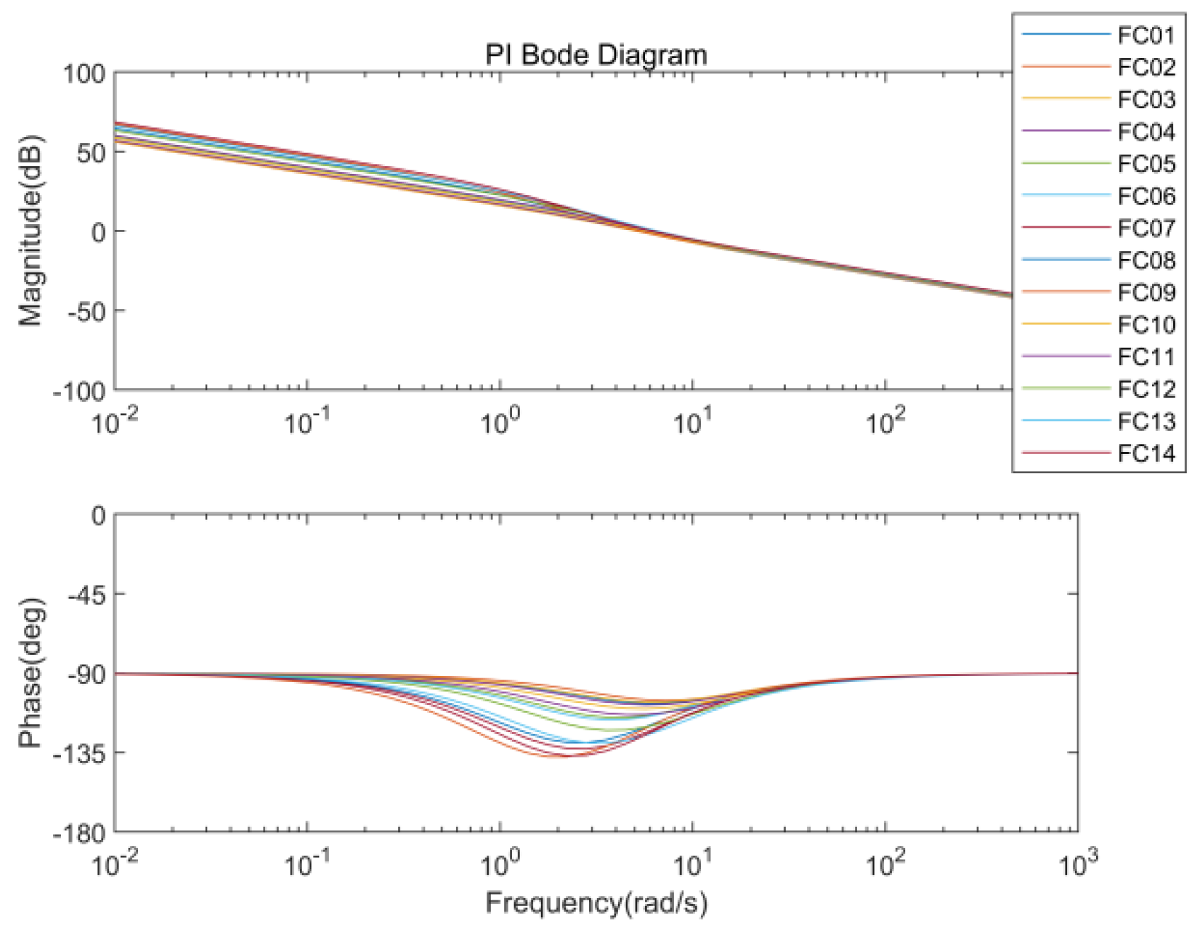
With Figure 2a, the stability of the FOLADRC system depends on the closed-loop made of  C ( s )  and the plant. To analyze the stability, we draw the Bode diagrams of  C ( s ) P i ( s ) , i = 1 , 2 , , 14  in Figure 8, while the PMs and the gain crossover frequencies  ω γ  are listed in Table 1. To compare, PI control (22) is also used for the 14 linearized models as shown in Figure 3. Bode diagrams of  C P I ( s ) P i ( s ) , i = 1 , 2 , , 14  are drawn in Figure 9, while the PMs and  ω γ  are also listed in Table 1.
Table 1 and Figure 8 and Figure 9 show that both FOLADRC and the PI control can stably control the 14 flight conditions. In addition, in every line of Table 1, the PM of FOLADRC is bigger than that of the PI control, while the gain crossover frequency of FOLADRC and of PI control are similar.
PM is an important design specification for control systems. It characterizes the ability of the closed-loop to resist the unmodeled time-delay. Insufficient PM may result in instability or poor transient performance. Turbofan engine controls usually need a large PM. The reason is that when modeling a turbofan engine, the time-delays of combustion and other processes are usually ignored. Thus, when designing the controller, it is necessary to guarantee enough PM to deal with the unmodeled time-delay. A typical specification of PM is no less than 45° [1], but in China, sometimes a larger PM such as 60° or 70° is suggested.
Table 1 shows that FOLADRC meets the PM specification of 60° for all 14 conditions. The least is 63.0° for FC13, while the greatest is 86.8° for FC02.

3.3. Transient Performance

Now we compare the transient performances between FOLADRC and PI control. Let the reference be a step of 100 r/min.
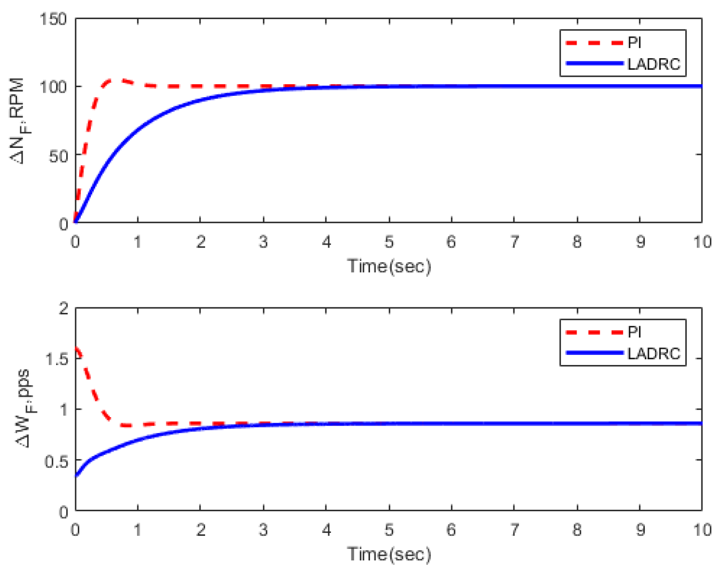
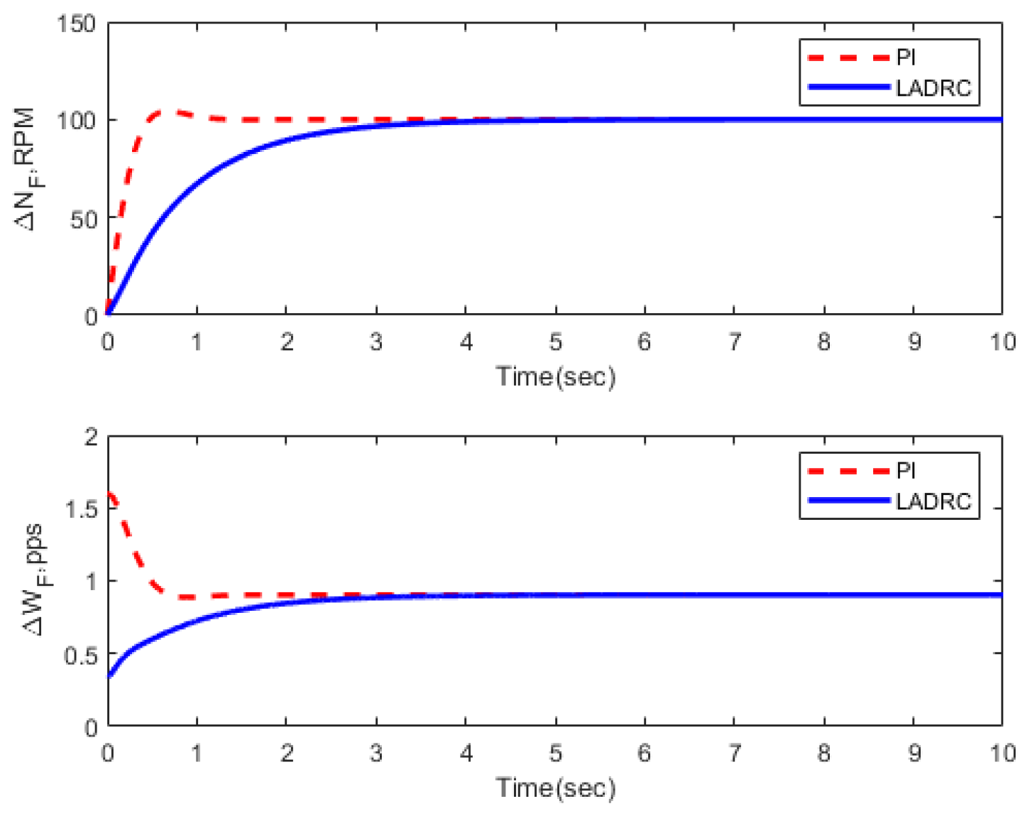
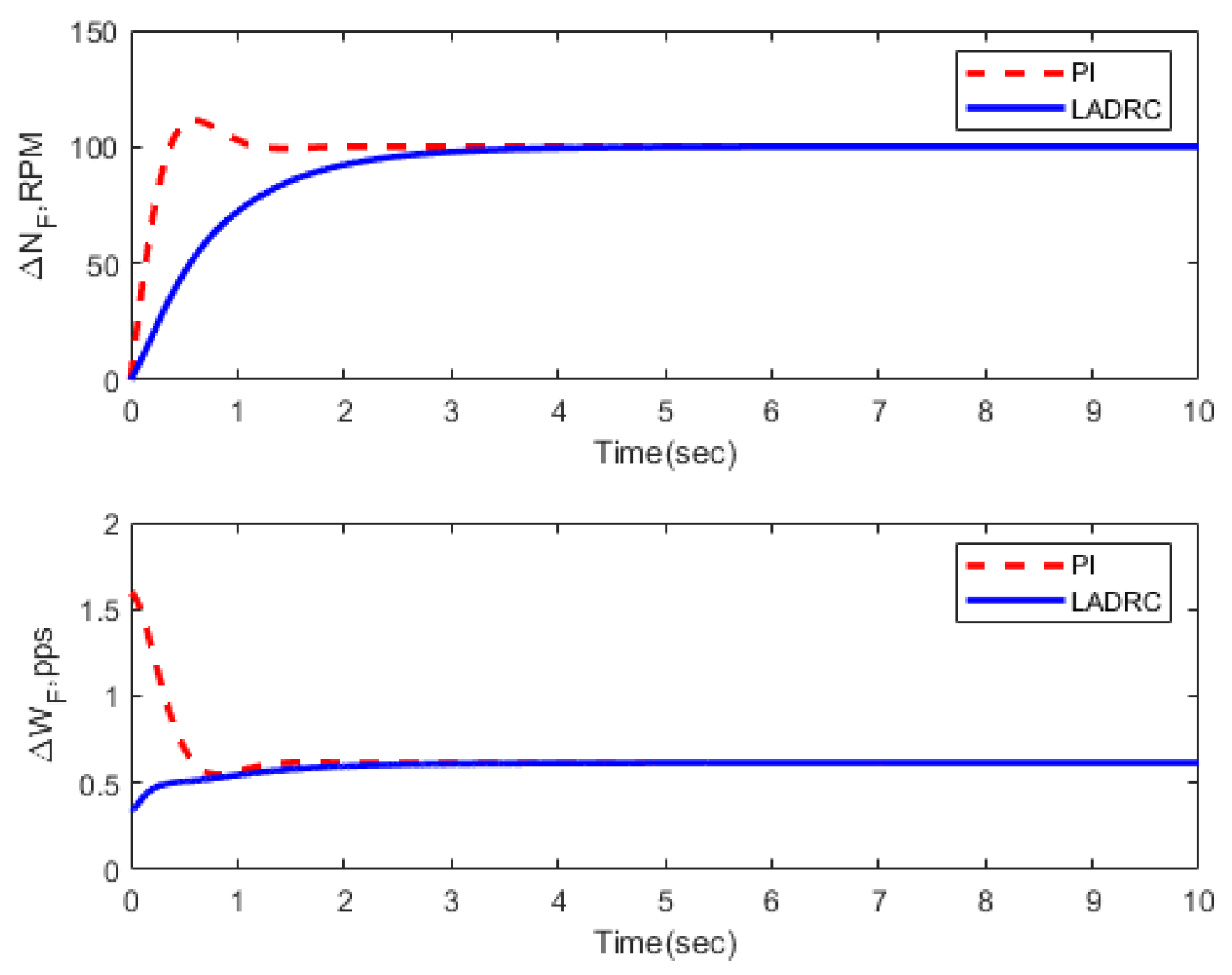
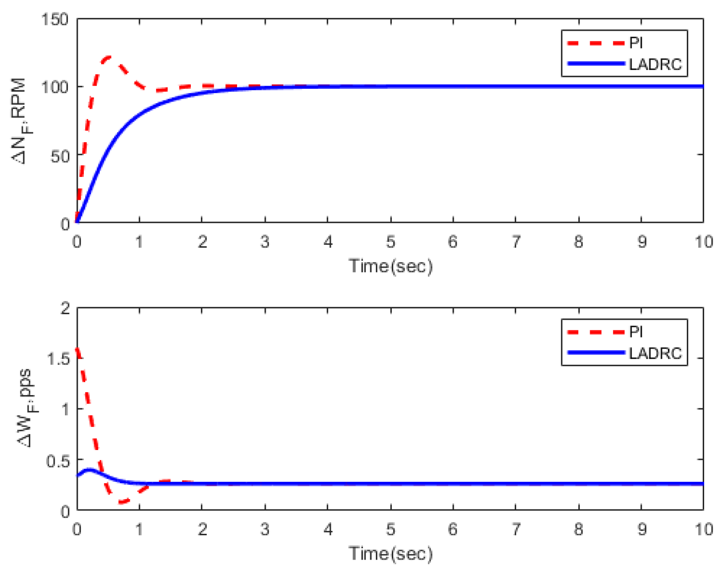
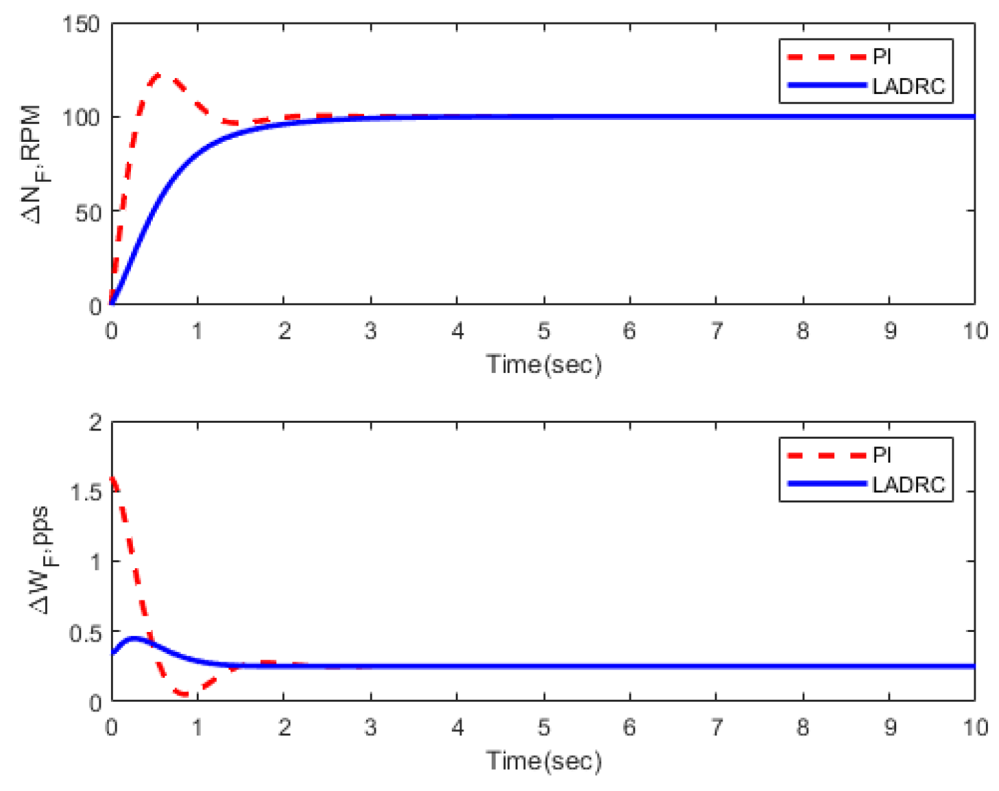
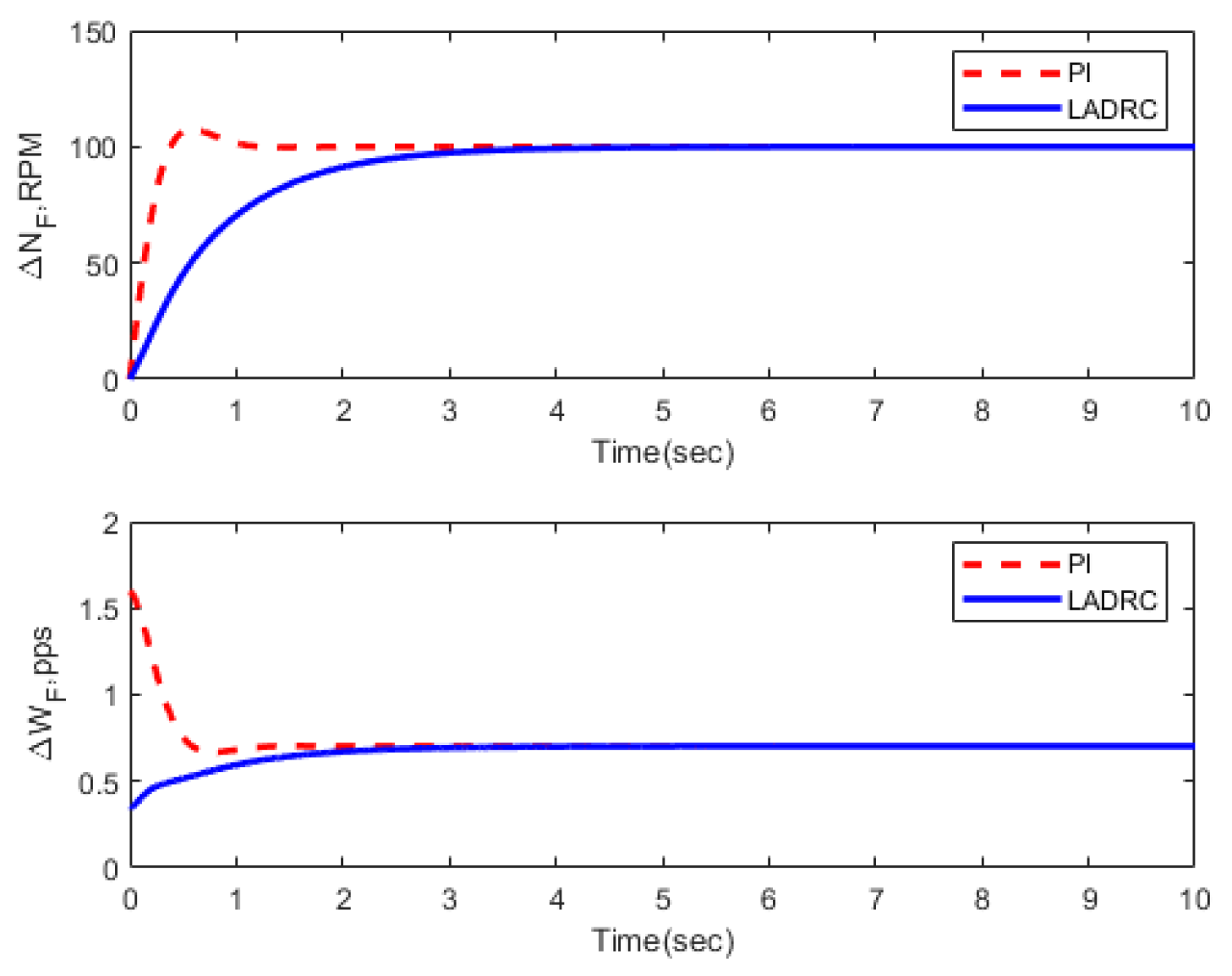
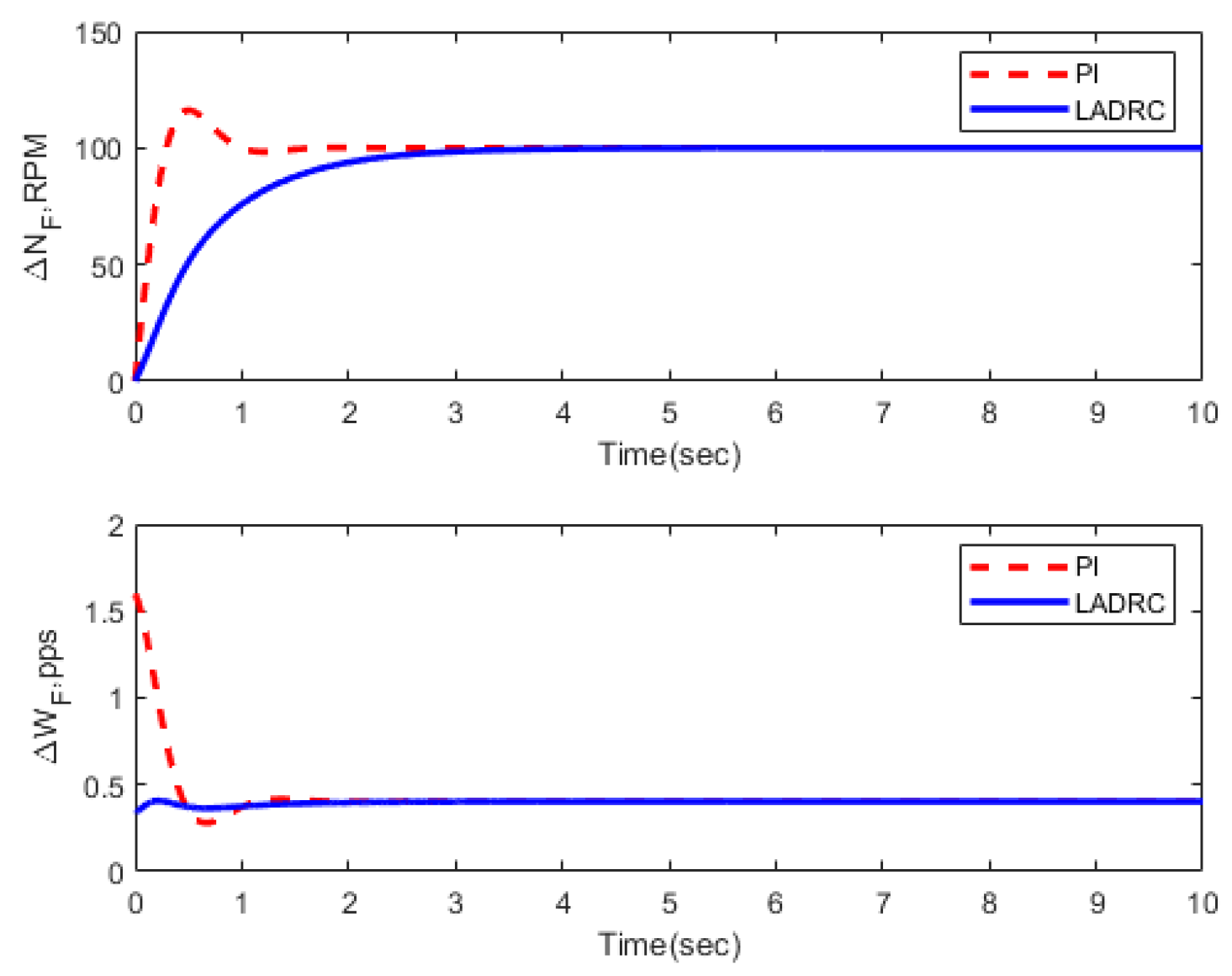
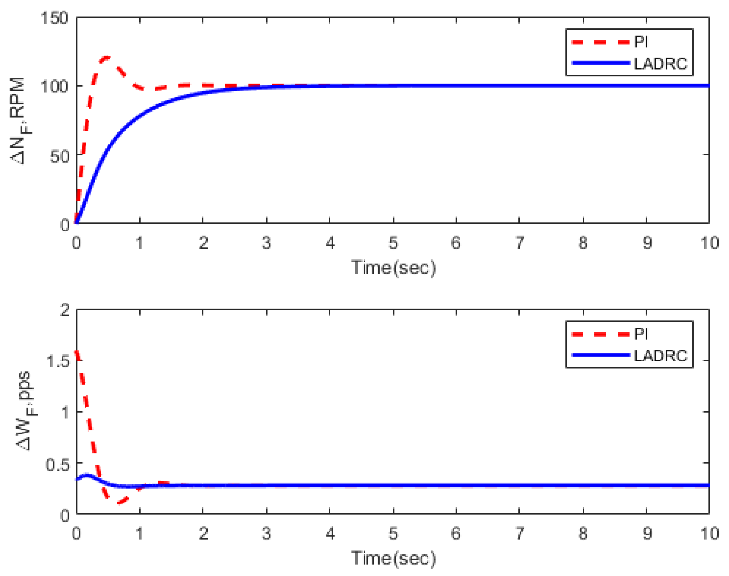
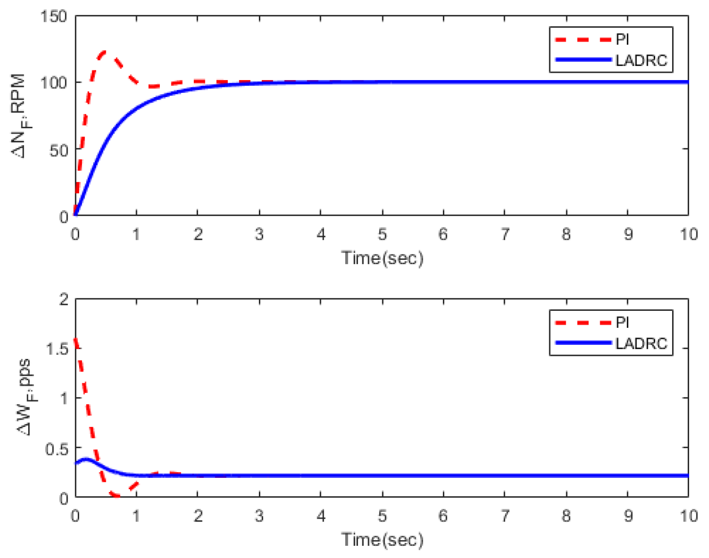
All 14 linearized models are simulated with Matlab 2016. The results are drawn in Figure 10, Figure 11, Figure 12, Figure 13, Figure 14, Figure 15, Figure 16, Figure 17, Figure 18, Figure 19, Figure 20, Figure 21, Figure 22 and Figure 23. In all simulations, FOLADRC performs better than PI control. In particular, FOLADRC for FC07–FC09 and FC12–FC14 has PMs less than 69.8°, which is the PM PI control for FC10. But the former six have no overshoot, while the latter one has. The reason is the pre-filter  F P ( s )  in Figure 2b.
Overshoot is another key specification for control systems. It is the maximum percentage the step response overshoots it final value. For a turbofan engine, it helps to evaluate how fast the thrust is stabilized to its final value, and its typical value is less than 5% [1,2].
Generally speaking, the larger the PM, the less is the overshoot. That is why sometimes PM is suggested at no less than 60°. But because of the complex relationship between frequency response and time domain performance, it is not easy to meet 60° of PM and 5% of overshoot simultaneously. For example, with Table 1 and Figure 14 and Figure 15 and Figure 19, Figure 20 and Figure 21, we know that when used for FC05, FC06, FC10, FC11, and FC12, the PI control (22) has a PM greater than 60°, but an overshoot greater than 5%. In order to ensure overshoot specification with PM specification, it is often necessary to repeat trial and error.
As discussed in Section 2, with the pre-filter  F P ( s ) , FOLADRC has a wonderful ability to suppress overshoot. Figure 10, Figure 11, Figure 12, Figure 13, Figure 14, Figure 15, Figure 16, Figure 17, Figure 18, Figure 19, Figure 20, Figure 21, Figure 22 and Figure 23 show the ability. All 14 step responses of FOLADRC have no overshoot, especially for FC13 and FC14 where the PMs are less 65.0°. Thus, FOLADRC can suppress overshoot and obtain good transient performance when PM is not quite large. This is a property of FOLADRC superior to PI control.

4. Discussion

With the discussion in Section 2, FOLADRC can be viewed as a PI control with two filters. With the simulations and analysis in Section 3, we conclude that FOLADRC is a promising approach to control a turbofan engine. It can guarantee sufficient PM and good transient performance simultaneously. It is more robust than PI control. Furthermore, it is possible to replace several PI controllers with one FOLADRC controller. FOLADRC (7)–(8) with parameters (23) is an example that can control FC01–FC14.
The robustness of FOLADRC may bring the following three conveniences for turbofan-engine control systems.
(1)
To lessen the number of controllers and simplify the control system. With the knowledge that one FOLADRC controller can replace several PI controllers, it is unnecessary to design a controller for each flight condition. Instead, the flight conditions can be divided into several sets, and one common FOLADRC controller is designed for the flight conditions in each set. In this way, the number of the controllers is lessened, the controller switching/tuning becomes infrequent, and the control system is simplified. Extremely, if one FOLADRC controller can be used for all flight conditions, the controller switching/tuning algorithm becomes unnecessary.
(2)
To simplify the stability analysis of the turbofan-engine control system. As discussed in Section 1, when many PI controllers work in the adaptive control framework, stability analysis is a time-consuming work. The more the controllers, the more complicated is the stability analysis. Thus, to replace several PI controllers with one FOLADRC controller can simplify the stability analysis.
(3)
To simplify the modeling of a turbofan engine. The number of flight conditions in the entire flight envelope may be lessened because several flight conditions that share a common FOLADRC controller can be merged to one. By lessening the number of flight conditions, the money and time on establishing a mathematical model for the engines can be saved.
However, the investigations of this paper are mainly with simulations. They are far away from really updating PI control with FOLADRC in controlling turbofan engines. Further theoretical studies, especially on how to design FOLADRC for several flight conditions, is the work in the next stage. Whole-flight-envelope simulations and possible experiments are necessary to compare FOLADRC and adaptive PI control for turbofan engines.

Author Contributions

Conceptualization, H.-Y.J.; methodology, H.-Y.J. and Y.C.; simulations, Y.C.; writing—original draft preparation, H.-Y.J. When doing the work of this paper, Y.C. was a graduate student at Xiamen University. All authors have read and agreed to the published version of the manuscript.

Funding

This research was funded by the National Nature Science Foundation of China, Grant number 62273285.

Acknowledgments

Thanks to Hui Wan for pointing out Figure 2b in personal discussions.

Conflicts of Interest

The authors declare no conflict of interest.

Nomenclature

AltAltitude
EPREngine Pressure Ratio
HPCHigh Pressure Compressor
HPTHigh Pressure Turbine
LPCLow Pressure Compressor
PLAPower Lever Angle
PS30HPC outlet static pressure
T48HPT outlet total temperature
NfFan speed
NcCore speed
WFFuel flow rate
∆NfIncremental fan speed
∆NcIncremental core speed
∆WFIncremental fuel flow rate
PIProportional-integral
PIDProportional-integral-derivative
LQRLinear quadratic regulator
ADRCActive disturbance rejection control
LADRCLinear active disturbance rejection control
FOLADRCFirst-order linear active disturbance rejection control
SOLADRCSecond-order linear active disturbance rejection control
ESOExtended state observer
PMPhase margin
MAPSSModular aviation propulsion system simulation
CMAPSS-1Civilian modular aviation propulsion system simulation

Appendix A

Table A1. Six published flight conditions.
FC01FC05FC06FC07FC08FC09
Alt (ft)0.0010,000.0020,000.0025,000.0035,000.0042,000.00
Mach0.000.250.700.620.840.84
PLA (°)100.00100.00100.0060.00100.00100.00
W F  (pps)6.844.663.861.672.121.52
N f  (r/min)2388.002319.002324.001915.002223.002212.00
N c  (r/min)9051.008774.008719.008006.008346.008317.00
EPR1.301.261.080.941.021.02
T 48  (°R)2072.001947.001909.001534.001750.001744.00
P s 30  (psia)522.13371.76206.76163.94183.10130.51
LPC R-Line1.641.632.311.701.521.54
HPC R-Line1.951.961.982.032.002.03
F n  (lbf)86,636.0045,830.0025,774.0011,475.0013,552.009674.00
Table A2. The matrices and transfer functions of 14 flight conditions.
MatricesTransfer Functions
FC01   A = [ 3.8557 1.4467 0.4690 4.7081 ] ; B = [ 230.6739 653.5547 ] ; C = [ 1 0 ] .   P ( s ) = Δ N f Δ W F = 230 . 7 s + 2032 s 2 + 8.564 s + 17.47
FC02   A = [ 4.1804 1.5321 0.3244 4.9290 ] ; B = [ 231.8138 674.5305 ] ; C = [ 1 0 ] .   P ( s ) = Δ N f Δ W F = 231.8 s + 2176 s 2 + 9.109 s + 20.11
FC03   A = [ 4.0334 1.4777 0.5872 4.6338 ] ; B = [ 225.5204 627.2142 ] ; C = [ 1 0 ] .   P ( s ) = Δ N f Δ W F = 225 . 5 s + 1972 s 2 + 8 . 667 s + 17 . 82
FC04   A = [ 3.7401 1.4001 0.4752 4.5586 ] ; B = [ 231.5508 657.3084 ] ; C = [ 1 0 ] .   P ( s ) = Δ N f Δ W F = 231 . 6 s + 1976 s 2 + 8 . 299 s + 16 . 38
FC05   A = [ 2.9378 1.0937 0.4149 3.4793 ] ; B = [ 239.7745 688.5648 ] ; C = [ 1 0 ] .   P ( s ) = Δ N f Δ W F = 239 . 8 s + 1588 s 2 + 6 . 42 s + 9 . 776
FC06   A = [ 2.9150 1.0362 0.7871 3.4432 ] ; B = [ 239.3185 723.6188 ] ; C = [ 1 0 ] .   P ( s ) = Δ N f Δ W F = 239.3 s + 1574 s 2 + 6.358 s + 9.22
FC07   A = [ 1.7435 0.7642 0.5080 2.1737 ] ; B = [ 287.6845 891.1333 ] ; C = [ 1 0 ] .   P ( s ) = Δ N f Δ W F = 287.7 s + 1290 s 2 + 3.92 s + 3.41
FC08   A = [ 1.7852 0.6006 0.4678 21335 ] ; B = [ 252.1854 788.2555 ] ; C = [ 1 0 ] .   P ( s ) = Δ N f Δ W F = 252.2 s + 1012 s 2 + 3.919 s + 3.528
FC09   A = [ 1.2320 0.3757 0.2003 1.4073 ] ; B = [ 255.8006 789.9624 ] ; C = [ 1 0 ] .   P ( s ) = Δ N f Δ W F = 255.8 s + 657.7 s 2 + 2.64 s + 1.662
FC10   A = [ 3.6248 1.5373 0.9017 4.6475 ] ; B = [ 247.3701 685.2015 ] ; C = [ 1 0 ] .   P ( s ) = Δ N f Δ W F = 247.4 s + 2203 s 2 + 8.276 s + 15.48
FC11   A = [ 3.3384 1.4517 0.8547 4.2881 ] ; B = [ 262.2267 773.8465 ] ; C = [ 1 0 ] .   P ( s ) = Δ N f Δ W F = 262.2 s + 2248 s 2 + 7.627 s + 13.07
FC12   A = [ 2.6591 1.3162 0.5251 3.2409 ] ; B = [ 274.6438 814.3750 ] ; C = [ 1 0 ] .   P ( s ) = Δ N f Δ W F = 274.6 s + 1962 s 2 + 5.90 s + 7.927
FC13   A = [ 2.1668 1.2163 0.5305 2.7527 ] ; B = [ 293.1481 867.6547 ] ; C = [ 1 0 ] .   P ( s ) = Δ N f Δ W F = 293.2 s + 1862 s 2 + 4.92 s + 5.319
FC14   A = [ 1.8470 0.7489 0.0996 1.4302 ] ; B = [ 305.0075 973.0158 ] ; C = [ 1 0 ] .   P ( s ) = Δ N f Δ W F = 305 s + 1165 s 2 + 3.278 s + 2.567

References

  1. Jaw, L.C.; Mattingnly, J.D. Aircraft Engine Controls: Design, System Analysis, and Health Monitoring; AIAA: Reston, VA, USA, 2009. [Google Scholar]
  2. Richter, H. Advanced Control of Turbofan Engines; Springer: New York, NY, USA, 2011. [Google Scholar]
  3. Miklosovic, R.; Gao, Z. A dynamic decoupling method for controlling high performance turbofan engines. IFAC Proc. Vol. 2005, 38, 532–537. [Google Scholar] [CrossRef] [Green Version]
  4. Yao, H. Full Authority Digital Electronic Control System for Aero-Engine; China Aviation Publishing & Media Co., Ltd.: Beijing, China, 2014. (In Chinese) [Google Scholar]
  5. Han, J. Auto-disturbance-rejection controller and its applications. Control Decis. 1998, 13, 19–23. (In Chinese) [Google Scholar]
  6. Han, J. From PID to active disturbance rejection control. IEEE Trans. Ind. Electron. 2009, 56, 900–906. [Google Scholar] [CrossRef]
  7. Huang, Y.; Xue, W. Active disturbance rejection control: Methodology and theoretical analysis. ISA Trans. 2014, 53, 963–976. [Google Scholar] [CrossRef] [PubMed]
  8. Feng, H.; Guo, B.-Z. Active disturbance rejection control: Old and new results. Annu. Rev. Control 2017, 44, 238–248. [Google Scholar] [CrossRef]
  9. Zheng, Q.; Gao, Z. Active disturbance rejection control: Some recent experimental and industrial case studies. Control Theory Technol. 2018, 16, 301–312. [Google Scholar] [CrossRef]
  10. Gao, Z. Scaling and bandwidth parameterization based controller tuning. In Proceedings of the American Control Conference, Denver, CO, USA, 4–6 June 2003; pp. 4989–4996. [Google Scholar]
  11. Yang, R.; Sun, M.; Chen, Z. Active disturbance rejection control on first-order plant. J. Syst. Eng. Electron. 2009, 22, 95–102. [Google Scholar] [CrossRef]
  12. Liu, Y.; Nie, L.; Zhang, J.; Yang, X. Research on Pressure Control Algorithm of a Flow Adjustable Gas Generator Based on linear Active Disturbance Rejection Control. J. Propuls. Technol. 2015, 36, 1768–1773. (In Chinese) [Google Scholar]
  13. Sun, L.; Hua, Q.; Li, D.; Pan, L.; Xue, Y.L.; Lee, K.Y. Direct energy balance based active disturbance rejection control for coal-fired power plant. ISA Trans. 2017, 70, 486–493. [Google Scholar] [PubMed]
  14. He, T.; Wu, Z.; Shi, R.; Li, D.; Sun, L.; Wang, L.; Zheng, S. Maximum Sensitivity-Constrained Data-Driven Active Disturbance Rejection Control with Application to Airflow Control in Power Plant. Energies 2019, 12, 231. [Google Scholar] [CrossRef] [Green Version]
  15. Zhang, F.; Xue, Y.; Li, D.; Wu, Z.; He, T. On the Flexible Operation of Supercritical Circulating Fluidized Bed: Burning Carbon Based Decentralized Active Disturbance Rejection Control. Energies 2019, 12, 1132. [Google Scholar] [CrossRef] [Green Version]
  16. Shi, G.; Wu, Z.; Guo, J.; Li, D.; Ding, Y. Superheated Steam Temperature Control Based on a Hybrid Active Disturbance Rejection Control. Energies 2020, 13, 1757. [Google Scholar] [CrossRef] [Green Version]
  17. Wu, Z.; Li, D.; Xue, Y.; Sun, L.M.; He, T.; Zheng, S. Modified active disturbance rejection control for fluidized bed combustor. ISA Trans. 2020, 102, 135–153. [Google Scholar] [CrossRef] [PubMed]
  18. Chiumeo, R.; Raggini, D.; Veroni, A.; Clerici, A. Comparative Analysis of PI and ADRC Control through CHIL Real Time Simulations of a DC-DC DAB into a Multi-Terminal MVDC/LVDC Distribution Network. Energies 2022, 15, 7631. [Google Scholar] [CrossRef]
  19. Wu, Z.; Gao, Z.; Li, D.; Chen, Y.; Liu, Y. On transitioning from PID to ADRC in thermal power plants. Control Theory Technol. 2021, 19, 3–18. [Google Scholar] [CrossRef]
  20. Zhang, C.; Zhu, J.; Gao, Y. Order and parameter selections for active disturbance rejection controller. Control Theory Appl. 2014, 31, 1480–1485. (In Chinese) [Google Scholar]
  21. Jin, H.; Chen, Y.; Lan, W. Replacing PI control with first-order linear ADRC. In Proceedings of the IEEE 8th Data Driven Control and Learning Systems Conference (DDCLS), Dali, China, 24–27 May 2019; pp. 1097–1101. [Google Scholar]
  22. Zhong, S.; Huang, Y.; Guo, L. A parameter formula connecting PID and ADRC. Sci. China Inf. Sci. 2020, 63, 192203. [Google Scholar] [CrossRef]
  23. Jin, H.; Song, J.; Lan, W.; Gao, Z. On the characteristics of ADRC: A PID interpretation. Sci. China Inf. Sci. 2020, 63, 209201. [Google Scholar]
  24. Liu, Y.; Frederick, D.K.; DeCastro, J.A.; Litt, J.S.; Chan, W.W. Users Guide for the Commercial Modular Aero-Propulsion System Simulation (C-MAPSS) (Ver. 2.0). NASA Technical Manuscript 2012. Available online: https://ntrs.nasa.gov/api/citations/20120003211/downloads/20120003211.pdf (accessed on 2 February 2023).
  25. Franklin, G.F.; Powell, J.D.; Emami-Naeini, A. Feedback Control of Dynamic Systems, 8th ed.; Publishing House of Electronics Industry: Beijing, China, 2021. [Google Scholar]
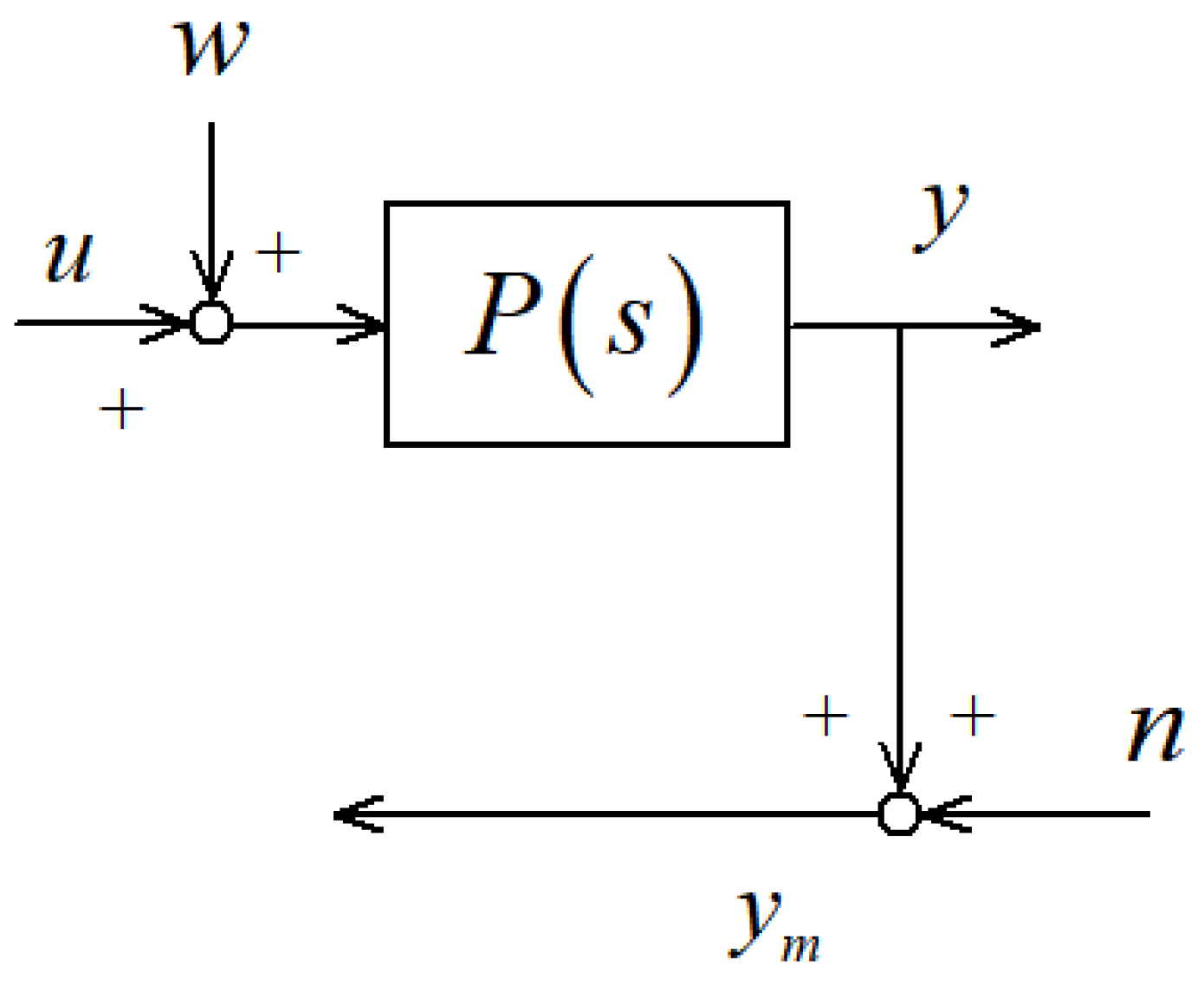
Figure 1. The block diagram of the plant.
Energies 16 02743 g001
Figure 3. The block diagram of PI control.
Energies 16 02743 g003
Figure 4. Typical Bode diagram of  F L ( s ) , where  l 1 = 1 β 1 = 20 .
Energies 16 02743 g004
Figure 5. Typical Bode diagram of  F P ( s ) , where  l 1 = 1 β 1 = 20 β 2 = 100 .
Energies 16 02743 g005
Figure 6. Typical Bode diagrams of  W P I ( s ) W A D R C ( s ) , and  F P ( s ) W A D R C ( s ) . The parameters are:  l 1 = 1 β 1 = 20 β 2 = 100 b 0 = 2 . The plant  P ( s ) = 2.25 / ( 1 + 1.5 ) 2 .
Energies 16 02743 g006
Figure 7. Typical step responses of FOLADRC and PI control. The parameters are:  l 1 = 1 β 1 = 20 β 2 = 100 b 0 = 2 . The plant  P ( s ) = 2.25 / ( 1 + 1.5 ) 2 .
Energies 16 02743 g007
Figure 8. Bode plots of  C ( s ) P i ( s ) , i = 1 , 2 , , 14 .
Energies 16 02743 g008
Figure 9. Bode plots of  C P I ( s ) P i ( s ) , i = 1 , 2 , , 14 .
Energies 16 02743 g009
Figure 10. Step response of FC01.
Energies 16 02743 g010
Figure 11. Step response of FC02.
Energies 16 02743 g011
Figure 12. Step response of FC03.
Energies 16 02743 g012
Figure 13. Step response of FC04.
Energies 16 02743 g013
Figure 14. Step response of FC05.
Energies 16 02743 g014
Figure 15. Step response of FC06.
Energies 16 02743 g015
Figure 16. Step response of FC07.
Energies 16 02743 g016
Figure 17. Step response of FC08.
Energies 16 02743 g017
Figure 18. Step response of FC09.
Energies 16 02743 g018
Figure 19. Step response of FC10.
Energies 16 02743 g019
Figure 20. Step response of FC11.
Energies 16 02743 g020
Figure 21. Step response of FC12.
Energies 16 02743 g021
Figure 22. Step response of FC13.
Energies 16 02743 g022
Figure 23. Step response of FC14.
Energies 16 02743 g023
Table 1. Phase margin comparison.
ConditionFOLADRCPI Control
PM (°) ω γ  (rad/s)PM (°) ω γ  (rad/s)
FC0184.65.0973.0°5.27
FC0286.85.1075.2°5.28
FC0386.24.9073.8°5.12
FC0483.55.1272.0°5.29
FC0576.35.2665.6°5.40
FC0675.65.2464.8°5.38
FC0765.46.0057.5°6.03
FC0868.95.2258.4°5.36
FC0967.76.0756.8°5.24
FC1079.45.5869.8°5.68
FC1174.76.0066.7°6.03
FC1267.46.2760.4°6.27
FC1363.06.5557.0°6.52
FC1464.36.2157.1°6.22
Disclaimer/Publisher’s Note: The statements, opinions and data contained in all publications are solely those of the individual author(s) and contributor(s) and not of MDPI and/or the editor(s). MDPI and/or the editor(s) disclaim responsibility for any injury to people or property resulting from any ideas, methods, instructions or products referred to in the content.