Article

Evaluating the Effect of Ammonia Co-Firing on the Performance of a Pulverized Coal-Fired Utility Boiler

School of Energy and Environment, Southeast University, Nanjing 210096, China
*
Author to whom correspondence should be addressed.
Energies 2023, 16(6), 2773; https://doi.org/10.3390/en16062773
Submission received: 9 February 2023 / Revised: 12 March 2023 / Accepted: 15 March 2023 / Published: 16 March 2023

Abstract

:
Ammonia (NH3), as a derivative of hydrogen and energy carrier, is regarded as a low-carbon fuel provided that it is produced from a renewable source or a carbon abated process of fossil fuel. Co-firing ammonia with coal is a promising option for pulverized coal-fired power plants to reduce CO2 emission. Applying the co-firing in an existing pulverized coal-fired boiler can achieve satisfying combustion performance in the furnace but may affect the boiler performance. In the present work, a thermal calculation method was employed to evaluate the impact of ammonia co-firing on the boiler performance of an existing 600 MW supercritical utility boiler, covering the co-firing ratio range up to 40% (on heat basis). The calculations indicated that, as compared to sole coal combustion, co-firing ammonia changed the volume and composition and consequently the temperature and heat transfer characteristics of the flue gas. These resulted in increased variations in the heat transfer performance of the boiler with increasing of the co-firing ratio. The evaluations revealed that co-firing up to 20% ammonia in the existing boiler is feasible with the boiler performance not being considerably affected. However, the distribution of the heat transferred from the flue gas to boiler heat exchangers is significantly deteriorated at higher ratios (30% and 40%), resulting in over-temperature of the superheated steam, under-temperature of the reheated steam and considerable reduction in boiler thermal efficiency. It implies retrofits on the heat exchangers required for accommodating higher ratio co-firing in the existing boiler. The comparison study showed that co-firing 20% ammonia provides a superior boiler performance over co-firing 20% biomass producing gases and blast furnace gas.

1. Introduction

To limit global warming to 1.5 °C, phasing out unabated coal in the global power sector by 2030–2040 is inevitable [1]. Some countries have implemented or are on schedule to implement coal phase-out [2]. In China, coal is currently the dominant fuel for electricity generation to support rapid economic and social development, ensure energy security and stabilize electricity supply, and is expected to remain as a major power source in the near term of transiting to a low-carbon future. However, the coal power industry is also the biggest CO2 emitter, accounting for 34% of national carbon emissions [3]. China has committed to achieve carbon peaking before 2030 and carbon neutrality by 2060. In such a circumstance, the coal power industry is under increasingly great pressure to reduce CO2 emissions. Power plant operators are pursuing decarbonization technologies, among them low-carbon fuels including biomass [4,5] and hydrogen-containing fuels, mainly ammonia (NH3) [6,7], to partially or fully substitute coal and they are regarded as promising options. Switching from coal to these fuels allows existing coal-fired power plants to gradually become low-carbon generators with continuous operation to generate dispatchable electricity while retaining a large part of the existing assets [2,7,8].
Ammonia can be burned in pure oxygen or air, producing only water and nitrogen, and is a potential carbon-free hydrogen fuel provided that it is produced from a renewable source or a carbon abated process of fossil fuel. It is proven that ammonia can be burned directly in internal combustion engines, gas turbines and coal-fired boilers [9,10]. As a fuel, ammonia has various advantageous characteristics including high volumetric energy density, low unit energy storage cost and well-established storage and transport infrastructure [10], and is particularly suitable to be utilized on large scales in existing pulverized coal-fired power plants to partially replace coal through co-firing for CO2 reduction [11]. It therefore has been attracting broad research efforts for implementation in applications. Laboratory studies have been carried out for understanding the combustion characteristics and NOx formation, one of the most concerning issues, of ammonia burning under pulverized coal combustion conditions and pulverized coal/ammonia co-combustion under various co-firing ratios [12,13,14]. The studies showed that the ignition and flame propagation of pulverized coal/ammonia mixtures are comparable and even better than those of sole pulverized coal [15,16,17,18]. Moreover, the production of NOx can be suppressed by injecting the combustion air with a two-stage strategy and maintaining the independence of the ammonia/coal burner [19]. With the staged combustion strategy, the production of both char-NOx and fuel (NH3)-NOx can be reduced to achieve lower NOx emission as well as lower unburnt carbon in ash than during pure coal combustion [20]. It means that co-firing ammonia is capable of retaining or improving combustion performance as compared to pulverized coal combustion through combustion organization.
Trials and tests in bench- and pilot-scale combustion facilities and industrial-scale furnaces have demonstrated that co-firing ammonia in pulverized coal-fired power plants is feasible in terms of combustion performance and NOx suppression. The industrial trial of adding a small amount of ammonia (0.6–0.8%) to a 156 MW pulverized coal-fired unit [21,22] confirmed that ammonia is burned completely and co-firing ammonia had no impact on the boiler operation and NOx emission. Additionally, experiments on a full-scale coal-fired utility boiler showed that spraying urea in the fuel-rich zone could be carried out with reduced NOx emissions and full conversion of ammonia, the main decomposition product of urea [23], which indirectly proved the practical applicability of ammonia co-firing. Tamura et al. [12] investigated co-firing coal and NH3 in a 1.2 MWth furnace with a single horizontal burner. They observed the same combustion performance of ammonia co-firing as pulverized coal combustion in terms of ignition, flame temperature and flue gas emissions, no ammonia slip and similar NOx emissions up to 30% co-firing with the designed burner and ammonia injection. Hiroki et al. [24] tested co-firing NH3 with pulverized coal in a 10 MWth combustion facility with a swirl burner and also showed that, at co-firing ratios up to 20%, NOx could be limited to the same level as for coal firing and a stable flame was maintained by supplying ammonia through the center of the coal burner. Niu et al. [25] conducted industrial tests on a 40 MWth facility installed with a full-scale co-firing burner, demonstrating that co-firing 0–25% NH3 could achieve good combustion stability and burnout of both coal and ammonia and control NOx emissions at low levels through air staging. Besides experimental studies, cost-effective numerical simulations were also employed to investigate co-firing ammonia in pulverized coal-fired facilities [12,26,27,28]. The results represented the experimental observations at lower co-firing ratios and also explored the combustion performance and NOx formation at higher ratios. The investigations confirmed that co-firing ammonia at lower ratios retains similar combustion performance as pulverized coal combustion [12,26], however, the burnouts of both fuels may deteriorate significantly at co-firing ratios of above 40% [27] despite low NOx emissions still being achievable [26,27,28]. Both the experimental and numerical studies suggested the necessity and significance of burner design and combustion organization for higher ratios of ammonia co-firing in pulverized coal-fired furnaces.
While most of the previous studies were performed on the combustion performance and NOx emissions in pulverized coal-fired furnaces, few addressed the effect of ammonia co-firing on the boiler thermal performance [6,11]. It is well known that pulverized coal-fired utility boilers are generally designed for specific coals. As a gaseous fuel, however, ammonia has significantly different properties from coals, which may affect the performance, such as heat transfer of an existing boiler when ammonia is co-fired. Genichiro et al. [11] evaluated the boiler efficiency and material balance of a 1000 MW pulverized coal-fired boiler co-firing 20% ammonia. They observed comparable performance with coal combustion and nevertheless proposed some retrofits required for improvement. Xu et al. [6] assessed the performance of a 600 MW boiler co-firing ammonia up to 20% by using exergy analysis and found the boiler exergy efficiency decreased with increasing co-firing ratio, implying that the boiler performance may deteriorate further at higher co-firing ratios. To accommodate higher ratios of co-firing without compromising the performance may require boiler retrofits, and it relies on assessing the impact of co-firing on boiler heat transfer performance [19]. However, there is still a lack of studies on the heat transfer performance of existing boilers co-firing ammonia, particularly at relatively higher ratios.
The present work was to evaluate the effect of ammonia co-firing on the heat transfer performance of an existing pulverized coal-fired boiler over a wide range of co-firing ratios, up to 40%, by using a thermal calculation method, aimed at the technological issue of developing higher ratios for co-firing applications with boiler performance that is comparable to sole coal combustion. Considering co-firing ammonia is new but co-firing other gaseous fuels including biomass gas and blast furnace gas (BFG) is an existing technology applied in coal power plants, the comparison was also made with co-firing of these fuels based on thermal calculation analyses with the aim of exploring the applicability of existing gaseous fuel co-firing technologies for higher ratios of ammonia co-firing to improve boiler performance.

2. Method for Evaluating Boiler Performance

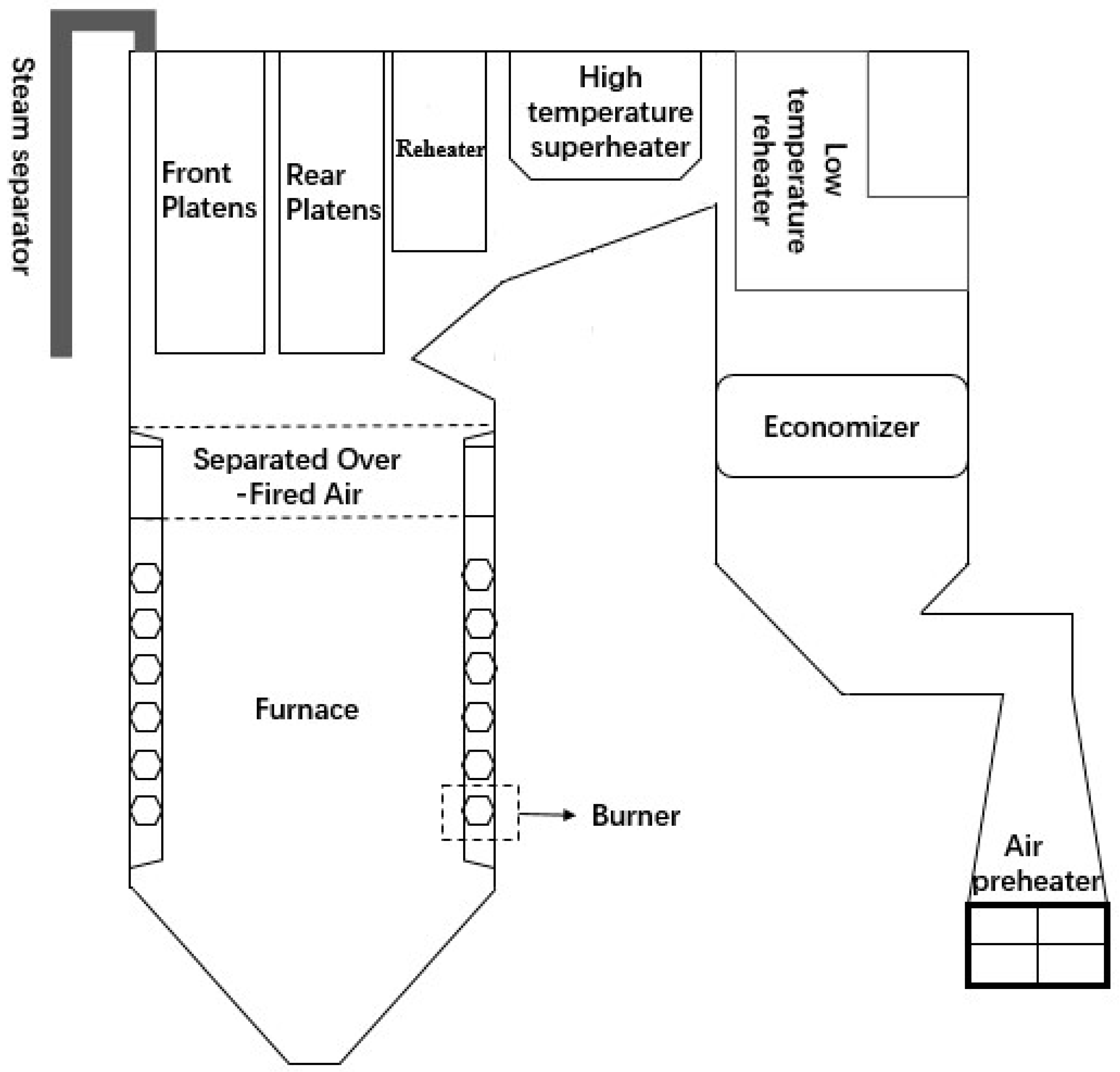
2.1. Overview of the Existing Pulverized Coal-Fired Utility Boiler

The evaluation on the boiler performance of ammonia co-firing was conducted with an existing 600 MW pulverized coal-fired utility boiler. The layout of the boiler is schematically shown in Figure 1. The unit is a typical Benson-type supercritical boiler, tangentially fired with 24 low-NOx pulverized coal burners installed in six layers at the furnace corners. The boiler was designed to burn bituminous coal with 20 pulverized coal burners in five layers to achieve the output of the maximum continuous rating (MCR). The pulverized coal burners and associated secondary air ports are distributed evenly in the lower furnace and a set of separated over-fired air ports are arranged above the burner zone for air staging to realize low NOx combustion. The properties of the pulverized coal are listed in Table 1.
After combustion in the lower furnace, the flue gas flows through the upper furnace, in which two stages of platen superheater are installed, horizontal convection pass with high-temperature reheater and superheater, second convection pass with low-temperature reheater and economizer and then the air preheater and finally leaves the boiler. Along the flow process, the flue gas transfers the heat to the furnace water walls (evaporator) by radiation, to the platen superheaters through radiation and convection and to the high-temperature superheater and reheaters, low-temperature reheater, economizer and air preheater mainly by convection. The main designed thermal parameters of the boiler are presented in Table 2.

2.2. Thermal Calculation Analysis of Boiler Performance

The thermal calculation method was employed to evaluate the performance of the existing pulverized coal-fired boiler and the effect of ammonia co-firing on the boiler performance. A thermal calculation model for the boiler was established in the form of Microsoft Excel spreadsheet tables, following the standard method for thermal calculation analysis [29]. The model adheres to the law of energy conservation for the boiler and its heat exchangers, including the evaporator, superheaters, reheaters, economizer and air preheater. The method is standard and widely applied in boiler design and retrofit. Validation with the designed results of the boiler burning the pulverized coal proved the correctness and accuracy of the model calculation.
The thermal calculation was focused on the heat transfer from the flue gas to working fluids, including water/steam in the heat exchangers and air in air preheater. The flue gas temperatures are determined based on the balance between the heat transferred to the exchanger surface and heat released from the flue gas. The heat release is calculated by
Q p , g = φ I p I p
where φ is the thermal retention coefficient, set to be 0.99 determined by boiler thermal efficiency and heat dissipation losses; I p and I p represent the enthalpy of the flue gas at the inlet and outlet of the heat exchanger, respectively.
In the furnace, the flame transfers the heat by radiation between the flue gas and radiant heat exchange surfaces, expressed as
Q R = ψ F ε f σ 0 T 1 4 ,   k W
where ψ represents the effective fraction of the radiation heat flux between the flue gas and surfaces of ash fouling on the furnace wall, F is the surface area of the furnace’s surroundings walls, εf denotes the emissivity of the radiation between the flue gas and fouling surfaces, σ0 is the Stefan–Boltzmann constant and T1 is the average temperature of the flue gas. The radiation heat of Equation (2) is balanced with the heat released from the flue gas of Equation (1), i.e., the difference between the heat input and output of the calculated zone, to determine the heat transferred and flue gas temperatures.
High-temperature superheater and reheaters, low-temperature reheaters, economizers and air preheaters are heating surfaces dominated by convective heat exchange. The heat transferred from the flue gas to the working flows in these heat exchangers located in the convection passes is determined by
Q C = K H Δ t           with           K = 1 / α 1 + ε + 1 / α 2
where K is the heat transfer coefficient, H is the convective surface area, Δt is the average temperature difference between the flue gas and working fluid, ε represents the thermal resistance of ash layer deposited on the heat exchanger surface and α1 and α2 are the heat exchange coefficient on the flue gas and working fluid sides of the heat exchanger, respectively, both depending on the flow rate, temperature and thermo-physical properties of the flue gas or working fluid. The specific values of the parameters for heat transfer coefficient calculation are provided in Table A1 in Appendix A.
The front and rear platens in the upper furnace are the semi-radiant heating surface, which absorbs both the flue gas radiation in the furnace and convection heat of the contacted flue gas. So, α1 in Equation (3) is expressed as:
α 1 = ξ π d α c / 2 s x p + α r
where ξ is the correction factor of heat transfer coefficient on the flue gas side of the semi-radiant heating surface and is set to be 0.6, d is the diameter of the platen tubes, s is the longitudinal intercept of the tubes, αc and αr are heat exchange coefficients of convection and radiation of the flue gas, respectively, xp is the configuration angle coefficient of the main heating surface determined to be 0.87 and 0.9 for the front and rear platen, respectively. By substituting Equation (4) into Equation (3), the heat transferred to the platen superheaters can be calculated.
Through the heat transfer calculation, mainly the quantities of the heat transferred to the working fluid and the inlet and outlet temperatures of the flue gas and working fluid of the heat exchangers are determined.
The thermal efficiency of the boiler is determined based on the heat balance and calculated as the difference between the thermal input into the furnace and heat losses from the boiler, given as
η b = 100 q i
where qi denotes the heat losses, presented as the percentage of the boiler heat input. The losses include the sensible heat of the exhausted flue gas from the boiler, heat content of unburned gases, mainly CO and ammonia, in the flue gas, heat content of unburned carbon in the bottom and fly ash, heat released from the outside surfaces of the boiler by radiation and convection and the sensible heat of the bottom and fly ash.
For all the calculations of the co-firing cases and sole coal combustion, the boiler was assumed to be operated under the same conditions: the heat input with the fuels into the boiler is the same for achieving the MCR and the combustion air is supplied in similar distribution patterns for complete combustion of both the coal and gaseous fuels with an access air ratio of 1.2 as well as the same air-staging level. The ammonia co-firing ratio is presented as its percentage in the total heat input. Assuming that ammonia is completely burned to release heat, the amount of ammonia fuel can be obtained by dividing the amount of ammonia heat input by its low calorific value, and then the amounts of air required for combustion and flue gas produced as well as the composition of the flue gas can be determined.
For ammonia co-firing, thermal calculation analyses were performed for the boiler co-firing ammonia at various ratios up to 40% (on the heat basis). At co-firing ratios of less than 40%, the conversions of both coal and ammonia can be complete in the furnace [13,27], enabling the focus on investigating the impact of co-firing ratio on the boiler performance. While the co-firing ratio was changed for various co-firing cases, the thermal inputs of the mixed fuel into the furnace were kept the same as for the sole coal firing in the calculations. The lower heating value of ammonia was set to be 18.6 MJ/kg and other properties of ammonia used in the calculations were taken from the literature [30].

2.3. Co-Firing Gaseous Fuels with Pulverized Coal

Thermal calculations were also conducted for the boiler co-firing two biomass gases and a BFG at a co-firing ratio of 20% (on the heat basis), respectively. The results were compared with those from ammonia co-firing at the same ratio to further investigate the effects of ammonia co-firing on the boiler performance. The gaseous fuel properties for the calculations were taken from the literature [31,32]. The biomass gases were produced from air-blown gasification of two types of biomass, respectively; the BFG was the one co-fired in a pulverized coal-fired power plant. The compositions and lower heating values of these gaseous fuels are presented in Table 3.

3. Results and Discussion

3.1. Effects of Ammonia Co-Firing on the Boiler Performance

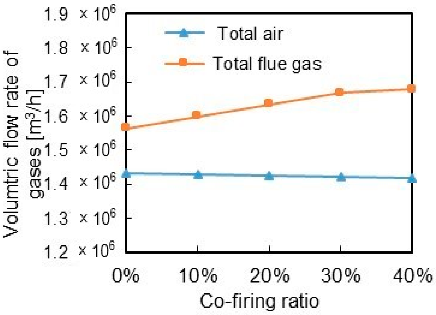
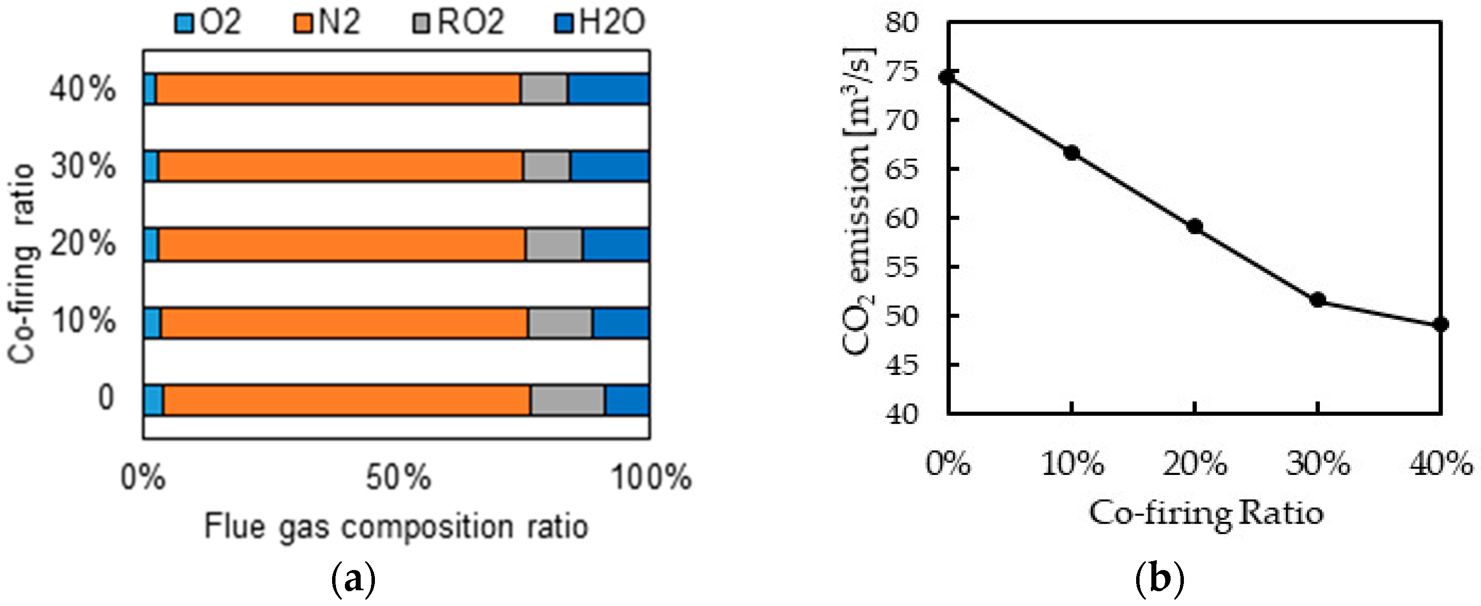
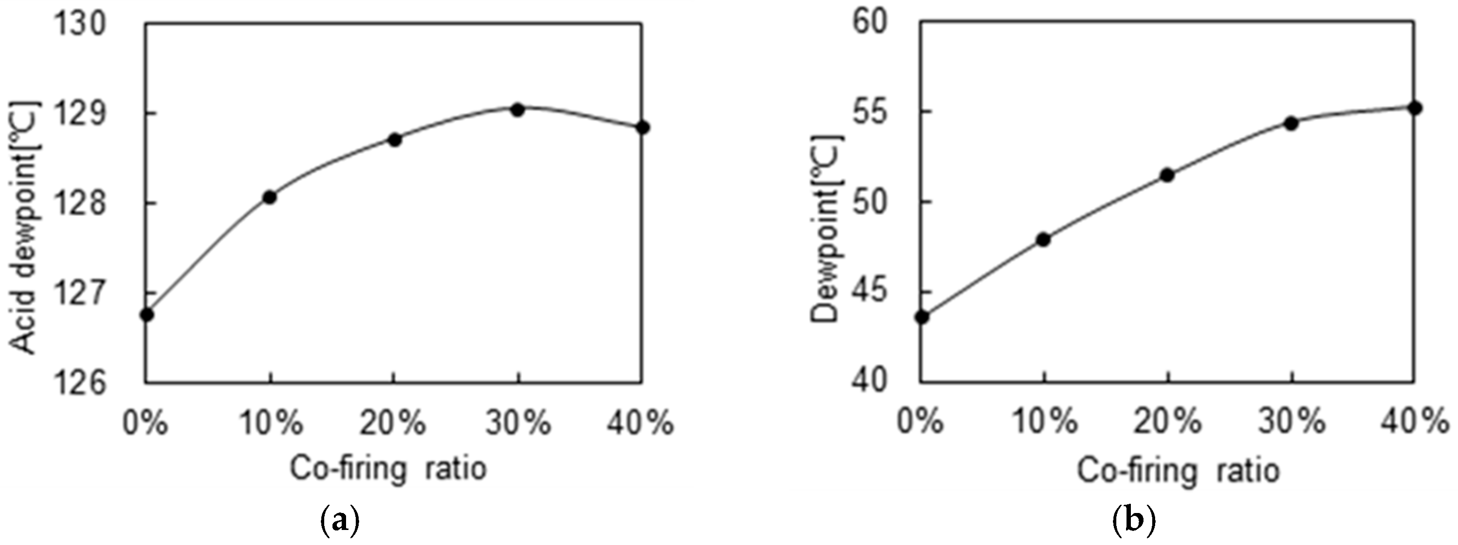
3.1.1. Flue Gas Properties

The calculated quantities of the air required for, and the flue gas produced from, the combustion of ammonia co-firing cases are presented in Figure 2, compared to those of sole pulverized coal combustion. The air requirement for co-firing slightly and linearly decreases with increasing of the co-firing ratio from 0 to 40%, implying less heat required for the air preheater to heat the combustion air for ammonia co-firing at higher ratios. In contrast, the volume of the flue gas produced increases considerably with the co-firing ratio. Therefore, the air supply fans of the unit can remain unchanged, but the capacity of the induced draft fan needs to increase for accommodating the increased flue gas flows at higher co-firing ratios.
As for the flue gas composition, the calculation results for various co-firing ratios are shown in Figure 3. It indicates that co-firing ammonia reduces CO2 production due to the fact that ammonia is a carbon-free fuel. With increasing of the co-firing ratio, CO2 concentration in the flue gas (shown as RO2, i.e., CO2 + SO2 in Figure 3a) declines considerably and CO2 emission gradually decreases from 74.3 m3/s for coal combustion to 49 m3/s for 40% co-firing (Figure 3b), neither proportionally to co-firing ratio. The fraction of H2O in the flue gas increases considerably and obviously with the co-firing ratio because H2O is the main product of ammonia combustion. Moreover, the fraction of the radiative gases, including RO2 and H2O, increases slightly (Figure 3a). The variations in the flue gas composition mean changes in thermo-physical properties of the flue gas after co-firing. For example, the specific heat capacity of the flue gas increases from 12.0 kJ/kg·K to 13.0 kJ/kg·K as the co-firing ratio increases from 10% to 40%. Such changes have an impact on the temperatures and heat transfer properties of the flue gas, as described below.
The content of fly ash in the flue gas decreases linearly with the co-firing ratio, as shown in Figure 4a. As fly ash is also the major radiation component of the flue gas, the decrease in the fly ash slightly reduces the radiation of the solid particles in the furnace. On the other hand, the slight increase in the fraction of the radiative gases in the flue gas (Figure 3) enhances the emissivity of the flame. As a consequence, the emissivity of the flame and flue gas in the furnace does not vary considerably as compared to the case of sole coal combustion, as indicated in Figure 4b. Nevertheless, the reduction of the fly ash reduced the ash-related heat losses such as unburned carbon in ash, having a favorable effect on boiler efficiency.

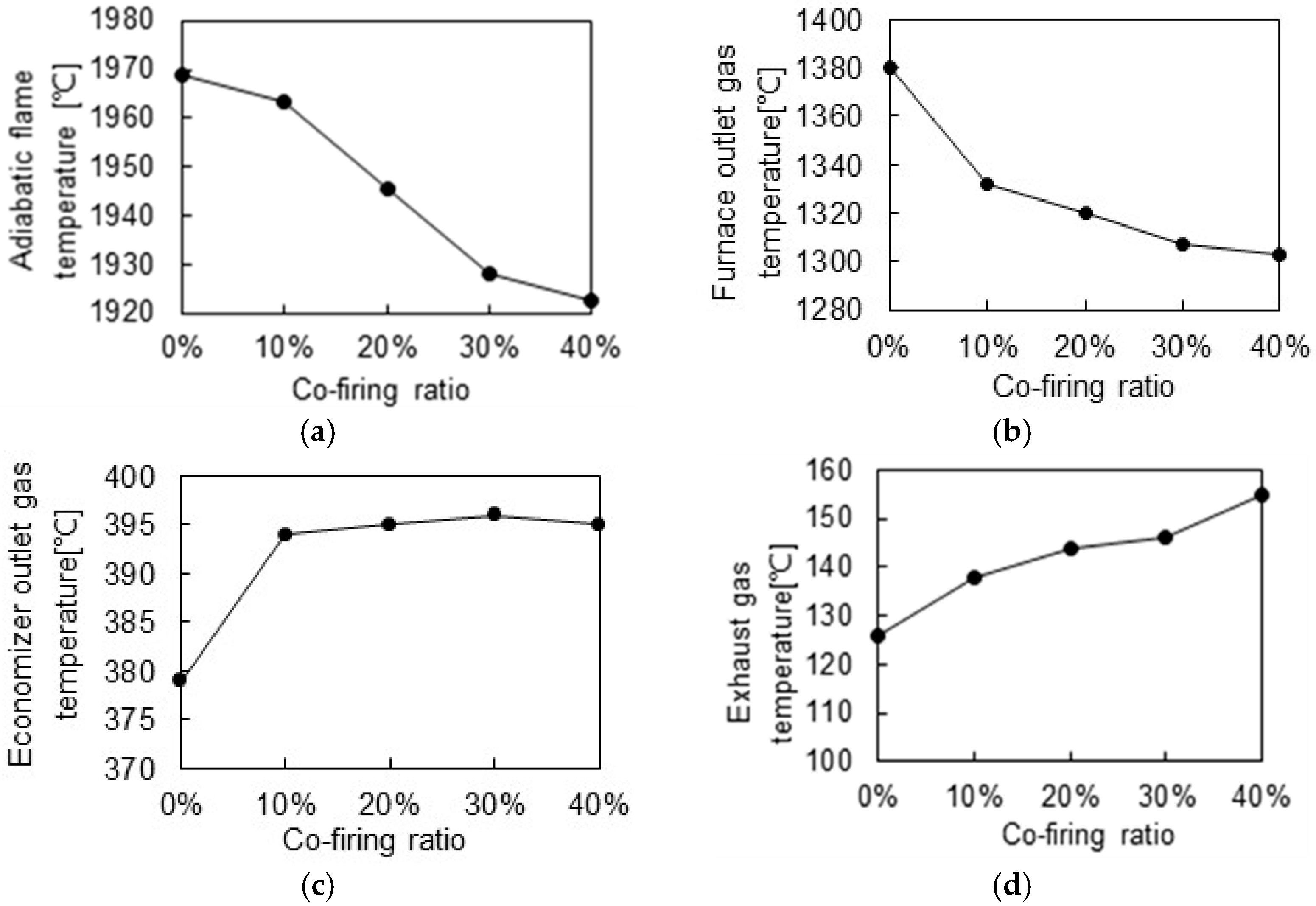
3.1.2. Flue Gas Temperatures in the Boiler

The calculated temperatures of the flue gas at some locations in the boiler, including the adiabatic flame temperature in the furnace and temperatures at the exit of the furnace (below the super-heater platens), outlet of the economizer and exit of the boiler (the outlet of the air preheater), varying with the co-firing ratio, are presented in Figure 5 to show the effect of ammonia co-firing on the combustion and heat transfer in the boiler.
As can be seen in Figure 5a, the adiabatic flame temperature in the furnace declines with the increase in co-firing ratio and it decreases by about 50 °C at 40% co-firing as compared to that of coal combustion. The main cause is the increase in the heat capacity of the flue gas due to the increase in the gas volume (Figure 2) and the change in the gas composition (Figure 3). In particular, the increase in H2O in the flue gas leads to the decrease in the adiabatic flame temperature. The reduction in the flame temperature may weaken the flame radiation and deteriorate combustion in the furnace. It implies that, in order to ensure the boiler radiation and combustion, the ammonia amount may be kept at a low proportion.
For the same reasons, the gas temperature at the furnace exit also decreases considerably at higher co-firing ratios, as shown in Figure 5b. This temperature is related to the properties of the combustion products and layout of the water walls and platens as well as the heat input into the furnace. As the co-firing ratio increased from 10% to 40%, the furnace temperature decreased by 48–77 °C relative to that for the sole coal combustion case (Figure 5b). The extent of the decrease is larger than that for the flame temperature mostly because of the greater increases in the volume and heat capacity of the exhausted gas from the furnace although less heat is released by radiation in the furnace mainly due to the lower flame temperature. The decreases in the flame and furnace exit temperature with increasing of the co-firing ratio are consistent with the observations in numerical simulations [12,26,27,28].
The decreased temperature of the flue gas exiting the furnace and the changes in flue gas composition lowering thermal conductivity are not conducive to the radiation and convection in the platen zone and convective heat transfer along the convection passes although the increased flue gas volume certainly enhances the convection. These effects gradually changed the trend of the gas temperature varying with the co-firing ratio as the flue gas flows through the heat exchangers in the convection passes. As a result, the gas temperature at the outlet of the economizer presents an increasing trend with increasing of the co-firing ratio, as compared to the sole coal combustion case (Figure 5c). Further downstream of the flue gas flow, Figure 5d shows that the boiler exhausted gas temperature nearly linearly increases by 12–28 °C with the co-firing ratio rising from 10% to 40%. The extent of the increase is significant as compared to the sole coal case. The causes are the increased flue gas volume (Figure 2) and inlet temperature (i.e., the outlet temperature of the economizer) (Figure 5c) together with the reduced heat required for heating the combustion air with a decreased volume (Figure 2) in the air preheater.
The variation in the composition and particularly the increase in H2O content of the flue gas change the dew temperatures of sulfuric acid and water vapor in flue gas, thus affecting the potential of the corrosion in the air preheater. The calculation results presented in Figure 6 indicate that, while the water dew point rises linearly by 10 °C, the acid dew temperature increases just by 3 °C as the co-firing ratio increased from 0 to 40%. The considerable rise in the water dew temperature is obviously attributed to the increase in H2O vapor content in the flue gas (Figure 3a). The acid dew point only rises slightly because, although the water content increases, ammonia combustion does not produce SO3 and thus reduces SO3 concentration in the flue gas. The significant increase in the gas temperature at the outlet of the air preheater (Figure 5d) determines that ammonia co-firing does not increase the corrosion potential in the air preheater despite a slight increase in the acid dew point. Nevertheless, the considerable increase in the water dew point, as well as the increase in acid dew temperature, is likely to affect the corrosion potential if the boiler is operated at lower loads, which requires further evaluation.

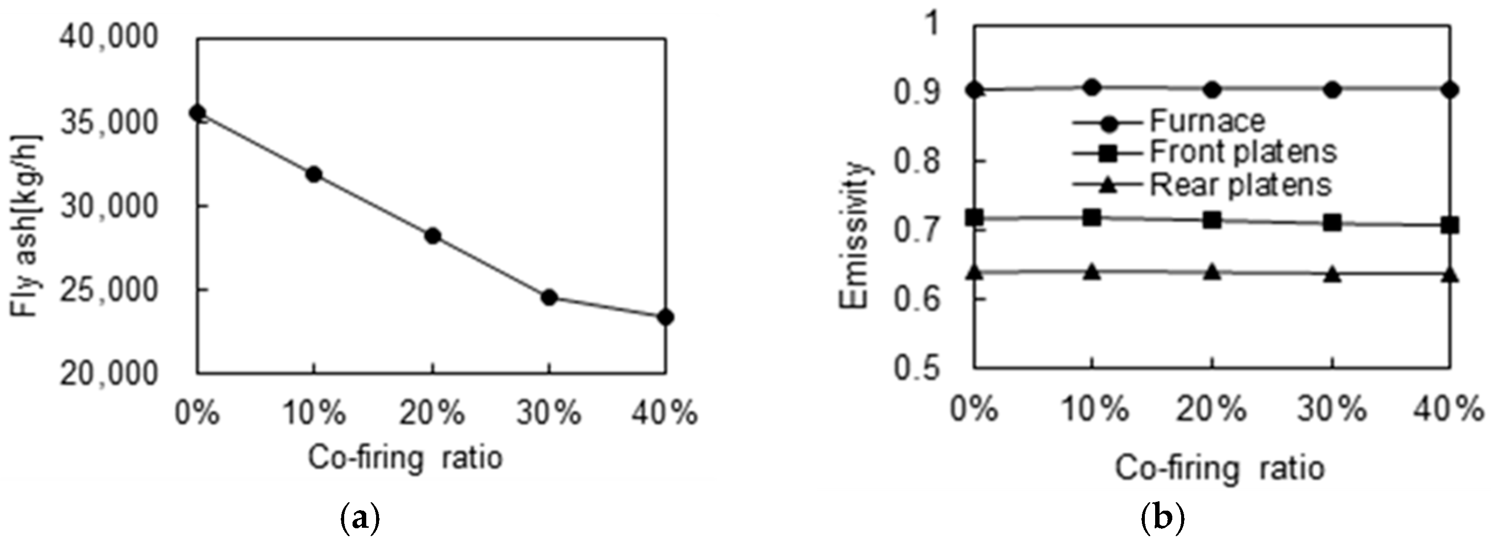
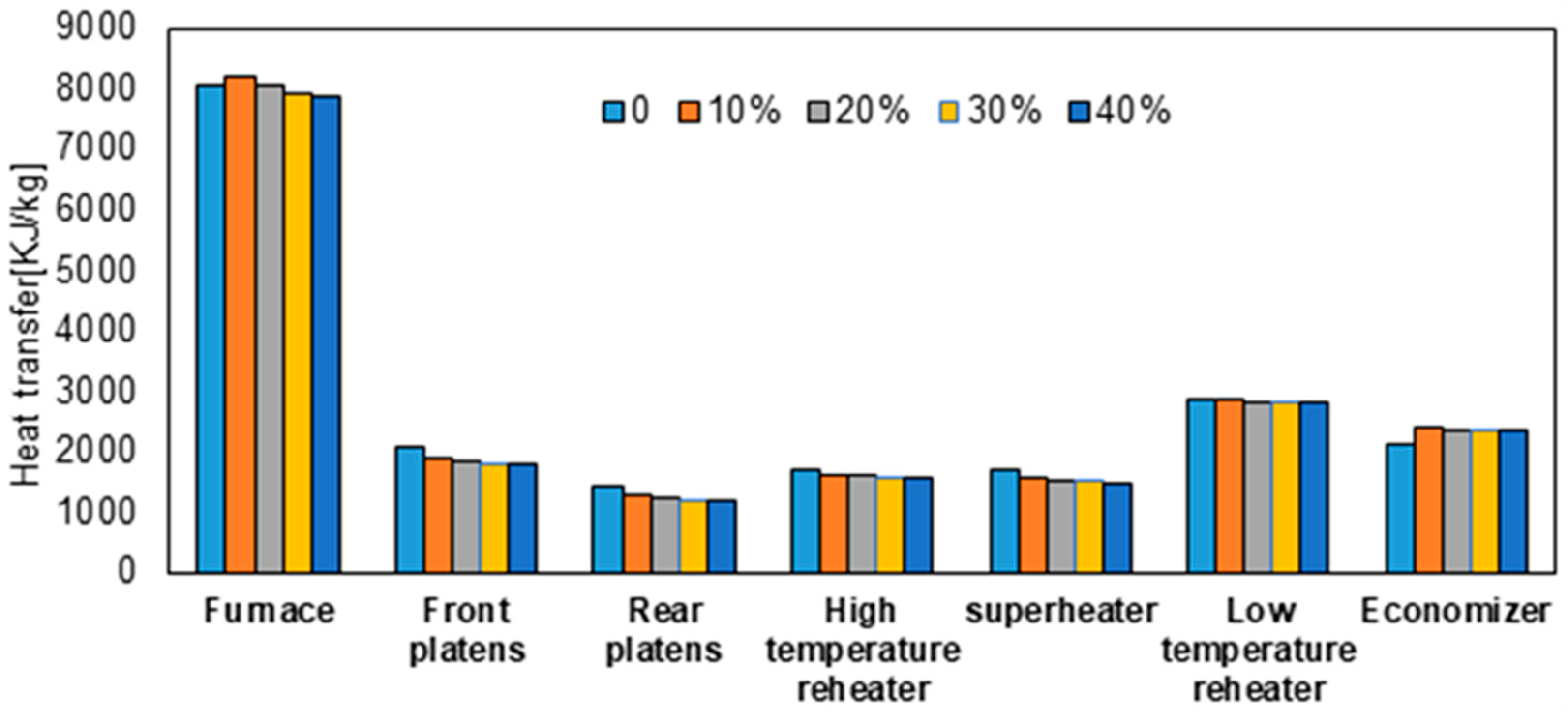
3.1.3. Heat Transfer Performance

The calculated heats transferred to the main heat exchangers of the boiler varying with the ammonia co-firing ratio are presented in Figure 7. As can be seen, the heat transferred to the furnace water walls increases a bit at the co-firing ratio of 10% and then decreases with the co-firing ratio increase. Such a trend is similar to the observation in a numerical simulation [26]. It is the result of the decrease in the flame temperature and the change in the flame emissivity caused by the variations of radiative components (ash particles, RO2 and H2O) in the flue gas. Along the flue gas flow, the heats transferred to the front and rear platen superheaters, high-temperature reheater, high-temperature superheater and low-temperature reheater decline with the increase in the co-firing ratio. Nevertheless, the extent of the declination generally decreases along the flue gas flow, as indicated by the greater extent of decrease for the front platen superheater and slight decrease for the low-temperature reheater. An exception is that the heat absorption by the economizer increases considerably when co-firing 10% ammonia relative to that of coal combustion, and then changes slightly at higher co-firing ratios.
As shown in Figure 7, ammonia co-firing does affect the heat transfer and heat distribution in the boiler and consequently the performance of the boiler. In a Benson-style supercritical boiler, the heat of superheated steam is absorbed mainly through the furnace water walls, various stages of superheaters and the economizer. Combining the heats from these exchangers, the heat of superheated steam slightly increases with increasing of the co-firing ratio. Nevertheless, the calculations revealed that the designed amount of the attempering water is sufficient to maintain the superheated steam temperature at the nominal value at the co-firing ratio up to 20% but slight over-temperatures occur at higher co-firing ratios. As for the reheated steam, its heat absorbed from the two stages of the reheaters decreases considerably with the co-firing ratio. It implies that the nominal reheated steam temperature may not be achievable with ammonia co-firing. To retain the nominal value, the burners have to be tilted up and/or the upper layers of the burners operated to increase the reheated steam temperature, as for the cases of 30% and 40% co-firing. Even so, the calculations indicated that the nominal reheated steam temperature could hardly be retained at co-firing ratios higher than 20%. Moreover, such boiler operations for adjusting the reheated steam temperature could further increase the superheated steam temperature. Additionally, if the boiler is operated at lower loads, while co-firing at higher ratios may maintain the superheated steam temperature, the under-temperature of the reheated steam would worsen further, which is likely to significantly degrade the performance of the boiler and power generation unit.

3.1.4. Boiler Thermal Efficiency

Figure 8 shows the boiler thermal efficiency varying with ammonia co-firing ratio. The calculated efficiency is based on the lower heating value of the input fuels. It is clear that the boiler thermal efficiency decreases nearly linearly from 93.7% of the sole coal combustion to 93.3% when increasing the co-firing ratio to 40%. The extent of the decrease at the co-firing ratio of 20% is generally consistent with that from the analysis on a 1000 MW boiler [11], but the efficiency further degrades at higher co-firing ratios.
It is well known that the biggest factor affecting the boiler efficiency is the heat loss through the exhausted flue gas from the boiler. As indicated in Figure 5d, the boiler exhausted flue gas temperature increases considerably with increasing of the co-firing ratio. Together with the increase in the flue gas volume, it causes efficiency loss of up to 0.7–0.8% at co-firing ratios of 30% and 40%. On the other hand, the heat loss due to the unburned carbon in ash and other losses associated with the ash obviously decline when increasing the co-firing ratio because the lower input of coal reduces the ash yield and consequently the ash-associated heat losses. The higher preheated air temperature due to the enhanced heating of the combustion air in the air preheater can enhance the combustion in the furnace, therefore offsetting the effect of the decreased flame temperature on coal combustion. Totally, the unburned carbon and other ash-related heat losses are reduced by 0.2–0.3% at co-firing ratios of 30% and 40%. Considering the effects of the co-firing on the heat losses, the calculated boiler thermal efficiency declines, but fortunately the extent is not so great even at higher co-firing ratios. Nevertheless, co-firing ammonia does cause the decrease in the boiler efficiency, as also observed in the evaluation of utility boilers [6,11]. It is one of the most influential aspects of ammonia co-firing affecting the boiler performance. The decrease in the boiler efficiency and difficulty in retaining reheated steam temperature suggest that optimized design and retrofit of the boiler are required so as to maintain the thermal efficiency and operation performance of the boiler for co-firing ammonia at higher ratios. For example, enlarging the area of the lower temperature heat exchanger surface before the economizer, i.e., the lower temperature reheater, may not only increase the heat absorption from the flue gas to increase the boiler efficiency but also help maintain the reheated steam temperature. It also implies that the impact of ammonia co-firing on the boiler performance to some extent depends on the designed structure of the boiler, in particular, the distribution of the heat adsorbed by the main heat exchangers. Such an issue is worthy of further investigation.

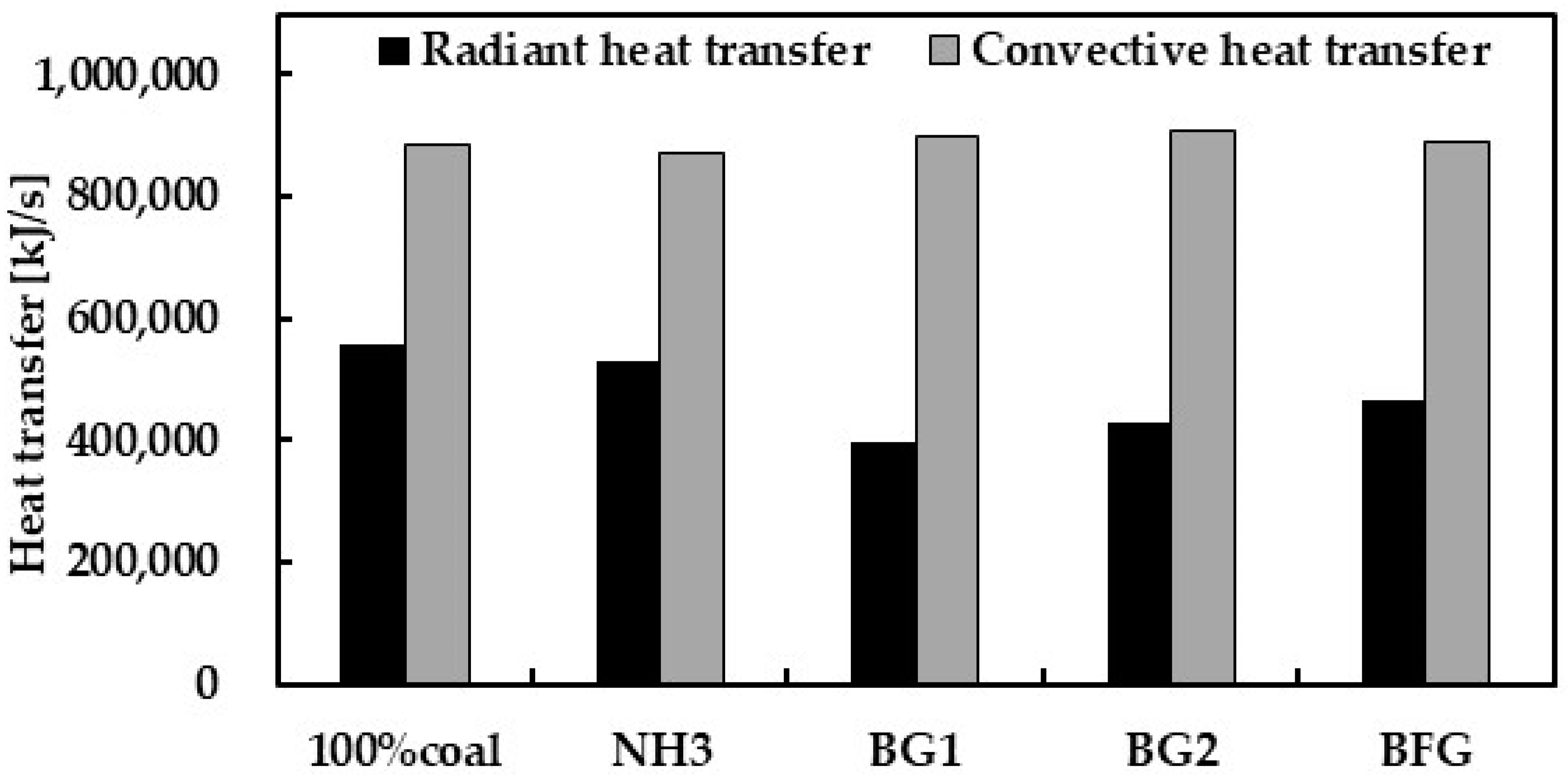
3.2. Comparison of Co-Firing Ammonia and Co-Firing Other Gaseous Fuels

While co-firing ammonia with coal is a newly developing technology, co-firing gaseous fuels including biomass gas and BFG is already applied for pulverized coal-fired boilers. In practice, the highest ratio of biomass gas co-firing is up to 25% [33] while the ratio of BFG co-firing could be up to 30% or even higher [32]. To further investigate the effect of ammonia co-firing, the performance of the boiler burning 20% ammonia was compared to that of co-firing two biomass gases (BG1 and BG2) and a BFG at the same ratio, based on thermal calculations. The calculated values of some performance parameters are provided in Table 4.
When co-firing biomass gases and BFG, the adiabatic flame temperature and furnace exit temperature are much lower than those when co-firing ammonia. It is clear that the biomass gases and BFG contain large fractions of inert gases (N2 as well as CO2 and H2O) and have much lower caloric values than ammonia (Table 3). Their co-firing at the same ratios of heat input produces much larger volumes of the flue gas and also causes greater changes in flue gas composition. As a consequence, co-firing results in much lower flame temperatures and also greatly decreases the radiation heats transferred to the furnace walls, as shown in Figure 9. Due to the significant increases in the flue gas volumes of co-firing the three low calorific value gases (Table 4), the convection heat transfer in the boiler is enhanced. It indicates that co-firing the three low calorific value gases significantly changes the heat distribution between radiation and convection in the boiler as compared to sole coal combustion and ammonia co-firing. Moreover, more heat is carried by the larger volume flue gas to the convection passes and also leads to the increased heat losses associated with the exhausted flue gas. Additionally, the significantly lower flame temperatures in the furnace (Table 4) deteriorate the combustion of pulverized coal, resulting in more heat losses of unburned carbon in ash. These determine significant decreases in the boiler efficiency (Table 4). For improving the heat transfer performance and also the boiler efficiency, the practical technology is to deliver the biomass gases and BFG through gas burners installed below the coal burner zone so as to increase the radiation heat absorbed by the furnace walls when retrofitting the existing boilers [32,33].
The comparisons in Table 4 and Figure 9 indicate that co-firing 20% ammonia provides a superior boiler performance over co-firing 20% biomass gases and BFG and one that is closer to sole pulverized coal firing. The distribution of the heat transfer in the furnace is relatively insignificantly affected and the boiler efficiency decreases slightly for co-firing 20% ammonia. It implies that, from the point view of heat transfer performance, the existing evaluated boiler can accommodate co-firing up to 20% ammonia without retrofits required for the heat exchangers. The retrofit of the combustion system may be required to maintain the combustion performance and particularly to control NOx emission, but ammonia can be injected into the furnace through the burner zone of the existing boiler. For co-firing ammonia at higher ratios, injecting more ammonia at the lower part of the burner zone or below the burner zone can improve the boiler performance following the experience of co-firing low calorific value gaseous fuels.

4. Conclusions

The performance of an existing 600 MW pulverized coal-fired utility boiler co-firing ammonia was evaluated by thermal calculation analysis. The evaluation covered a wide range of co-firing ratios up to 40% (on heat basis) to investigate the effect of the co-firing ratio on boiler heat transfer performance, aimed at developing higher ratio co-firing applications with the boiler performance comparable to sole coal combustion. The evaluations showed that, while co-firing up 20% ammonia in the existing boiler is feasible because the boiler performance is not considerably affected, the heat transfer performance of the boiler heat exchangers significantly changed at co-firing ratios of 30% and 40%. With increasing of the co-firing ratio from 0–40%, more heat transfer moves to the downstream of the flue gas flow, resulting in over-temperature of the superheated steam, under-temperature of the reheated steam and a decrease in boiler thermal efficiency at higher co-firing ratios. These imply boiler retrofits on the heat exchangers are required to accommodate a higher ratio of ammonia co-firing in the existing boiler for improving the performance, making it comparable to that of pulverized coal combustion. The boiler co-firing 20% ammonia was further compared with co-firing two biomass-produced gases and a BFG at the same ratio with the aim of exploring the application of existing gaseous fuel co-firing technologies for ammonia co-firing to improve boiler performance at higher co-firing ratios. The comparison indicated that co-firing ammonia presented superior performance over co-firing low calorific value gas fuels. Nevertheless, the technology of co-firing low calorific value gas fuels by injecting the gaseous fuel into the furnace at the lower part of, or below, the burner zone can be applied to achieve improved boiler performance in the existing boiler at higher co-firing ratios.

Author Contributions

Conceptualization, C.S. and S.W.; methodology, S.W. and C.S.; validation, S.W.; formal analysis, S.W.; resources, C.S.; writing—original draft preparation, S.W.; writing—review and editing, C.S. and S.W.; supervision, C.S. All authors have read and agreed to the published version of the manuscript.

Funding

This research received no external funding.

Data Availability Statement

Calculation data are available upon request.

Conflicts of Interest

The authors declare no conflict of interest.

Appendix A

Table A1. Heat exchange coefficients and ash thermal resistance of convective heat transfer surfaces.
Convection Heating Surfaceα1/W/m2·Kα2/W/m2·Kε
Front platens197.6048.450.718
Rear platens206.3157.50.640
High-temperature reheater172.4151.440.660
High-temperature superheater127.1171.010.636
Low-temperature reheater (vertical)141.8456.680.683
Low-temperature reheater (transverse)97.7165.990.687
Economizer90.7874.510.630

References

  1. Yanguas Parra, P.A.; Ganti, G.; Brecha, R.; Hare, B.; Schaeffer, M.; Fuentes, U. Global and Regional Coal Phase-Out Requirements of the Paris Agreement: Insights from the IPCC Special Report on 1.5 °C; Climate Analytics: Berlin, Germany, 2019. [Google Scholar]
  2. International Energy Agency. Phasing Out Unabated Coal—Current Status and Three Case Studies; Fernández, A.C., McNamara, K., Saive, G., Eds.; OECD Publishing: Paris, France, 2021.
  3. Global Energy Interconnection Development and Cooperation Organization. China’s Carbon Peak Research Report before 2030. Available online: https://news.bjx.com.cn/html/20210319/1142856.shtml (accessed on 6 March 2023).
  4. Xu, Y.; Yang, K.; Zhou, J.; Zhao, G. Coal-biomass co-firing power generation technology: Current status, challenges and policy implications. Sustainability 2020, 12, 3692. [Google Scholar] [CrossRef]
  5. Zhang, X.; Meloni, S. Technology Developments in the Co-Firing of Biomass. IEA Clean Coal Centre, 26 August 2020. Available online: https://www.sustainable-carbon.org/report/technology-developments-in-cofiring-biomass-ccc-305/ (accessed on 6 March 2023).
  6. Xu, Y.; Wang, H.; Liu, X.; Zhu, J.; Xu, J.; Xu, M. Mitigating CO2 emission in pulverized coal-fired power plant via co-firing ammonia: A simulation study of flue gas streams and exergy efficiency. Energy Convers. Manag. 2022, 256, 115328. [Google Scholar] [CrossRef]
  7. International Energy Agency. The Role of Low-Carbon Fuels in the Clean Energy Transitions of the Power Sector; OECD Publishing: Paris, France, 2021.
  8. Lee, H.; Lee, M.J. Recent advances in ammonia combustion technology in thermal power generation system for carbon emission reduction. Energies 2021, 14, 5604. [Google Scholar] [CrossRef]
  9. Kobayashi, H.; Hayakawa, A.; Somarathne, K.D.; Okafor, E.C. Science and technology of ammonia combustion. Proc. Combust. Inst. 2019, 37, 109–133. [Google Scholar] [CrossRef]
  10. Valera, M.A.; Amer, H.F.; Azad, A.K.; Dedoussi, I.C.; Joannon, M.; Fernandes, R.X.; Glarborg, P.; Hashemi, H.; He, X.; Mashruk, S.; et al. Review on ammonia as a potential fuel: From synthesis to economics. Energy Fuels 2021, 35, 6964–7029. [Google Scholar] [CrossRef]
  11. Genichiro, N.; Hiroki, I.; Takamasa, I.; Emi, O.; Yoshitomo, O. Development of co-firing method of pulverized coal and ammonia to reduce greenhouse gas emissions. IHI Eng. Rev. 2020, 53, 1–10. Available online: https://www.ihi.co.jp/ihi/technology/review_library/review_en/2020/_cms_conf01/__icsFiles/afieldfile/2021/01/14/Vol53No1_F.pdf (accessed on 8 March 2023).
  12. Tamura, M.; Gotou, T.; Ishii, H.; Riechelmann, D. Experimental investigation of ammonia combustion in a bench scale 1.2 MW-thermal pulverised coal firing furnace. Appl. Energy 2020, 277, 115580. [Google Scholar] [CrossRef]
  13. Wang, X.; Fan, W.; Chen, J.; Feng, G.; Zhang, X. Experimental study and kinetic analysis of the impact of ammonia co-firing ratio on products formation characteristics in ammonia/coal co-firing process. Fuel 2022, 329, 125496. [Google Scholar] [CrossRef]
  14. Chen, P.; Wang, H.; Jiang, B.; Wang, Y.; Gu, M.; Chen, G. An experimental and theoretical study of NO heterogeneous reduction in the reduction zone of ammonia co-firing in a coal-fired boiler: Influence of CO. Fuel Process. Technol. 2022, 231, 107184. [Google Scholar] [CrossRef]
  15. Taniguchi, M. Flame propagation velocity for co-combustion of pulverized coals and gas fuels. Energy Fuels 2021, 35, 6305–6314. [Google Scholar] [CrossRef]
  16. Xia, Y.; Hadi, K.; Hashimoto, G.; Hashimoto, N.; Fujita, O. Effect of ammonia/oxygen/nitrogen equivalence ratio on spherical turbulent flame propagation of pulverized coal/ammonia co-combustion. Proc. Combust. Inst. 2021, 38, 4043–4052. [Google Scholar] [CrossRef]
  17. Hadi, K.; Ichimura, R.; Hashimoto, G.; Xia, Y.; Hashimoto, N.; Fujita, O. Effect of fuel ratio of coal on the turbulent flame speed of ammonia/coal particle cloud co-combustion at atmospheric pressure. Proc. Combust. Inst. 2021, 38, 4131–4139. [Google Scholar] [CrossRef]
  18. Zhu, J.; Liu, X.; Xu, Y.; Xu, J.; Wang, H.; Zhang, K.; Cheng, X.; Yu, D. Probing into volatile combustion flame and particulate formation behavior during the coal and ammonia co-firing process. Energy Fuels 2022, 36, 9347–9356. [Google Scholar] [CrossRef]
  19. Takatoshi, Y.; Takeshi, A.; Yuichiro, U.; Tadashi, S.; Teruyuki, O.; Akimasa, T. Development of Ammonia Co-firing Technology for Coal-fired Boilers toward Decarbonized Society. Mitsubishi Heavy Ind. Tech. Rev. 2022, 59. Available online: https://www.mhi.co.jp/technology/review/pdf/e594/e594060.pdf (accessed on 7 March 2023).
  20. Tan, J.X.; He, Y.; Zhu, R.; Zhu, Y.; Wang, Z. Experimental study on co-firing characteristics of ammonia with pulverized coal in a staged combustion drop tube furnace. Proc. Combust. Inst. 2022, in press. [Google Scholar] [CrossRef]
  21. Tanigawa, H. Test results of the ammonia mixed combustion at Mizushima power station unit No. 2 and related patent applications. In Proceedings of the 2018 AIChE Annual Meeting, Pittsburgh, PA, USA, 31 October 2018. [Google Scholar]
  22. Yoshizaki, T. Test of the Co-firing of Ammonia and Coal at Mizushima Power Station. In CO2 Free Ammonia as an Energy Carrier, 1st ed.; Ken-ichi, A., Hideaki, K., Eds.; Springer: Singapore, 2022; pp. 601–611. [Google Scholar]
  23. Bai, H.; Zhang, Z.; Li, Z.; Wu, X.; Guo, X.; Zhang, J.; Bi, D. Industrial Experiment on NOx Reduction by Urea Solution Injection in the Fuel-Rich Zone of a 330 MW Tangentially Pulverized Coal-Fired Boiler. ACS Omega 2022, 7, 11853–11861. [Google Scholar] [CrossRef]
  24. Hiroki, I.; Emi, O.; Takahiro, K.; Takamasa, I.; Toshiro, F. Development of co-firing technology of pulverized coal and ammonia for suppressing the NOx generation. Trans. JSME 2020, 86, 19–00363. [Google Scholar] [CrossRef] [Green Version]
  25. Niu, T.; Zhang, W.; Liu, X.; Hu, D.; Wang, T.; Xie, Y.; Wang, H. Industrial-scale experimental investigation of ammonia-coal cofiring in coal-fired boiler. Clean Coal Technol. 2022, 28, 193–200. [Google Scholar] [CrossRef]
  26. Zhang, J.; Ito, T.; Ishii, H.; Ishihara, S.; Fujimori, T. Numerical investigation on ammonia co-firing in a pulverized coal combustion facility: Effect of ammonia co-firing ratio. Fuel 2020, 267, 117166. [Google Scholar] [CrossRef]
  27. Ishihara, S.; Zhang, J.; Ito, T. Numerical calculation with detailed chemistry of effect of ammonia co-firing on NO emissions in a coal-fired boiler. Fuel 2020, 266, 116924. [Google Scholar] [CrossRef]
  28. Ishihara, S.; Zhang, J.; Ito, T. Numerical calculation with detailed chemistry on ammonia co-firing in a coal-fired boiler: Effect of ammonia co-firing ratio on NO emissions. Fuel 2020, 274, 117742. [Google Scholar] [CrossRef]
  29. Design Department of Beijing Boiler Plant. Standard Method for Calculating the Thermal Power of Boiler Units, 1st ed.; Machinery Industry Press: Beijing, China, 1976; pp. 29–37. [Google Scholar]
  30. Max, A. Ammonia: Principles and Industrial Practice, 1st ed.; WILEY-VCH: New York, NY, USA, 1999; pp. 9–12. [Google Scholar]
  31. Wang, Y.; Deng, L.; Chang, G.; Liu, H.; Lyu, K.; Nie, X.; Zhang, G. Influence of biomass gas parameters on coupled coal-fired biomass generation. Therm. Power Gener. 2021, 50, 35–40. (In Chinese) [Google Scholar] [CrossRef]
  32. Wang, C.; Wei, J.; Huang, J. Thermodynamic characteristics and economic analysis of a BFG /pulverized coal mixed combustion boiler. J. Chin. Soc. Power Eng. 2012, 32, 517–522. (In Chinese) [Google Scholar]
  33. Bolhar-Nordenkampf, M.; Isaksson, J. Operating experiences of large scale CFB-gasification plants for the substitution of fossil fuels. In Proceedings of the 24th European Biomass Conference and Exhibition, Amsterdam, The Netherlands, 6–9 June 2016; pp. 375–381. [Google Scholar] [CrossRef]
Figure 1. Schematic of the overall layout of the 600 MW supercritical boiler.
Energies 16 02773 g001
Figure 2. Volumetric flow rates of combustion air and flue gas.
Energies 16 02773 g002
Figure 3. Flue gas composition (a) and CO2 emission (b) varying with ammonia co-firing ratio.
Energies 16 02773 g003
Figure 4. Variations of (a) fly ash content and (b) flue gas emissivity with the co-firing ratio.
Energies 16 02773 g004
Figure 5. Effect of ammonia co-firing on the gas temperatures in the boiler, (a) adiabatic flame temperature and flue gas temperatures at (b) furnace exit, (c) economizer outlet and (d) boiler exit.
Energies 16 02773 g005
Figure 6. Effect of ammonia co-firing on (a) sulfuric acid dew point and (b) water vapor dew point.
Energies 16 02773 g006
Figure 7. Effect of co-firing on heat transfer in boiler furnace and to heat exchangers.
Energies 16 02773 g007
Figure 8. Effect of ammonia co-firing on boiler thermal efficiency.
Energies 16 02773 g008
Figure 9. Comparing the distribution of heat transfer in the boiler between co-firing ammonia and co-firing three low caloric value gases at co-firing ratio of 20%.
Energies 16 02773 g009
Table 1. Fired coal properties.
Proximate Analysis/wt%Ultimate Analysis/wt%Qnet/kJ/kg
MoistureAshVolatilesFixed CarbonCHONS
13.0015.0024.2247.7857.333.629.940.700.4121,805
The values are on an as-received basis.
Table 2. Designed thermal parameters of the boiler.
ParameterValue
Superheated steam rate/t/h1913
Superheated steam pressure/MPa25.4
Superheated steam temperature/°C571
Reheated steam rate/t/h1586
Reheated steam inlet pressure/MPa4.35
Reheated steam inlet temperature/°C310
Reheated steam outlet pressure/MPa4.16
Reheated steam outlet temperature/°C569
Feed water temperature/°C282
Ambient temperature/°C20
Flue gas exit temperature/°C126
Table 3. The properties of two biomass-produced gases and a BFG.
ItemCO/%H2/%CH4/%C2H4/%CO2/%N2/%H2O/%Qnet/kJ/m3
Biomass gas 112.4014.103.901.8016.3037.9013.605682
Biomass gas 219.1510.131.0305.9543.0820.663880
BFG24.002.300.90015.6057.2003632
Table 4. Some performance parameters of co-firing different gaseous fuels at the ratio of 20%.
ItemAdiabatic Flame Temperature/°CFurnace Exit Temperature/°CBoiler Thermal
Efficiency/%
Total Flue
Gas/m3/s
100% coal1969138093.7434.5
NH31946132093.5453.7
BG11534106989.9760.2
BG21568109387.9788.4
BFG1696112790.3659.1
Disclaimer/Publisher’s Note: The statements, opinions and data contained in all publications are solely those of the individual author(s) and contributor(s) and not of MDPI and/or the editor(s). MDPI and/or the editor(s) disclaim responsibility for any injury to people or property resulting from any ideas, methods, instructions or products referred to in the content.

