Article

Heat Transfer Augmentation and Entropy Generation Analysis of Microchannel Heat Sink (MCHS) with Symmetrical Ogive-Shaped Ribs

1
Department of Mechanical Engineering, University of Engineering and Technology, Peshawar 25000, Pakistan
2
Department of Mechanical Engineering, School of Mechanical and Manufacturing Engineering (SMME), National University of Sciences and Technology (NUST), Islamabad 44000, Pakistan
3
Department of Aerospace Engineering, Khalifa University of Science and Technology (KUST), Abu Dhabi 127788, United Arab Emirates
4
Department of Mechanical Engineering, Aerospace and Aviation Campus, Air University Islamabad, Kamra, Islamabad 44000, Pakistan
5
School of Engineering, Edith Cowan University, Joondalup, WA 6027, Australia
*
Author to whom correspondence should be addressed.
Energies 2023, 16(6), 2783; https://doi.org/10.3390/en16062783
Submission received: 10 February 2023 / Revised: 8 March 2023 / Accepted: 13 March 2023 / Published: 17 March 2023
(This article belongs to the Section J1: Heat and Mass Transfer)

Abstract

:
This study proposes the use of symmetrical ogive-shaped ribs on the walls of microchannel heat sinks (MCHS) to improve their thermal performance with minimal pressure drop. The ribs are arranged in three different configurations: ribs attached to all channel walls (MC-SAWR), ribs attached to side channel walls (MC-SSWR), and ribs attached to the bottom channel wall (MC-SBWR). Numerical investigations are conducted using the laminar conjugate heat transfer model to study the flow and heat transfer characteristics of the MCHS. The augmentation entropy generation number and thermal enhancement factor criterion are used to quantify the overall hydrothermal performance of the MCHS. The results show that the inclusion of symmetrical ogive-shaped ribs improves the Nusselt number of MCHS. The MC-SAWR configuration shows the highest Nusselt number improvement of 13–50% compared to the smooth MCHS over the Reynolds number range of 100–1000. Additionally, the MC-SAWR configuration shows a maximum reduction of 58% in the total entropy generation rate as it has the smallest augmentation entropy generation number value of 0.42. In terms of the thermal enhancement factor criterion, the MC-SSWR configuration shows the highest performance at Reynolds numbers below 400, but the MC-SAWR configuration outperformed the MC-SSWR configuration at Reynolds numbers above 400. Therefore, the MC-SAWR configuration is the best configuration that provides high cooling performance.

1. Introduction

As electronic systems continue to advance and become more compact, traditional air-cooling technologies are lagging in fulfilling their heat removal requirements. Microchannel heat sinks (MCHS) were first presented in 1981 by Tuckerman and Pease [1] as an alternative to conventional cooling techniques. These heat sinks solved the problem of heat flux removal as they dissipate heat up to 790 W/cm2. However, the basic design of a smooth channel MCHS is insufficient to keep up with the high cooling requirements of modern compact electronics. Since then, researchers have studied various passive and active techniques to enhance heat removal in MCHS.
Most of the research has focused on enhancing the thermal performance of MCHS by applying passive methods that include altering the channel geometry and modifying the wall surfaces, such as adding ribs, cavities, protrusions, dimples, grooves, etc., which generate flow disruptions [2,3]. There has been considerable interest in adding cavities and ribs on smooth rectangular MCHS walls because they improve heat transfer by forming recirculation zones that decrease local thermal resistance near the walls. These passive techniques have proven to be effective in providing a better cooling solution for modern compact electronics [4].
Wang et al. [5] analyzed the impact of varying the geometrical parameters of cavities and ribs on heat transfer characteristics using numerical and experimental methods. They discovered that increasing the height of ribs enhances the Nusselt number of rib-grooved MCHS. However, they found that the improvement in heat transfer was insufficient to overcome the pressure drop, and the thermal enhancement factor was less than one. Ahmad et al. [6] conducted numerical analysis of MCHS with cylindrical fins and cavities and found that cylindrical-shaped cavities and fins significantly improve MCHS thermal performance. However, such configurations can lead to a significant increase in pressure losses. Khan et al. [7] numerically investigated various rib configurations in MCHS with fixed rib length and width in the Reynolds number range of 100 to 500. Ghani et al. [8] examined the effects of combining rectangular profile ribs with sinusoidal cavities and found that sinusoidal cavities reduce pressure drop by increasing the flow area, while rectangular ribs enhance heat removal by increasing the surface area for heat dissipation and generating turbulence in the flow. Li et al. [9] conducted numerical irreversibility analysis for MCHS with a combination of triangular cavities and rectangular ribs and found that the addition of ribs and cavities inside the MCHS improves heat dissipation by reducing the irreversibilities associated with heat transfer.
Zhai et al. [10] conducted numerical simulations on various arrangements of cavities and ribs in MCHS and found that the combination of triangular cavities and ribs yields a better heat transfer rate at Re ranging from 300 to 600. In a separate study, Zhai et al. [11] utilized entropy generation and field synergy principles to investigate the effect of various rib structures with fan-shaped re-entrant cavities. They demonstrated that including ribs improves heat transfer by enhancing the synergetic relationship between the velocity and temperature fields. Li et al. [12] conducted numerical investigations on the effects of pin-fins and dimples on MCHS performance, studying the impact of geometrical parameters such as dimple depth, fin diameter, and stream-wise spacing. According to their findings, using larger diameter fins with decreasing stream-wise pitch leads to an improvement in the Nusselt number ratio (Nu/N u 0 ). Rehman et al. [13] utilized the same technique by incorporating hemispherical-shaped dimples and protrusions inside the MCHS. They found that adding dimples/protrusions enhances heat transfer due to improved fluid inter-mixing. In another study, Rehman et al. [14] utilized irreversibility and exergy analysis to compare the performance of MCHS with different rib geometries and found that hydrofoil-shaped ribs transfer heat with the least amount of irreversibility.
Many researchers have shown that adding surface enhancers such as ribs, cavities, fins, and dimples can improve heat dissipation, but this improvement comes at the cost of pressure losses since these structures induce secondary flow, vortices, and other disturbances. Several studies have focused on reducing these pressure losses. For example, Ahmad et al. [15] developed a method for refining the rib profile geometry and concluded that chamfering the rib with the base of MCHS at a 45° angle can significantly improve performance while also reducing pressure losses without affecting heat transfer. In contrast, Li et al. [16] reported that ribs have a greater influence on MCHS performance than cavities. Although both have been integrated into the MCHS to improve heat transfer, the thermal boundary layer thickness for cavities is greater than for ribs, meaning that cavities do not greatly improve heat transfer. Xia et al. [17] examined the performance of MCHS with triangular re-entrant cavities and discovered that the formation of vortices can significantly improve fluid mixing. They showed that complex geometry improves heat transfer not only due to vortex formation but also due to boundary layer interruption. A recent study by Ahmed et al. [18] investigated MCHS performance by inserting four types of ribs into the channel’s sidewalls. The study found that connecting these ribs can enhance the efficiency of MCHS, and hydrofoil ribs outperform elliptical ribs in terms of hydrodynamics and thermal efficiency. The effect of trefoil rib configurations on heat transfer and flow characteristics in MCHS were numerically examined and they found that the MC-SWTR configuration performs best with the trefoil ribs mounted on the opposite side wall [19,20]. Shazad et al. [21] examined the effect of staggered and aligned configurations of NACA 2412 hydrofoil-shaped ribs on the hydraulic-thermal characteristics of MCHS and discovered that the staggered configuration provides the best overall performance.
The previous literature indicates that although modifications in the form of different shaped ribs, cavities, fins, and dimples improve the thermal performance of MCHS, they also increase pressure drop, leading to higher pumping power requirements. This study proposes the use of symmetrical ogive-shaped ribs to enhance the thermal performance of MCHS with minimal pressure drop. The study utilizes a novel method of combining two opposite-facing ogive-shaped ribs to create symmetrical ogive ribs, which reduce pressure drop by eliminating flow separation on the downside of the step or ogive-shaped rib. While the use of ogive-shaped geometry for heat transfer enhancement has not been explored extensively, this study aims to investigate the hydro-thermal characteristics of MCHS when symmetrical ogive-shaped ribs are attached parallel to the bottom (MC-SBWR), side (MC-SSWR), and all walls (MC-SAWR) of the MCHS channel. The use of symmetrical ogive-shaped ribs for heat transfer improvement in MCHS is a unique aspect of this study. The impact of symmetrical ogive ribs on the performance of MCHS has been quantified based on parameters such as Nusselt number (Nu), thermal enhancement factor ), pressure drop (Δp), thermal resistance ( R t h ), pumping power, entropy generation rate ( S ˙ g e n ), augmentation entropy generation number ( N s ), and thermal transport efficiency ( η t ).

2. Materials and Methods

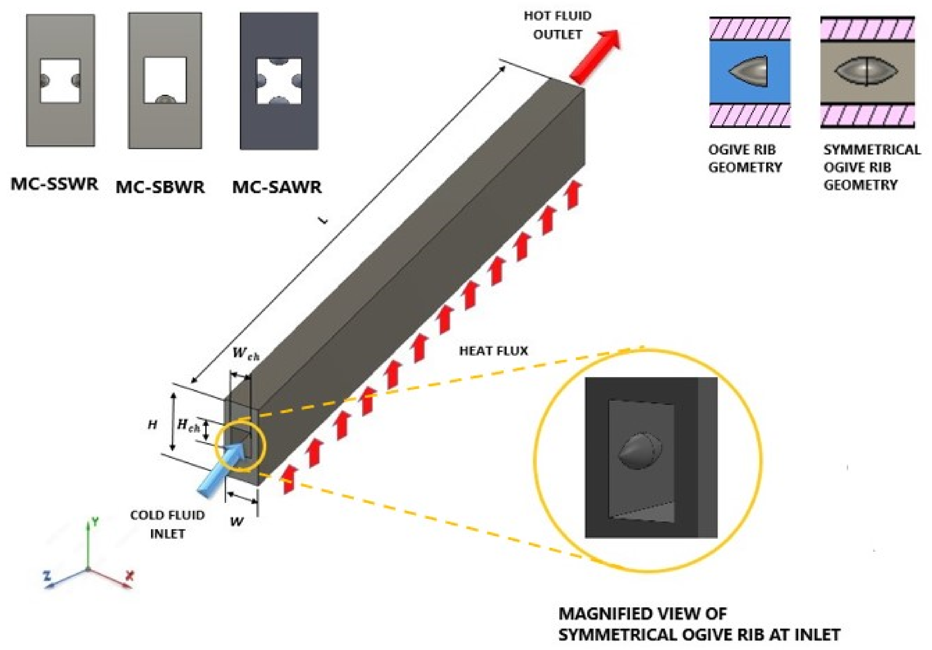
2.1. Physical Model Description

The rectangular microchannel has the least thermal resistance compared to the triangular and trapezoidal microchannels [6]. Hence, a rectangular-shaped microchannel is considered in the present study. Figure 1 shows the computational domain, which has external dimensions of L = 10 mm, W = 0.6 mm, and H = 1.5 mm. The fluid domain has dimensions of W c h = 0.35 mm and H c h = 0.5 mm. In MC-SAWR configuration, twelve symmetrical ogive ribs are attached on each channel wall with a spacing of 0.4 mm between them. Similarly, in MC-SSWR configuration, symmetrical ogive ribs are mounted on both side walls, and in MC-SBWR they are mounted only on the bottom wall. Water (coolant) enters the computational domain at the inlet with various velocity values corresponding to the Re range of 100–1000. Constant heat flux is applied at the base of the computational domain. All walls exposed to the surrounding, except the base, are considered perfectly adiabatic (insulated). Copper is used as the material for MCHS due to its high thermal conductivity, whereas water (liquid) is used as a coolant due to its high specific heat capacity. Constant thermo-physical property values are assumed for copper and water as listed in Table 1.
An ogive shape is a two-dimensional or three-dimensional object with a round tapered end [22]. The ogive shape is formed by rotating the tangent ogive profile shown in Figure 2 around the circle base. The equation for the tangent ogive shape profile used for modeling of ogive rib shape is given by [22].
y = ρ o r 2 L o r 2     D o r   C 2 1 4
L o r is the ogive overall length = 0.2 mm, D o r is ogive base diameter = 0.1 mm, c is L o r / D o r = 2, which refers to the sharpness of the ogive shape. The ogive equation defines the shape of an ogive in two dimensions. In this formulation, ρ o r represents the radius of the circle which is related to the radius of ogive (R) and the length of the ogive L o r [23]. The ρ o r chosen for the ogive profile in this study is 0.3 mm.

2.2. Governing Equations

In the present study, the no-slip boundary condition is assumed, and the flow is considered to be in a laminar and steady-state condition. Heat transfer is also considered in a steady-state condition. However, the effects of gravitational force, body force, viscous dissipation, and radiation mode of heat transfer are not taken into account in this study.
For an incompressible fluid, the equations of continuity and momentum balance are given as [6]:
· U   =   0
ρ f U ·   U = p +   μ f 2 U
The energy equation for the fluid and the solid domain is given as [6]:
For fluid:
ρ f c p f U · T f   =   k f · T f
For solid:
( k s   · T s ) = 0
The finite volume method is used to discretize the above governing equations across solid and fluid computational domains into finite volumes by using commercially available ANSYS Fluent 19.2 code. Second upwind interpolation is used to determine momentum, energy, and continuity equations with diffusive and convective components. The pressure–velocity coupling was implemented using the SIMPLE algorithm. The numerical solution is deemed complete when the momentum and continuity equations, as well as the energy equation, are reduced to 10 6 .
To solve the governing equations mentioned above, we consider the following boundary conditions listed in Table 2.

2.3. Data Deduction

The equation for Reynolds number (Re) is given as [14]:
R e = ρ f u m D h μ f
Hydraulic diameter for rectangular cross-section is calculated by [14]:
D h = 2 H c h W c h H c h + W c h
The friction factor is calculated by using Darcy–Weisbach equation [14]:
f = 2 D h Δ p L c h ρ f w m 2
The average heat transfer coefficient is given by [14]:
h = q w A b 2 W c h + H c h L c h Δ T
where q w is heat flux applied to the base and the area of the base is represented by A b ,while the temperature difference Δ T is given by.
Δ T = T w T f
The average channel wall temperature is calculated as [14]:
T w = T w x , y d y d x d y d x
Average base wall temperature ( T b ) and bulk fluid temperature ( T f ) are calculated as follows [14]:
T b = T b x , y d y d x d y d x
T f = T f i , x ρ f i , x   v · d A d x ρ f i , x   v · d A d x
The total thermal resistance for MCHS is calculated as [14].
R t h = R c o n d + R c o n v + R c a p
R t h = T b T w q w A b + T w T f q w A b + T f T i n q w A b = T b T i n q w A b
Nusselt number ratio shows the improvement in the heat transfer coefficient of smooth MCHS with the addition of ogive rib configurations.
N u a v g N u o   a v g = h a v g h o   a v g
where N u o   a v g is the average Nusselt number of smooth MCHS, while N u a v g donates average Nusselt number for MCHS with configurations of ogive ribs.
Irreversibility analysis of MCHS is performed by finding the entropy generation rates S ˙ g e n [14].
S ˙ g e n = S ˙ g e n , Δ T + S ˙ g e n , Δ P
Irreversibility due to heat transfer is found by calculating the entropy generation rate due to heat transfer ( S ˙ g e n , Δ T ) [14].
S ˙ g e n , Δ T = Ω S ˙ g e n , Δ T = q w A b a s e T W T f T f T W
Irreversibility due to pressure drop is found by calculating the entropy generation rate due to pressure drop ( S ˙ g e n , Δ p ) [14].
S ˙ g e n , Δ p = Ω S ˙ g e n , Δ p d V = m ˙ ρ f T f Δ p
Bejan number is used to calculate the ratio between thermal and total losses [14].
B e = S ˙ g e n , Δ T S ˙ g e n
The augmentation entropy generation number ( N s ) is utilized to compare entropy generation in MCHS with symmetrical ogive rib configurations and a smooth channel [14].
N s = S ˙ g e n S ˙ g e n , 0
Thermal transport efficiency is calculated as [14]:
η t = 1 Q ˙ d Q ˙
where Q ˙ d is irreversible heat loss while Q ˙ represents input heat load.
Q ˙ d = Ω k f T f 2 T f d V
The pumping power requirement is calculated as:
Pp = p   i n A i n u i n
where p i n is the pressure of coolant at the inlet, A i n is the area of inlet cross-section, and u i n is inlet velocity.
The overall performance of microchannel with configurations of symmetrical ogive ribs is quantified by calculating the thermal enhancement factor that gives the ratio of improvement in heat transfer against the increase in pressure losses [14].
η = N u N u 0 f f 0 3

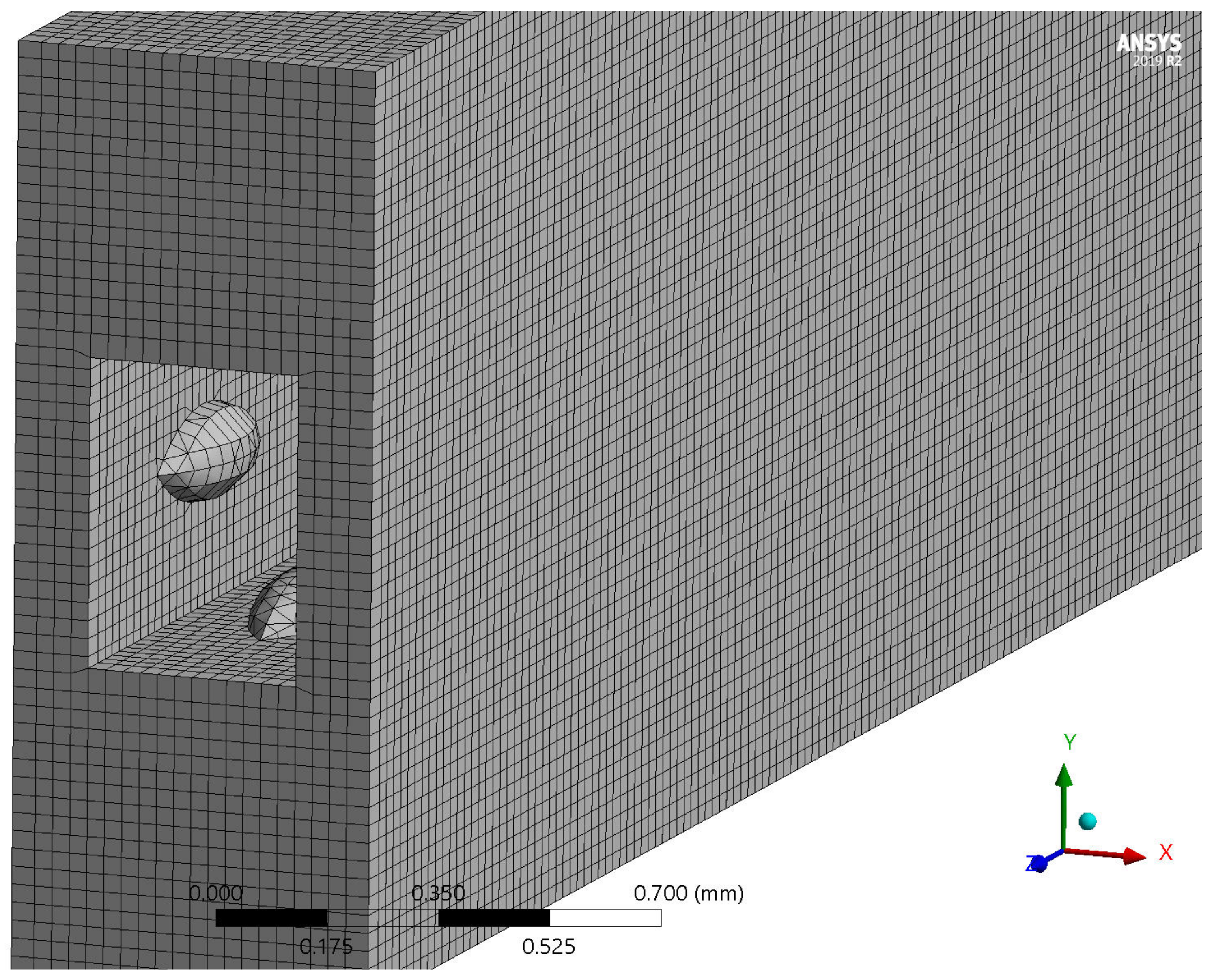
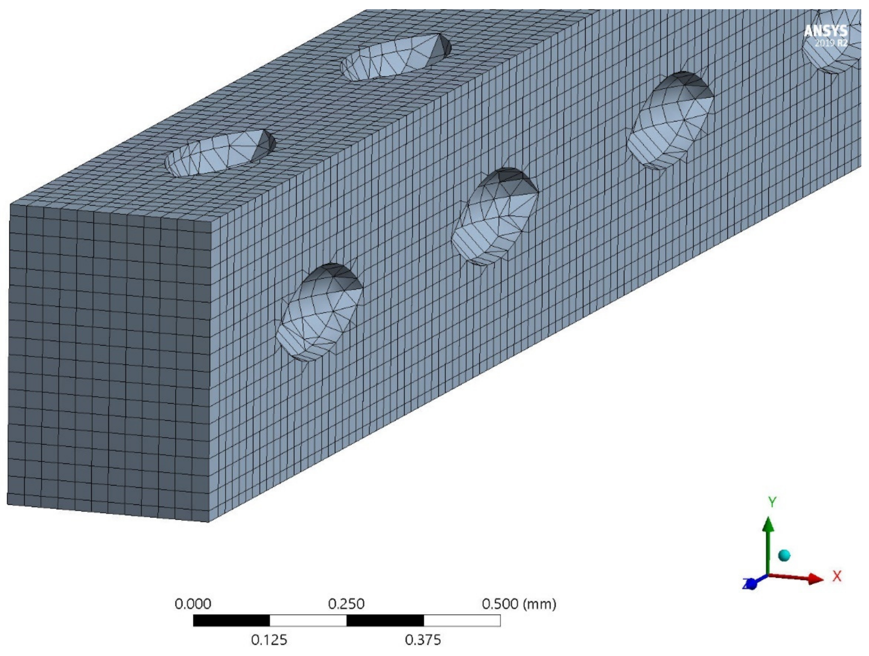
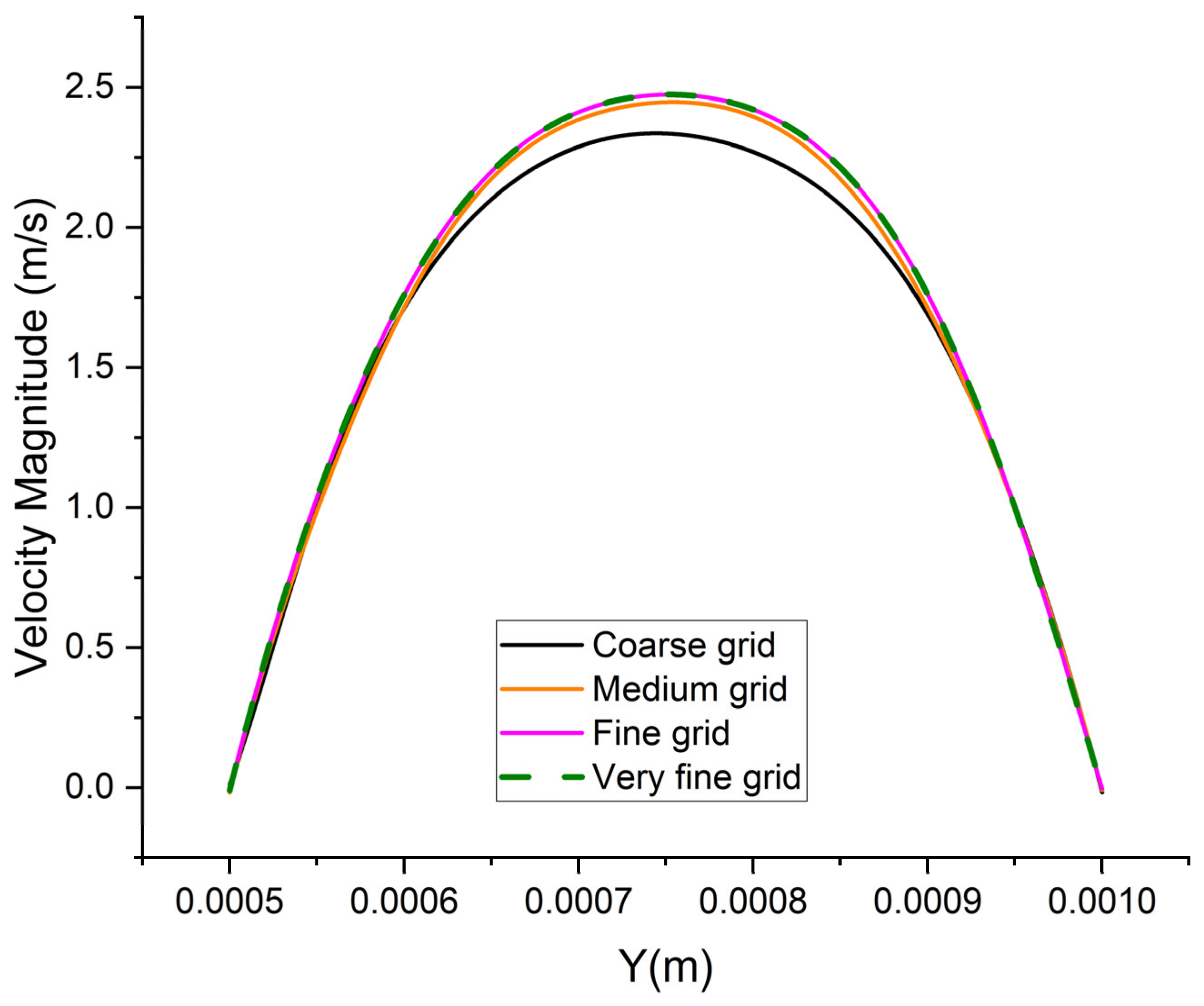
2.4. Grid Independent Study

A mesh is generated to divide the solid and fluid computational domains into finite elements, as illustrated in Figure 3 and Figure 4. The grid’s orthogonal quality and skewness are set to acceptable levels to ensure the accuracy of numerical simulations. To determine the optimal number of grid elements that would ensure accurate results at a low computational cost, a grid-independent study is carried out for the MCHS computational domain, as shown in Table 3. For the grid independence study, the velocity profile is plotted for MCHS computational domains of varying grid sizes along the channel height, as shown in Figure 5. The results indicate that the velocity profiles obtained for a fine grid (810,563 elements) and a very fine grid (1,058,252 elements) superimpose on each other. This suggests that increasing the grid size beyond 810,563 elements has no significant impact on the results, and the simulation results become independent of grid size. Therefore, a grid size of 0.8 million is selected for all considered MCHS configurations to achieve a reasonable trade-off between computing time and accuracy.

3. Results and Discussion

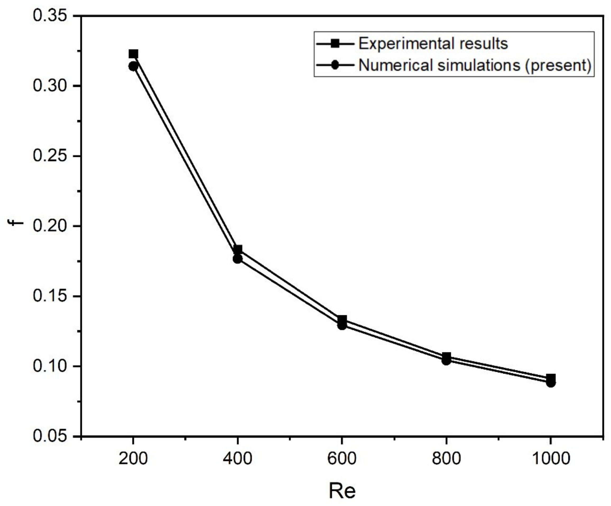
3.1. Results Validation

To validate the model, numerical results for both smooth and ribbed MCHS were compared to experimental results performed by Wang et al. [5]. The operating and geometrical conditions used in the numerical simulations are precisely the same as those used in the experiments conducted by Wang et al. [5]. For the smooth MCHS, Figure 6 and Figure 7 compare the Nusselt number (Nu) and friction factor (f) to the experimental results. Similarly, Figure 8 and Figure 9 compare the Nusselt number (Nu) and friction factor (f) for ribbed MCHS with the experimental results of Wang et al. [5]. For both smooth and ribbed MCHS, a maximum deviation of 8% was found between the experimental and numerical results. Therefore, the current numerical model is valid for investigating the thermal and hydraulic characteristics of MCHS numerically.

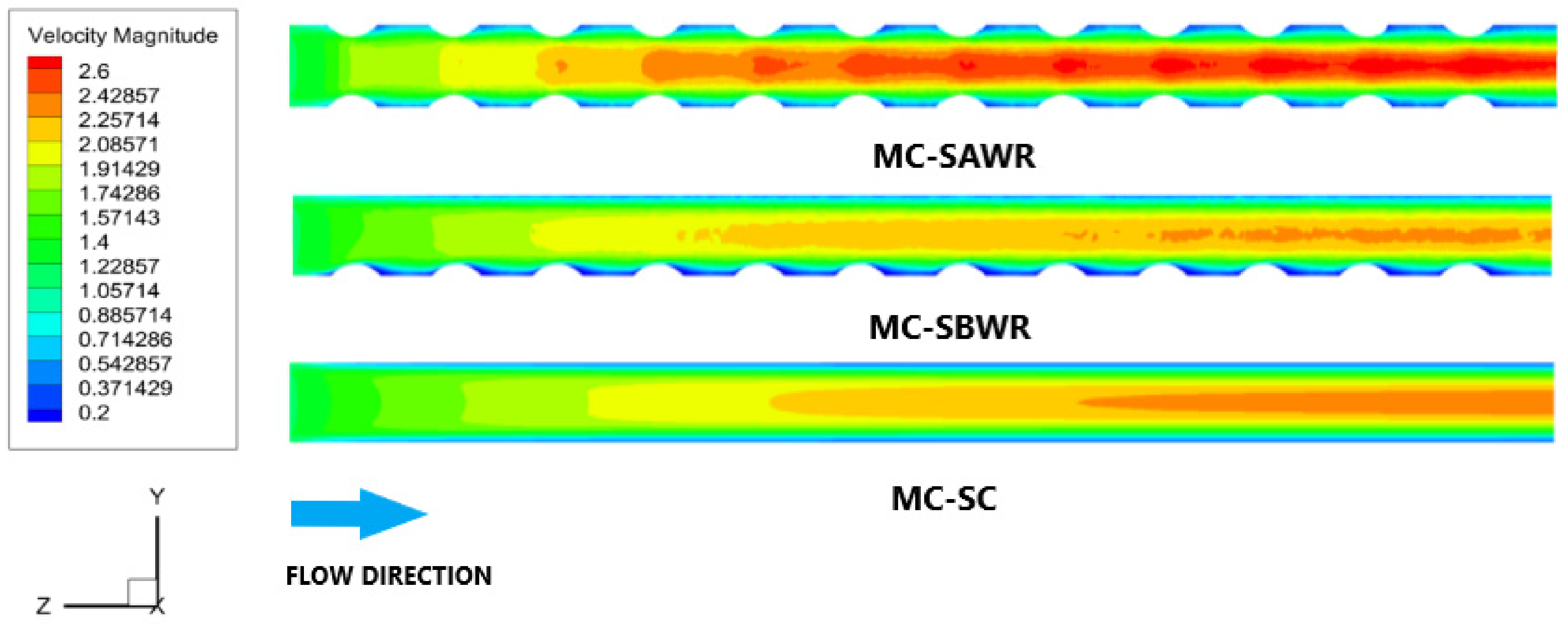
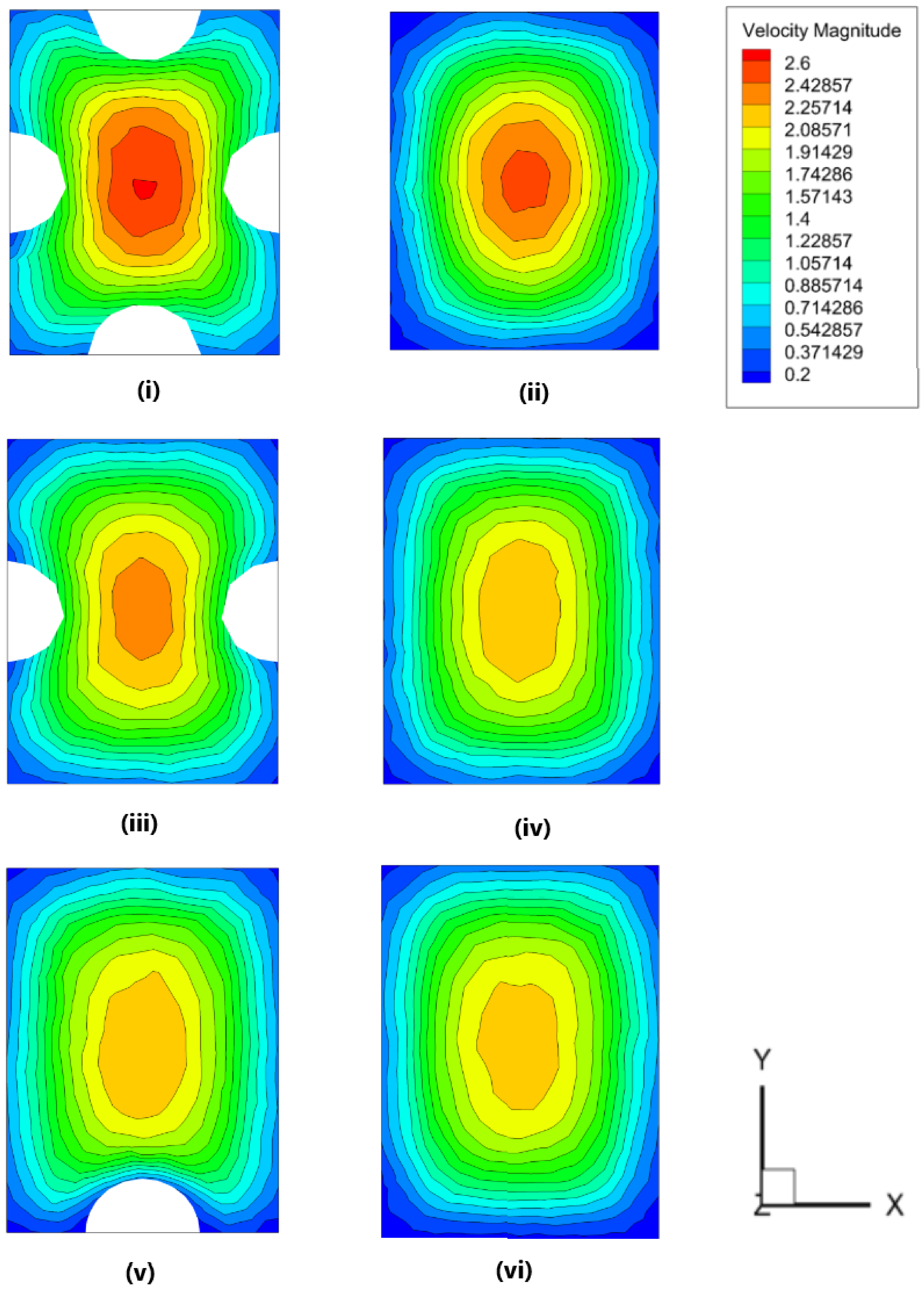
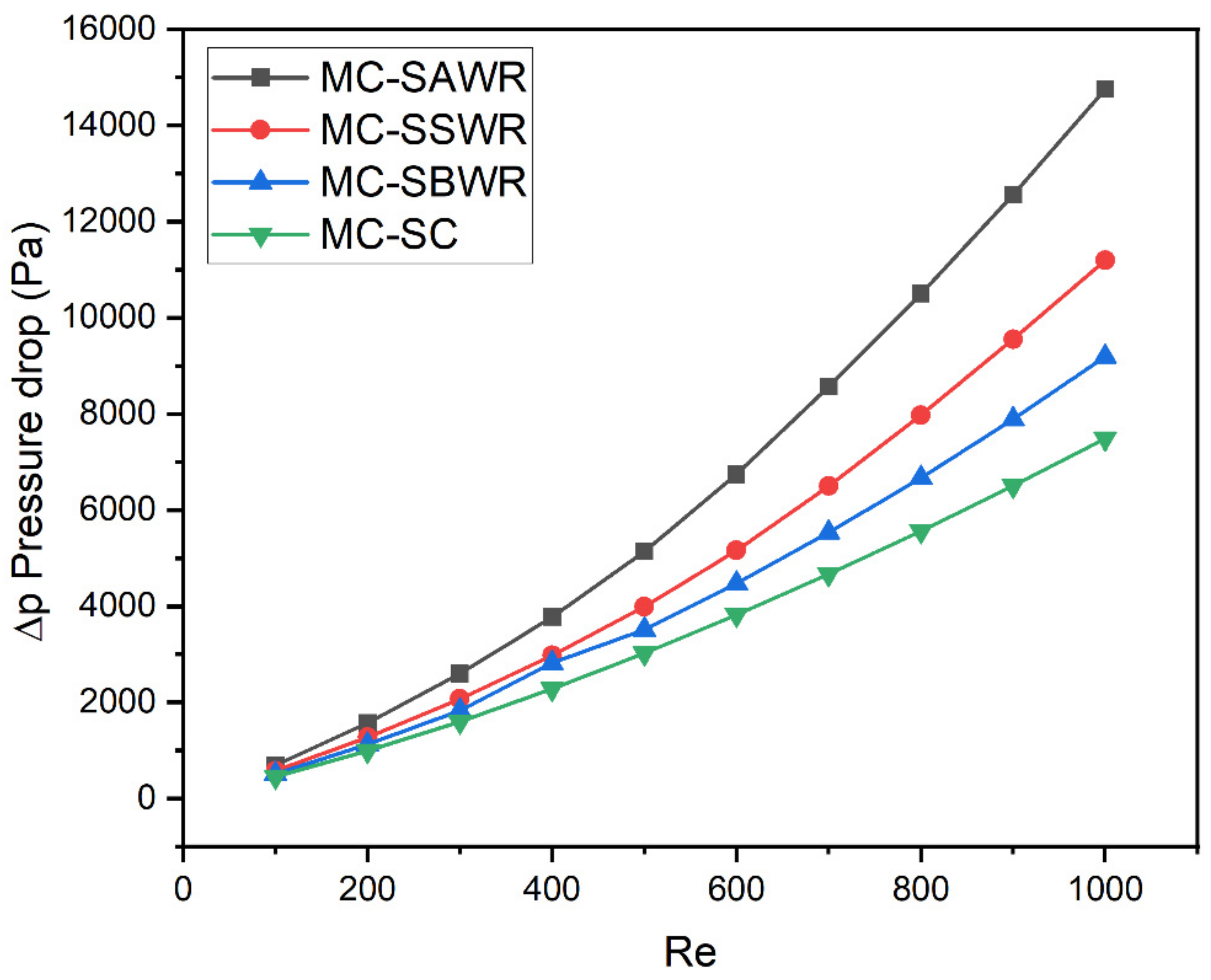
3.2. Flow Characteristics

Figure 10 displays velocity contours inside the microchannel for various configurations of MCHS at Re = 500. It is apparent that the addition of symmetrical ogive rib configurations inside smooth MCHS significantly affects the growth of the hydrodynamic boundary layer. MCHS with symmetrical ogive rib configurations have a shorter developing region than smooth MCHS because the addition of symmetrical ogive ribs to channel walls locally increases the flow velocity due to a decrease in the channel area. Figure 11 illustrates the velocity contours for MC-SAWR, MC-SBWR, and MC-SSWR configurations in the X-Y plane at two distinct regions, namely z = 5 mm and z = 5.34 mm. In MC-SAWR, MC-SSWR, and MC-SBWR, the flow continuously converges and diverges along the channel length, as visible in Figure 10. The presence of symmetrical ogive ribs on the channel walls forms convergence regions for flow by restricting the channel area. In symmetrical ogive ribs, the back ogive rib on the downside of the front ogive rib facilitates the divergence of the flow by gradually increasing the flow area. Additionally, the back ogive rib in symmetrical ogive ribs prevents flow separation and formation of recirculation zones downstream of the front ogive rib, thus reducing the additional pressure losses inside the channel. The MC-SSWR configuration has higher flow velocity inside the channel because the presence of symmetrical ogive ribs on all channel walls causes greater convergence of flow as compared to MC-SBWR and MC-SSWR configurations where symmetrical ogive ribs are present on only the side channel walls and the bottom channel wall, respectively. Although symmetrical ogive rib configurations inside MCHS improve the local flow velocity for forced convection, they cause a greater pressure drop inside the channel compared to the MC-SC (smooth MCHS) configuration.
Figure 12 illustrates the pressure drop for various configurations of MCHS at different Re values. The MC-SC configuration has the least pressure drop because frictional losses due to wall shear between flow and smooth channel walls only account for pressure drop. However, the inclusion of symmetrical ogive rib configurations inside the smooth channel continuously disturbs the flow due to the convergence and divergence of flow along the channel length. Flow convergence due to the presence of symmetrical ogive rib configurations inside the channel causes a greater drop in flow pressure. Therefore, MCHS configurations with symmetrical ogive ribs have more pressure drop than the MC-SC configuration. From Figure 12, it is visible that pressure drop tends to rise with Re because of an increase in wall shear at higher flow velocities. The MC-SAWR configuration has the highest pressure drop due to more flow convergence as a result of a greater reduction in the channel area for flow caused by the inclusion of symmetrical ogive ribs on all channel walls.

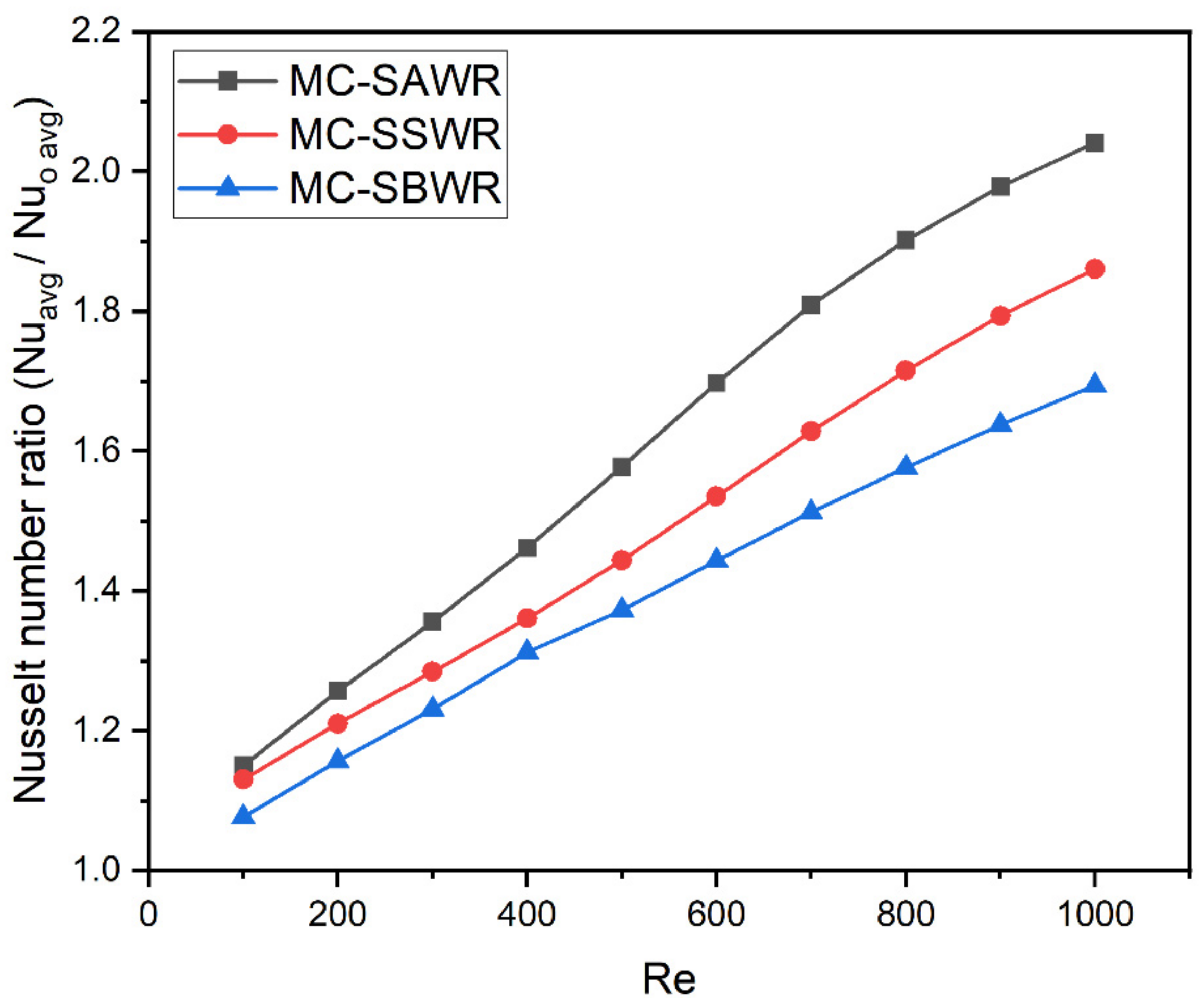
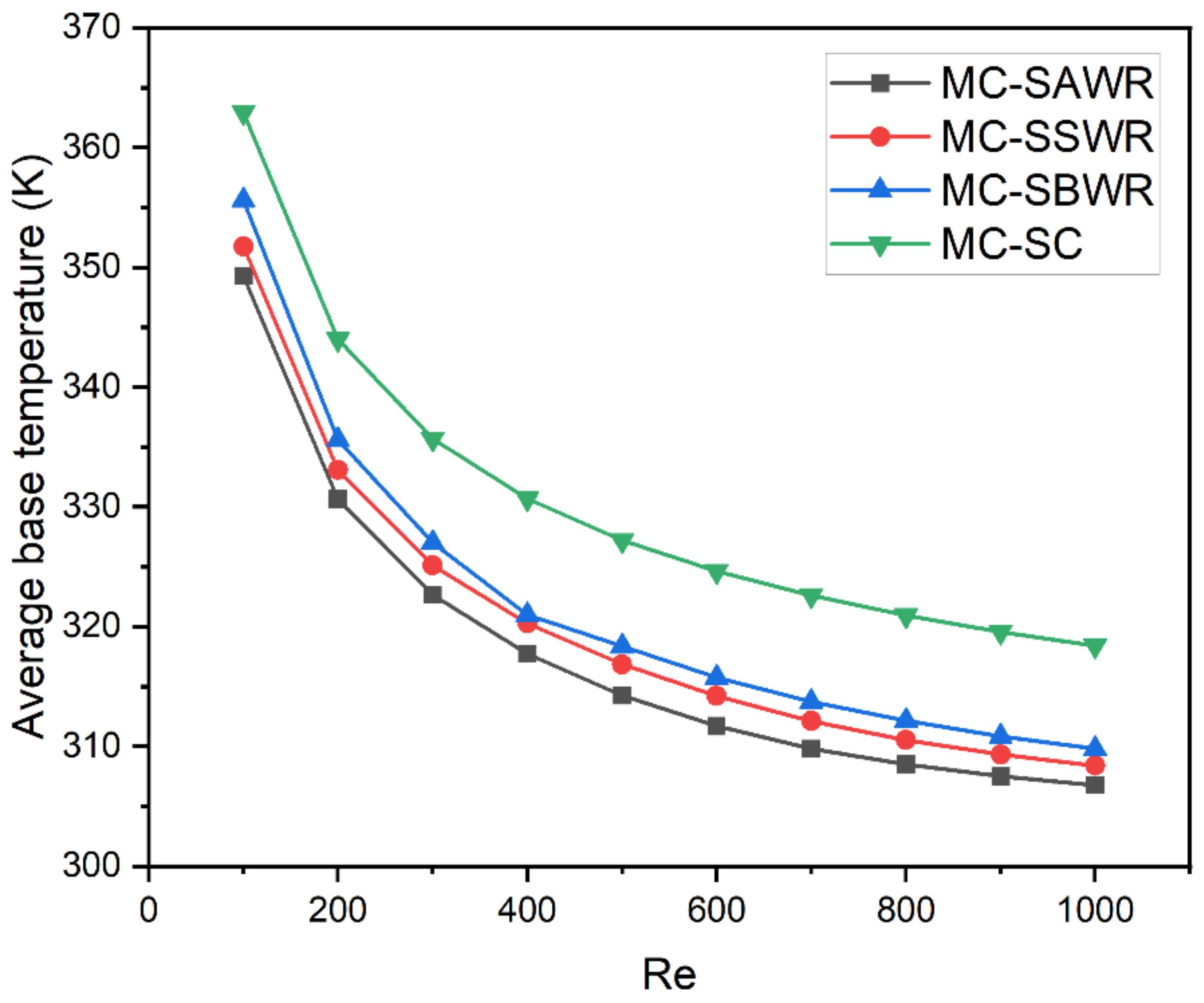
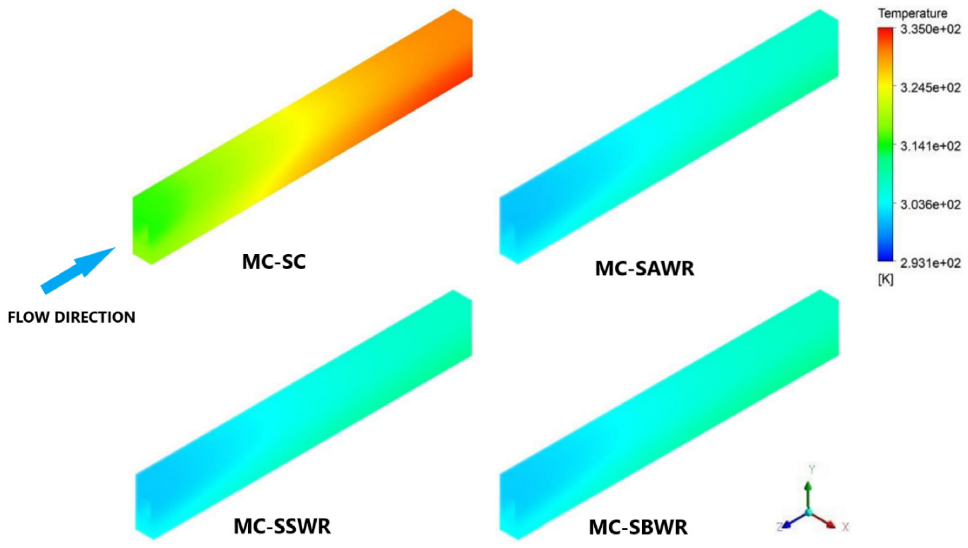
3.3. Thermal Characteristics

Nusselt number ratio ( N u a v g / N u 0   a v g ) is used to compare the convective heat transfer performance of MCHS with symmetrical ogive rib configurations and smooth MCHS. Figure 13 displays the variation of N u a v g / N u 0   a v g   ratio with Reynolds number for various configurations of MCHS with symmetrical ogive ribs. The convective heat transfer coefficient is greatly influenced by Reynolds number since an increase in velocity reduces the thermal boundary layer thickness, resulting in an increased heat transfer coefficient. For all Reynolds numbers, the N u a v g / N u 0   a v g ratio for all MCHS configurations with symmetrical ogive ribs is greater than one, indicating that the inclusion of symmetrical ogive ribs significantly improves the Nusselt number of smooth MCHS. This enhancement in the average Nusselt number is attributed to the increase in the local heat transfer coefficient caused by high local flow velocity along the channel length compared to smooth MCHS. The improvement in the average Nusselt number tends to increase with a rise in Reynolds number for MCHS with symmetrical ogive rib configurations. MC-SAWR configuration exhibits the highest N u a v g / N u 0   a v g at all Reynolds numbers due to the greater improvement in local heat transfer coefficient resulting from flow convergence along the channel length. MC-SAWR, MC-SSWR, and MC-SBWR configurations improve the Nusselt number of smooth MCHS by 1.14–2.04, 1.13–1.86, and 1.07–1.69 times, respectively, within the Reynolds number range of 100–1000.
Figure 14 illustrates the variation in thermal resistance ( R t h ) with Reynolds number (Re) for different MCHS configurations. Thermal resistance is a crucial measure of MCHS performance, as low thermal resistance enables the efficient dissipation of a large amount of heat. Thermal resistance decreases with increasing Reynolds number due to the improvement in Nusselt number at higher Re values. Smooth MCHS has the highest thermal resistance among the considered configurations due to its low Nusselt number and small available wall surface area, which increase the thermal resistance for convective heat transfer between the fluid and channel walls. The inclusion of symmetrical ogive ribs inside the channel significantly reduces the thermal resistance of MCHS by improving the Nusselt number and wall surface area available for heat transfer. The MC-SAWR configuration exhibits the lowest thermal resistance due to its high Nusselt number and greater surface area available for heat dissipation. At Re = 1000, the MC-SAWR configuration shows the maximum reduction in thermal resistance, with a 46% decrease compared to the MC-SC configuration. Meanwhile, the MC-SSWR and MC-SBWR configurations lower the thermal resistance of smooth MCHS by 39.6% and 34%, respectively, at Re = 1000.
Figure 15 depicts the variations in the average base wall temperature with Re for different configurations of MCHS. The base wall temperature ( T b ) decreases with the Reynolds number due to increased heat dissipation at higher mass flow rates, which is facilitated by a high Nusselt number. The MC-SC configuration exhibits the highest average base wall temperature at all Re values due to poor heat dissipation caused by high thermal resistance. However, the inclusion of symmetrical ogive rib configurations on the channel walls significantly reduces the average base wall temperature of MCHS by enhancing its ability to dissipate heat and lowering its thermal resistance for convection. At Re = 1000, the MC-SC configuration exhibits its lowest temperature, i.e., 319 K, while the highest average base wall temperature exhibited by any symmetrical ogive ribs configuration at Re = 1000 is 309 K. This confirms that MCHS with symmetrical ogive rib configurations provide superior cooling performance than smooth MCHS. The MC-SAWR configuration exhibits the lowest average base wall temperature at all Re values because of its low thermal resistance that enables it to dissipate a large amount of heat. Effective thermal management is crucial for ensuring the safe operation and reliability of electronic chips. Figure 16 illustrates the temperature distribution for the considered MCHS configurations. The smooth channel exhibits a more non-uniform temperature distribution, inducing thermal stresses in both the MCHS and the host electronic chip, thereby reducing their safety and reliability. In contrast, MCHS with symmetrical ogive ribs configurations exhibits lower and more uniform temperature distribution, demonstrating that these modified MCHS designs not only improve MCHS thermal performance but also enhance the safety and integrity of the host electronic chip.

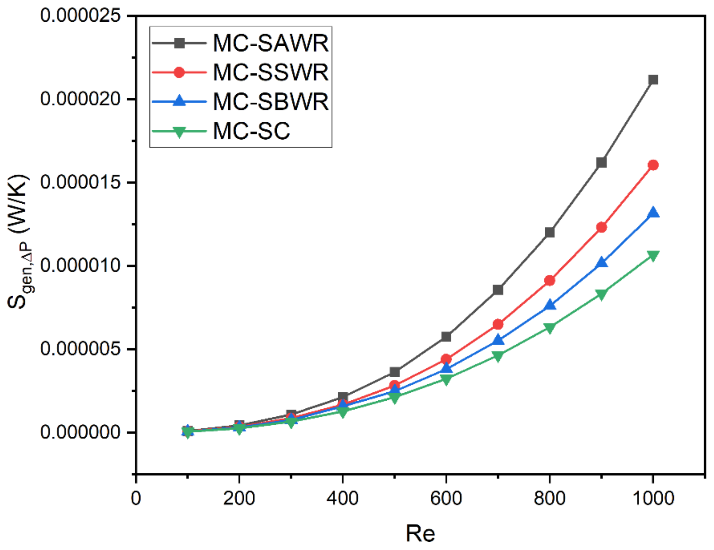
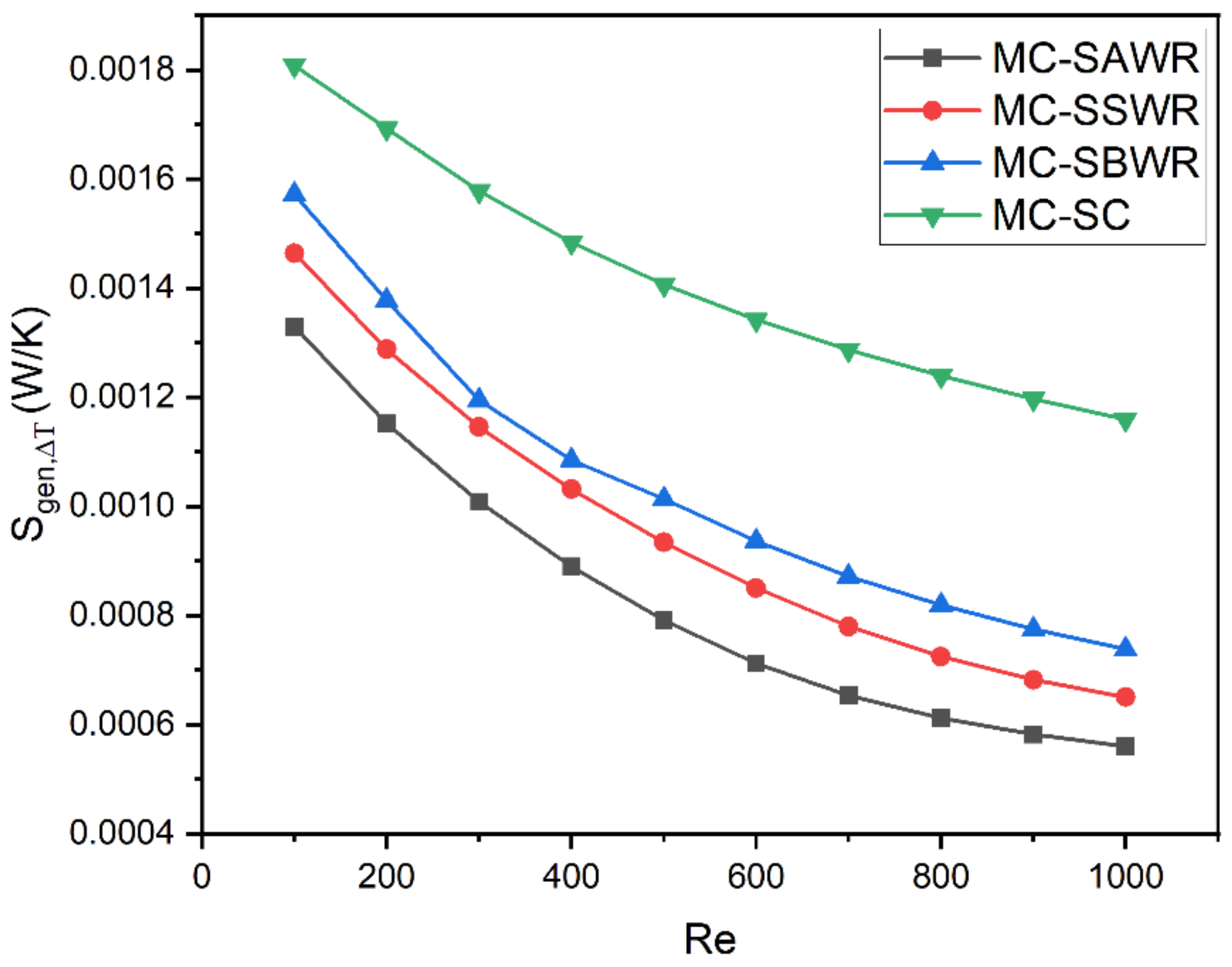
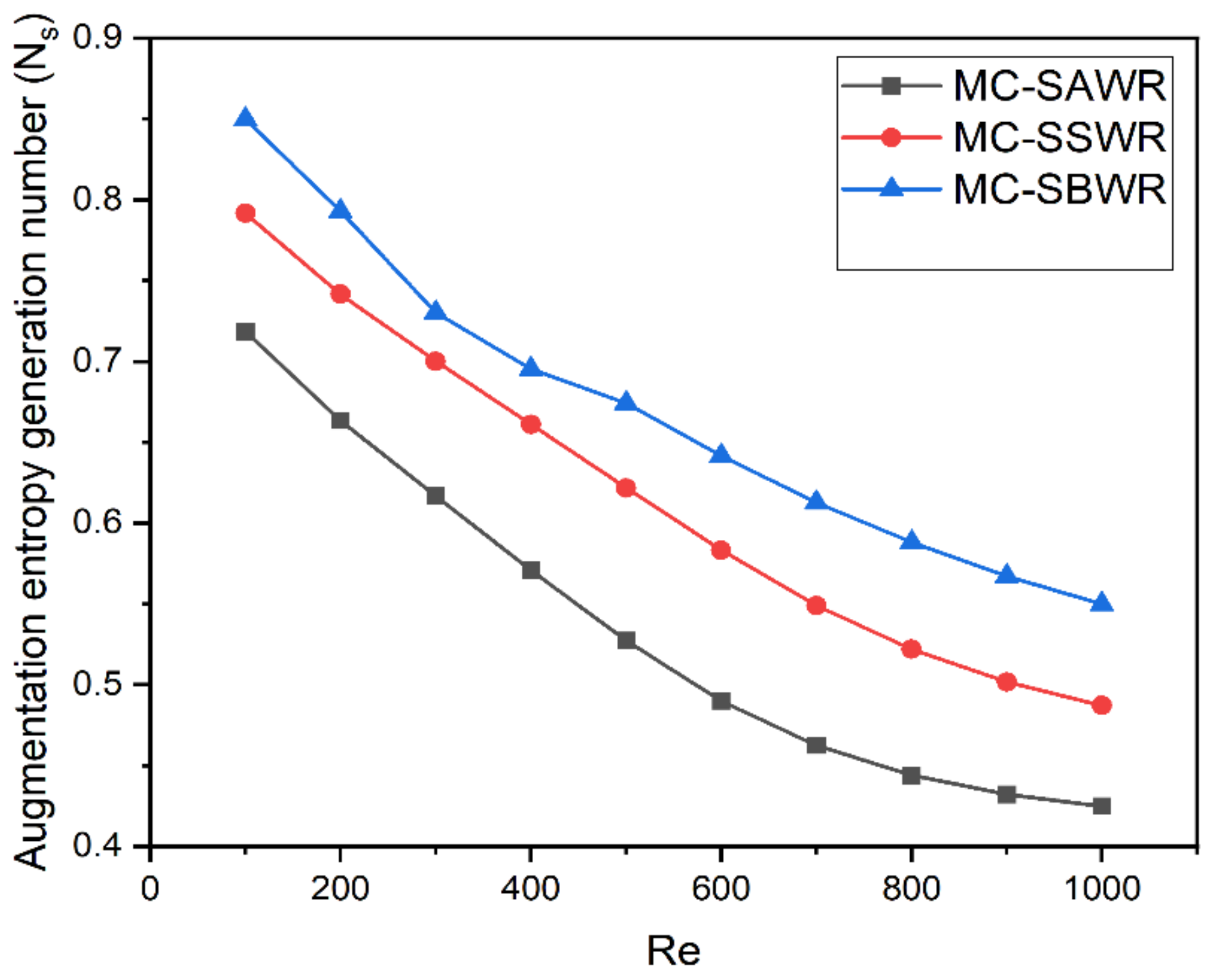
3.4. Entropy Generation Analysis

To evaluate the effectiveness of different MCHS designs from the standpoint of the second law of thermodynamics, it is important to calculate the irreversibilities related to fluid movement and heat transfer. As a general rule, smaller entropy values lead to better performance since they represent fewer irreversibilities and more available energy for fluid flow and heat transfer. In MCHS, the entropy generation rate due to pressure drop ( S ˙   g e n ,   Δ P ) is used to evaluate the irreversibilities related to flow due to pressure losses, while the entropy generation rate due to heat transfer ( S ˙   g e n ,   Δ T ) is used to evaluate the irreversibilities resulting from heat transfer. Figure 17 shows the trend between entropy generation rates due to pressure drop ( S ˙   g e n ,   Δ P ) and the Reynolds number for various MCHS configurations. Pressure losses in the channel increase with flow velocity, leading to an increase in S ˙   g e n ,   Δ P with Re. Among the considered MCHS configurations, MC-SC configuration has the smallest S ˙   g e n ,   Δ P due to the least pressure drop inside the channel. In contrast, MCHS with symmetrical ogive rib configurations have a high S ˙   g e n ,   Δ P values because of large pressure losses inside the channel resulting from the disturbance of flow by ogive ribs. At all Reynolds numbers, MC-SAWR exhibits the highest S ˙   g e n ,   Δ P due to greater pressure drop compared to other considered MCHS configurations.
Figure 18 shows how the entropy generation rate due to heat transfer ( S ˙   g e n ,   Δ T ) varies with Re for different MCHS configurations. The trend in the graph is decreasing with increasing Re because more heat is transferred at higher mass flow rates. Smooth MCHS has the highest entropy generation rate due to heat transfer because its large thermal resistance results in poor heat dissipation between the fluid and channel walls. MCHS configurations with symmetrical ogive ribs generate a lower S ˙   g e n ,   Δ T than MC-SC because of their ability to dissipate a larger amount of heat from the channel walls to the fluid due to lower thermal resistance for convection. MC-SAWR generates the lowest S ˙   g e n ,   Δ T because its low thermal resistance allows it to efficiently dissipate more heat.
Figure 19 illustrates the variation of the Bejan number (Be) with the Reynolds number (Re) for different MCHS configurations. The Bejan number is calculated to evaluate the contribution of the entropy generation rate due to heat transfer ( S ˙   g e n ,   Δ T ) to the total entropy generation rate ( S ˙   g e n ) associated with the MCHS. At all Reynolds number ranges, the Bejan number for all considered MCHS configurations is greater than 0.96. This implies that irreversibilities related to heat transfer account for more than 96% of the total entropy generation rate associated with the MCHS. The entropy generation rate associated with pressure drop is almost negligible at lower Reynolds numbers, while it slightly increases at higher Reynolds numbers due to an increase in pressure drop. The Bejan number tends to decrease with Re because of a reduction in S ˙   g e n ,   Δ T at higher Re. Moreover, the inclusion of symmetrical ogive ribs inside the channel significantly reduces the Bejan number by decreasing the irreversibilities due to heat transfer. The lowest Bejan number for the MC-SAWR configuration at all Re values indicates that this configuration shows the maximum reduction in irreversibilities associated with MCHS due to heat transfer.
Comparing the augmentation entropy generation number ( N s ) provides insight into the effectiveness of symmetrical ogive rib configurations in reducing irreversibilities inside MCHS. Figure 20 presents the augmentation entropy generation number ( N s ) for various MCHS configurations at Reynolds numbers between 100 and 1000. At all Re values, the augmentation entropy generation number ( N s ) is less than one for all symmetrical ogive rib configurations, indicating that incorporating these ribs on channel walls minimizes the total entropy generation rate ( S ˙   g e n ) associated with smooth MCHS. Augmentation entropy generation number ( N s ) less than unity also suggests that a reduction in S ˙   g e n ,   Δ T has a more significant impact on ( S ˙   g e n ) than the rise in S ˙   g e n ,   Δ P . As Re increases, N s shows a decreasing trend with Re because a reduction in the total entropy generation decreases due to a reduction in the total entropy generation rate. At Re = 1000, MC-SAWR, MC-SSWR, and MC-SBWR configurations decrease the total entropy generation rate associated with smooth MCHS by 58%, 52%, and 46%, respectively. Among all considered configurations, MC-SAWR has the lowest N s values, demonstrating its effectiveness in dissipating heat with fewer irreversibilities.

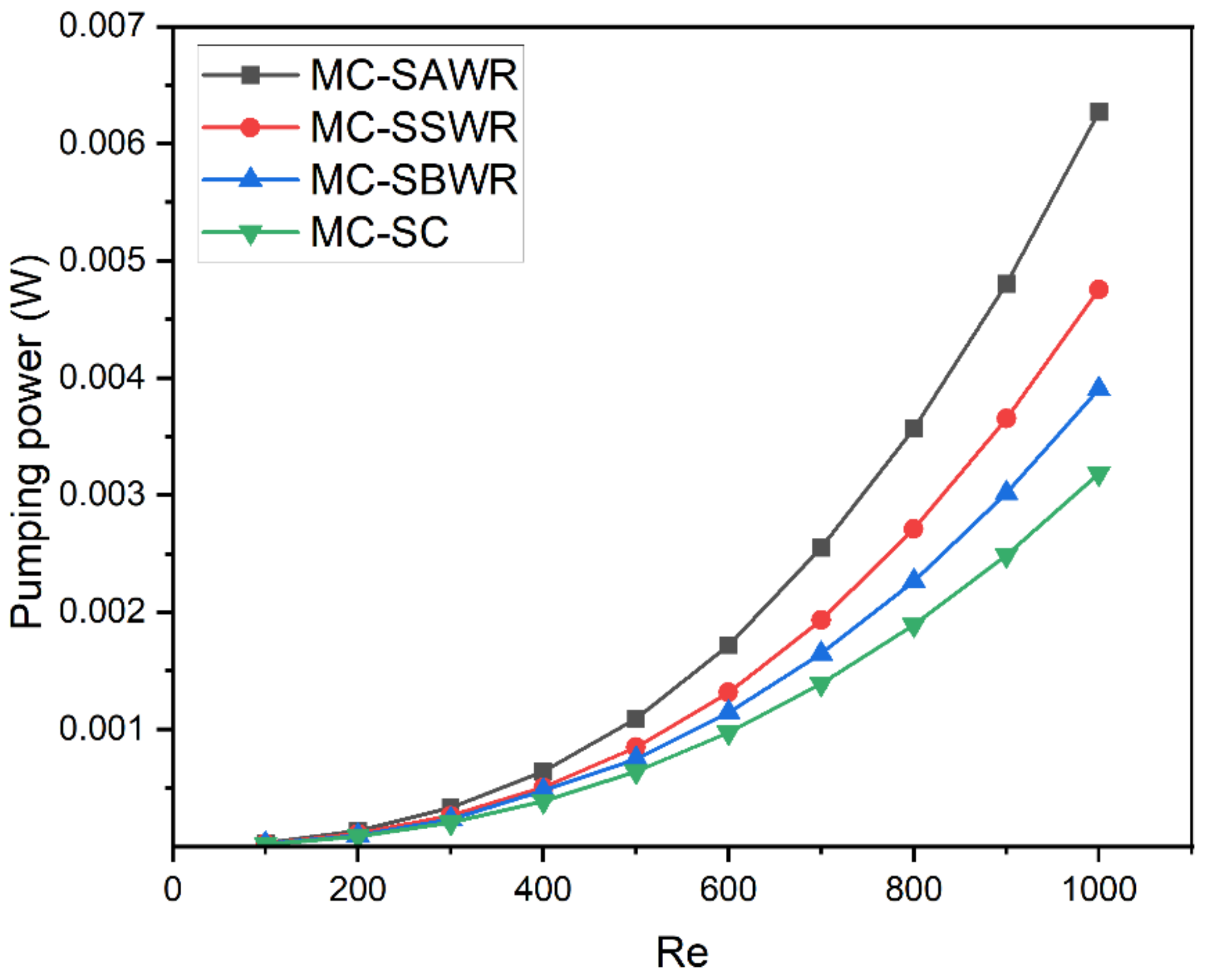
3.5. Pumping Power Requirement

Figure 21 illustrates the pumping power needed for different MCHS configurations at various Reynolds numbers (Re). It is clear that incorporating symmetrical ogive ribs on the channel walls of MCHS enhances its thermal performance but also increases the required pumping power due to an increase in pressure drop within the channel. This pumping power demand tends to rise with an increase in Reynolds number because of the greater pressure drop at higher Re. Among all considered configurations, MC-SAWR demands the highest pumping power because of the greater pressure drop inside the channel.

3.6. Thermal Enhancement Factor ( η )

Symmetrical ogive rib configurations improve the thermal performance of MCHS at the expense of pumping power. Therefore, the thermal enhancement factor ( η ) is used as a criterion to evaluate the impact of symmetrical ogive ribs on the overall hydrothermal performance of MCHS. This factor compares the improvement in the Nusselt number with the increase in pressure losses due to symmetrical ogive ribs. Figure 22 shows the thermal enhancement factor for various MCHS configurations at different Re values. The thermal enhancement factor increases with Re because a greater improvement in the Nusselt number occurs at higher flow velocities. At Re values between 100 and 400, MC-SSWR shows the maximum thermal enhancement factor, while MC-SAWR configuration shows the lowest, as it improves the thermal performance of MCHS at the expense of a relatively larger pressure drop compared to other MCHS configurations. However, at Re values greater than 400, MC-SAWR configuration shows the maximum thermal enhancement factor due to a relatively larger improvement in the Nusselt number. All MCHS configurations with symmetrical ogive ribs have a thermal enhancement factor greater than one, except MC-SAWR at Re = 100. Therefore, at Re = 100, MC-SAWR configuration is not effective from the standpoint of the overall hydrothermal performance as pressure losses due to symmetrical ogive ribs are significantly greater than the corresponding Nusselt number improvement.

3.7. Exergy Analysis

In convective heat transfer, the term “thermal transport efficiency” refers to the effective utilization of thermal energy [24]. Figure 23 shows the relationship between thermal transport efficiency ( η t ) of various MCHS configurations and the Reynolds number. Thermal transport efficiency tends to increase with Re because the fluid dissipates more heat energy due to a higher Nusselt number. Due to the large thermal resistance between the walls of the MC-SC configuration and the fluid, poor heat dissipation occurs through convection, resulting in MC-SC having the lowest thermal transport efficiency values at all Re values. Conversely, MCHS with symmetrical ogive rib configurations demonstrates higher thermal transport efficiency than MC-SC due to greater heat transfer between channel walls and fluid resulting from low thermal resistance for convection. At all Re values, the MC-SAWR, MC-SSWR, and MC-SBWR configurations increase the thermal transport efficiency of smooth MCHS by more than 3%. Among all configurations considered, MC-SAWR exhibits the highest thermal transport efficiency because of its low thermal resistance which allows it to efficiently dissipate a large amount of heat from the channel.

4. Conclusions

The present study proposes a novel modification to the smooth microchannel heat sink (MCHS) with symmetrical ogive ribs that provides greater thermal performance enhancement with minimal pressure losses. Numerical analyses have been performed to study the hydraulic and thermal characteristics of MCHS with different configurations of symmetrical ogive ribs, and the best configuration has been found by evaluating the augmentation entropy generation number and thermal enhancement factor. The results show that:
  • The inclusion of symmetrical ogive shape rib configurations on smooth MCHS channel walls improves its thermal performance by increasing the average Nusselt number. The MC-SAWR configuration gives the maximum Nusselt number improvement, increasing the Nusselt number of smooth MCHS by 2.04 times at Re = 1000.
  • Symmetrical ogive rib configurations lower the thermal resistance of MCHS by improving the heat transfer coefficient and increasing the channel wall surface area for heat dissipation. The MC-SAWR configuration shows the maximum reduction in thermal resistance, reducing the thermal resistance of smooth MCHS by 46%.
  • The addition of symmetrical ogive ribs on smooth MCHS channel walls is effective in reducing the entropy generation rate associated with MCHS. MCHS configurations with symmetrical ogive ribs demonstrate augmentation entropy generation lower than one at all Re values, with the MC-SAWR configuration showing the lowest augmentation entropy generation value of 0.42, reducing the irreversibilities associated with smooth MCHS by 58%.
  • Symmetrical ogive ribs improve the thermal performance of MCHS, and they also result in a significant rise in pressure drop. Therefore, more external pumping energy is required for heat dissipation from MCHS.
  • The thermal enhancement factor is greater than one for MC-SSWR and MC-SBWR configurations at all Re values, while for MC-SAWR configuration, it is greater than one at all Re values except at Re = 100. A thermal enhancement factor greater than one implies that the improvement of MCHS performance due to symmetrical ogive ribs from a thermal standpoint is more significant than the deterioration of system performance due to high pumping power requirement.
  • Based on the augmentation entropy generation number and thermal enhancement factor criterion, the MC-SAWR configuration is the best configuration at Re greater than 100. Although the MC-SAWR configuration has a lower thermal enhancement factor than the MC-SSWR and MC-SBWR configurations at Re less than 400, this low thermal enhancement factor due to higher pressure losses is balanced by its lower augmentation entropy generation number, giving a superior cooling performance.

Author Contributions

Conceptualization, K.A., H.A. and I.U.D.; methodology, K.A., H.A., I.U.D. and F.A. (Faraz Ahmad); validation, K.A., H.A., F.A. (Faraz Ahmad), F.A. (Fayyaz Alam), N.S. and M.Z.Z.; investigation, K.A., H.A., I.U.D., N.S., M.Z.Z., A.A., F.A. (Faraz Ahmad), F.A. (Fayyaz Alam) and M.A.; writing—original draft preparation, K.A., I.U.D., F.A. (Fayyaz Alam) and H.A. All authors have read and agreed to the published version of the manuscript.

Funding

This research received no external funding.

Data Availability Statement

The data presented in this study are available upon request.

Acknowledgments

The authors acknowledge the support of UET Peshawar, for providing the computational facilities to conduct this research study.

Conflicts of Interest

The authors declare no conflict of interest.

Nomenclature

A Area ,   m 2
c p Specific   heat ,   J   Kg 1 K 1
D o r 
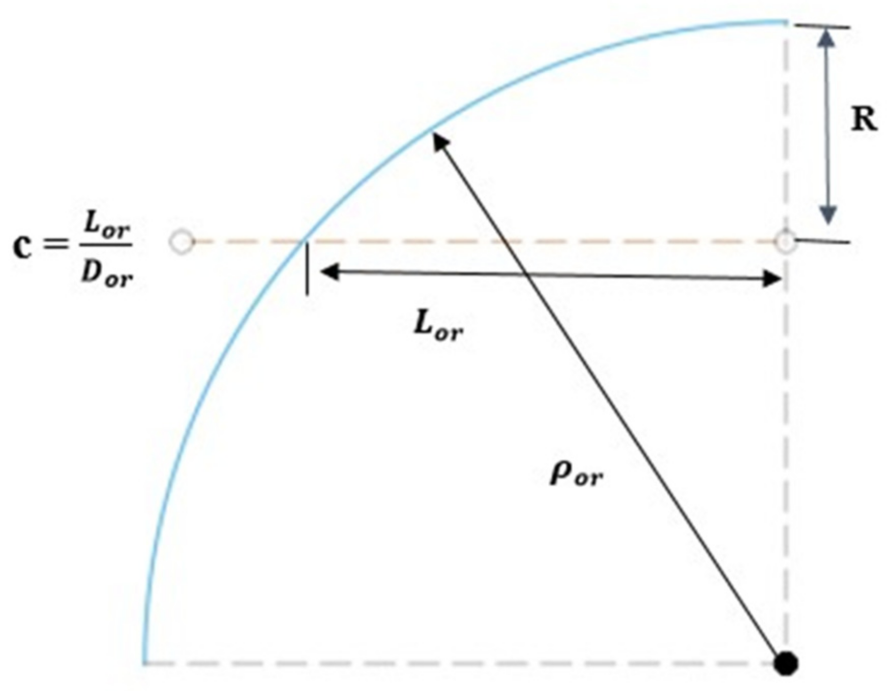
Diameter of ogive rib, mm
D h Hydraulic diameter, mm
fFriction factor
h a v g Heat   transfer   coefficient ,   W   m 2 K 1
HHeight, mm
H c h Height of channel, mm
k Thermal   conductivity ,   W   m 1 K 1
LLength, mm
L o r Length of ogive rib, mm
MCHSMicrochannel heat sink
MC-SCMicrochannel with smooth channel
MC-SAWRMCHS with ribs mounted on all channel walls
MC-SSWRMCHS with ribs mounted on side-channel walls
MC-SBWRMCHS with ribs mounted on only the bottom wall of the channel
N s Augmentation entropy generation number
NuNusselt number
Δ p Pressure drop, Pa
Q Heat   flux ,   W   m 2
ReReynolds number
R t h Thermal resistance, K/W
S Space   between   ogive   ribs ,   mm
S ˙ g e n   Total volumetric entropy generation rate
S ˙ g e n   Δ T Entropy generation rate due to heat transfer
S ˙ g e n   Δ P Entropy generation rate due to pressure drop
TTemperature, K
  T b Average base wall temperature
Δ TTemperature difference, K
u m Mean velocity, m/s
uVelocity component in x direction, m/s
vVelocity component in y direction, m/s
wVelocity component in z direction, m/s
WWidth, mm
W c h Width of channel, mm
Greek Symbols
ρ Density ,   kg   m 3
μ Dynamic viscosity, Pa s
η Thermal enhancement factor
η t Thermal transport efficiency
Subscripts
wWall
sSolid
fFluid
thTotal
inInlet
outOutlet

References

  1. Tuckerman, D.B.; Pease, R.F.W. High-performance heat sinking for VLSI. IEEE Electron. Device Lett. 1981, 2, 126–129. [Google Scholar] [CrossRef]
  2. Wang, H.; Chen, Z.; Gao, J. Influence of geometric parameters on flow and heat transfer performance of micro-channel heat sinks. Appl. Therm. Eng. 2016, 107, 870–879. [Google Scholar] [CrossRef]
  3. Dewan, A.; Srivastava, P. A review of heat transfer enhancement through flow disruption in a microchannel. J. Therm. Sci. 2015, 24, 203–214. [Google Scholar] [CrossRef]
  4. Datta, A.; Sharma, V.; Sanyal, D.; Das, P. A conjugate heat transfer analysis of performance for rectangular microchannel with trapezoidal cavities and ribs. Int. J. Therm. Sci. 2019, 138, 425–446. [Google Scholar] [CrossRef]
  5. Wang, G.; Niu, D.; Xie, F.; Wang, Y.; Zhao, X.; Ding, G. Experimental and numerical investigation of a microchannel heat sink (MCHS) with micro-scale ribs and grooves for chip cooling. Appl. Therm. Eng. 2015, 85, 61–70. [Google Scholar] [CrossRef]
  6. Ahmad, F.; Cheema, T.A.; Rehman, M.M.U.; Ilyas, M.; Park, C.W. Thermodynamic Analysis of Microchannel Heat Sink with Cylindrical Ribs and Cavities. J. Heat Transf. 2020, 142, 092503. [Google Scholar] [CrossRef]
  7. Khan, A.A.; Kim, S.-M.; Kim, K.-Y. Performance Analysis of a Microchannel Heat Sink with Various Rib Configurations. J. Thermophys. Heat Transf. 2016, 30, 782–790. [Google Scholar] [CrossRef]
  8. Ghani, I.A.; Kamaruzaman, N.; Sidik, N.A.C. Heat transfer augmentation in a microchannel heat sink with sinusoidal cavities and rectangular ribs. Int. J. Heat Mass Transf. 2017, 108, 1969–1981. [Google Scholar] [CrossRef]
  9. Li, Y.; Xia, G.; Ma, D.; Jia, Y.; Wang, J. Characteristics of laminar flow and heat transfer in microchannel heat sink with triangular cavities and rectangular ribs. Int. J. Heat Mass Transf. 2016, 98, 17–28. [Google Scholar] [CrossRef]
  10. Zhai, Y.; Xia, G.; Liu, X.; Li, Y. Exergy analysis and performance evaluation of flow and heat transfer in different micro heat sinks with complex structure. Int. J. Heat Mass Transf. 2015, 84, 293–303. [Google Scholar] [CrossRef]
  11. Zhai, Y.; Xia, G.; Liu, X.; Li, Y. Heat transfer in the microchannels with fan-shaped reentrant cavities and different ribs based on field synergy principle and entropy generation analysis. Int. J. Heat Mass Transf. 2014, 68, 224–233. [Google Scholar] [CrossRef]
  12. Li, P.; Luo, Y.; Zhang, D.; Xie, Y. Flow and heat transfer characteristics and optimization study on the water-cooled microchannel heat sinks with dimple and pin-fin. Int. J. Heat Mass Transf. 2018, 119, 152–162. [Google Scholar] [CrossRef]
  13. Rehman, M.M.U.; Cheema, T.A.; Ahmad, F.; Abbas, A.; Malik, M.S. Numerical investigation of heat transfer enhancement and fluid flow characteristics in a microchannel heat sink with different wall/design configurations of protrusions/dimples. Heat Mass Transf. 2020, 56, 239–255. [Google Scholar] [CrossRef]
  14. Rehman, M.M.U.; Cheema, T.A.; Ahmad, F.; Khan, M.; Abbas, A. Thermodynamic Assessment of Microchannel Heat Sinks with Novel Sidewall Ribs. J. Thermophys. Heat Transf. 2020, 34, 243–254. [Google Scholar] [CrossRef]
  15. Ahmad, F.; Cheema, T.A.; Ur Rehman, M.M.; Abbas, A.; Park, C.W. Thermal enhancement of microchannel heat sink using rib surface refinements. Numer. Heat Transf. Part A Appl. 2019, 76, 851–870. [Google Scholar] [CrossRef]
  16. Li, Y.; Xia, G.; Jia, Y.; Ma, D.; Cai, B.; Wang, J. Effect of geometric configuration on the laminar flow and heat transfer in microchannel heat sinks with cavities and fins. Numer. Heat Transf. Part A Appl. 2017, 71, 528–546. [Google Scholar] [CrossRef]
  17. Xia, G.; Chai, L.; Wang, H.; Zhou, M.; Cui, Z. Optimum thermal design of microchannel heat sink with triangular reentrant cavities. Appl. Therm. Eng. 2011, 31, 1208–1219. [Google Scholar] [CrossRef]
  18. Ahmad, F.; Cheema, T.A.; Khan, A.; Mohib-Ur-Rehman, M.; Yildizhan, H. Hydrothermal Investigation of the Performance of Microchannel Heat Sink with Ribs Employed on Side Walls. J. Non-Equilib. Thermodyn. 2021, 46, 255–272. [Google Scholar] [CrossRef]
  19. Zhang, S.; Ahmad, F.; Ali, H.; Ali, S.; Akhtar, K.; Ali, N.; Badran, M. Computational Study of Hydrothermal Performance of Microchannel Heat Sink with Trefoil Shape Ribs. IEEE Access 2022, 10, 74412–74424. [Google Scholar] [CrossRef]
  20. Ali, S.; Ahmad, F.; Akhtar, K.; Habib, N.; Aamir, M.; Giasin, K.; Vafadar, A.; Pimenov, D.Y. Numerical Investigation of Microchannel Heat Sink with Trefoil Shape Ribs. Energies 2021, 14, 6764. [Google Scholar] [CrossRef]
  21. Ali, S.; Ahmad, F.; Hassan, M.; Rehman, Z.; Wadood, A.; Ahmad, K.; Park, H. Thermo-Fluid Characteristics of Microchannel Heat Sink with Multi-Configuration NACA 2412 Hydrofoil Ribs. IEEE Access 2021, 9, 128407–128416. [Google Scholar] [CrossRef]
  22. ‘Ogive Shape’, Wikipedia. Available online: https://en.wikipedia.org/wiki/Ogive#:~:text=An%20ogive%20or%20ogival%20arch,the%20same%20as%20the%20width (accessed on 8 August 2021).
  23. Chalia, S.; Bharti, M.K. Mathematical modeling of ogive forebodies and nose cones. Int. Res. J. Eng. Technol. IRJET 2016, 3, 744–747. [Google Scholar]
  24. Zimparov, V. Extended performance evaluation criteria for enhanced heat transfer surfaces: Heat transfer through ducts with constant wall temperature. Int. J. Heat Mass Transf. 2000, 43, 3137–3155. [Google Scholar] [CrossRef]
Figure 1. Description of MCHS computational domain.
Energies 16 02783 g001
Figure 2. Ogive shape geometry profile.
Energies 16 02783 g002
Figure 3. Grid for the solid domain of MCHS.
Energies 16 02783 g003
Figure 4. Grid for the fluid domain of MCHS.
Energies 16 02783 g004
Figure 5. Velocity profile for different grid sizes along height of channel in Z-Y plane at x = 0.30 mm and z = −4.9 mm.
Energies 16 02783 g005
Figure 6. Nusselt number vs. Re for smooth channel MCHS experimental [5] and numerical.
Energies 16 02783 g006
Figure 7. Friction factor (f) vs. Re for smooth channel MCHS experimental [5] and numerical.
Energies 16 02783 g007
Figure 8. Nusselt number (Nu) vs. Re for ribbed MCHS experimental [5] and numerical.
Energies 16 02783 g008
Figure 9. Friction factor (f) vs. Re for ribbed MCHS experimental [5] and numerical.
Energies 16 02783 g009
Figure 10. Velocity contours for various MCHS configurations at Re = 500 in X-Z plane at x = 0.30 mm.
Energies 16 02783 g010
Figure 11. Velocity contours for different MCHS configurations in the X-Z plane at two different distances along the z-axis: (i) MC-SAWR (z = 5 mm), (ii) MC-SAWR (z = 5.34 mm), (iii) MC-SSWR (z = 5 mm), (iv) MC-SSWR (z = 5.34 mm), (v) MC-SBWR (z = 5 mm), (vi) MC-SBWR (z = 5.34 mm).
Energies 16 02783 g011
Figure 12. Variation of pressure drop ( Δ p ) with Re for different MCHS configurations.
Energies 16 02783 g012
Figure 13. Variation of Nusselt number ratio ( N u a v g / N u 0   a v g ) with Re for different MCHS configurations.
Energies 16 02783 g013
Figure 14. Variation of thermal resistance ( R t h ) with Re for different MCHS configurations.
Energies 16 02783 g014
Figure 15. Variation of average base wall temperature ( T b ) with Re for various MCHS configurations.
Energies 16 02783 g015
Figure 16. Temperature distribution for various MCHS configurations at Re = 500.
Energies 16 02783 g016
Figure 17. Variation of entropy generation rate due to pressure drop ( S ˙   g e n ,   Δ P ) with Re for various MCHS configurations.
Energies 16 02783 g017
Figure 18. Variation of entropy generation rate due to heat transfer ( S ˙   g e n ,   Δ T ) with Re for various MCHS configurations.
Energies 16 02783 g018
Figure 19. Variation of Bejan number (Be) with Re for various MCHS configurations.
Energies 16 02783 g019
Figure 20. Variation of augmentation entropy generation number ( N s ) with Re for various MCHS configurations.
Energies 16 02783 g020
Figure 21. Variation of pumping power with Re for various MCHS configurations.
Energies 16 02783 g021
Figure 22. Variation of thermal enhancement factor ( η ) with Re for various MCHS configurations.
Energies 16 02783 g022
Figure 23. Variation of thermal transport efficiency ( η t ) with Re for various MCHS configurations.
Energies 16 02783 g023
Table 1. Thermo-physical properties of copper and water (Constant thermo-physical properties of water mentioned in Table 1 are given at 293.15 K).
PropertiesMaterials
CopperWater
Density kg / m 3 8978998.2
Specific heat J kg   K 3814182
Thermal conductivity W m   K 387.60.6
Dynamic viscosity kg m   s 0.001003
Table 2. Boundary conditions.
Inlet velocity
Inlet temperature
w = w i n
T i n = 293.15   K
Outlet pressure p = p o u t = 1   atm
Heat flux at y = 0 k s T s y = q w =   1 , 000 , 000   W / m 2
At solid–liquid interface u = v = w = 0
k s T s n = k f T f n
Adiabatic boundary T f z =   T s z = 0
Table 3. Grid number for different element sizes.
S. NoGrid ResolutionElement Size (mm)Grid Number
1Coarse mesh0.058379,267
2Medium0.048661,025
3Fine0.045810,563
4Very fine0.0411,058,252
Disclaimer/Publisher’s Note: The statements, opinions and data contained in all publications are solely those of the individual author(s) and contributor(s) and not of MDPI and/or the editor(s). MDPI and/or the editor(s) disclaim responsibility for any injury to people or property resulting from any ideas, methods, instructions or products referred to in the content.

