Abstract
With the development of urban underground space and increased infrastructure functions, both the scale of engineering construction and engineering difficulties have increased globally. In the construction of structures in soft strata, especially in coastal areas, the limited bearing capacity of the foundations poses a significant challenge. The composite pile technologies employing an organic combination of the rigid pile andthe flexible column can enable efficient soft ground treatment. In light of prominent global environmental issues, low-carbon energy-saving curing technologies have been rapidly developed for application in geotechnical engineering. This paper discusses progress in research on the mechanical properties of the efficient and low-carbon pile technologies, including the stiffened deep mixing (SDM) column, squeezed branch pile, pre-bored grouting plated nodular (PGPN) pile, precast cement pile reinforced by cemented soil with a variable section (PCCV), and carbonized composite pile (CCP). In addition, it reviews the technical characteristics and recent progress of feasible low-carbon energy-efficient curing technologies. The paper also proposes future directions for theoretical research and technological development of low-carbon pile technologies. The key contribution of this review is to provide insights into efficient and low-carbon pile technologies. In addition, the findings from the study of the pile technologies used in extra-thick soft strata also provide industry practitioners with a comprehensive guide regarding the specific applications and mechanical performance of the pile technologies, which can serve as a stepping stone to facilitate the technological development of the underground space industry.
1. Introduction
With the rapid development of the global economy and urbanization, the construction of infrastructure such as high-speed railways and expressways, and underground space exploitation, have undergone rapid change [,,,]. Both the construction scale and degree of engineering difficulty are at an unprecedentedly high level internationally. Moreover, deep soft and weak soils are employed widely in coastal and river areas; their low strength, large deformation, poor stability, and seismic performance pose significant challenges to various engineering construction projects [,] and are also the main cause of various engineering accidents [,,]. The existing technical specifications for the ground treatment primarily apply to soft soil foundations with a depth less than 20 m. Rigid pile composite foundations and pile foundations are mainly used for deeper soft soil strata, which are also the primary form of the foundation used for high-rise buildings, highways, and railway roadbeds, as well as bridge foundations. The main types of rigid piles and pile foundations are precast concrete (PC) piles, pipe piles, and bored piles [], which play an important role in infrastructure modernization and construction. However, conventional rigid piles are often expensive, and the seismic performance of PC piles does not adequately meet design requirements [,], thus limiting their application.
To overcome these problems, some novel types of composite piles have been developed in recent years, such as stiffened deep mixing (SDM) columns [] and pre-bored grouting planted nodular (PGPN) piles []. These piles consist of an organic combination of a flexible column and rigid pile, i.e., inserting the PC pile with different cross-sections into the deep mixing (DM) column. This combination can exploit the advantages of high bearing capacity of concrete piles, compensate for the low strength of the DM column, and improve the strength of the surrounding soil [,], significantly improving the performance of precast piles and expanding their application range. Thus, it has good potential for widespread application [,].
However, in recent years, there have been breakthroughs in both the pile types and materials used in mixing column technology. Two-way variable-section mixing pile technology, and powder and wet spraying integrated construction technology, have been popularized []. T-shaped deep mixing (TDM) columns [,] and squeezed branch piles as the variable-section piles are the choices for layered soft ground [,]. Furthermore, since the production process of conventional Portland cement consumes large amounts of resources and energy, and emits a large amount of harmful gases including CO2, dust, soot, and SO2, technologies employing Portland cement as a curing material can no longer satisfy the requirements of modern low-carbon environmental protection and sustainable development []. For this reason, new low-carbon energy-saving curing agents, such as blast furnace slag, steel slag, fly ash [,], and reactive magnesia [], which enable green and environmental protection, have been rapidly developed. In this paper, we review a series of novel pile technologies, with a focus on presenting the interface characteristics and vertical and horizontal bearing behaviors of the SDM column under the building loads, the bearing mechanism and failure mode of the SDM column-supported embankment, and the status of research into the squeezed branch pile and PGPN pile. Based on the studies of feasible low-carbon energy-efficient curing agents, a basis for the further development of variable-section composite pile technology and a carbonized composite pile (CCP) is proposed.
2. Current Status of Research on the SDM Column
The use of the SDM column as a composite pile originated at Hebei Cangzhou Machinery Construction Co., Ltd., Cangzhou, China, in 1994. The column is formed by inserting the PC or pre-stressed high-intensity concrete (PHC) piles, termed the inner core or cored pile, into the DM column, termed the outer core, after the construction of the DM column []. It is worth noting that the PC pile improved with cement-treated soil (PCCS) [,] is another term for the SDM column; however, despite some similarities in the configuration, they are nevertheless based on different ideas. The goal of the PCCS is to improve the bearing capacity of the PC pile with cemented soils. The design concept of the SDM column is to reinforce the DM column with reinforcement (i.e., concrete or an H-type steel pile). For the sake of consistency, the term “SDM column” has been adopted in this study. In 1998, Tianjin University and Hebei University of Technology conducted a series of model experiments and field tests on SDM columns and initially derived the bearing characteristics, design, and construction method. They found that the bearing capacity of the SDM columns can increase by 4.4–5.4 times and 1.36–1.58 times compared with that of the DM columns and cast-in-place piles with the same diameter and length, respectively []. Due to their high efficiency, SDM columns have been widely used for pile foundations under rigid loads, and in subgrade and foundation pit support projects, in China and Thailand. The Technical Specification for Strength Composite Piles (JGJ/T 327-2014) was drawn up on the basis of previous research. SDM columns are divided into three types of piles according to the relationship between the length of inner and outer core: short core, equal core, and long core [], as shown in Figure 1. To date, the inner–outer core interface behaviors [,], vertical bearing characteristics [,], and horizontal bearing characteristics of the SDM column under rigid loads have been extensively studied [,,]. Furthermore, preliminary investigations into the bearing mechanism and failure form of the SDM column under embankment loads have been performed. In the analysis of the bearing characteristics of this composite pile, the core length ratio (Lpc/Ldm) and core diameter ratio (Dpc/Ddm) are often involved.
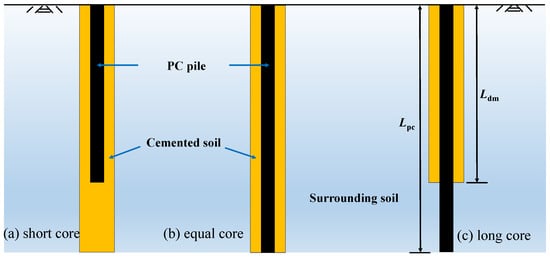
Figure 1.
Schematic diagram of the SDM column.
2.1. Interface Properties
The SDM column has two interfaces, i.e., the inner–outer core interface and the pile–soil interface, whose characteristics are the main factors controlling the bearing and deformation characteristics of this composite pile. The driving inner core can compress and expand the cemented soil and surrounding soil to make the pile–soil interface rougher and tighter, increasing the interface friction resistance of the SDM column []. Using field vertical tensile capacity tests, Jamsawang et al. [] illustrated that the interfacial shear strength can ensure that inner and outer cores do not misalign and slip. In addition, the interface damage mode changed from plastic damage to brittle damage with the increase in the unconfined compressive strength of the cemented soil. Test results indicated that the cored pile and cemented soil have good synergistic working characteristics, and ultimate interface resistance varies approximately linearly with the cemented soil strength []. Table 1 summarizes the ratio of friction resistance at the inner–outer core interface and the cemented soil strength in existing references. It can be seen that the range of the interfacial strength of the inner–outer cores of the SDM column differs greatly in the relevant Chinese codes.

Table 1.
The ratio of friction resistance at the inner–outer core interface and the cemented-soil strength.
2.2. Vertical Bearing Characteristics of the SDM Column
In recent years, many scholars have studied the vertical bearing characteristics of the SDM column using indoor model tests, field tests, and numerical simulations. Liu et al. [] studied the load transfer mechanism of the SDM column through full-scale model tests, with the results indicating that the deformation of the inner and outer cores is approximately coordinated under a vertical load. Furthermore, the axial force ratio of inner and outer cores in the same section is approximately equivalent to the ratio of their elastic modulus. Wang et al. [] found that the SDM column exhibited the working characteristics of a friction pile, and its vertical load was borne mainly by the lateral frictional force of the pile. Zhou et al. [,] concluded that inner and outer cores can be entirely taken into account in analyses of the vertical bearing characteristics of the SDM column. Wonglert et al. [] and Voottipruex et al. [] studied the bearing behavior and failure mode of the SDM column by performing model tests and numerical simulations. It was found that when the core length ratio exceeded the optimum value, the failure of the SDM column was mainly attributed to the plastic damage of the surrounding soil, i.e., the pile body sank entirely, and the various failure nodes were summarized based on the numerical results, as shown in Figure 2.
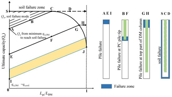
Figure 2.
The relationship between the core length ratio and ultimate capacity, as well as the associated failure modes [].
Regarding theoretical analysis, Gu et al. [] derived a theoretical method for calculating the axial stress and interface shear stress of the inner core of the SDM column based on the principle of composite mechanics and Mindlin’s solution. However, this method was limited to elastic analyses. Based on the load transfer method, Ren et al. [] proposed a simplified calculation method for the load transfer of the SDM column, considering inner–outer core and pile–soil interface friction, whilst ignoring the continuity of the surrounding soil. In addition, the corresponding calculation process involved complicated iterative trial calculations. Wang et al. [] developed a simplified approach for the axial response analysis of SDM column reinforcement embedded in non-homogeneous soil considering elastic non-slippage and elastoplastic slippage at the cemented soil–soil interface, and the increase in the strength and stiffness of subsoil with depth, as shown in Figure 3. Based on the deformation model of the surrounding soil, cemented soil, and the composite pile, Ye et al. [] proposed an analytical solution for calculating the stress ratio between the inner core, outer core, and the surrounding soil in the SDM column composite foundation under a rigid load. The predicted results indicate that the pile–soil stress ratio gradually increases with the diameter of the inner core and the length of DM column. According to the model test results, Li [] classified the failure modes of three modes of SDM columns with a short core, equal core, and long core. Among these, SDM columns with a short core include four modes, i.e., overall pile sinking, cross-sectional failure of the composite section, core pile piercing, and cross-sectional failure of the non-composite section. SDM columns with an equal core and long core will result in three failure modes, namely, overall pile sinking, cross-sectional damage of the composite section, and core pile piercing.
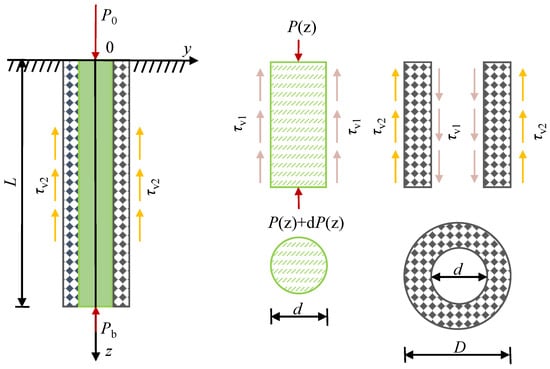
Figure 3.
Force diagram of the SDM column under rigid loads [].
2.3. Horizontal Bearing Characteristics of the SDM Column
In projects such as high embankments, ports, pits, and slope supports, pile foundations are subjected to both vertical and horizontal loads. Similarly, research on horizontal load-bearing characteristics of the SDM column has been conducted. Based on field tests and numerical simulation results, Voottipruex et al. [] found that the horizontal ultimate bearing capacity of the SDM column is approximately 10 times that of a DM column with the same parameters. Liu [] concluded that the bearing characteristics of the SDM column under a horizontal load are similar to those of the PC pile. However, the presence of the outer core can effectively reduce the maximum bending moment and shear force of the inner core, as well as enhance the pile head stiffness. Wang et al. [] reported that the horizontal ultimate bearing capacity of this composite pile formed by bored piles constructed in jet-grouted piles can be increased by 64–69% compared with bored piles with the same parameters. He et al. [,] systematically evaluated the effect of using jet-grouted pile reinforcement on the horizontal force performance of bored piles in a soft clay. The results showed that the jet-grouted reinforcement could significantly improve the pile head stiffness, and reduce the cumulative displacement of the bored piles under static loads and one-way and two-way cyclic loads. Based on the comparative analysis of the horizontal bearing behaviors of the SDM column and PHC pile using numerical simulations, Du et al. [] concluded that the horizontal displacement and bending moment of the SDM column were significantly lower than those of the PHC pile under the same horizontal load.
Concerning the theoretical calculation of the horizontal bearing capacity of composite piles, Huang et al. [] proposed the calculation method of the proportional coefficient, m, of the horizontal resistance coefficient of the SDM column. The results showed that flexural stiffness of the horizontal bearing capacity calculated by the m method should be taken as the algebraic sum of the inner core and outer core, where the m value of the SDM column is closer to that of the bored pile recommended by the Technical Code for Building Pile Foundations (JGJ 94-2008) []. By considering the contribution of the DM column, Li et al. [] derived the formula for calculating the horizontal bearing capacity of the SDM column using the modified m approach, and the range of m values and influencing factors were discussed.
2.4. Status of Research on the SDM Column-Supported Embankment
To further improve the application of the SDM column-supported embankment reinforcement on soft soil, researchers have studied the load transfer mechanism, consolidation characteristics, embankment stability, and settlement calculation of the SDM column composite foundation under embankment loads. To examine the load-bearing characteristics, Zhang et al. [] performed a series of centrifuge model tests and numerical analysis to study the pile–soil load transfer mechanism and consolidation characteristics of the SDM column-supported embankments with a slab on soft soil, as shown in Figure 4. The results showed that the slab above the gravel cushion effectively reduced differential settlement, accelerated subsoil consolidation, and improved the load-bearing ratio of the SDM column. When the core length ratio falls within the range of 0.5 to 0.8, it ensures high load transfer efficiency between the pile and soil, while causing stress concentrations in the slab and inner core under load. Ye et al. [] found that the soil arching heights of the SDM column-supported embankment are 1.7 and 1.3 times the net spacing of inner cores according to the soil stress and deformation control conditions, respectively. Thus, it is proposed that the embankment height should be 1.5 times the soil arching height, and the area replacement rate of inner cores should be within the range of 13–25% during engineering design after conducting a multi-parameter analysis. Regarding the calculation of embankment settlement, Ye et al. [] proposed a method of settlement calculation for SDM column-supported embankments over soft soil considering the core pile piercing the outer core. The total settlement comprised three parts: soil settlement within the length of the inner core, soil settlement from the inner core tip to the tip of the SDM column, and soil settlement below the bottom of the SDM column. A case analysis revealed that the results of the proposed calculation model are in better agreement with the embankment settlement determined from measurements.
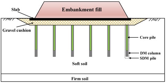
Figure 4.
Schematic diagram of SDM column-supported embankment on soft soil [].
The consolidation of soft soil is a key issue affecting the settlement of the embankment. Based on the assumption of a constant stress concentration ratio during the consolidation, Zhang et al. [] proposed an analytical model of consolidation for the SDM column-supported embankment without considering pile–soil interaction, as shown in Figure 5. Compared to a pure DM column, the existence of the PC pile in the DM column significantly reduced the maximum excess pore water pressure induced by embankment loads, which was attributed to the core pile playing a significant role in load shear due to its high modulus. Yang et al. [] derived the consolidation equations for SDM columns (floating long core, penetrated long core, and short core) composite foundations. Subsequently, the analytical solutions for the excess pore water pressure and the overall average consolidation degree of the SDM column composite foundation for the surrounding soil and underlying stratum were established. The results indicate that the consolidation rate increases with the penetration ratio of the pile and the compression modulus of the underlying stratum for the floating long-core SDM column composite foundation. However, the length and stiffness of the outer core do not affect the consolidation rate. The consolidation rate increases with an increasing compression modulus for the SDM column composite foundations with a long core []. Regarding the SDM column composite foundation with a short core, the consolidation rate increases with the replacement ratio of this composite pile, the core length ratio, and the cemented soil compression modulus under a variable load []. However, the aforementioned solutions do not consider the pile pierced into the gravel cushion and the additional stress that varies with time and depth. Zhang et al. [] developed an analytical solution for the consolidation of the composite ground reinforced by SDM columns based on a modified equal strain assumption.
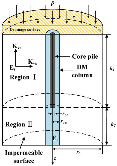
Figure 5.
Analytical consolidation model of the SDM column-supported embankment [].
The main function of the SDM column is to transfer the embankment loads to the subsoils, thus reducing settlement through the arching effect. The SDM column also plays a crucial role of increasing the slope stability against horizontal or sliding forces under embankment loads. Zhang et al. [] conducted scale-down 1g (normal gravity) model tests to illustrate the failure mechanism of the SDM column-supported embankment. The results show that the SDM columns under the embankment firstly failed by compression with local bulging of the inner core bottom, followed by the sequence bending failures of the columns below the embankment slope subjected to the horizontal force of the soil. The sliding surface of the foundation was not completely through the pile damage location. In addition, the sequence and modes of the columns’ failure, as well as the load transfer obtained from the indoor tests, were verified by the numerical analysis considering the strain softening of the SDM column. It was concluded that the progressive failure mechanism of the SDM column-supported embankment is due to the strain softening of the material and the uneven distribution of additional stresses []. In addition, due to the lack of a technical code for the calculation of the safety factor of the embankment supported by SDM columns, Zhang et al. [] adopted the semi-rigid column method based on residual strength in the currently used code. This yielded a close safety factor for the tested results, although its feasibility still needs further study.
Combined with existing findings, the SDM column is currently widely employed in industrial and civil construction engineering. Nonetheless, its applications in the fields of highways and railways have been limited because the force form of the SDM column composite foundation under flexible loads is different from that under rigid loads. The existing research mainly concentrates on the load transfer mechanism, the settlement calculation, and the consolidation of the SDM column-supported embankment with the rigid slab. However, there have been few systematic studies of stability calculations, consolidation characteristics, and the seismic performance of this type of column-supported embankment.
3. Status of Research on Variable-Section Pile Technology
Most recent ground treatment and pile foundation engineering has involved the use of the piles with equal sections. However, the conventional equal-section piles often fail to consider the pile tip resistance and lateral friction resistance, resulting in certain limitations for deep and weak soil treatment; in addition, piled foundation engineering requires high bearing capacity and strict settlement control. Piles with a variable section, such as squeezed branch piles and PGPN piles, have been improved compared to traditional piles by enhancement of the frictional properties of the pile–soil interface and the expanded head at the pile tip []. This enhancement leads to an improved pile-end bearing performance, allowing for the full mobilization of the bearing capacity of the surrounding soil and effectively increasing the bearing capacity of the single pile, as well as meeting the requirements of complex projects [,]. In particular, the stratum often appears to be layered due to deposition, indicating a stratified distribution of soft soil and medium compressible soil. If the conventional equal-section piles are adopted to reinforce this kind of layered soft ground, the design leads to a high replacement rate of piles in medium compressible soil layers, which leads to resource waste and increases the cost of the projects. For such a situation, bi-directional mixing technology using automatic expanding blades (see Figure 6) enables the realization of the variable-section mixing pile. This variable-section mixing pile (shown in Figure 7) optimizes the vertical stiffness for layered foundations, forming a layered composite foundation in which the replacement rate varies with the nature of the soil layer, and realizing a cost-effective treatment of layered foundations []. To date, three kinds of piles with variable sections, namely, the squeezed branch pile, PGPN pile, and variable-section deep mixing (VDM) column, have been widely studied and applied in coastal regions because of their superior engineering properties.
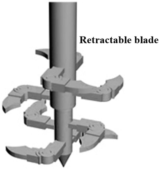
Figure 6.
Schematic of the automatic retractable mixing blade.
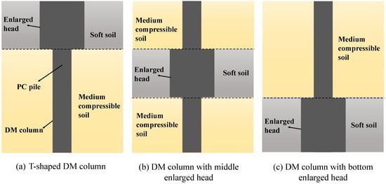
Figure 7.
Schematic diagram of VDM columns reinforcing layer-forming soft ground.
3.1. Squeezed Branch Pile Technology
The squeezed branch pile (shown in Figure 8) is a novel variable-section pile that features multiple enlarged parts at specific locations along the bored pile shaft, designed according to the distribution of soil strata. Compared with conventional bored piles, it can significantly improve the vertical bearing capacity and pull-out resistance []. Since the 1990s, this pile type has been widely used in foundation engineering in China. Subsequently, the compressive, pullout, horizontal, and seismic performances of the squeezed branch piles have been extensively studied.
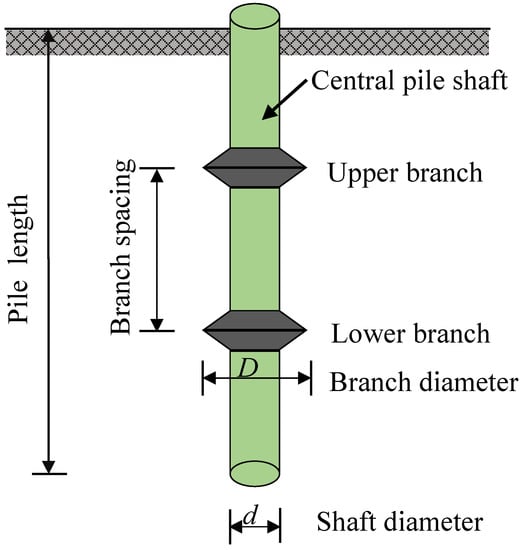
Figure 8.
Schematic diagram of the squeezed branch pile.
The effect of compressive behaviors on the bearing mechanism [,], the calculation of the bearing capacity [,], and the optimization of parameters [,,,] of the squeezed branch pile have been extensively studied using laboratory model tests, numerical analyses, and field tests. Yang et al. [,] found that the pile lateral friction resistance and the branch resistance have an obvious time sequence effect, and the friction resistance occurs before the plate. Zhang et al. [] indicated that the displacement field of both the branch and the pile tip had a radial shape, and to reduce the negative effect of soil displacement on the frictional resistance at the interface under the branches, it was proposed that the branch spacing exceeds three times the diameter of the branch. Concerning the theoretical calculation of bearing capacity and settlement, Li et al. [] proposed a simplified nonlinear method for calculating the bearing capacity and settlement of the squeezed branch pile using a hyperbolic model and applying a segmental displacement coordinated iterative algorithm, which was verified by the measured results in field tests. Gao et al. [] proposed a method for calculating the horizontal bearing capacity of the squeezed branch pile; its results were in good agreement with the numerical results. When the squeezed branch pile is used to support foundation pits, its maximum bending moment and axial force are reduced by 20–60% compared with the traditional cantilever support, and the overturning moment provided by the branches can effectively improve the bending resistance of the squeezed branch pile [].
Unlike ordinary uplift piles, whose bearing capacity is contributed by the lateral frictional resistance and the pile’s self-weight, the presence of the branches can effectively provide the tip load, thus effectively increasing its extracted load capacity []. The load transfer process of the squeezed branch pile is gradually exerted from the lateral frictional resistance of the pile shaft to each branch. During the damage process, the plastic zone at the branch initially appears and then gradually develops into the damage surface as the uplift load increases, caused by the pile–soil sliding []. By fitting the load-deformation curves of 22 squeezed branch piles obtained from the field tests using the modified hyperbolic model, Jiang et al. [] found that the calculated uplift loads of the fitted curves were in agreement with the measured values. In addition, the tensile strength provided by the unit pile length of the squeezed branch pile was 7.5% higher than that of the straight pile in clayey strata [].
3.2. Pre-Bored Grouting Planted Nodular (PGPN) Pile
Since its emergence, the pre-bored grouting planted nodular (PGPN) pile has attracted significant attention from scholars at home and abroad. This pile is formed by inserting a precast nodular pile and cemented soil using the static drilling and rooting method, as shown in Figure 9. Numerous studies of its compressive [,] and pullout-bearing characteristics [,] have been carried out. Kiya et al. [] analyzed the effect of the size and shape of the enlarged base on the bearing performance of the PGPN pile by conducting experimental tests, and they concluded that increasing the diameter and height of the enlarged head could significantly improve the bearing capacity of the PGPN pile. Karkee et al. [] proposed a reliability-based model for calculating the ultimate bearing capacity of PGPN piles with 95% confidence based on the field loading tests of PGPN piles with a pile top displacement of 13 mm. Hirai [] studied the compressive bearing characteristics of a piled raft with PGPN piles using a Winkler model approach. The theoretical relationship between the pile-end bearing capacity and the displacement was established.
In addition, the vertical stiffness coefficients in non-homogeneous soil have been determined. Professor Gong’s group systematically studied the compressive, pullout, and horizontal bearing characteristics of PGPN piles in soft soil, which included the load transfer mechanism [,,], the calculation method of settlement and load carrying capacity [,,], the influence of key parameters [,,,], and the longitudinal dynamic properties [,,,,]. Field static loading tests revealed that the bearing capacity of PGPN piles exceeds that of ordinary bored piles, whose displacement is controlled by the precast pile, and the lateral friction resistance is 1.05–1.10 times that of bored piles []. To address the problem of the low strength of the bearing layer, sand filling can effectively improve the soil properties around the PGPN pile and the frictional behavior of the pile–soil interface; the pile shaft resistance coefficient can then reach values of 1.15–1.40 []. Based on the results of laboratory model tests, Zhou et al. [] verified that the pile tip displacement of the PGPN pile can be calculated using the theoretical method of the conventional pile.

Figure 9.
Schematic diagram of the PGPN pile [].
Numerical analysis shows that the compressive characteristics of the PGPN pile are better than the pullout characteristics. The cemented soil in the non-expanded section of a PGPN pile only transforms the shear stress, but does not bear the load, and the proportion of the total tip resistance of the precast pile is smaller than that borne by the enlarged base of the cemented soil []. The total lateral friction reduction factor (λ) was defined as the ratio of the shaft resistance between the uplift pile and the compressive pile, and it was found that λ does not vary with the enlarged base diameter [].
3.3. Variable-Section Composite Pile Technology
The construction technology, mechanism, and design method of the VDM column have been developed and have matured. However, due to the limited strength of cemented soil, it is difficult for the VDM column to meet the requirements of high bearing capacity and strict settlement control for deep soft soil ground treatment. The idea of a novel composite pile, termed the precast cement pile reinforced by cemented soil with a variable section (PCCV), which is formed by inserting a PC pile into a VDM column, can effectively solve the problem of the insufficient bearing capacity of the VDM column [], as shown in Figure 10. PCCVs can be divided into three types of piles having top, middle, and bottom enlarged heads according to the location of the variable section. Among these, the replacement rate of the DM column varies with the mechanical properties of the soil layer, which can ensure that the PCCV has a high bearing capacity and can reduce resource use and project costs, reflecting the concepts of efficient energy saving and environmental ground treatment.
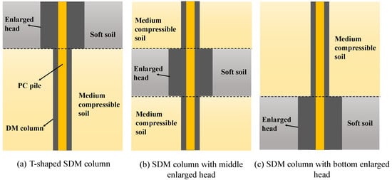
Figure 10.
Schematic diagram of the PCCV.
4. Status of Research on Low-Carbon Energy-Saving Reinforcement Technologies
Traditionally, Portland cement has been used as the main curing material for ground improvement and piling works. However, cement-based curing agents cannot be adapted to the needs of low-carbon green engineering construction, with the main problems being: ① Significant consumption of resources and energy: the calcination temperature during cement production is about 1450 °C, which requires a large amount of energy [,]. In China, for example, each ton of cement clinker produced requires an average consumption of 0.95 tons of limestone, 0.13 tons of clay, and 0.11 tons of standard coal, and it is an irreversible process [,]. China’s limestone resources can last for about 35–40 years. ② Serious CO2 emissions and air pollution: the production of 1 ton of cement emits about 0.85 tons of CO2, and the cement industry is one of the main sources of anthropogenic CO2 emissions. ③ Cement production also emits large amounts of dust, soot, and toxic gases, such as sulfur dioxide, nitrogen oxides, and fluorine gas, causing significant environmental pollution. ④ Cement-cured soils react more slowly, generally requiring 28 days of maintenance before they can be carried [,].
For this reason, in recent years, studies concerning new low-carbon and energy-saving curing agents have become a focus of research in the field of engineering. New curing materials, such as reused industrial waste and magnesium oxide cement, have been studied and applied.
4.1. Status of Research on Industrial Solid Waste Curing Technology
With rapid modern industrialization, the generation of a large amount of industrial waste residue can result in environmental pollution and resource waste if the waste is not effectively treated in a timely manner. In recent years, the use of alkali-activated binding materials, as new environmentally friendly curing agents, has attracted extensive attention worldwide []. Alkali-activated binding materials use an alkaline activator to activate industrial by-products/waste with cementing components, resulting in common industrial by-products such as blast furnace slag, fly ash, phosphate slag, steel slag, and silicon powder. Among these, blast furnace slag and fly ash have been more widely researched and are considered mature binding materials due to their more stable and excellent performance [,].
- (1)
- Blast furnace slag
In the 1940s, researchers began to focus on alkali-activated binding materials, studying the binding properties of blast furnace slag after activation of KOH and NaOH [,]. However, to increase the activity of blast furnace slag, which is low at room temperature, the slag is water quenched and finely ground to obtain ground granulated blast furnace slag (GGBS), which has been widely used due to its desirable properties [,]. The current activators for GGBS include NaOH, Na2CO3, Na2SO4, lime, and MgO. Yi et al. [] found that the activation effect of Na2CO3 on a GGBS–soil admixture was very limited, while NaOH had the best activation effect on a GGBS–soil admixture, with the highest strength at different ages among the aforementioned four activators. Furthermore, lime has been used as an activator of GGBS for soft soil subgrade improvement, non-sintered bricks, and clay stabilization [,,,]. In addition, the micro-mechanism [,], strength characteristics, and durability [,] of lime-activated GGBS–soil admixtures have been systematically studied. The results show that lime-activated GGBS can effectively reduce the swelling characteristic of the soil, because of its higher unconfined compressive strength and better durability, which can better mitigate the adverse effects of flooding on the embankment than cement-activated GGBS soil.
As part of the continuous research into the GGBS activated by alkaline materials, Liu et al. presented a series of studies of soft soil treatment with active MgO as the activation material of GGBS, investigating the action mechanism [,,], microstructure, strength properties [], acid resistance, and durability [,,]. The results indicate that the effect of MgO-activated GGBS is significantly better than that of lime-activated GGBS, and that the strength of GGBS-MgO reinforced soil can exceed that of Portland cemented soil with the same dosage. Micromechanical analysis revealed that calcium silicate hydrate (CSH) is the main hydration product of both MgO–GGBS and lime–GGBS; the latter can effectively encapsulate and connect the soil particles, whereas the former can produce more hydrotalcite to fill the pores, thus explaining the main reason for the superior strength of MgO–GGBS over GGBS–lime and Portland cement (PC).
- (2)
- Fly ash
Fly ash is a common component of cement and concrete and is widely used in projects such as railway bridges, highway pavements, and dams. Research has revealed that mixing various activators such as lime, cement, and MgO with fly ash can be used as fly-ash-based cementitious materials. At the end of the 1990s, preliminary investigations into the strength properties, reaction mechanism, and microstructure of cement and fly-ash-solidified clay were performed [,,]. Nalbantoğlu et al. [] found that fly ash can effectively reduce the swelling of highly plastic clay. Kolias et al. [] performed a microscopic analysis of high-calcium fly ash and cement-solidified silty clay, and found that cement can provide an alkaline environment for the reaction, and can thus promote the formation of fly ash into calcium silicate hydrate. Among the continuous research into fly-ash-solidified soft soil technology, extensive research on the performance of different types of activators to excite fly-ash-cured soft soil has been carried out. The activations studied in more detail include NaOH, Na2CO3, and Na2SiO3·9H2O, as well as active MgO. It has been shown that the first three of these activators can effectively excite fly ash–sludge admixtures by improving their unconfined compressive strength, and that NaOH and Na2SiO3·H2O are more effective than Na2CO3. Furthermore, the whole process model of the sludge improvement induced by the intrinsic chemical reaction of alkali-activated fly ash has been established.
Concerning MgO-activated fly-ash-cured soft soils, Professor Wang’s team carried out a series of studies of the microscopic mechanism [,], strength properties [,,], and durability [,,] of stabilized dredged sludge. X-ray diffraction analysis and scanning electron microscopy indicated that MgO-activated fly ash could generate cementation products, Mg(OH)2 and magnesium silicate hydrate (M-S-H), which transformed the intra-granular pores into inter-particle pores and promoted the microstructure of soft soils to be denser and more integral. The whole process model of stabilized silt induced by the intrinsic chemical reaction of reactive MgO-fly ash was established. In addition, the results of the durability tests showed that the reactive MgO-fly ash stabilization method could effectively enhance the freeze–thaw resistance and water stability of the sludge. In addition, after 10 freeze–thaw cycles, the surface of the specimens did not show significant cracks.
4.2. Research Status of Magnesium Oxide Curing Technology
In 2001, based on the concept of environmental protection, Harrison [,] was the first to invent a new curing material by mixing active magnesium oxide (MgO) and Portland cement. Compared with conventional PC, the MgO mixture, which has a lower calcination temperature, can absorb a large amount of CO2 gas during the hydration process, and the hydrated magnesium carbonates generated by the reaction have better curing strength, durability, carbonation resistance, and salt resistance, as shown in Figure 11. Moreover, the hydrated magnesium carbonates can re-generate MgO after calcination, which realizes the recycling of resources and effectively reduces the emission of greenhouse gases. Figure 11 shows the schematic diagram of the cycle of MgO and CO2.
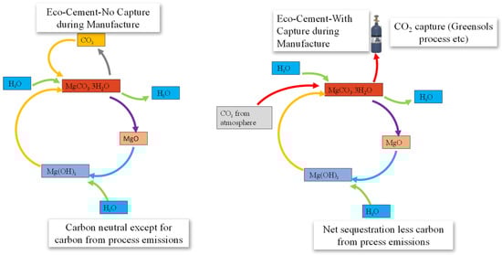
Figure 11.
Schematic diagram of MgO and CO2 cycles [].
Subsequently, Professor Al-Tabbaa’s group at the University of Cambridge conducted a detailed study of reactive MgO cements, including of their hydration properties [,], microstructure [], carbonation properties [,], and applications of building blocks []. It was shown that the hydration process of activated MgO–PC blended cement proceeds independently to produce Mg(OH)2 and hydrated magnesium silicate. In addition, the former has low cementitious strength and the involvement of activated MgO does not contribute to the mechanical properties of the cement. However, the strength of blocks using independent activated MgO as a binding agent was 2–3 times that of PC blocks under the forced carbonation with a CO2 concentration of 20%, which produces hydrated magnesium carbonate with high cementitious strength due to the carbonation of MgO. Based on the results of acid resistance and corrosion resistance tests, it was found that the carbonized blocks were more resistant to sulfuric acid than PC blocks; however, they were less resistant to hydrochloric acid erosion than PC blocks [,].
On the basis of the successful application of magnesium oxide in building masonry, Professor Liu first proposed the soft soil ground treatment reinforced by active MgO under forced carbonation. The micro-mechanisms, freeze–thaw cycles [,,,], permeability [,], resistivity [,,], and acid resistance [] of different types of soft soils, including sandy, silt, and clayey soils treated with active MgO, were investigated. Laboratory experiments, microscopic tests, and model tests were used to systematically analyze the effects of crucial parameters, such as MgO dosage, carbonization time, initial moisture content, MgO activity index, CO2 pressure, and compaction degree, on the performance of carbonized soil []. The critical dosage of MgO (20–25%), the critical carbonation time (8–10 h), the prediction equation of the carbonation strength, and the prediction model of the resistivity of carbonated soil were obtained. Based on the above research results and in response to the problems with respect to field application, Professor Liu et al. [,,] proposed deep MgO mixing (DMM) column technology using active MgO as an alternative to PC under CO2 gas at a specific pressure to carbonize the mixing soil for ground treatment.
The chemical reaction between MgO, water, and CO2 can rapidly reduce the water content and the porosity of soil, and increase the cementation strength. The results of indoor model tests indicate that the strength of deep MgO mixing (DMM) columns decreased exponentially with the increasing initial water content, and conversely increased with the CO2 pressure []. Yi et al. [] concluded that the DMM column still has considerable unconfined compressive strength with low MgO content in soft soil. In addition, the time required for carbonation reactions is significantly less than the 28 days curing time required for conventional cement curing.
However, the complex DMM column method under forced CO2 carbonation fails to ensure good agreement with the original approach. The CO2 gas tends to flow upward, thus affecting the uniformity of the DMM column and resulting in a limited depth of soft ground treatment. To address these problems, Liu et al. [] first proposed the carbonized composite pile (CCP), which is typically formed by inserting a pervious concrete pile into a DMM column, after the construction of the DMM column, as shown in Figure 12. The advantage of this method is that the CO2 gas can enter and react with the soil–MgO mixture through the pervious concrete pile, where the uniformly distributed gas outlet channels can promote a more uniform carbonization effect of the DMM column. Wang [] proved that the carbonation strength using this carbonization method can reach that obtained from triaxial compression tests under constant conditions.
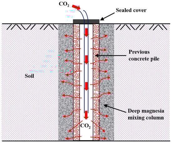
Figure 12.
Schematic diagram of the carbonized composite pile.
The research described above reveals that reducing the amount of cement or using low-carbon materials to replace cement is the current goal of the engineering community globally, and significant progress has been made in recent years. In particular, the reinforcement mechanism and effect of industrial waste utilization and MgO carbonization technologies have been clarified, and these technologies have been successfully applied in engineering practice. It is still necessary to identify methods for further enhancing the combination of low-carbon curing materials and engineering applications, study their mechanism of action and effects, and establish practical engineering design and analysis methods. In addition, it is necessary to better understand the requirements of low-carbon sustainable development strategies. Table 2 summarizes the characteristics of various efficient and low-carbon pile technologies, including the depth, cross-section type, and technical maturity, which can provide some suggestions for engineering practice.
Table 2.
The characteristics of various efficient and low-carbon pile technologies.
5. Conclusions
This paper reviews and summarizes the current research status and practical applications of efficient and low-carbon pile technologies in deep soft soil strata, including the SDM column, the squeezed branch piles, the PGPN pile, the PCCV piles, and the CCP, as well as several low-carbon and energy-saving curing agents. Thus, this review may be helpful for overcoming the technical bottleneck of deep and weak soil foundation treatment, and promoting low-carbon environmental protection and sustainable development of foundation treatment technology. The conclusions that can be drawn are as follows:
- (1)
- The interfacial mechanical properties, and horizontal and vertical bearing properties, of the SDM column, as well as the bearing mechanism and failure mode of the SDM column-supported embankment, have been systematically analyzed. Studies of stability calculations, consolidation characteristics, and the seismic performance of this column-supported embankment need to be conducted in further research.
- (2)
- Squeezed branch piles, PGPN piles, and PCCV piles, which are variable-section piles, have significant advantages for the layered strata because they adopt an optimal replacement ratio of branches or enlarged heads to effectively improve the bearing capacity. Compared to traditional piles, their enhancements have been achieved by increasing the frictional properties of the pile–soil interface and the expanded head to fully mobilize the bearing capacity of the surrounding soil.
- (3)
- The low-carbon curing agents of pile materials widely used for soft soil stabilization can provide a solution for novel piles, whose application in engineering is insufficient. In addition, determining how to further enhance the combination of low-carbon curing agents and existing pile technologies, studying their mechanism of action and effects, and establishing practical engineering design and analysis methods remain to be addressed.
Author Contributions
Conceptualization, C.Z., S.L. and J.H.; methodology, J.H. and C.J.; investigation, C.Z. and J.H.; resources, Z.C., C.J., X.D. and G.C.; writing—original draft preparation, C.Z.; writing—review and editing, J.H. and L.T.; visualization, S.L. and Z.C.; supervision, S.L. and L.T.; funding acquisition, S.L., Z.C., C.J. and G.C. All authors have read and agreed to the published version of the manuscript.
Funding
This research work is supported by the National Natural Science Foundation of China (No. 52078129 & 42277146),the Transportation Science and Technology Project of Jiangsu Province of China, the Introduction Program of High-Level Innovation and Entrepreneurship Talents in Jiangsu Province (No. JSSCBS20210385) and the Natural science research project of colleges and universities of Jiangsu Province (No. 21KJB170019).
Data Availability Statement
Not applicable.
Acknowledgments
All of these financial supports are gratefully acknowledged. The authors also wish to thank Southeast University for providing the access to the software and other facilities.
Conflicts of Interest
No potential conflict of interest was reported by the authors.
Nomenclature
| CCP | Carbonized composite pile |
| CSH | Calcium silicate hydrate |
| DM | Deep mixing |
| DMM | Deep MgO mixing |
| Dpc/Ddm | Core diameter ratio |
| GGBS | Ground granulated blast furnace slag |
| Lpc/Ldm | core length ratio |
| m | Proportional coefficient of the horizontal resistance coefficient |
| PC | Precast concrete |
| PCCV | Precast cement pile reinforced by cemented soil with variable section |
| PGPN | Pre-bored grouting plated nodular |
| PHC | Pre-stressed high-strength concrete |
| SDM | Stiffened deep mixing |
| TDM | T-shaped deep mixing |
| VDM | Variable-section deep mixing |
References
- Lai, F.; Yang, D.; Liu, S.; Zhang, H.; Cheng, Y. Towards an improved analytical framework to estimate active earth pressure in narrow c–ϕ soils behind rotating walls about the base. Comput. Geotech. 2022, 141, 104544. [Google Scholar] [CrossRef]
- Wang, X.; Shen, L.; Shi, S. Evaluation of underground space perception: A user-perspective investigation. Tunn. Undergr. Space Tech. 2023, 131, 104822. [Google Scholar] [CrossRef]
- Wang, X.; Li, S.; Xu, Z.; Li, X.; Lin, P.; Lin, C. An interval risk assessment method and management of water inflow and inrush in course of karst tunnel excavation. Tunn. Undergr. Space Tech. 2019, 92, 103033. [Google Scholar] [CrossRef]
- Wu, W.; Zhang, Y. A Review of Pile Foundations in Viscoelastic Medium: Dynamic Analysis and Wave Propagation Modeling. Energies 2022, 15, 9432. [Google Scholar] [CrossRef]
- Liu, H. Study on green ground improvement technique. China Civ. Eng. J. 2018, 51, 121–128. [Google Scholar]
- Liu, S.; Zhou, J.; Zhang, D. State of the art of the ground improvement technology in China. China Civ. Eng. J. 2020, 53, 94–110. [Google Scholar]
- Zheng, G.; Long, X.; Xie, Y. State-of-the-art techniques for ground improvement in China. China Civ. Eng. J. 2012, 45, 127–146. [Google Scholar]
- Behnood, A. Soil and clay stabilization with calcium- and non-calcium-based additives: A state-of-the-art review of challenges, approaches and techniques. Transp. Geotech. 2018, 17, 14–32. [Google Scholar] [CrossRef]
- Gomes Correia, A.; Winter, M.G.; Puppala, A.J. A review of sustainable approaches in transport infrastructure geotechnics. Transp. Geotech. 2016, 7, 21–28. [Google Scholar] [CrossRef]
- GB/T 50783-2012; Techniacl Code for Composite Foundation. Ministry of Housing and Urban-Rural Development of the People’s Republic of China, China Planning Press: Beijing, China, 2012.
- Dai, X.; Zheng, G.; Zhang, N. Seismic performance of PHC pipe piles of high-rise building in layered soft soils. China Civ. Eng. J. 2019, 52, 248–256. [Google Scholar]
- Zheng, G.; Zhang, N.; Ba, Z. Seismic performance of PHC pipe piles in layered soft soils. Chin. J. Geotech. Eng. 2013, 35, 506–510. [Google Scholar]
- JGJ/T 327-2014; Techinal Specification for Strength Composite Piles. Ministry of Housing and Urban-Rural Development of the People’s Republic of China, China Architecture & Building Press: Beijing, China, 2014.
- Xiao, H.; Luo, Q.; Deng, J. Test study of reinforcing railway subgrades by using concrete compacted base-enlarged piles and geogrids. Rock Soil Mech. 2008, 29, 2157–2162. [Google Scholar]
- Ye, G.; Cai, Y.; Zhang, Z. Research on calculation of pile-soil stress ratio for composite foundation reinforced by stiffened deep mixed piles. Rock Soil Mech. 2016, 37, 672–678. [Google Scholar]
- Li, J.; Zhang, Y.; Deng, Y. Load transfer mechanism of composite pile composed of jet-mixing cement and phc pile with core concrete. Chin. J. Rock Mech. Eng. 2014, 33, 3068–3076. [Google Scholar]
- Qian, Y.; Xu, Z.; Deng, Y. Engineering application and test analysis of strength composite piles. Chin. J. Geotech. Eng. 2013, 35, 998–1001. [Google Scholar]
- Li, J.; Deng, Y.; Song, G. Analysis of load-bearing mechanism of composite foundation of plain concrete reinforced ce-ment-soil mixing piles. Rock Soil Mech. 2009, 30, 181–185. [Google Scholar]
- Liu, S. Innovative Deep Mixing Method–Theory and Technology; Southeast University Press: Nanjing, China, 2014. [Google Scholar]
- Liu, S.; Du, Y.; Yi, Y.; Puppala, A.J. Field Investigations on Performance of T-Shaped Deep Mixed Soil Cement Column–Supported Embankments over Soft Ground. J. Geotech. Geoenviron. 2012, 138, 718–727. [Google Scholar] [CrossRef]
- Yi, Y.; Liu, S.; Puppala, A.J. Laboratory modelling of T-shaped soil–cement column for soft ground treatment under embankment. Géotechnique 2015, 66, 85–89. [Google Scholar] [CrossRef]
- Li, L.; Cheng, X. Load Transfer Method for Squeezed and Branch Piles Considering Cavity Esspansion Theory. China J. Highw. Transp. 2018, 31, 20–29. [Google Scholar]
- Lu, C.; Jia, Y.; Zhou, L. Project performance study of model piles with branches and plates under repeated load in silty clay. Rock Soil Mech. 2008, 29, 431–436. [Google Scholar]
- Li, M.; Cai, G.; Wang, Q.; Liu, S.; He, H.; Liu, X.; Shi, W. The state of the art of carbonation technology in geotechnical engineering: A comprehensive review. Renew. Sustain. Energy Rev. 2023, 171, 112986. [Google Scholar] [CrossRef]
- Yi, Y.; Liska, M.; Jin, F.; Al-Tabbaa, A. Mechanism of reactive magnesia–ground granulated blastfurnace slag (GGBS) soil stabilization. Can. Geotech. J. 2016, 53, 773–782. [Google Scholar] [CrossRef]
- Yi, Y.; Liska, M.; Al-Tabbaa, A. Properties and microstructure of GGBS–magnesia pastes. Adv. Cem. Res. 2014, 26, 114–122. [Google Scholar] [CrossRef]
- Yi, Y.; Gu, L.; Liu, S.; Jin, F. Magnesia reactivity on activating efficacy for ground granulated blastfurnace slag for soft clay stabilisation. Appl. Clay Sci. 2016, 126, 57–62. [Google Scholar] [CrossRef]
- Zhu, S.; Chen, C.; Cai, H.; Mao, F. Analytical modeling for the load-transfer behavior of stiffened deep cement mixing (SDCM) pile with rigid cap in layer soils. Comput. Geotech. 2022, 144, 104618. [Google Scholar] [CrossRef]
- Zhang, C.; Zhang, D.; Liu, S.; Han, J.; Jiang, C.; Zhao, Y. Analytical Solution for Consolidation Behaviors of Combined Composite Foundation Reinforced with Penetrated PCCSs and Floating DM Columns. Geofluids 2023, 2023, 7371850. [Google Scholar] [CrossRef]
- Zhang, C.; Liu, S.; Zhang, D.; Lai, F.; Lu, T.; Liu, Y. A modified equal-strain solution for consolidation behavior of composite foundation reinforced by precast concrete piles improved with cement-treated soil. Comput. Geotech. 2022, 150, 104905. [Google Scholar] [CrossRef]
- Zhou, M.; Li, Z.; Han, Y.; Ni, P.; Wang, Y. Experimental Study on the Vertical Bearing Capacity of Stiffened Deep Cement Mixing Piles. Int. J. Geomech. 2022, 22, 04022043. [Google Scholar] [CrossRef]
- Zhou, J.; Yu, J.; Gong, X.; El Naggar, M.H.; Zhang, R. The effect of cemented soil strength on the frictional capacity of precast concrete pile–cemented soil interface. Acta Geotech. 2020, 15, 3271–3282. [Google Scholar] [CrossRef]
- Li, L. Study on the Bearing Capacity of Stiffened DCM Pile; Southeast University: Nanjing, China, 2016. [Google Scholar]
- Han, Y.; Cheng, J.; Zhou, M.; Ni, P.; Wang, Y. Experimental Study of Compaction and Expansion Effects Caused by Penetration of Core Pile During Construction of SDCM Pile. Int. J. Geomech. 2022, 22, 04022041. [Google Scholar] [CrossRef]
- Wang, A.; Zhang, D.; Deng, Y. A Simplified Approach for Axial Response of Single Precast Concrete Piles in Cement-Treated Soil. Int. J. Civ. Eng. 2018, 16, 1491–1501. [Google Scholar] [CrossRef]
- Du, G.; Wang, A.; Li, L.; Zhang, D. Calculation Approach for Lateral Bearing Capacity of Single Precast Concrete Piles with Improved Soil Surrounds. Adv. Civ. Eng. 2018, 2018, 5127927. [Google Scholar] [CrossRef]
- Li, H.; Liu, S.; Tong, L. Field investigation of the performance of composite foundations reinforced by DCM-bored piles under lateral loads. Constr. Build. Mater. 2018, 170, 690–697. [Google Scholar] [CrossRef]
- Wang, A.; Zhang, D.; Deng, Y. Lateral response of single piles in cement-improved soil: Numerical and theoretical investigation. Comput. Geotech. 2018, 102, 164–178. [Google Scholar] [CrossRef]
- Jamsawang, P.; Bergado, D.T.; Voottipruex, P. Field behaviour of stiffened deep cement mixing piles. Proc. Inst. Civ. Eng.-Ground Improv. 2011, 164, 33–49. [Google Scholar] [CrossRef]
- Zhou, Z.; Lin, F. Design and construction reason of reinforced concrete cement-soil composite pile with strong core–New pile type used in soft soil foundation. Geotech. Eng. 2000, 12, 19–21. [Google Scholar]
- Wu, M.; Zhao, X. Bearing Behaviors of Stiffened Deep Cement Mixed Pile. Trans. Tianjin Univ. 2006, 12, 209–214. [Google Scholar]
- DBJ 53/T-19-2007; Technical Specification for Concrete Core Mixing Pile. Construction Department of Yunnan Province, Yunnan Science and Technology Press: Kunming, China, 2007.
- JGJ/T 330-2014; Technical Specification for Pile Foundation of Pipe Pile Embedded in Cement Soil. Ministry of Housing and Urban-Rural Development of the People’s Republic of China, China Architecture & Building Press: Beijing, China, 2014.
- Liu, H.; Ren, L.; Zheng, H. Full-scale model test on load transfer mechanism for jet grouting soil-cement-pile strengthened pile. Rock Soil Mech. 2010, 31, 1395–1401. [Google Scholar]
- Wang, C.; Xu, Y.; Dong, P. Plate Load Tests of Composite Foundation Reinforced by Concrete-Cored DCM Pile. Geotech. Geol. Eng. 2014, 32, 85–96. [Google Scholar] [CrossRef]
- Zhou, J.-J.; Wang, K.-H.; Gong, X.-N.; Zhang, R.-H. Bearing capacity and load transfer mechanism of a static drill rooted nodular pile in soft soil areas. Zhejiang Univ. Sci. A 2013, 14, 705–719. [Google Scholar]
- Zhou, J.; Gong, X.; Wang, K.; Zhang, R.; Yan, T. A Model Test on the Behavior of a Static Drill Rooted Nodular Pile Under Compression. Mar. Georesources Geotechnol. 2015, 34, 293–301. [Google Scholar] [CrossRef]
- Wonglert, A.; Jongpradist, P. Impact of reinforced core on performance and failure behavior of stiffened deep cement mixing piles. Comput. Geotech. 2015, 69, 93–104. [Google Scholar] [CrossRef]
- Voottipruex, P.; Suksawat, T.; Bergado, D.T.; Jamsawang, P. Numerical simulations and parametric study of SDCM and DCM piles under full scale axial and lateral loads. Comput. Geotech. 2011, 38, 318–329. [Google Scholar] [CrossRef]
- Gu, S.; Shi, J.; Wang, C. Theoretical study of core pile load transfer regularity of reinforced mixing pile. Rock Soil Mech. 2011, 32, 2473–2478. [Google Scholar]
- Ren, L.; Liu, X.; Wang, G. Simplified calculation and analysis of load transfer behavior for single JPP. Chin. J. Rock Mech. Eng. 2010, 29, 1279–1287. [Google Scholar]
- Liu, B. Experimental Study on the Rein Forced Mixing Pile Respectively Subjected to a Vertical Load or a Lateral load. Master′s Thesis, Tianjin University, Tianjin, China, 2006. [Google Scholar]
- Wang, L.; He, B.; Guo, Z.; Li, L. Field Tests of the Lateral Monotonic and Cyclic Performance of Jet-Grouting-Reinforced Cast-in-Place Piles. J. Geotech. Geoenviron. 2015, 141, 06015001. [Google Scholar] [CrossRef]
- He, B.; Wang, L.; Hong, Y. Field testing of one-way and two-way cyclic lateral responses of single and jet-grouting reinforced piles in soft clay. Acta Geotech. 2017, 12, 1021–1034. [Google Scholar] [CrossRef]
- He, B.; Wang, L.; Hong, Y. Capacity and failure mechanism of laterally loaded jet-grouting reinforced piles: Field and numerical investigation. Sci. China Technol. Sci. 2016, 59, 763–776. [Google Scholar] [CrossRef]
- Huang, X.; Yue, J.; Li, L. Calculation method for horizontal resistance coefficient of foundation soil with composite piles. Chin. J. Geotech. Eng. 2011, 33, 192–196. [Google Scholar]
- JGJ 94-2008; Technical Code for Building Pile Foundations. Ministry of Housing and Urban-Rural Development of the People‘s Republic of China, China Architecture & Building Press: Beijing, China, 2008.
- Li, L.; Liu, S.; Zhang, D.; Deng, Y. Bearing Capacity Calculations of Strength Composite Piles. Chin. J. Undergr. Space Eng. 2015, 11, 43–47. [Google Scholar]
- Zhang, Z.; Ye, G.; Cai, Y.; Zhang, Z. Centrifugal and numerical modeling of stiffened deep mixed column-supported embankment with slab over soft clay. Can. Geotech. J. 2019, 56, 1418–1432. [Google Scholar] [CrossRef]
- Ye, G.; Cai, Y.; Zhang, Z. Numerical study on load transfer effect of Stiffened Deep Mixed column-supported embankment over soft soil. KSCE J. Civ. Eng. 2017, 21, 703–714. [Google Scholar] [CrossRef]
- Ye, G.; Rao, F.; Zhang, Z.; Wang, M. Calculation Method for Settlement of Stiffened Deep Mixed Column-Supported Embankment over Soft Clay. In Proceedings of the GeoShanghai International Conference, Singapore, 27–30 May 2018. [Google Scholar]
- Zhang, Z.; Rao, F.; Ye, G. Analytical modeling on consolidation of stiffened deep mixed column-reinforced soft soil under embankment. Int. J. Numer. Anal. Methods Geomech. 2019, 44, 137–158. [Google Scholar] [CrossRef]
- Yang, T.; Dai, J.; Wang, H. Analytical solutions for consolidation of a composite ground with floating stiffened deep cement mixing columns with long core piles. Chin. J. Geotech. Eng. 2019, 42, 246–252. [Google Scholar]
- Yang, T.; Dai, J.; Wang, H. Analytical solution for consolidation of a compoaite foundation with t-shaped stiffened deep cement mixing piles under rigid foundtion. Ind. Constr. 2018, 48, 105–110. [Google Scholar]
- Yang, T.; Tang, F. Consolidation analysis of composite ground with stiffened deep cement mixing piles under time-dependent loading. J. Build. Struct. 2017, 38, 160–166. [Google Scholar]
- Zhang, Z.; Ye, Y.; Ye, G. Model test on stability failure of short-cored stiffened deep mixed column-supported embankment. J. Eng. Geol. 2019, 27, 1063–1069. [Google Scholar]
- Zhang, Z.; Zhang, C.; Ye, G. Progressive failure mechanism of stiffened deep mixed column-supported embankment. Rock Soil Mech. 2020, 41, 2122–2131. [Google Scholar]
- Jia-Jin, Z.; Xiao-Nan, G.; Ri-Hong, Z.; Kui-Hua, W.; Tian-Long, Y. Shaft capacity of pre-bored grouted planted nodular pile under various overburden pressures in dense sand. Mar. Georesources Geotechnol. 2020, 38, 97–107. [Google Scholar] [CrossRef]
- Zhou, J.; Gong, X.; Wang, K.; Zhang, R. Shaft capacity of the pre-bored grouted planted pile in dense sand. Acta Geotech. 2018, 13, 1227–1239. [Google Scholar] [CrossRef]
- Zhou, J.; Gong, X.; Wang, K.; Zhang, R.; Yan, J. Testing and modeling the behavior of pre-bored grouting planted piles under compression and tension. Acta Geotech. 2017, 12, 1061–1075. [Google Scholar] [CrossRef]
- Yan, C. Research on the Stability Analysis of Variable Deep Mixed Column Composite Foundation. Ph.D. Thesis, Southeast University, Nanjing, China, 2016. [Google Scholar]
- Li, Q.; He, M.; Tang, Y. Experimental study on squeezed branch piles as retaining and protecting of foundation excavation. Rock Soil Mech. 2005, 26, 1667–1670. [Google Scholar]
- Kong, L.; Jiang, L.; Chen, R. Response of squeezed branch piles under inclined uplift loads. Chin. J. Appl. Mech. 2013, 30, 228–233. [Google Scholar]
- Lu, C.; Wang, C.; Meng, F. Model tests on piles with branches and plates in unsaturated silt under cyclic loads. Chin. J. Geotech. Eng. 2007, 29, 603–607. [Google Scholar]
- Lu, C.; Wang, Z.; Meng, F. Experimental research on model pile with plates and branches under repeated loading in different soils. Chin. J. Rock Mech. Eng. 2007, 1, 3141–3147. [Google Scholar]
- Chen, L.; Chang, D.; Li, G. Finite element anaylsis of bearing capacity of a single DX pile. Eng. Mech. 2002, 19, 67–72. [Google Scholar]
- Wang, Y.; Xu, L.; Li, B. Finite element numerical study on the axial bearing behaviors and factors of squeezed branch pile. China Civ. Eng. J. 2015, 48, 158–162. [Google Scholar]
- Li, L.; Li, X. Influence of squeezed branch pile bearing capacity on different numbers and positions of enlarged parts. J. Shandong Univ. (Eng. Sci.) 2016, 46, 88–94. [Google Scholar]
- Kou, H.; Zhang, M.; Bai, X. Numerical Simulation Analysis of a New Pressured Multi-Branch Bored Pile. Chin. J. Undergr. Space Eng. 2012, 8, 602–607. [Google Scholar]
- Lu, C.; Chen, Z.; Wang, J. Experimental study on bearing capacity behavior of disk pile with different shape of disk. J. Zhejiang Univ. Technol. 2015, 43, 279–282. [Google Scholar]
- Chen, F.; Wu, K.; He, S. Field tests on load transfer performances of squeezed branch piles. Chin. J. Geotech. Eng. 2013, 35, 990–993. [Google Scholar]
- Yang, J.; Pu, C. Distributed detection and bearing mechanism of squeezed branch piles. Chin. J. Geotech. Eng. 2013, 35, 1232–1235. [Google Scholar]
- Zhang, M.; Cui, W.; Xu, X. Research on soil displacement field around the squeezed branch pile under vertical load. Chin. J. Rock Mech. Eng. 2017, 36, 3569–3577. [Google Scholar]
- Li, X.; Li, X.; Liu, B. A simplified Nonlinear Settlement Analysis Method for Axial Loaded Squeezed and Branch Piles. Chin. J. Undergr. Space Eng. 2018, 14, 904–911. [Google Scholar]
- Gao, X.; Liu, F.; Li, Y. Calucuation and influence factor analysis on lateral bearing capacity of squeezed branch and plate pile. Eng. Mech. 2009, 26, 97–104. [Google Scholar]
- Wang, S.; Li, Y.; Li, Z. Experimental on squeezed pan piles in single and double rows under loading for protecting founda-tion excavation. J. China Coal Soc. 2009, 34, 537–541. [Google Scholar]
- Zhao, M.; Li, W.; Shan, Y. Study on uplift mechanism and calculation of DX pile. Rock Soil Mech. 2006, 27, 199–203. [Google Scholar]
- Jiang, J.; Gao, G.; Liu, W. Modified Hyperbolic Model Describing Q-s Curves of Squeezed Branch Pile. J. Basic Sci. Eng. 2010, 18, 999–1009. [Google Scholar]
- Yang, Z.; Xie, Y.; Fan, X. A study on the relationship between first disk depth and pullout resistance of uplift branch pile. J. Railw. Sci. Eng. 2019, 16, 2442–2450. [Google Scholar]
- Zhou, J.; Gong, X.; Zhang, R. Model tests comparing the behavior of pre-bored grouted planted piles and a wished-in-place concrete pile in dense sand. Soils Found. 2019, 59, 84–96. [Google Scholar] [CrossRef]
- Kiya, Y.; Kato, Y.; Kuwabara, F. Model tests on Vertical Bearing Performance of Enlarged Base Bulb of Buried Piles. J. Struct. Constr. Eng. 2007, 615, 137–144. [Google Scholar] [CrossRef] [PubMed]
- Karkee, M.B.; Horiguchi, T.; Kishida, H. Limit state formulation for the vertical resistance of bored PHC nodular piles based on field load test results. In Proceedings of the Eleventh Asian Regional Conference on Soil Mechanics and Geotechnical Engineering, Seoul, Republic of Korea, 16–20 August 1999. [Google Scholar]
- Hiroyoshi, H. Analysis of piled raft with nodular pile subjected to vertical load using a Winkler model approach. Int. J. Numer. Anal. Methods Geomech. 2016, 40, 1863–1889. [Google Scholar]
- Zhou, J.; Wang, K.; Long, X. Bearing capacity and load transfer mechanism of static drill rooted nodular piles. Rock Soil Mech. 2014, 35, 1367–1376. [Google Scholar]
- Zhou, J.; Long, X.; Wang, K. Model test load transfer mechanism of a static drill rooted nodular pile. J. Zhejiang Univ. (Eng. Sci.) 2015, 49, 531–537, 546. [Google Scholar]
- Zhou, J.; Long, X.; Wang, K. Performance of static drill rooted nodular piles under cpmpression. J. Zhejiang Univ. (Eng. Sci.) 2014, 48, 835–842. [Google Scholar]
- Zhou, J.; Wang, K.; Long, X. A test on base bearing capacity of static drill rooted nodular pile. Rock Soil Mech. 2016, 37, 2603–2609. [Google Scholar]
- Zhou, J.; Long, X.; Wang, K. Application of static drill rooted precast nodular pile in soft soil foundation and calculation for bearing capacity. Chin. J. Rock Mech. Eng. 2014, 33, 4359–4366. [Google Scholar]
- Zhou, J.; Long, X.; Wang, K. A simplified approach to calculating settlement of a single pre-bored grouting planted nodular pile in layered soils. Rock Soil Mech. 2017, 38, 109–116. [Google Scholar]
- Zhou, J.; Long, X.; Yan, T. Behavior of sand filled nodular piles under compression in soft soil areas. Rock Soil Mech. 2018, 39, 3425–3432. [Google Scholar]
- Zhou, J.; Long, X.; Wang, K. Behavior of the static drill rooted nodular piles under tension. Chin. J. Geotech. Eng. 2015, 37, 570–576. [Google Scholar]
- Zhou, J.; Wang, K.; Long, X. Numerical simulation on behavior of static drill rooted pile under tension. J. Zhejiang Univ. (Eng. Sci.) 2015, 49, 2135–2141. [Google Scholar]
- Zhou, J.; Zhang, H.; Huang, C. Field Behavior of Pre-Stressed High-Strength Concrete Nodular Piles and PHC Pipe Piles Under Compression in Soft Soil Areas. J. Tianjin Univ. (Sci. Technol.) 2019, 52, 9–15. [Google Scholar]
- Wu, J.; Wang, K.; Xiao, S. Longitudinal vibration characteristics of static drill rooted tubular piles with variable section. Chin. J. Rock Mech. Eng. 2018, 37, 1030–1040. [Google Scholar]
- Wang, K.; Xiao, S.; Gao, L. Vertical dynamic response of a static drill rooted nodular pile. J. Viberation Shock 2019, 38, 49–56, 86. [Google Scholar]
- Wang, K.; Li, Z.; Lu, S. Vertical vibration characteristics of static drill rooted nodular pile and its applications. J. Zhejiang Univ. (Eng. Sci.) 2015, 49, 522–530. [Google Scholar]
- Li, Z.; Wang, K.; Gao, L. Longitudinal dynamic impedance of static drill rooted nodular pile considering vertical wave effect of soil. Chin. J. Rock Mech. Eng. 2017, 36, 1791–1802. [Google Scholar]
- Zhou, J.J.; Gong, X.N.; Wang, K.H.; Ri-Hong, Z.; Guo-Lin, X. Effect of cemented soil properties on the behavior of pre-bored grouted planted nodular piles under compression. J. Zhejiang Univ. Sci. A 2018, 19, 534–543. [Google Scholar] [CrossRef]
- Zhou, J.J.; Gong, X.N.; Wang, K.H.; Zhang, R.H.; Yan, J.J. A simplified nonlinear calculation method to describe the settlement of pre-bored grouting planted nodular piles. J. Zhejiang Univ. Sci. A 2017, 18, 895–909. [Google Scholar] [CrossRef]
- Gong, X.; Xie, C.; Shao, J. Analysis of Bearing Characteristics of Static Drill Rooted Nodular Piles Under Tesion and Compression. Adv. Eng. Sci. 2018, 50, 102–109. [Google Scholar]
- Gong, X.; Xie, C.; Zhou, J. A Comparative Study on the Static Drill Rooted Nodular Piles Under Tension and Compression. J. Shanghai Jiao Tong Univ. 2018, 52, 1467–1474. [Google Scholar]
- Liu, S.; Zhang, C.; Lai, F.; Cheng, Y. A Construction Method of the Composite Pile with Variable-Section. CN111364454A, 3 July 2020. [Google Scholar]
- Cai, G.H.; Du, Y.J.; Liu, S.Y.; Singh, D.N. Physical properties, electrical resistivity, and strength characteristics of carbonated silty soil admixed with reactive magnesia. Can. Geotech. J. 2015, 52, 1699–1713. [Google Scholar] [CrossRef]
- Cai, G.; Liu, S.; Du, Y.; Cao, J. Influences of Activity Index on Mechanical and Microstructural Characteristics of Carbonated Reactive Magnesia-Admixed Silty Soil. J. Mater. Civ. Eng. 2016, 29, 04016285. [Google Scholar] [CrossRef]
- Cai, G.; Liu, S.; Du, Y.; Zhang, D.; Zheng, X. Strength and deformation characteristics of carbonated reactive magnesia treated silt soil. J. Cent. South Univ. 2015, 22, 1859–1868. [Google Scholar] [CrossRef]
- Liu, S.Y.; Zheng, X.; Cai, G.H. Effects of Drying-Wetting Cycles on Durability of Carbonated Reactive Magnesia-Admixed Clayey Soil. J. Mater. Civ. Eng. 2019, 31, 04019276. [Google Scholar]
- Yi, Y.; Lu, K.; Liu, S.; Al-Tabbaa, A. Property changes of reactive magnesia–stabilized soil subjected to forced carbonation. Can. Geotech. J. 2016, 53, 314–325. [Google Scholar] [CrossRef]
- Yi, Y.; Liska, M.; Unluer, C.; Al-Tabbaa, A. Carbonating magnesia for soil stabilization. Can. Geotech. J. 2013, 50, 899–905. [Google Scholar] [CrossRef]
- Yi, Y.; Liska, M.; Al-Tabbaa, A. Properties of Two Model Soils Stabilized with Different Blends and Contents of GGBS, MgO, Lime, and PC. J. Mater. Civ. Eng. 2014, 26, 267–274. [Google Scholar] [CrossRef]
- Haha, M.; Lothenbach, B.; Le, S. Influence of slag chemistry on the hydration of alkali-activated blast-furnace slag—Part I: Effect of MgO. Cem. Concr. Res. 2011, 41, 955–963. [Google Scholar] [CrossRef]
- Higgins, D. Soil Stabilisation with Ground Granulated Blastfurnace Slag; UK Cementitious Slag Makers Association (CSMA): London, UK, 2005; pp. 1–15. [Google Scholar]
- Hughes, P.; Glendinning, S. Deep dry mix ground improvement of a soft peaty clay using blast furnace slag and red gypsum. Q. J. Eng. Geol. Hydrogeol. 2004, 37, 205–216. [Google Scholar] [CrossRef]
- Nidzam, R.; Kinuthia, J. Sustainable soil stabilisation with blastfurnace slag—A review. Proc. Inst. Civ. Eng.-Constr. Mater. 2010, 163, 157–165. [Google Scholar] [CrossRef]
- Oti, J.; Kinuthia, J.; Bai, J. Using slag for unfired-clay masonry-bricks. Proc. Inst. Civ. Eng.-Constr. Mater. 2008, 161, 147–155. [Google Scholar] [CrossRef]
- Oti, J.; Kinuthia, J.; Bai, J. Developing unfired stabilised building materials in the UK. Proc. Inst. Civ. Eng.-Eng. Sustain. 2008, 161, 211–218. [Google Scholar] [CrossRef]
- Oti, J.; Kinuthia, J.; Bai, J. Engineering properties of unfired clay masonry bricks. Eng. Geol. 2009, 107, 130–139. [Google Scholar] [CrossRef]
- James, R.; Kamruzzaman, A.H.M.; Haque, A.; Willkinson, A. Behaviour of lime–slag-treated clay. Proc. Inst. Civ. Eng.-Ground Improv. 2008, 161, 207–216. [Google Scholar] [CrossRef]
- Wild, S.; Kinuthia, J.; Jones, G.; Higgins, D. Suppression of swelling associated with ettringite formation in lime stabilized sulphate bearing clay soils by partial substitution of lime with ground granulated blastfurnace slag (GGBS). Eng. Geol. 1999, 51, 257–277. [Google Scholar] [CrossRef]
- Tasong, W.A.; Wild, S.; Tilley, R.J. Mechanisms by which ground granulated blastfurnace slag prevents sulphate attack of lime-stabilised kaolinite. Cem. Concr. Res. 1999, 29, 975–982. [Google Scholar] [CrossRef]
- Obuzor, G.N.; Kinuthia, J.M.; Robinson, R.B. Enhancing the durability of flooded low-capacity soils by utilizing lime-activated ground granulated blastfurnace slag (GGBS). Eng. Geol. 2011, 123, 179–186. [Google Scholar] [CrossRef]
- Obuzor, G.N.; Kinuthia, J.M.; Robinson, R.B. Utilisation of lime activated GGBS to reduce the deleterious effect of flooding on stabilised road structural materials: A laboratory simulation. Eng. Geol. 2011, 122, 334–338. [Google Scholar] [CrossRef]
- Yi, Y.; Qin, X.; Zhuang, Y. Utilization of GGBS in stabilization of soft soils and its mechanism. Chin. J. Geotech. Eng. 2013, 35, 829–833. [Google Scholar]
- Yu, B.; Du, Y.; Liu, C. Study of durability of reactive magnesia-activated ground granulatedblast-furnace slag stabilized soil attacked by sulfate sodium solution. Rock Soil Mech. 2015, 36, 64–72. [Google Scholar]
- Wu, H.; Bo, Y.; Du, Y. Acid neutralization capacity, strength properties and micro-mechanism of Pb-contaminated soils stabilized by alkali-activated GGBS. Chin. J. Geotech. Eng. 2019, 41, 137–140. [Google Scholar]
- YI, Y.; LI, C.; LIU, S.; AL-TABBAA, A. Resistance of MgO–GGBS and CS–GGBS stabilised marine soft clays to sodium sulfate attack. Géotechnique 2014, 64, 673–679. [Google Scholar] [CrossRef]
- Takhelmayum, G.; Savitha, A.; Krishna, G. Laboratory study on soil stabilization using fly ash mixtures. Int. J. Eng. Sci. Innov. Technol. (IJESIT) 2013, 2, 477–482. [Google Scholar]
- Hu, Z.; Jia, Z.; Gao, L.; Yuan, Z. The effects of sulfate on the strength of lime-fly ash stabilized soil. Electron. J. Geotech. Eng 2016, 21, 3669–3676. [Google Scholar]
- Zentar, R.; Wang, D.; Abriak, N.E.; Benzerzour, M.; Chen, W. Utilization of siliceous–aluminous fly ash and cement for solidification of marine sediments. Constr. Build. Mater. 2012, 35, 856–863. [Google Scholar] [CrossRef]
- Nalbantoğlu, Z. Effectiveness of Class C fly ash as an expansive soil stabilizer. Constr. Build. Mater. 2004, 18, 377–381. [Google Scholar] [CrossRef]
- Kolias, S.; Kasselouri-Rigopoulou, V.; Karahalios, A. Stabilisation of clayey soils with high calcium fly ash and cement. Cem. Concr. Compos. 2005, 27, 301–313. [Google Scholar] [CrossRef]
- Wang, D.; Xiao, J.; Li, L. Micro-mechanism of durability evolution of sludge dredged from East Lake, Wuhan based on carbonation-solidification technique. Rock Soil Mech. 2019, 40, 3045–3053. [Google Scholar]
- Wang, D.; Wang, H.; Wang, R. Micro-mechanisms of dredged sludge solidified with reactive MgO-fly ash. Chin. J. Rock Mech. Eng. 2019, 38, 3717–3725. [Google Scholar]
- Wang, D.; Wang, H.; Xiao, J. Strength and micromechanism of reactive MgO-activated fly ash as alternative soft soil stabilizer. J. China Univ. Min. Technol. 2018, 47, 879–884. [Google Scholar]
- Wang, D. Research on strength and durability of sediments solidified with high volume fly ash. Rock Soil Mech. 2012, 33, 3659–3664. [Google Scholar]
- Wang, D.; Gao, X.; Du, Y. Experimental Investigation on Shear Properties of Reactive MgO-fly Ash Stabilized Loess. J. Disaster Prev. Mitig. Eng. 2018, 38, 822–829. [Google Scholar]
- Harrison, J.; FCPA, B. New cements based on the addition of reactive magnesia to Portland cement with or without added pozzolan. In Proceedings of the 21st Biennial Conference of the Concrete Institute of Australia 2003: Concrete in the Third Millenium, Brisbane, Australia, 17–19 July 2003. [Google Scholar]
- Harrison, J. Reactive Magnesium Oxide Cement. WO/055049, 2 August 2001. [Google Scholar]
- Vandeperre, L.J.; Liska, M.; Al-Tabbaa, A. Hydration and Mechanical Properties of Magnesia, Pulverized Fuel Ash, and Portland Cement Blends. J. Mater. Civ. Eng. 2008, 20, 375–383. [Google Scholar] [CrossRef]
- Jin, F.; Al-Tabbaa, A. Thermogravimetric study on the hydration of reactive magnesia and silica mixture at room temperature. Thermochim. Acta 2013, 566, 162–168. [Google Scholar] [CrossRef]
- Vandeperre, L.; Liska, M.; Al-Tabbaa, A. Microstructures of reactive magnesia cement blends. Cem. Concr. Compos. 2008, 30, 706–714. [Google Scholar] [CrossRef]
- Unluer, C.; Al-Tabbaa, A. Impact of hydrated magnesium carbonate additives on the carbonation of reactive MgO cements. Cem. Concr. Res. 2013, 54, 87–97. [Google Scholar] [CrossRef]
- Vandeperre, L.J.; Al-Tabbaa, A. Accelerated carbonation of reactive MgO cements. Adv. Cem. Res. 2007, 19, 67–79. [Google Scholar] [CrossRef]
- Jin, F.; Gu, K.; Al-Tabbaa, A. Strength and drying shrinkage of reactive MgO modified alkali-activated slag paste. Constr. Build. Mater. 2014, 51, 395–404. [Google Scholar] [CrossRef]
- Liska, M.; Al-Tabbaa, A. Performance of magnesia cements in porous blocks in acid and magnesium environments. Adv. Cem. Res. 2012, 24, 221–232. [Google Scholar] [CrossRef]
- Liska, M.; Al-Tabbaa, A. Ultra-green construction: Reactive magnesia masonry products. Proc. Inst. Civ. Eng.-Waste Resour. Manag. 2009, 162, 185–196. [Google Scholar] [CrossRef]
- Cwirzen, A.; Habermehl-Cwirzen, K. Effects of Reactive Magnesia on Microstructure and Frost Durability of Portland Cement–Based Binders. J. Mater. Civ. Eng. 2013, 25, 1941–1950. [Google Scholar] [CrossRef]
- Cai, G.-H.; Liu, S.-Y.; Zheng, X. Influence of drying-wetting cycles on engineering properties of carbonated silt admixed with reactive MgO. Constr. Build. Mater. 2019, 204, 84–93. [Google Scholar] [CrossRef]
- Zheng, X.; Liu, S.; Cai, G. Experimental study on freeze-thaw properties of carbonated reactive MgO-stabilized soils. J. Southeaxt Univ. (Nat. Sci. Ed.) 2015, 45, 595–600. [Google Scholar]
- Wang, L.; Liu, S.; Cai, G. Permeability properties of carbonated reactive MgO-stabilized soils. Chin. J. Geotech. Eng. 2018, 40, 953–959. [Google Scholar]
- Cai, G.; Lu, H.; Liu, S. Moisture-Heat Migration Laws and Permeability of Compacted Clay Under Temperature Gradient. J. Northeast. Univ. (Nat. Sci.) 2017, 38, 874–879. [Google Scholar]
- Cai, G.; Liu, S.; Du, G.; Wang, L. Effect of MgO Activity Index on Physicochemical, Electrical and Mechanical Properties of Carbonated MgO-admixed Silt. KSCE J. Civ. Eng. 2019, 23, 3807–3817. [Google Scholar] [CrossRef]
- Cai, G.; Liu, S.; Cao, Q. Influence of Initial Water Content on Strengh and Electrical Resistivity of MgO-carbonated Silt. China J. Highw. Transp. 2017, 30, 18–26. [Google Scholar]
- Liu, S.; Zheng, X.; Cai, G. Study of resistance to sulfate attack of carbonated reactive MgO-stabilized soils. Rock Soil Mech. 2016, 37, 3057–3064. [Google Scholar]
- Cai, G. Experimental and Application Studies on Soft Soil Carbonated and Stabilized by Reactive Magnesia. Ph.D. Thesis, Southeast University, Nanjing, China, 2017. [Google Scholar]
- Cai, G.; Yi, Y.; Liu, S. The Invention Relates to a Treatment System and a Method for Strengthening Soft Soil Foundation by Heat from Industrial Waste Gas. CN103147434A, 10 April 2013. [Google Scholar]
- Liu, S.; Cai, G.; Yi, Y. The Utility Model Relates to a Treatment System for Foundation Reinforcement and a Carbonized Pile Forming Method. CN103981854A, 13 August 2014. [Google Scholar]
- Yi, Y.; Martin, L. The Invention Relates to a Carbonization Curing Method of Soil and an Apparatus Thereof. CN102102360A, 22 June 2011. [Google Scholar]
- Liu, S.; Cai, G.; Du, G. Model tests on carbonated reactive MgO mixing piles. Chin. J. Geotech. Eng. 2017, 39, 136–139. [Google Scholar]
- Yi, Y. New Technology and Theory of Agitating Pile Series based on Sustainable Development. Ph.D. Thesis, Southeast University, Nanjing, China, 2013. [Google Scholar]
- Liu, S.; Cai, G.; Wang, L. The Invention Relates to a Carbonized Mixing Pile-Breathable Pipe Pile Composite Foundation and a Construction Method Thereof. CN106869120B, 31 July 2018. [Google Scholar]
- Wang, L. Experiment and Technology Research of Carbonized Composite Pile based on Permeable Pipe Pile. Master′s Thesis, Southeast University, Nanjing, China, 2019. [Google Scholar]
Disclaimer/Publisher’s Note: The statements, opinions and data contained in all publications are solely those of the individual author(s) and contributor(s) and not of MDPI and/or the editor(s). MDPI and/or the editor(s) disclaim responsibility for any injury to people or property resulting from any ideas, methods, instructions or products referred to in the content. |
© 2023 by the authors. Licensee MDPI, Basel, Switzerland. This article is an open access article distributed under the terms and conditions of the Creative Commons Attribution (CC BY) license (https://creativecommons.org/licenses/by/4.0/).