1. Introduction
Inflatable aerodynamic structures are interesting solutions for applications where low weight, small packing volume, and rapid deployment are important. Examples are inflatable-wing aircraft [
1,
2], parachutes and paragliders for aerial delivery, and more recently, unmanned aerial vehicles (UAVs) with deployable wings [
3,
4] and morphing wings [
5,
6,
7,
8,
9]. Quite recent as well is the use of tethered inflatable wings for airborne wind energy (AWE) or for high-altitude platforms. Typical designs are ram-air wings [
10,
11,
12], leading-edge inflatable (LEI) wings [
13,
14,
15] and baffled inflatable wings [
16,
17,
18]. An inherent challenge is the limited stiffness of pressurized textile membrane structures, which can lead to unfavorable aeroelastic deformations even at low to moderate aerodynamic loading. However, the structural performance can be improved substantially by the design of the wing and by adding additional reinforcing components. For example, a bridle-line system with distributed attachment points is of crucial importance for the tethered inflatable wings used in AWE systems because these are generally exposed to high aerodynamic loadings. The tensile reinforcements can extend into the membrane structure itself [
19]. Additionally, the bending stiffness of the entire structure can be increased by embedding additional tensile elements, such as those realized in the Tensairity concept [
20,
21], or rigid elements, as described in [
14].
Pressurized structures are generally composed of axisymmetric shells having cylindrical or spherical shapes. Cylindrical tanks are relatively easy to fabricate because they are made of single curved surfaces, except for the end caps. Spherical tanks have optimal structural efficiency [
22]. Both types are not practical when, for example, rectangular shapes need to be filled. A conformable pressurized structure can have other than these standard shapes. In this paper, the use of conformable, woven pressurized structures as inflatable wings is explored. To adapt the shapes of these structures, either internal or external reinforcements are needed, which leads to extra weight, and in general, to more complex construction processes. In many applications, both space and weight are restricted, and therefore, solutions have to be found to fit the membrane structures into predefined volumes. For example, NASA looked into composite multi-lobe tanks for supersonic aircraft and the single-stage-to-orbit (SSTO) vehicle X-33 [
23,
24,
25]. Conformable tanks are available commercially both in metal and composite materials. Examples are the tank designs of the former companies Thiokol and Propane Performance Industries (PPI), which are illustrated in
Figure 1 and
Figure 2, respectively. The disadvantages are that the Thiokol design requires a two-step production process to enwrap the inner cylindrical tanks and that not all parts are fully loaded, while the modular PPI design requires the use of heavy interlocking extrusions between the webs and the outer skin and welded end caps.
Multi-bubble tanks are another promising approach for fitting a defined space, and considerable theoretical work has been published about such concepts [
29,
30,
31]. However, the production of these tanks is very challenging, which limits the practical use of the concept. More recent developments are cuboidal conformable tanks with inner tension struts and carbon-fiber-reinforced walls for hydrogen storage in fuel-cell electric vehicles [
32,
33] and multi-lobe cryogenic fuel tank structures for hypersonic vehicles with complex aerodynamic designs [
34].
For inflatable wings, the shape precision is even more important than the mass of the pressurized structure [
7,
20,
21,
35,
36,
37]. From a material point of view, composite structures achieve shape freedom with a lightweight design because the material properties can be tailored to the direction of the fibers. However, the layered design is particularly sensitive to out-of-plane forces. At the intersection between the webs and outer skin, the out-of-plane forces are high, leading to heavy, non-optimum joints. Three-dimensional fiber structures are a solution to this [
38,
39].
One of the techniques used to manufacture three-dimensional fiber structures, and in so doing improve the out-of-plane strength of composites, is three-dimensional weaving, or more specifically, Jacquard weaving. Airbags for the automotive industry, which can be considered low-pressure membrane structures, are manufactured with this technique. The complete airbag, including fabric and seams, is woven in the first production step. In the second step, the resulting bag is then sealed with a film on the outside, and in the last step, it is cut out to the final shape. Contrary to traditional composites, the fabric is not impregnated. This manufacturing process is also used in filament-wound high-pressure isotensoid composite vessels, where each filament experiences the same stress. This results in an optimal design with minimal weight per pressurized volume and thus high structural efficiency [
40,
41].
The focus of this paper is on the shape freedom and form finding of pressurized structures suitable for inflatable wings, and on their structural efficiency. In
Section 2, the Jacquard weaving technique is outlined.
Section 3 presents analytic theories for internal designs of inflatable membrane structures of increasing complexity, including plane-parallel, tapered, and curved structures. In
Section 4, the theory is applied to specific designs of inflatable wings, and several prototypes are presented.
Section 5 outlines other application options for the conformable, woven pressurized structures, and
Section 6 concludes the paper.
2. Jacquard Weaving
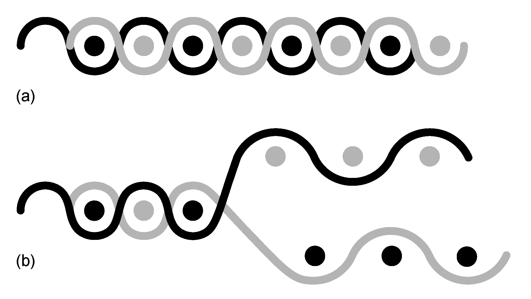
Jacquard weaving is a well-known technique where each warp thread can be raised independently of the other warp threads. This is in contrast to a plain weave, illustrated in
Figure 3a, for which the alternating warp threads are raised as a group during weaving.
The Jacquard technique allows the weaving of an almost unlimited variety of complex patterns, for example, for tablecloths or curtains. For the production of airbags, the ability to control each warp thread is used to create a double-layered fabric, as shown in
Figure 3b. This technique can thus be used to make an enclosed volume for an airbag. Additional layers can be added to create an internal structure such that flat pressurized structures can be realized [
42]. This is, for example, how curtain airbags for protecting car passengers from side impacts are manufactured. Jacquard weaving is a continuous process, and different products can be made with the same piece of fabric by just changing the steering program.
After weaving, the fabric is laminated with a foil to make it airtight and then cut to the right dimensions. For example, a prototype inflatable Tensairity spindle with geometry comparable to that found in [
43] was made with integral pockets for the compression elements. A limitation of Jacquard weaving is that each weft thread, no matter the layer, must have about the same length. This restricts the shape freedom of the pressurized structure to a certain degree but also gives the advantage that the pressurized structure is completely flat in its deflated state, allowing for a compact transport volume in the deflated state.
3. Structural Theory
Inflatable wings are commonly designed as lightweight woven structures that can maintain their aerodynamic shapes under load. As the potential energy of an inflated structure is proportional to the negative of the enclosed volume, the inflated shape can be determined as the geometry with the maximum internal volume [
44]. In the following, an analytic framework is derived that describes the shapes of pressurized structures of increasing complexity for use as inflatable wings. The theory is two-dimensional and applicable to the design of a wing’s cross-section. It assumes no stretch in the fabric, and thus membranes of infinite stiffness. An attachment of the wing to a fuselage, a tether, or a bridle-line system is not taken into account, and neither is a non-uniform external aerodynamic loading of the structures.
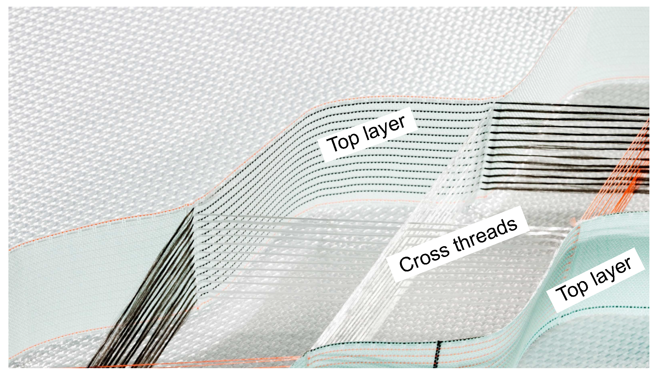
3.1. Mattress with a Single Cross-Thread Layer
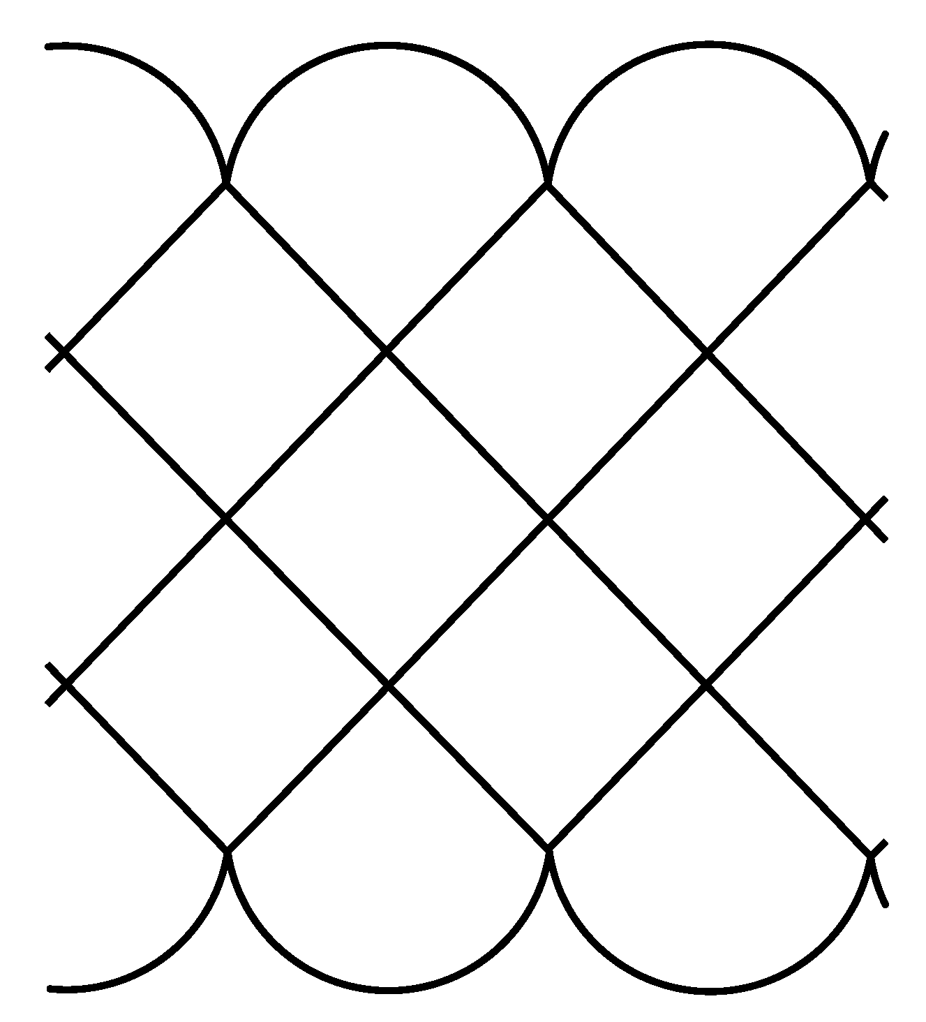
The most basic type of pressurized, woven multi-lobe structure has a cuboid shape, like an air mattress. A cross-section of such a structure with a single layer of cross threads is illustrated in
Figure 4.
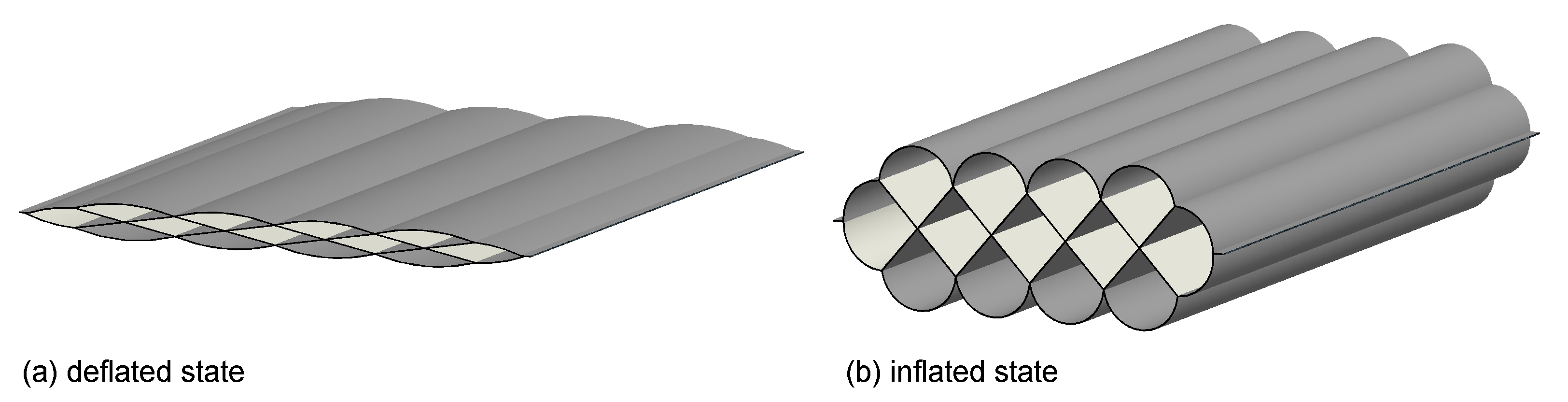
The deflated and inflated states are shown in
Figure 5.
A mattress segment is an internal volume between two opposing cylindrical top-layer sections. As the length
l of the mattress will not change upon inflation, the inflated shape is determined by the geometry with the maximum internal cross-sectional area.
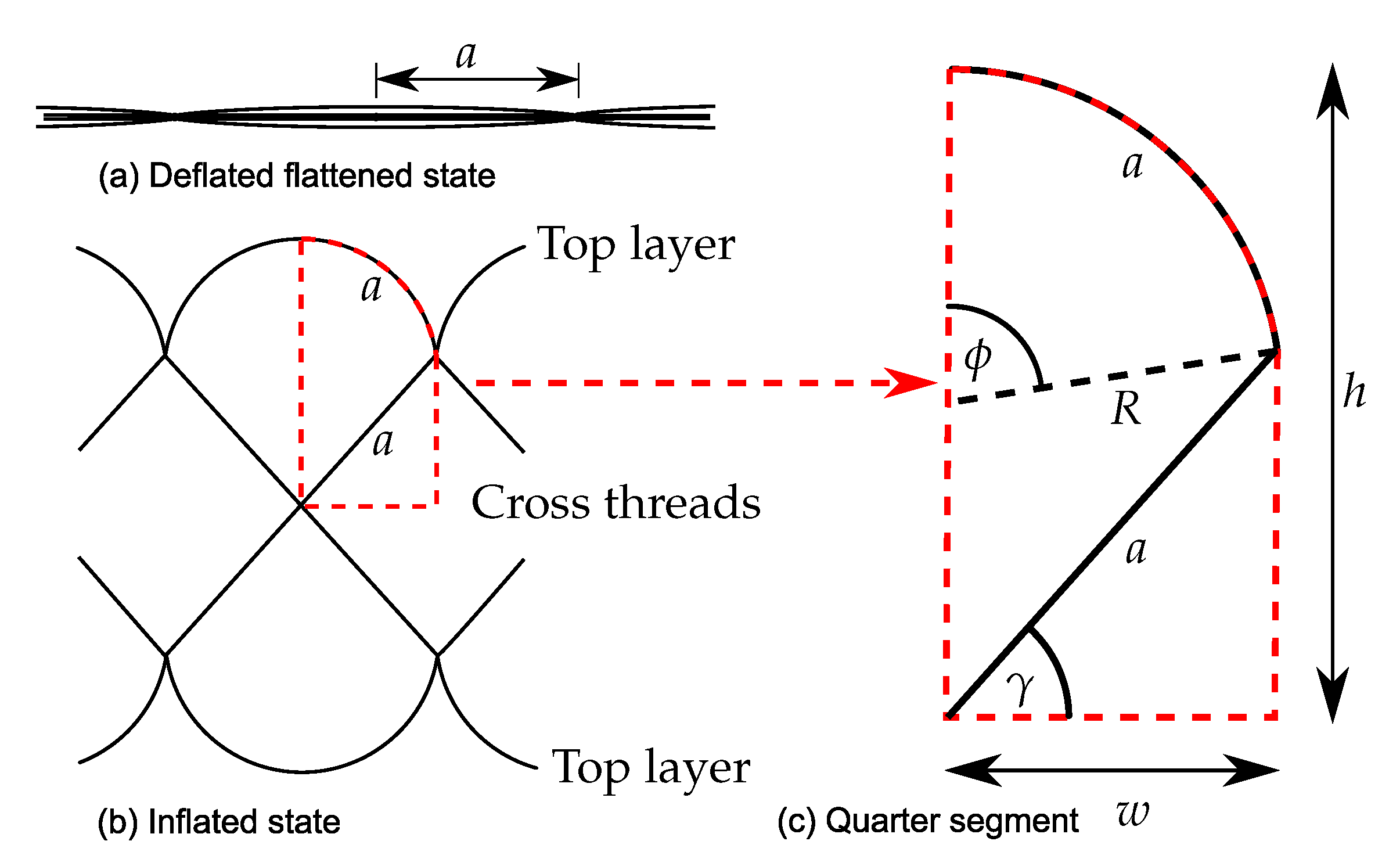
Figure 6a,b show the cross sections of the deflated and inflated structure.
Figure 6c shows an enlarged view of an inflated quarter segment of width
w and height
h.
The weaving technique results in top layers and cross threads of equal flat dimensions, which is why both have identical characteristic lengths
a. The geometric relations
can be combined to
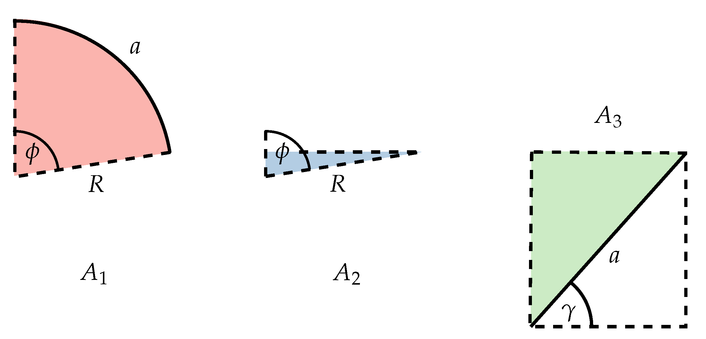
The total cross-sectional area
of the inflated quarter segment can be decomposed into the three partial areas illustrated in
Figure 7.
These partial areas are computed as
and then combined into
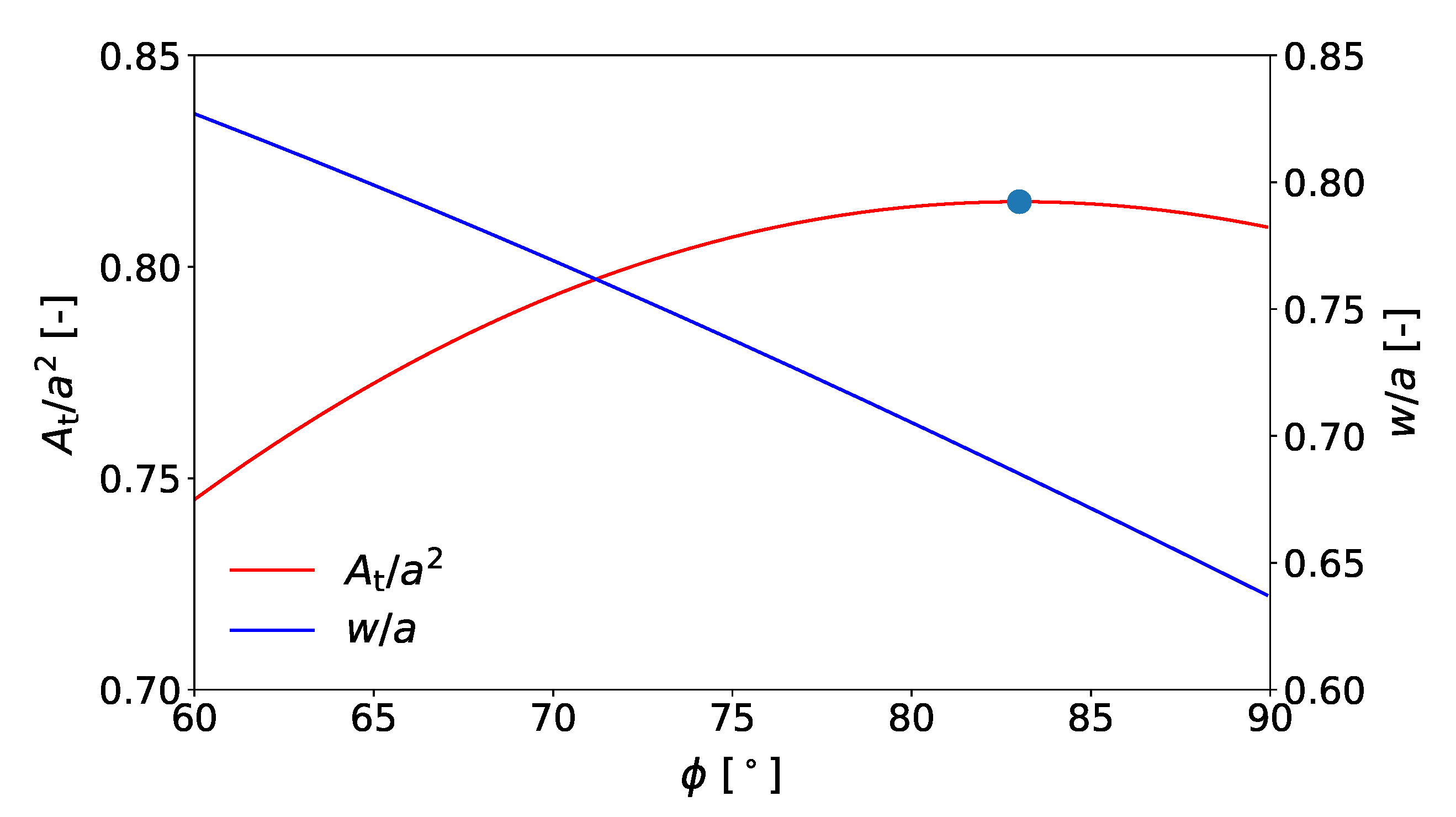
This relation between the angle
and the non-dimensional total cross-sectional area
is plotted in
Figure 8, together with the non-dimensional width of the quarter segment given by Equation (
3).
The maximum value of
can be determined numerically and is included in the figure as a red dot. The optimal geometry of the mattress’s cross-section corresponding to this solution is detailed further in
Table 1, listing the non-dimensional values of all parameters.
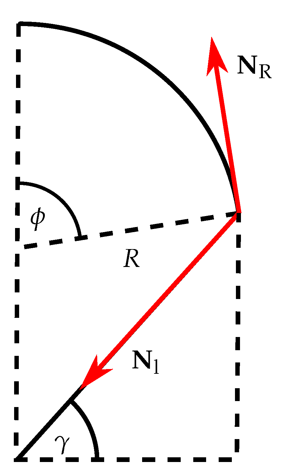
In a next step, the forces acting in the membrane structure are investigated. The point of interest is the connection of the top layer and the cross threads. The membrane forces acting at this point on one segment of the mattress are depicted in
Figure 9.
The vector
denotes the membrane force acting in the cross threads, and
is a hoop force acting in the top layer. Both are defined as forces per unit length. The magnitudes
and
can be calculated from the balance of vertical force components, as shown in the following, where
p denotes the overpressure in the structure, Equation (2) is used to eliminate
, and the value of
is taken from
Table 1Owing to the larger angle with the vertical, the membrane forces in the cross threads are higher than the hoop forces in the top layer of the structure. Thus, the forces in the cross threads dominate the design of the woven structure. This needs to be taken into account during the design and production of the mattress.
We performed measurements to verify the manufactured geometry with the designed geometry. These agreed well when the different elongations of the outer layers and the cross threads were taken into account. Elongations of the cross threads were about 5% and can be calculated with the forces given by Equations (
11) and (
12).
3.2. Mattress with Multiple Cross-Thread Layers
By adding additional layers of cross threads, the thickness of the mattress,
, can be increased while maintaining a constant width of the segment,
, as illustrated in
Figure 10. In this way, the structure can fill rectangular spaces more efficiently.
The formula for the cross-sectional area changes only slightly, by introducing the number
n of cross-thread layers as an additional parameter:
The numerical results of Equation (
13) are listed in
Table 2 for an various numbers of layers.
As expected, the area efficiency,
increases with
n, and the non-dimensional forces
in the cross threads decrease significantly. For reference, a circular area fitted into a rectangular area has an area efficiency of
.
Mattress designs with half layers (
), as shown in
Figure 11, are also feasible, but they are not as practical because the asymmetry of the tip regions leads to local distortions.
3.3. Structural Efficiency
Next to easy production and high area efficiency, high structural efficiency is important for lightweight pressurized structures. This metric is defined as the ratio of the pressurized volume
of the vessel t9 its mass
m [
31]:
For a pressurized structure of length
l with a constant cross-section, by neglecting the end caps, the structural efficiency can be formulated as
In the special case of a cylindrical structure, considering the hoop stresses
only, this leads to
where
u is the circumference and
t is the wall thickness. For a mattress with a single layer, one obtains with Equation (
7):
Evaluating this expression for the equilibrium value
(see
Table 2) leads to
which is identical to the structural efficiency of a pressurized cylindrical shell, given by Equation (
18). The same results for a mattress with multiple cross-thread layers:
It can be concluded that the structural efficiency of the woven pressurized mattress is the same as that of a cylindrical pressurized structure, but a woven pressure mattress has higher area efficiency, and therefore, will fill a cubical space, like under the floor of a car, more efficiently.
3.4. Tapered Mattress
The internal structure of the woven mattress can also be changed to make tapered or curved shapes. This is of particular importance for aerodynamic designs. By decreasing or increasing the length of the cross threads from one segment to the other, the woven mattress can have a tapered shape. Tapered mattresses with multiple cross-thread layers are also possible.
Figure 12 shows a single-layer tapered mattress.
In this specific case, Equations (
1)–(
3) have to be changed to
All other equations stay the same as for the flat woven mattress. The optimal angles,
and
, maximizing the area
for different values of
are given in
Table 3.
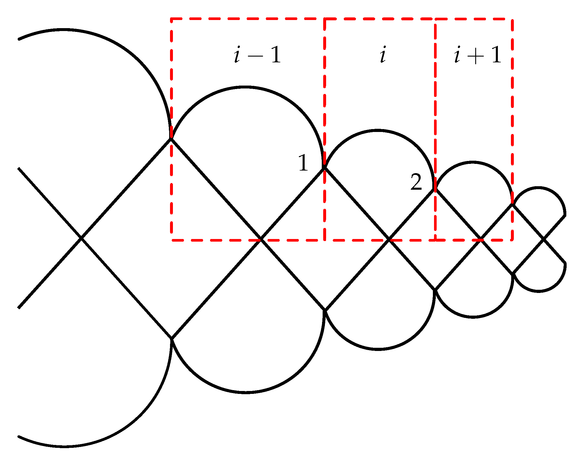
In a real structure, the shape is slightly different than the one determined by maximizing the area of a single segment. This is illustrated in
Figure 13.
Assuming all angles are equal for segments
,
i, and
(see
Table 3), the force in the cross thread of segment
i can be calculated by the force balance in either point 1 or point 2. This gives a slightly different result which grows with increases in angle
.
However, due to the flat optimum of the surface area, the deviation is small (at only 0.1%), and due to the flexible nature of the membrane, the structure will find a new equilibrium. Of course, if a certain precise outer shape is desired, the full structure can be optimized, providing the appropriate lengths of a. However, this optimization is shape-dependent and beyond the scope of this work.
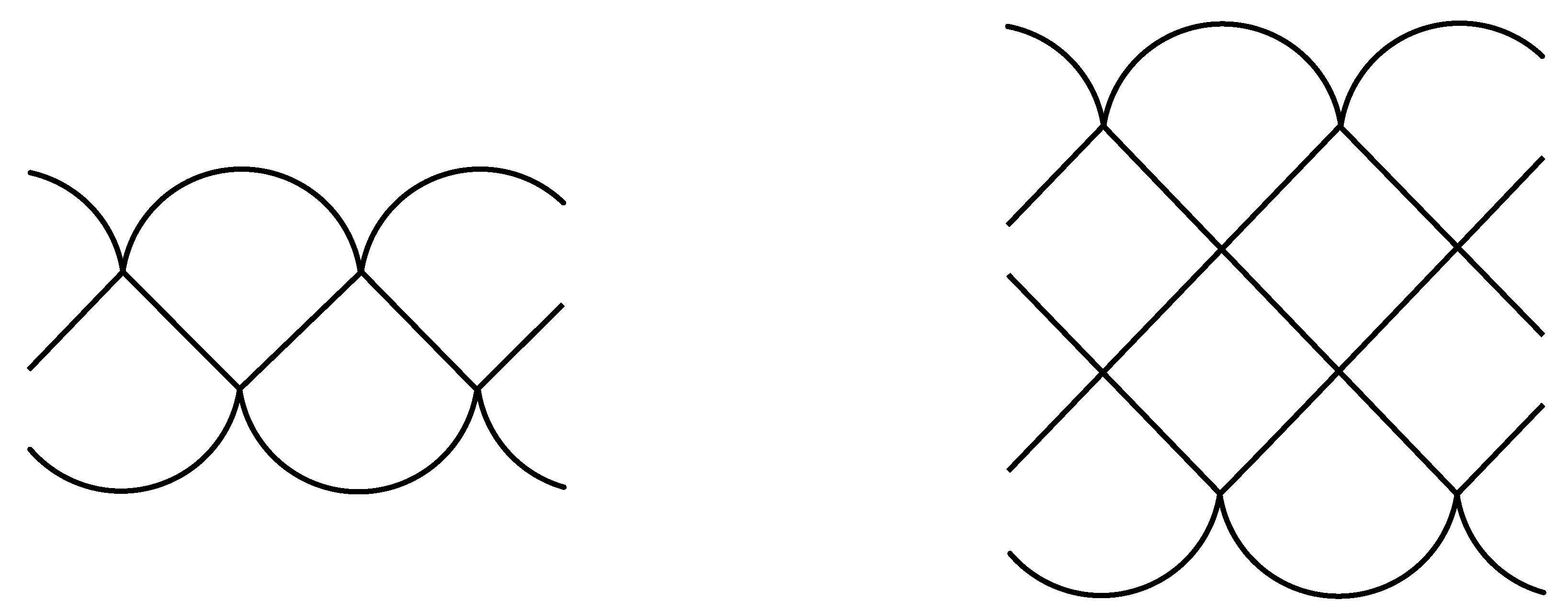
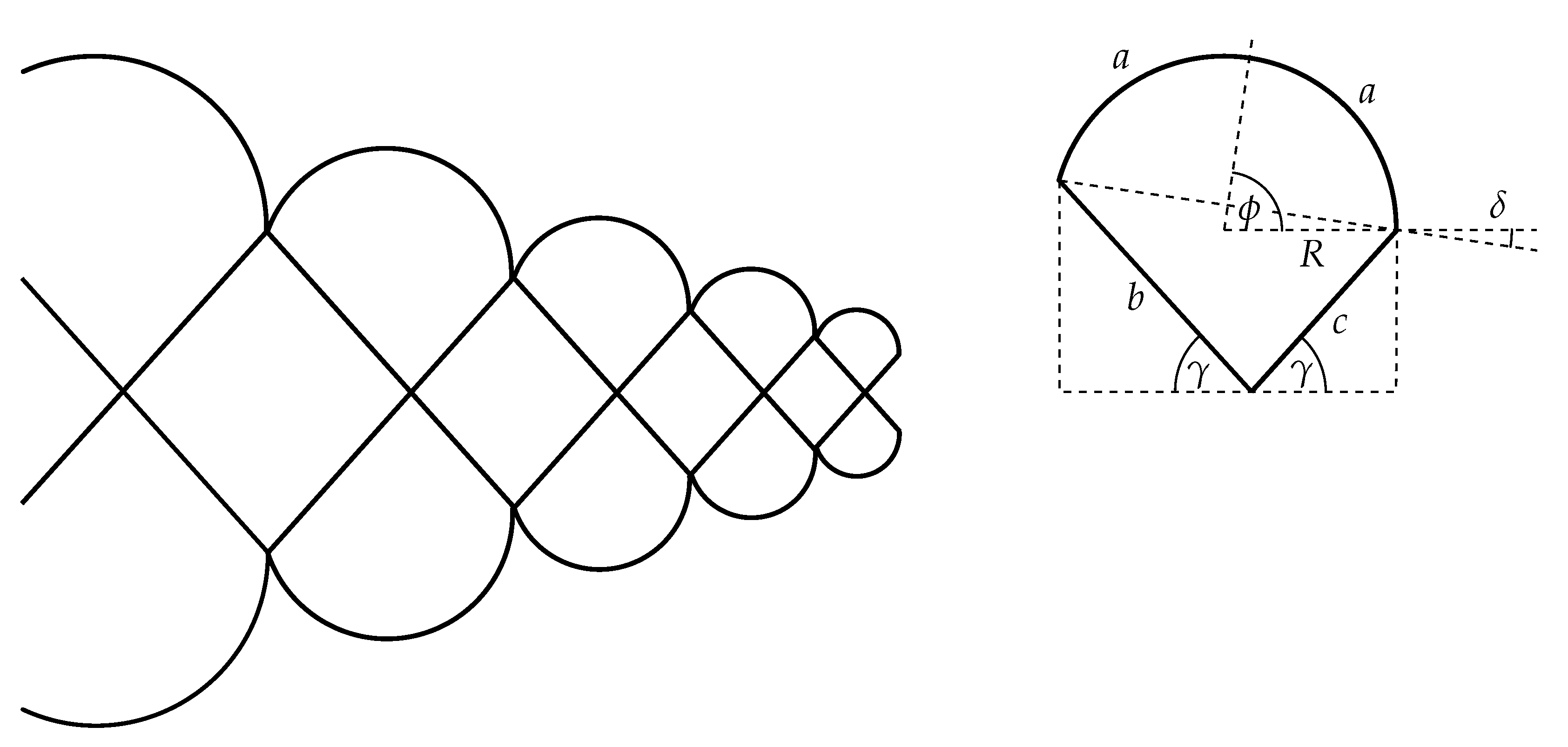
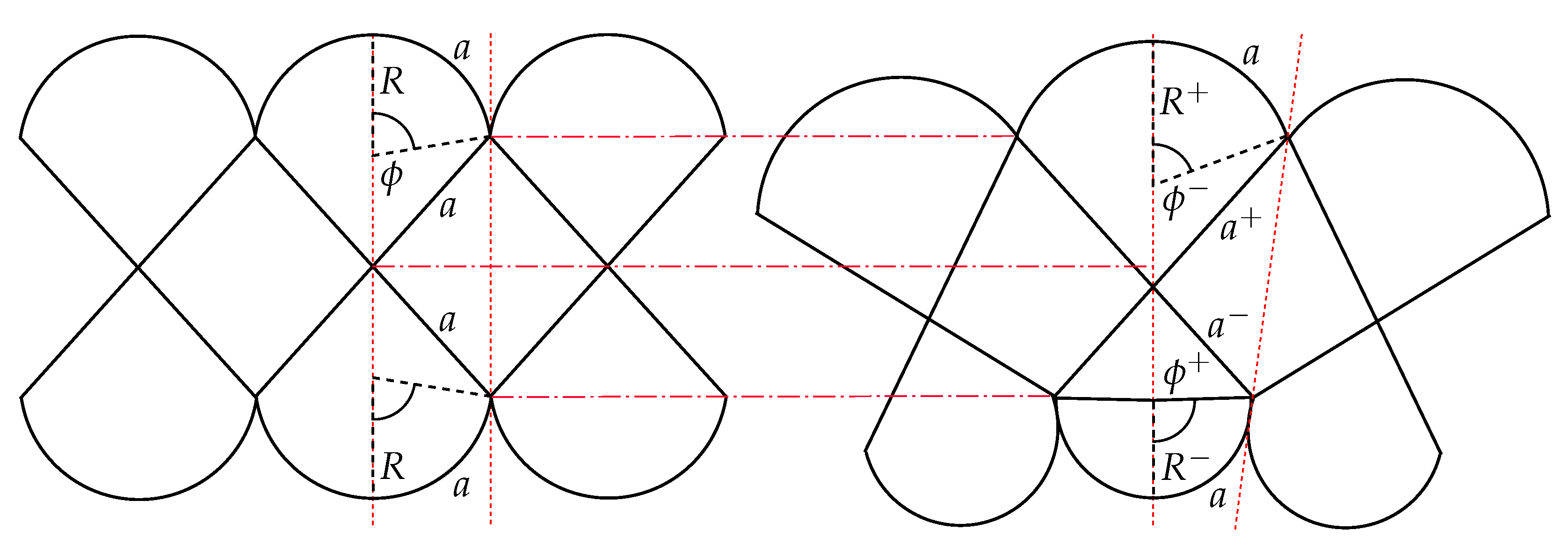
3.5. Curved Mattress
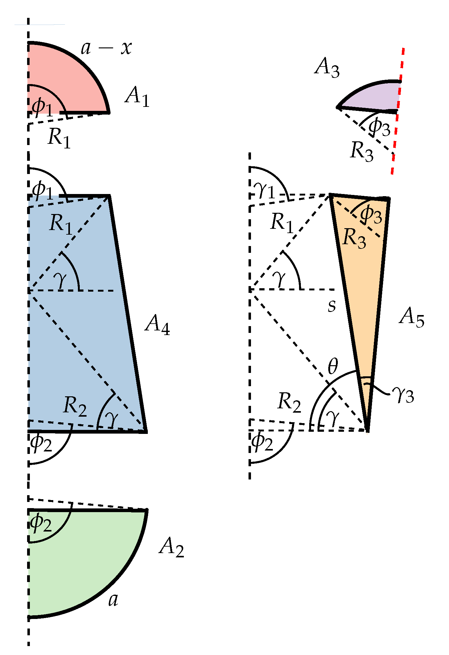
Curved structures can be created by adding extra circular segments on one side of the structure which is unsupported by cross threads. By varying the length ratio between the supported and unsupported circular segments, the local curvature can be controlled. The general layout and geometric relations are illustrated in
Figure 14.
The following geometric relations can be derived:
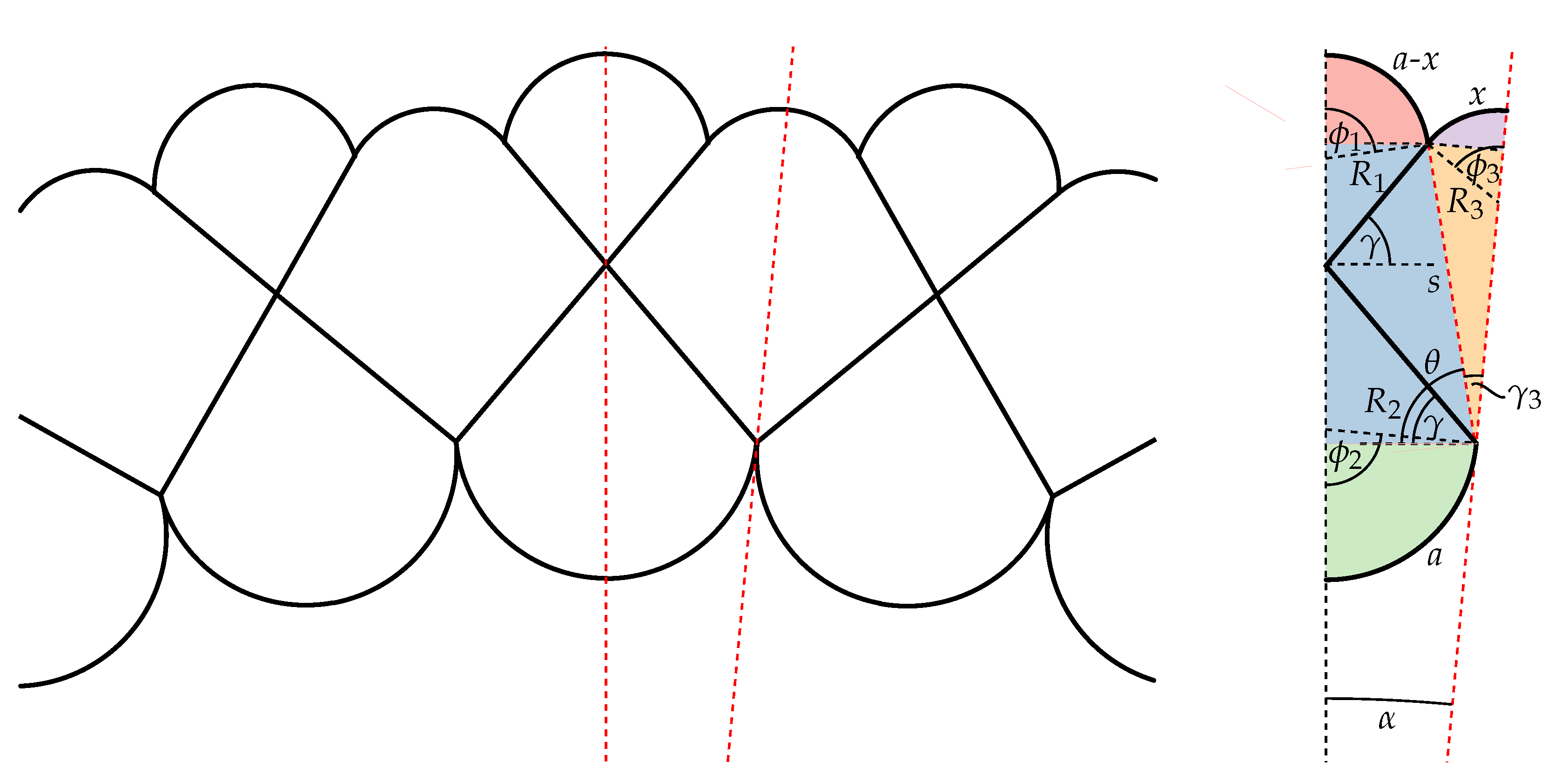
Determining the cross-sectional area is the same as in the previous examples; however, as shown in
Figure 15, it is more complex due to some extra formulas that are needed to describe the area contributed by the extra circular segment.
For a given value of x, the cross-sectional area is maximal for a specific combination of the angles , , and . The solution of this optimization problem shows that the absolute maximum of also satisfies the force balance.
The numerical results for different values of
x are given in
Table 4. These values of
x include the curvature of the woven mattress, which is defined as
For , the values are not useful anymore because the bottom circular segments () will touch each other. The curvature of the mattress can still be further increased, but a different set of equations needs to be used to take the circular segment’s contact into account.
4. Application Examples: Morphing Inflatable Wing
An interesting application for the presented technology is inflatable wings, which require high degrees of shape freedom and precision. Several prototypes of conformal woven pressurized structures were built, making optimal use of the cross threads and demonstrating the possibilities of the concept.
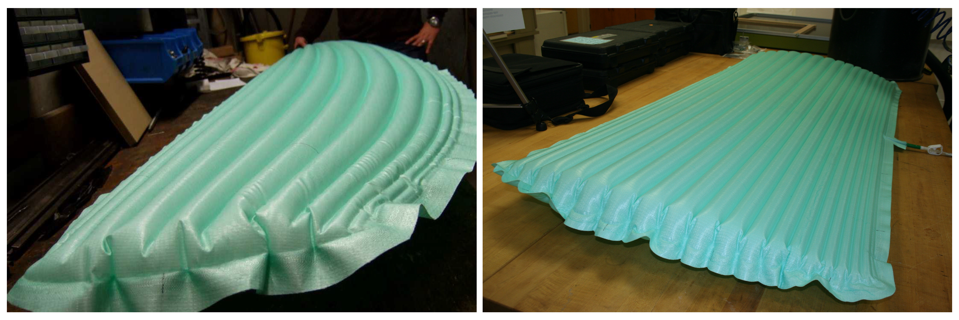
The first prototypes were elliptical wings to explore the range of wing shapes that could be realized. One of these early specimens is shown in
Figure 16 (left). Later prototypes had a rectangular planform for easier determination of the shape accuracy. One of these specimens is shown in
Figure 16 (right).
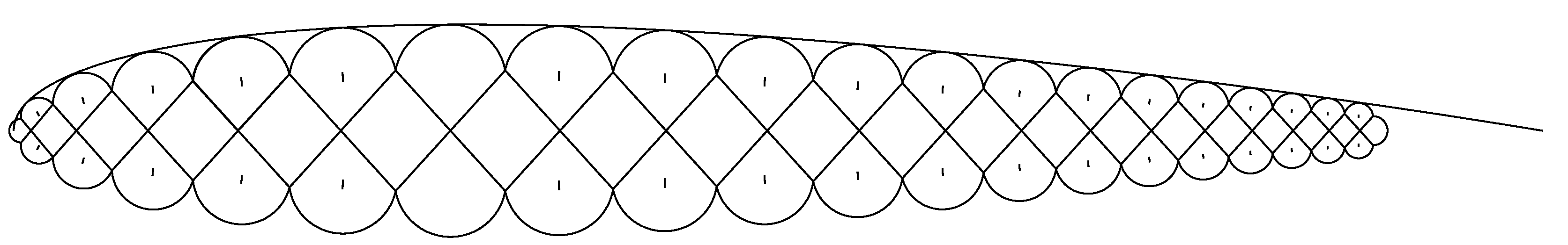
By accounting for stress and strain effects in the skin and cross threads, not presented in this paper, it was possible to very accurately build a wing with a NACA 0014 profile. An external skin can be added to flatten the circular segment surface of the woven mattress and improve its aerodynamic performance. A cross-section of the wing, showing the internal structure and the external skin on the upper side of the wing profile, is shown in
Figure 17.
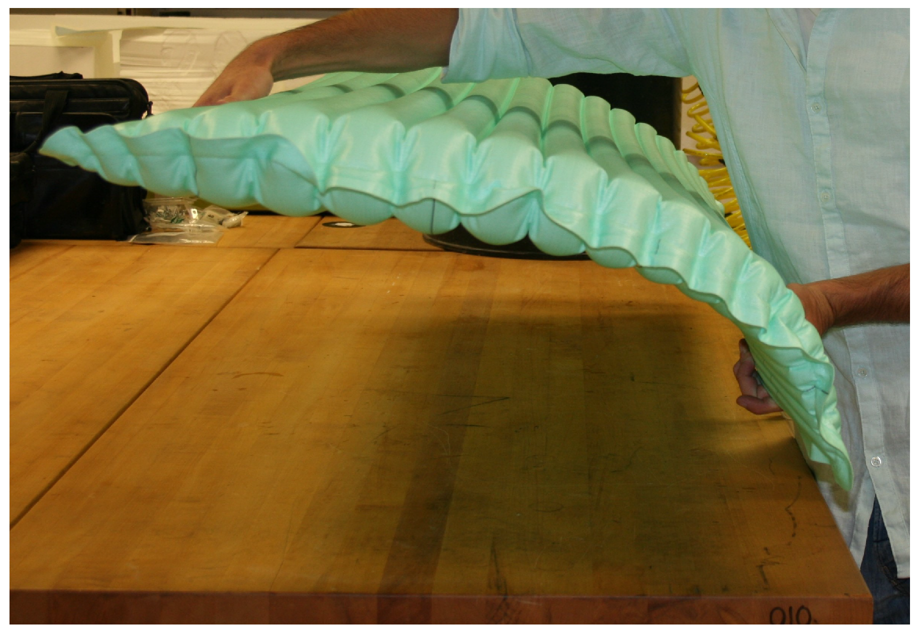
When the cross threads are not fixed at their point of intersection, the inflated wing is very flexible in a chordwise direction, making it suitable for morphing wings, e.g., for UAVs. This high flexibility is demonstrated in
Figure 18.
It can be explained by the functional dependence of a mattress segment’s cross-sectional area and width on the angle
, as shown in
Figure 8. Due to the flat maximum of the cross-sectional area, only little energy is required to bend the mattress in a chordwise direction by decreasing
and thus increasing
w for the upper layer and increasing
and decreasing
w for the lower layer. The geometric changes underlying this bending mechanism are illustrated in
Figure 19, indicating that the point of intersection of the cross threads needs to move to minimize the required energy. When this point is fixed, more bending energy is needed, which reduces the flexibility of the wing.
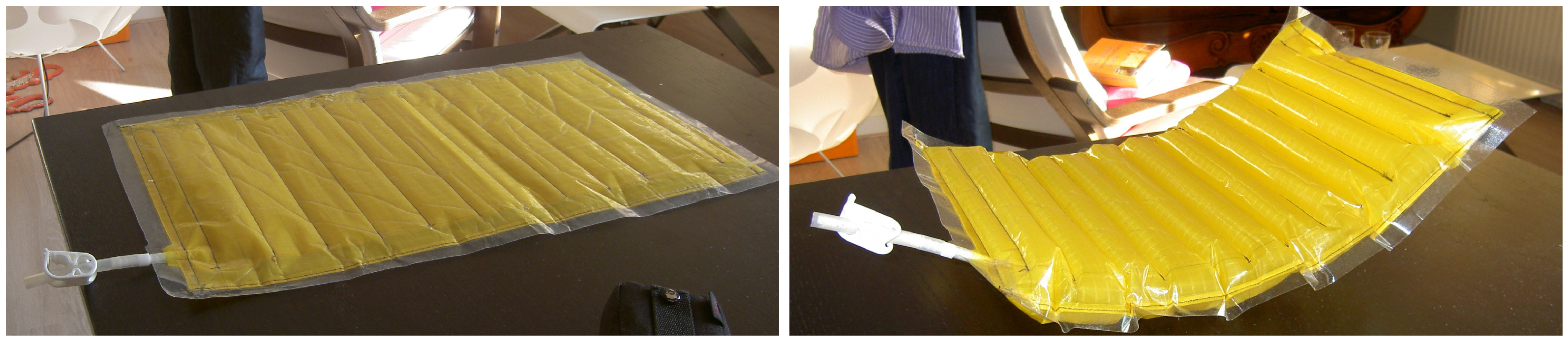
A permanent curvature can be obtained using the internal structure described in
Section 3.5.
Figure 20 shows how the flat initial shape starts to bend when inflated, as a consequence of the tensioning internal structure.
Other than the sample shown in
Figure 20, the woven prototypes were made using the standard Jacquard production techniques used for airbags, which highlights the potential of mass-producing woven pressure structures at the associated low cost. The current production line is focused on high-pressure airbags which are not airtight. Other applications of woven pressure structures might require long-term air tightness. The current prototypes showed some minor leakage where they were cut to size after the application of the airtight film. For long-term containment of pressurized gas or liquid, this needs to be improved.
Depending on the application, high-strength fibers might be used to increase the capacity of the woven structures to sustain high pressures. Another area of further study will be the reduction in stress concentrations where the circular segments and cross threads meet and at the edges of the structure.
The technique is thought to be only suitable for low-pressure vessels. With Jacquard weaving, thick shells cannot be made, as this would imply using thick threads. This limits permissible wall stress and thus the internal pressure that the structure can sustain. This effect can be reduced by adding more layers of cross threads and thus reducing the radius of the circular segments and the hull’s tension. The standard airbag Nylon weave used in the prototypes has a tensile strength of 2800 N/5 cm or 56 kN/m in warp direction. For a representative range of circular segment radius from 20 to 50 mm, this gives, according to Equation (12), an ultimate pressure of 2–0.8 MPa (20–8 bar), not including any safety factors and possible stress concentrations at the intersection of the cross threads and the circular segments. These pressure values are relatively low for any practical use as a pressure vessel, but by using high-performance fibers such as Kevlar or Vectran and thicker weaves, the performance can easily be increased without adding more cross threads.
Table 5 indicates the achievable failure pressures using Mil-T-87130 spec Kevlar webbing [
45], which is (among others) used for inflatable habitats. These values can be increased by adding more layers of fabric but can only be used to show the potential of the technique, as they do not include knockdowns due to local stresses at the crossing between the circular segments and cross tethers, end caps, and possible airtightness issues.
5. Other Application Options
The presented method of mass-produced woven pressure vessels opens up a wide range of applications for inflatables. The possibility for mass production and the experience in airbag production makes it very suitable for use in the automotive industry. Other than improving current airbags, it can be used for woven tanks for liquids or low-pressure hydrogen or natural gas. The technology can be used to make flat conformable tanks that can be located under the floor of a car. The flexible nature of the membrane will increase the crashworthiness of these tanks. Especially when using multiple cross threads, the radii and thus the forces in the membrane are very small, and thus, high internal pressures are possible with thin membranes.
Another application is their use as a lightweight replacement for foam in car seats. By adding extra chambers and control of the air pressure, they even can be made adaptable. This technique is also interesting for use in the airplane industry. Examples of pneumatic seat cushions for airplanes can already be found, but airbag technology will open up new markets and reduce costs. This idea can be extended to making lightweight (adaptable) mattresses for use in aircraft, but also for camping, as the woven pressurized structures are completely flat when deflated and thus have a high packing ratio.
6. Conclusions
The Jacquard weaving technique is particularly suitable for producing conformable pressure vessels. Despite certain limitations, a high degree of shape freedom can be achieved by changing the internal layout of the woven membrane structure. By adding extra cross threads, the stress in the membrane can be reduced, and the area efficiency can be improved. Woven pressure vessels have the same structural efficiency as cylindrical vessels but have the added advantage of being conformable. This, together with the possibility of mass production at a low cost, makes them attractive for applications in the automotive, aerospace, and leisure industries. The structural design patterns presented in this paper demonstrate the potential of the three-dimensional weaving technique for inflatable wings, which require high degrees of shape freedom and precision. Using one or more cross-thread layers together with the described tapered and curved mattress concepts, a wide variety of tailored wing shapes can be generated. These multi-segment membrane structures can be used as morphing wings with integrated actuators or with an external bridle-line system to provide additional support for applications with high aerodynamic loading of the wing. The approach allows for better wing shape control than conventional ram-air or leading-edge inflatable wing designs, but also comes with a weight penalty.


