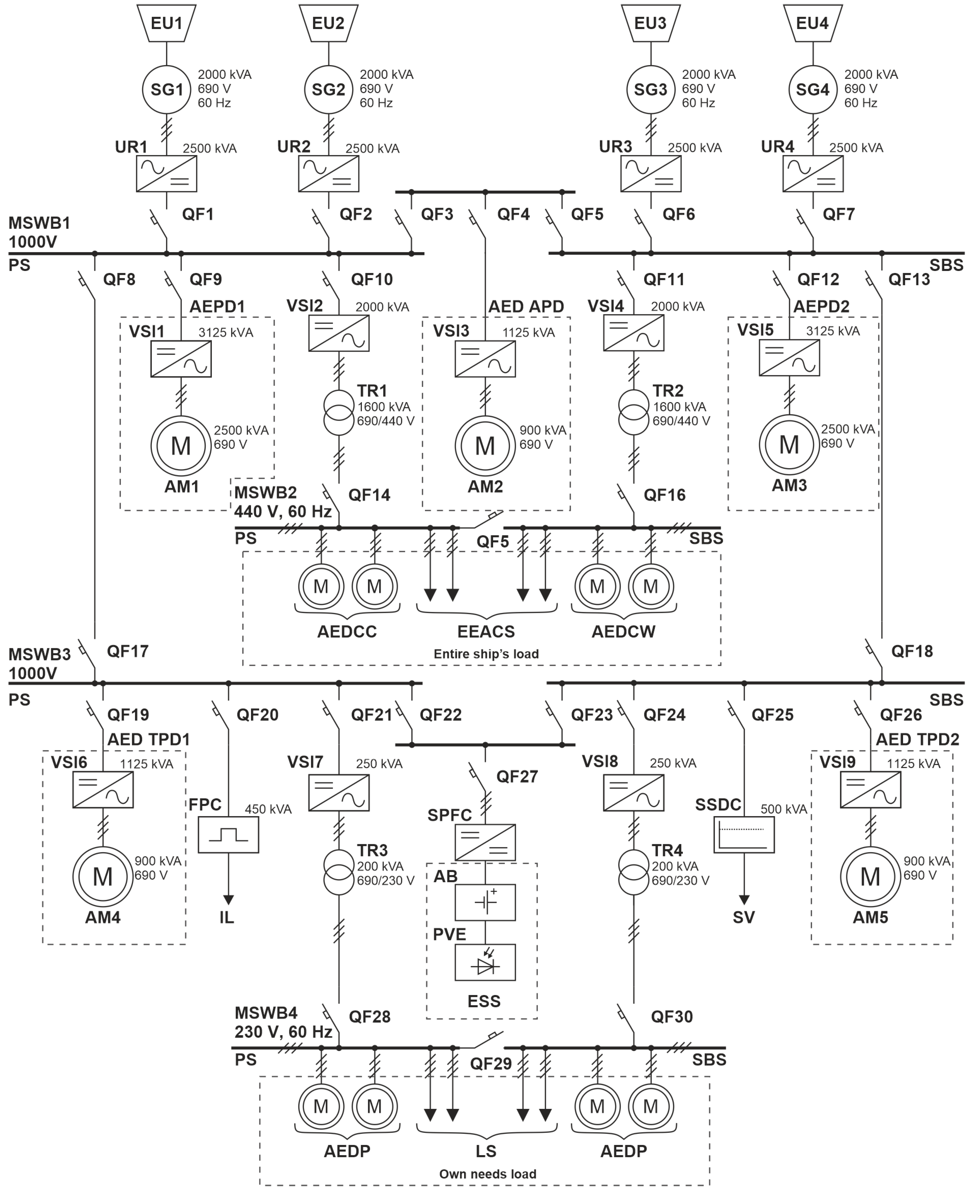
2.1. Structure and Parameters of the SEPS of the MPSV with EPC
In the presented SEPS, the leveling of strict requirements for phase and frequency synchronization of synchronous generators (SGs) allows for removing restrictions on the fixed speed of rotation of the DGU. The conditions for the most rational fuel consumption are achieved due to the regulation of the DGU depending on the system total load. Other advantages of such SEPSs include the relatively low weight and size indicators of electrical equipment, the level of power losses, as well as the simplified integration with energy storage systems (ESSs). [
22,
23,
24,
25]. Estimated fuel savings on ships with such SEPSs when operating primary diesel engines (DEs) at optimal speeds are approximately 20–27% [
26]. At the same time, ESSs allow for somewhat relieving the DGU when working in peak load modes and thus reducing mechanical and thermal stresses in the system.
The basis of the SEPS in
Figure 1 consists of DC bus systems MSWB1,3 with a nominal voltage of
V and AC MSWB2,4 with linear nominal voltages of
V and
V. The power supply in the ship’s power plant is four synchronous generators (SG1-4) with an installed full nominal power of
kVA. The linear nominal voltage of each generator is
V.
A group of PSCs for system purposes (PSC SP1)—uncontrolled rectifiers (UR) UR1-4 with the installed full nominal power of kVA—provides DC voltage to MSWB1,3 through switches QF1,2,6,7 and QF8,13,17,18. For the AC voltage feeding MSWB2 from MSWB1 through QF10,11 and QF14,16, voltage source inverters (VSIs) with pulse width modulation (PWM)—VSI2,4 ( kVA)—in groups with step-down transformers TR1,2 ( kVA, V) are used.
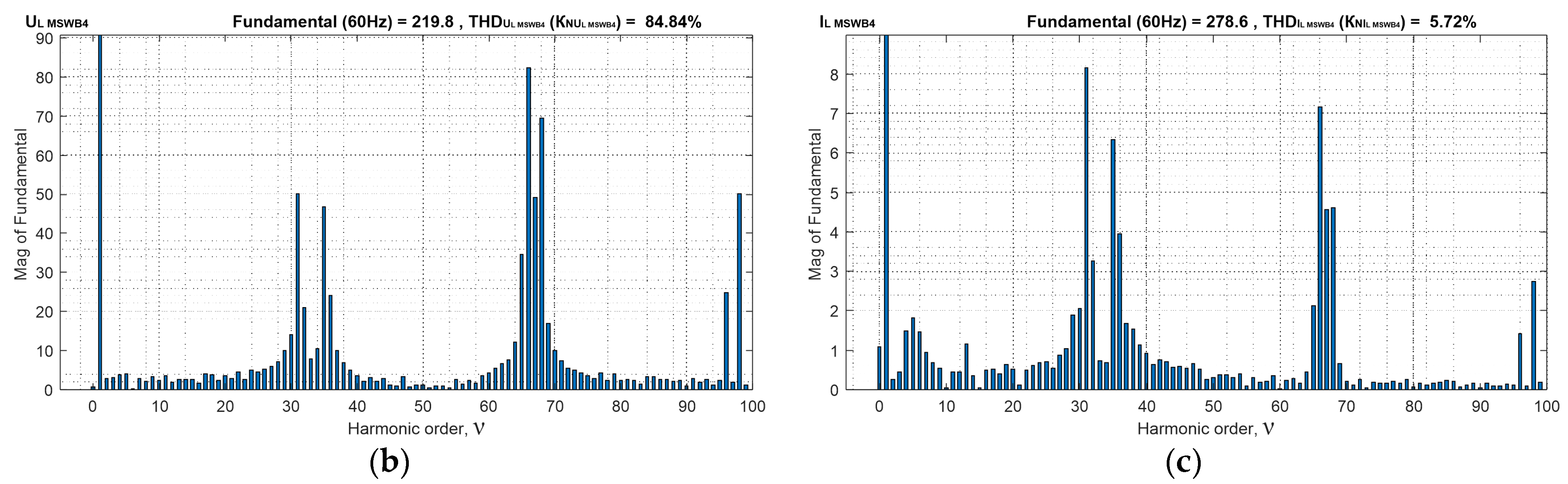
For the AC voltage feeding MSWB4 from MSWB3 through QF21,24 and QF28,30—VSI7,9 ( kVA)—in groups with step-down transformers TR3,4 ( kVA, V) are used. Converters VSI2,4,7,9 in a set with transformers TR1,2,3,4 belong to the second group of PSCs SP2. The main power loads on the MSWB1 in the SEPS are the main propulsive installation based on frequency-regulated asynchronous electric propulsion drives (AEPD1,2) according to the “VSI with PWM—asynchronous motor (AM)” scheme ( kVA, kVA) and the asynchronous electric drive (AED) with frequency control of the azimuth propulsion device (APD) according to a similar scheme with kVA and kVA.
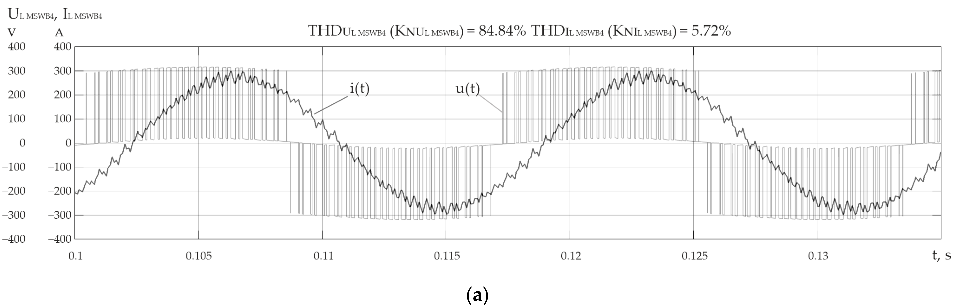
The AEDs of tunnel propulsion devices (TPD1,2) ( kVA, kVA) are connected to MSWB3, which are similar in terms of power and schematic implementation to the previous ones. In addition to the electric drives of the thrusters, frequency pulse converters (FPCs) kVA, stabilized direct current sources (SSDCs) kVA, and energy storage systems (ESSs) kVA with stabilized frequency pulse converters (SFPCs) are connected to MSWB3.
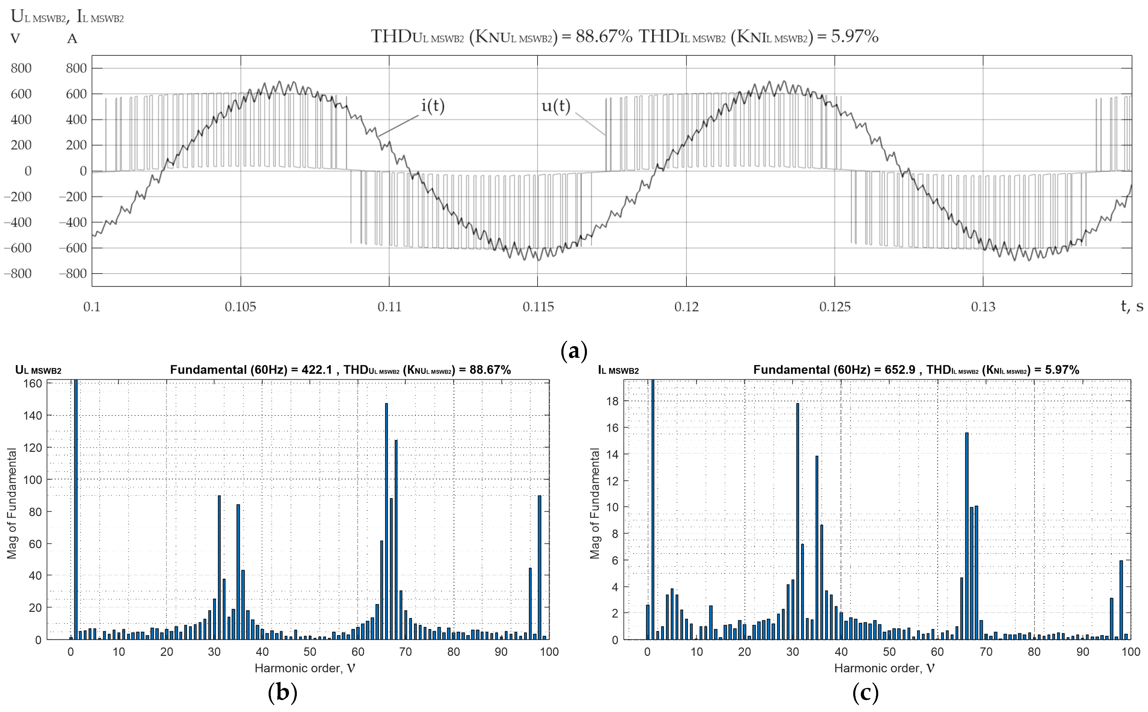
Ship-wide loads (with a total capacity of kVA)—AED of cargo cranes (AEDCC) and AED of cargo winches (AEDCW), and electrical equipment of air conditioning systems (EEACS)—are connected to MSWB2, and self-needs loads (with a total capacity of kVA)—AED of pumps and lighting systems (LS)—are connected to MSWB4.
The sectioning of MSWB1,3 and MSWB2,4 using switches QF3,5 and QF22,23, and QF5 and QF29, respectively, allows one to reserve the power of DGU1-4 in the case of changes in the level of loads on the buses of the corresponding boards. By using an adjustable SFPC in a complex with ESSs, based on accumulator batteries (ABs) and photovoltaic elements (PVEs), short-term stabilization of the constant voltage on the MSWB3.1 buses during transient modes of the SEPS is simultaneously achieved, as well as indirect regulation of the active/reactive power on the AC bus current of MSWB2,4 [
22]. According to the scheme (
Figure 1), it is possible to identify the most powerful consumers in the SEPS of the MPSV, which are listed in
Table 2 with their main operation modes.
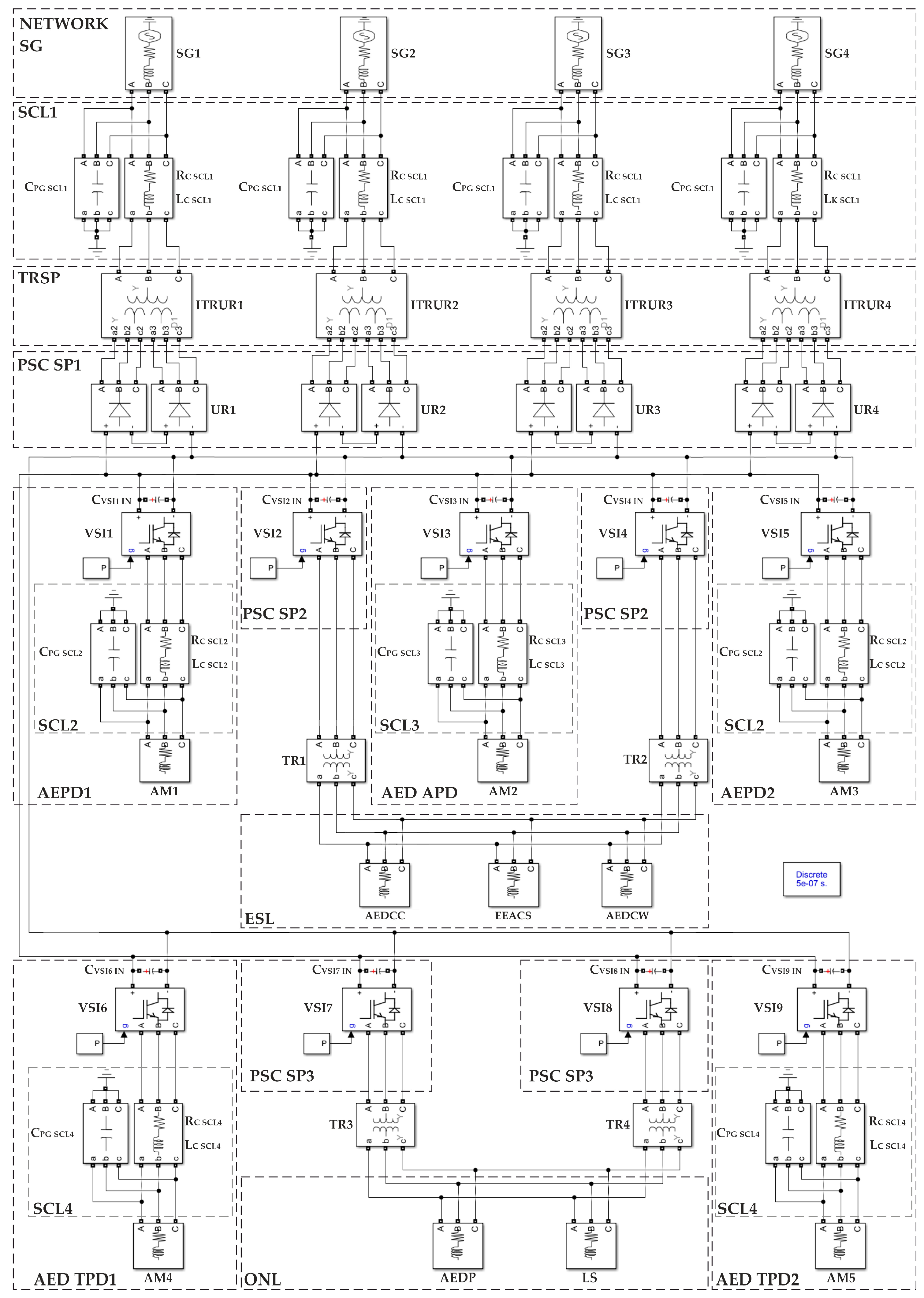
2.2. SEPS Model Structure of the MPSV with EPC and Methodology for Derivation of Its Parameters
For the analysis of EPQI in the electric power system of the MPSV, according to the diagram in
Figure 1, a MATLAB model is developed, which is shown in
Figure 2.
Emphasis in this work is focused on the study of the influence of the most powerful power semiconductor converters in the propulsion electric drives of ships with dynamic positioning on the electricity quality indicators, related to the non-sinusoidal shape of the voltage and current curves of the SEPS. Therefore, the insignificant effect of the converters, which are part of the radio communication and radio navigation complex and have several orders of magnitude less power, is neglected. The corresponding low-power SSDC and pulse converters are shown among consumers in the single-line scheme of the SEPS (
Figure 1), but in the MATLAB model (
Figure 2), they are not taken into account.
Based on the SEPS scheme (
Figure 1), the following parameters of a single SG for the model are chosen: full nominal power
kVA, nominal linear voltage
V, and output voltage frequency
Hz. As a basic version of the generator, the MARELLI Generator MJBM630-SC8 (SG clear-pole, 4 pairs of poles, 900 rpm) is taken [
27]. In
Figure 2, SGs are represented by identical “3-phase voltage source” blocks. According to their reference data, the power factor
is chosen, as well as super-transitional resistances along the longitudinal and transverse axes, respectively,
hp and
hp [
21,
28]. The nominal active and reactive powers of SG are:
The phase voltage of generators is
V. The inductive resistance, inductance, and active resistance of each SG are determined as follows, respectively [
21]:
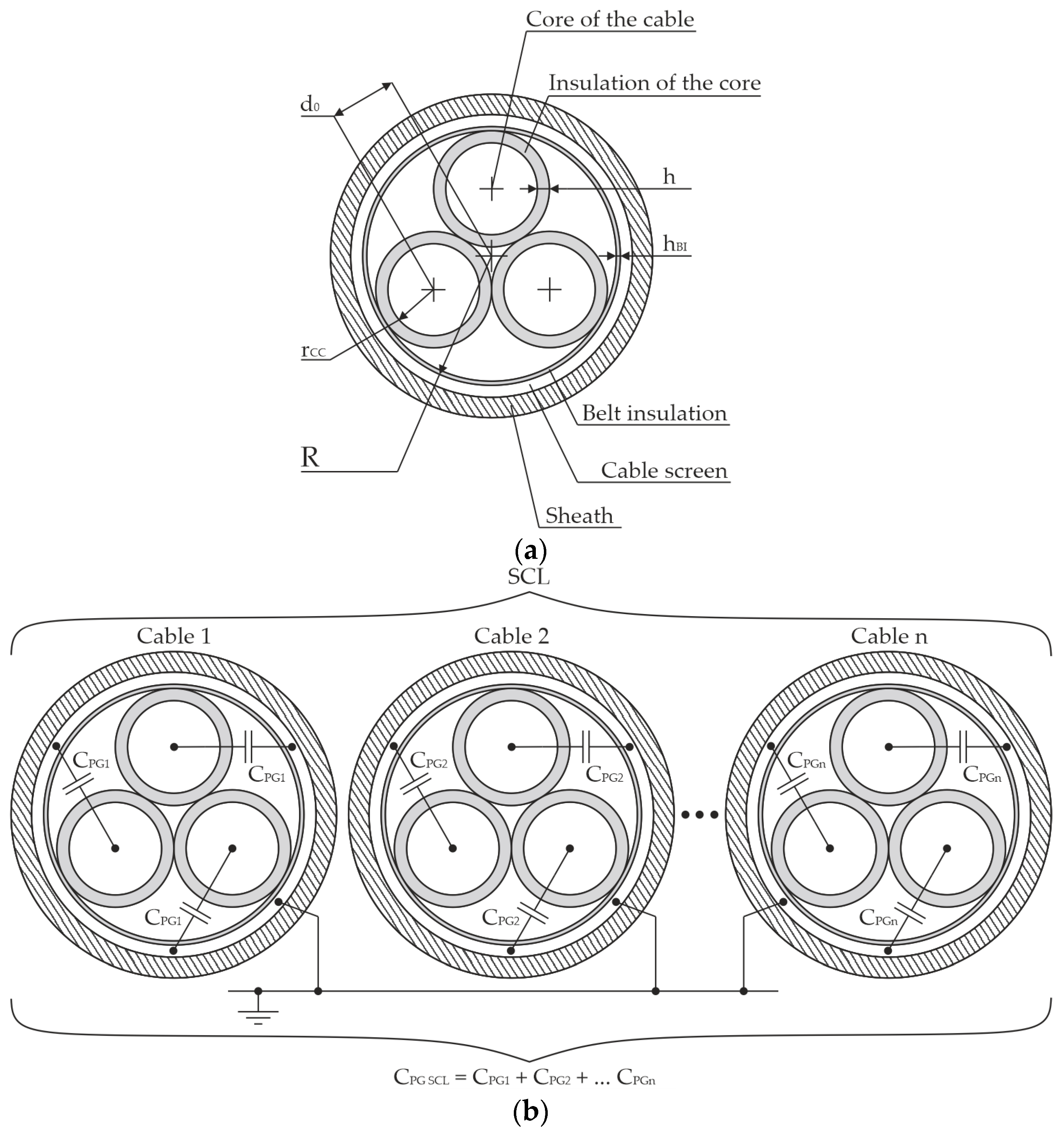
Sections of cable lines (SCL1) from the network of generators SG1-4 to PSC1-4 of system purposes in
Figure 2 are shown as “Three-phase series RLC branch” blocks. Based on the technical indicators of the MPSV (typical project), the length of the specified sections equal to 12 m is chosen [
1]. The linear current in SCL1 is determined by the ratio:
Accepting the efficiency coefficient of the cable efficiency
and taking into account that
[
21], from (1), we obtain
A. As a basic option, for SCL1, a 3-phase shielded cable LKSM-HF FLEX 0.6/1 kV 3 × 185 mm
2 [
29] is chosen with a nominal current of
A. Taking into account the calculated value
, it is assumed that each SG in the scheme (
Figure 2) is connected to the corresponding one by an input step-down transformer of an UR (URT) by 6 phase-parallel-connected sections of the mentioned type of 3-phase cable, each 12 m long. Taking into account [
28], we can write down the ratio for determining the parameters of SCL1 cables, which are included in the SEPS model (
Figure 2). The ratios for calculating the active, inductive resistance (Ohm) and the inductance of cables (H) in the composition of SCL1 have the following forms:
where
and
are active and inductive resistances of 1 m of cable, respectively, reduced to one phase, Ohm/m [
28,
29];
is the length of the section SG to URT, m;
is the number of parallel sections of the cable on section SG to URT;
is the generator voltage frequency, Hz.
According to the conditions of electrical installation and electrical safety [
30], the shield provided by the design of LKSM-HF FLEX 0.6/1 kV 3 × 185 mm
2 has a galvanic connection with the ship’s hull. The running capacity “phase to ground” (F/m) of such a cable is determined by the ratio [
30]:
where
—dielectric constant of insulation;
—radius of the inner surface of the screen, mm;
—distance between the longitudinal axis of the cable and the axis of the core, mm;
—core radius of the HF FLEX 0.6/1 kV cable 3 × 185 mm
2, mm;
where
—cable core insulation thickness, mm;
—belt insulation thickness, mm;
where
—cross-sectional area of the cable, mm
2.
Taking [
30] into account, for our conditions, the “phase-to-ground” capacitance of SCL1 (F) between SG and URT is determined by the ratio:
The model also takes into account sections of cable lines between power semiconductor converter (VSI) EPCs and asynchronous motors as part of the AGED1,2, AED APD, and AED TPD1,2, respectively: SCL2—75 m (VSI 1.5-AM1.3), SCL3—45 m (VSI 3-AM2), and SCL4—55 m (VSI 6,9-AM4,5). A typical design of a 3-phase power shielded cable is shown in
Figure 3a. Parasitic capacitances of the “phase-to-ground” section of the cable line are shown in
Figure 3b. Based on (1) the ratio for the linear current (A) in each section:
where
—nominal active powers of VSI 1,3,5,6, and 9, respectively;
;
.
Assuming
and according to the scheme (
Figure 1),
kVA,
kVA, and
V, from (10) to (12), we have
A,
A, and
A.
Taking into account the nominal values of the linear currents for switching VSIs and AMs on SCL2,9, phase-parallel-connected sections of the LKSM-HF FLEX 0.6/1 kV 3 × 185 mm
2 (
A) are chosen, and on SCL3 and SCL4—5 sections of the LKSM-HF FLEX 0.6/1 kV 3 × 95 mm
2 cable connected in phase-parallel are chosen (
A) [
29]. In the same way to determining the parameters of SCL1 cables, it is possible to obtain ratios for SCL2,3,4.
Based on (2)–(4), the active, inductive resistance and inductance of the cables in the composition of SCL2,3,4 are as follows:
where
and
—active and inductive resistances of 1 m of cable (according to the type selected for SCL), respectively, reduced to 1 phase, Ohm/m;
,
, and
and
,
, and
—lengths (m) and the number of parallel sections of cable in the corresponding areas, respectively;
—output frequency of the PSC EPC, Hz.
Based on (9), the “phase-to-ground” capacity of SCL2-4 is determined by the ratios:
where
and
is determined from (5) by taking into account
,
,
, and
for the cable LKSM-HF FLEX 0.6/1 kV 3 × 95 mm
2 in the respective areas.
In the MATLAB model (
Figure 2), dual-bridge 12-pulse Urs as part of the PSC SP1 group are implemented on the basis of the “Universal bridge (Diodes)” blocks with phase-shifting three-winding transformers URTs (
Figure 2) on the basis of the “Three-phase transformer (Three Windings)” blocks with the “Y-Y-Δ” windings connection.
Taking into account [
21,
31], the active, inductive resistance (Ohm) and inductance (H) of the URT for our case are determined as follows:
—For “Y” windings connection:
—For “Δ” windings connection:
—full rated power of the transformer, VA;
—linear nominal voltage of the transformer winding, V;
—transformer short-circuit voltage, hp.
VSIs with PWM as part of the PSC SP2,3 and EPC groups (AGED1,2, AED APD, AED TPD1,2) in the model scheme are implemented according to a 3-phase bridge scheme based on “Universal Bridge (IGBT/Diodes)” blocks with external control from the PWM signal generator—the “PWM Generator (2-level)” block. In VSI blocks with PWM, 2-level voltage modulation is used with frequency Hz.
The input capacitances (F) of VSIs with PWM1-9 are determined by the ratio of [
32]
where
—rectified voltage at the input of the VSI (at the output of the 12-pulse UR in the composition of PSC SP 1 [
33]), V;
—allowable voltage increase on the input capacitor VSI, V;
—time constant of the load cycle VSI, c (
—load phase inductance, H;
—active resistance of the load phase, Ohm) [
32].
The total resistance of the load phase (Ohm) is determined by the ratio:
The voltage (V) and current (A) in the VSI phase have the form:
where
—VSI modulation index;
—full power of VSI, VA.
The inductive resistance (Ohm) and phase inductance (H) of the VSI are:
Groups of step-down 3-phase transformers with “Y-Y” windings of system purposes TR1,2 and TR3,4 are implemented in the model based on the “Three-phase transformer (Two Windings)” blocks. By analogy with (17), the active, inductive resistance (Ohm) and inductance (H) of the transformer winding are determined by the ratios:
where
—transformer full nominal power, VA;
—transformer winding linear nominal voltage, V;
—transformer short-circuit voltage, hp.
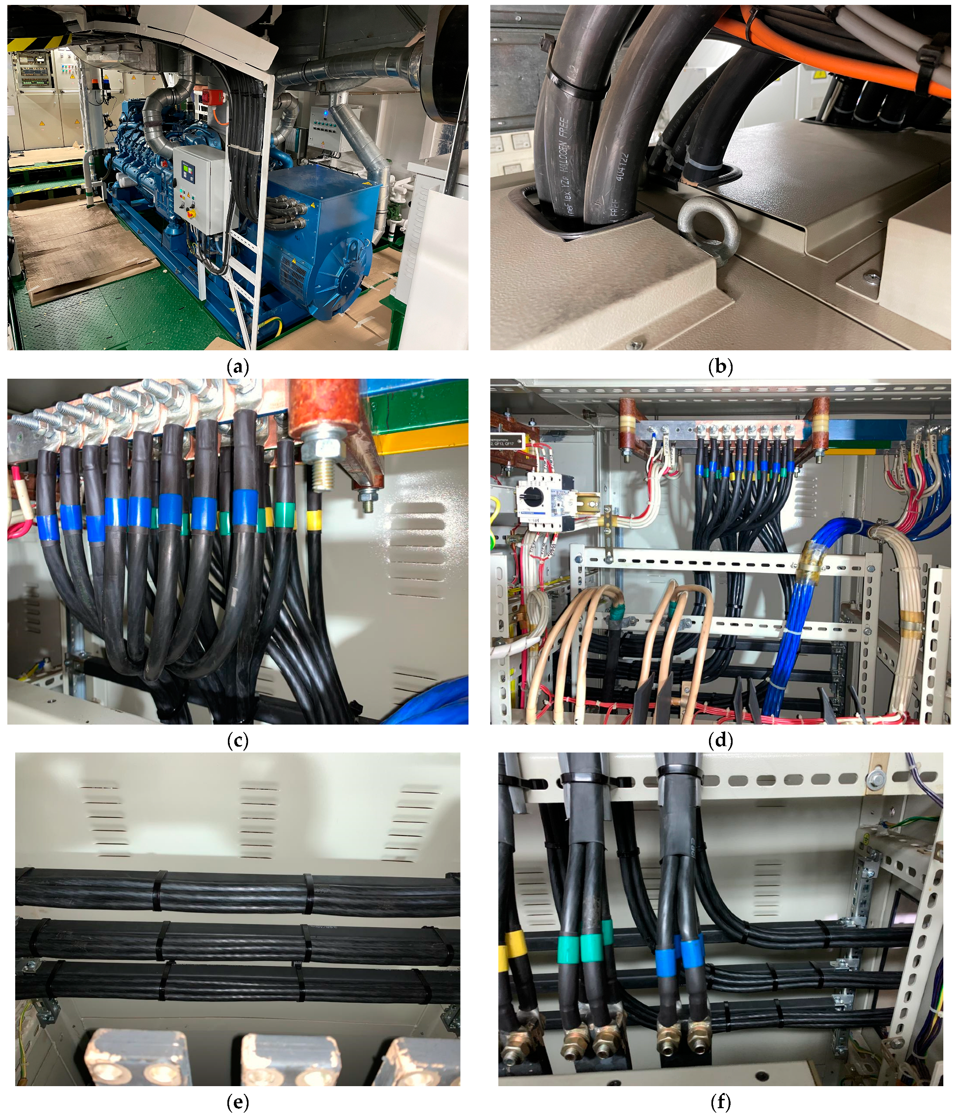
For better understanding,
Figure 4 shows external cable connections of Ukrainian-made power electrical equipment (designed and built in Mykolaiv) for vessels.


