Article

New Method to Coordinate Vibration Energy Regeneration and Dynamic Performance of In-Wheel Motor Electrical Vehicles

1
School of Mechanical and Power Engineering, Nanjing Tech University, Nanjing 211816, China
2
Jiangsu Key Lab of Design and Manufacture of Extreme Pressure Equipment, Nanjing 211816, China
3
School of Intelligent Transportation, Nanjing Vocational College of Information Technology, Nanjing 210023, China
*
Author to whom correspondence should be addressed.
Energies 2023, 16(7), 2968; https://doi.org/10.3390/en16072968
Submission received: 22 February 2023 / Revised: 16 March 2023 / Accepted: 21 March 2023 / Published: 24 March 2023
(This article belongs to the Section E: Electric Vehicles)

Abstract

:
A new method including suspension and wheel vibration energy regeneration is proposed in this study to coordinate the contradiction between vibration energy regeneration and dynamic performance of in-wheel motor electric vehicles (IWM-EVs). The influence mechanism of unsprung mass on the dynamic characteristics of IWM-EVs is investigated from the perspective of energy flow, and potential of energy regeneration of IWM-EVs is explored on this basis. A parameter sensitivity analysis of the proposed new method is conducted, and the optimal parameters are determined for a comparative simulation analysis among focus-driven electric vehicles, IWM-EVs, and IWM-EVs with linear electromagnetic dynamic vibration absorber (LEM-DVA). Results show that the proposed new method effectively improves the dynamic performance and achieves coordination between energy regeneration and dynamic performance despite its reduction of the vibration energy regeneration potential of IWM-EVs. A new structure, which integrates a linear electromagnetic damper (LEMD) and a LEM-DVA, is then proposed to implement the coordination method. The equivalent prototype and control system are designed for a hardware-in-the-loop test. The test results show good agreement with that of simulation despite some errors. This finding proves the effectiveness of the new structure in coordinating the vibration energy regeneration and dynamic performance of IWM-EVs.

1. Introduction

The electric vehicle (EV) is the main development direction of the automobile industry at present and in the future because of its energy conservation and environmental protection. As a special structure of EVs, the in-wheel motor electric vehicle (IWM-EV) omits transmission components, such as transmission, universal joint, and differential and half-axle, which reduces the vehicle quality, simplifies the vehicle structure, and improves the space utilization and transmission efficiency [1]. Moreover, the IWM-EV can realize complex motion and dynamics control through wire control technology. Owing to its unique technical advantages, the IWM-EV has gained unprecedented attention and development and has become a research hotspot [1,2,3]. However, many new problems introduced by the IWM-EV cannot be ignored. Particularly, the negative effect of vertical vibration caused by the increase in unsprung mass (installing the motor in the wheel can increase the unsprung mass), which will lead to an increase in dynamic tire load and poor road holding [4,5].
Many scholars have conducted useful explorations to solve the negative effect problem of vertical vibration caused by the increase in unsprung mass, and the methods can be summarized into three categories. The first is the lightweight design. The principle is to optimize the structure of the IWM to minimize its quality on the premise of ensuring the dynamic performance of vehicles. However, this method is limited by material strength, stiffness, and energy storage. The second is active suspension control. Shao proposed a multi-objective robust H reliable fuzzy control for active suspension systems of IWM-EV with dynamic damping [6]. Wang designed a finite-frequency state feedback H controller for the active suspension of IWM-EV, which improves ride comfort and road holding [7]. Zheng investigated the coupling mechanism of permanent magnet synchronous motor and proposed a multi-objective optimization method for the active suspension system to solve the negative coupling effects [8]. However, the active suspension yields a bulky structure and consumes a considerable amount of energy, which will affect the cruising range of IWM-EV. The third is the dynamic vibration absorber (DVA) design to transfer the IWM quality [9]. Luo proposed a novel electric wheel topology scheme with a built-in mounting system [10]. In this scheme, the IWM as a whole is elastically isolated from the unsprung mass via elastic element, and the IWM is transformed into the mass that is parallel to the sprung mass. Tian proposed structural schemes of the in-wheel powertrain system combining DVA. In this scheme, the in-wheel drive motor is suspended as a mass block; therefore, a DVA is mounted on the unsprung mass to absorb the vibration [11]. Although this method can effectively improve the negative impact of the increase in unsprung mass, it has some shortcomings, such as complex structure, poor sealing, and low reliability of moment transfer structure. In addition, the vibration energy, which can be regenerated, is wasted.
Overall, the current studies focus on suppressing the vertical vibration of IWM-EV. Therefore, the vertical vibration of IWM-EV is regarded as a negative factor because it will affect the dynamic performance of IWM-EV. However, the vertical vibration cannot be eliminated by any means. This vibration continuously exists in the process of IWM-EV driving. Thus, if the vertical vibration is considered from another angle, it can have a positive side [12]. The energy generated by vertical vibration can be converted into other energy (e.g., electrical energy) for reuse. Múčka [13] systematically evaluated the potential of vibration energy regeneration based on a real road database. The results show that for asphalt, concrete, and rigid pavement, the average dissipated power range of the four dampers of the whole vehicle model running at 60 km/h is 23.6 W to 25.9 W. The increase in the unsprung mass of IWM-EV intensifies the wheel vibration. Therefore, additional mechanical energy can be regenerated compared with conventional EVs. However, only a few studies focus on this aspect.
The common method for vertical vibration energy regeneration is to replace the hydraulic damper in the suspension system with a motor (linear/rotary motor). Thus, the mechanical energy generated by the relative motion of the vehicle body and wheel can be converted into electrical energy, which is dissipated as heat for the hydraulic damper. Guo [14,15] explained the principle of suspension energy conversion and proved the feasibility of the work of dissipated energy recovery. Shi [16] studied the influence of suspension energy recovery on the fuel economy of hybrid EVs. Zuo [17,18] analyzed the sensitive factors of vibration energy regeneration and designed an electromagnetic damper, which integrates a gear, a rack, and a motor to perform tests. The average vibration energy produced by the damper is 100–400 W when a medium-sized passenger car runs on a B- or C-grade road at 25 m/s. Abdelkareem [19] analyzed the main factors affecting energy regeneration and evaluated the recoverable energy on different road surfaces.
The aforementioned research demonstrates the feasibility of suspension energy recovery. However, only a few studies focused on the vibration energy regeneration of IWM-EV, mainly because the suspension system is passive or semi-active during vibration energy regeneration. Semi-active control can improve the dynamic performance to some extent but fails to coordinate ride comfort and road holding effectively [20,21]. Thus, the dynamic performance will be deteriorated due to the increased unsprung mass. In other words, vibration energy regeneration and dynamic performance improvement are always contradictory for IWM-EV, and a single vibration isolation system cannot effectively coordinate energy regeneration and dynamic performance. A new method for the vibration energy regeneration of IWM-EV, specifically, a linear electromagnetic damper (LEMD), is introduced in this study to regenerate the mechanical energy between the vehicle body and wheel. Moreover, linear electromagnetic DVA (LEM-DVA) acts as an “absorber” of the mechanical energy of the wheel. Thus, the vertical vibration can be effectively suppressed while recovering vibration energy.
The main contributions and innovations of this paper are as follows: (1) The influence mechanism of unsprung mass on dynamic characteristics of IWM-EV is investigated from the perspective of energy flow, and the energy regeneration potential of IWM-EV is explored on this basis. (2) A new method including suspension and wheel vibration energy regeneration is proposed to coordinate the contradiction between vibration energy regeneration and dynamic performance of IWM-EV. (3) A new structure, which integrates an LEMD and an LEM-DVA, is proposed to implement the coordination method.
This paper is organized as follows. Section 2 analyzes the influence mechanism of unsprung mass on energy flow and dynamic characteristics. Section 3 proposes a new method for the coordination of energy regeneration and dynamic characteristics. Section 4 designs the prototype to implement the coordination method and conducts a hardware-in-the-loop test. Finally, Section 5 provides a general conclusion.

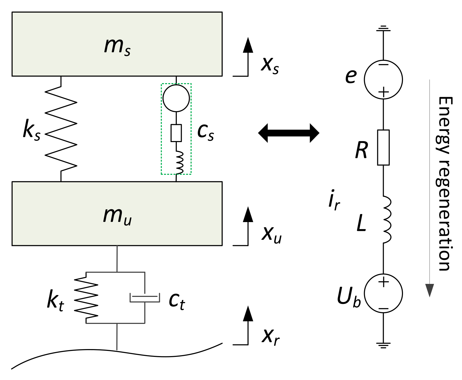
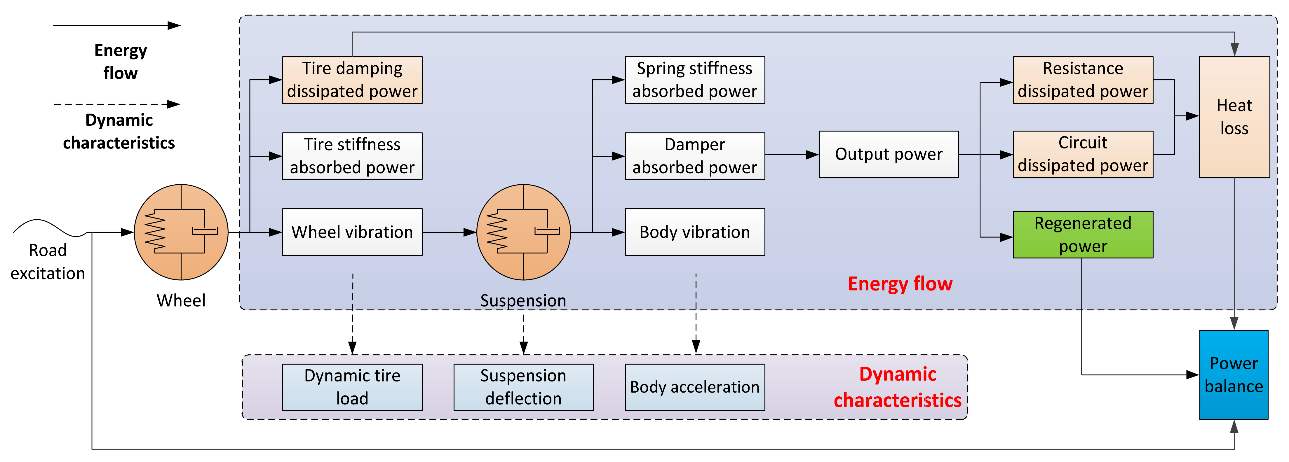
2. Influence Mechanism of Unsprung Mass on Energy Flow and Dynamic Characteristics

The increase in unsprung mass deteriorates the dynamic performance of vehicles. However, only a few research results explain the influence mechanism. Therefore, the influence mechanism of unsprung mass on dynamic characteristics is investigated from the perspective of energy flow, and the energy regeneration potential of IWM-EV is also explored.
As shown in Figure 1, one-quarter suspension with a linear electromagnetic damper (LEMD) of IWM-EV is taken as a research object, and a focus-driven EV is taken for comparison. The dynamic equation of a one-quarter suspension system can be expressed as:
m s x ¨ s = k s x s x u c s x ˙ s x ˙ u m u x ¨ u = k s x s x u + c s x ˙ s x ˙ u k t x u x r c t x ˙ u x ˙ r
where cs is the equivalent damping of LEMD during energy regeneration; xs and xu are the vertical displacement of ms and mu, respectively; xr is the motion excitation.
The stochastic road is employed as motion excitation, which can be represented as [22]:
x ˙ r = 2 π f 0 x ˙ r + 2 π n 0 G q ( n 0 ) v w
where f0 is the cut-off frequency, Gq(n0) is the road roughness coefficient, w is the Gaussian white noise with zero mean value, n0 is the space frequency that is equal to 0.1 m−1, and v is the vehicle velocity. The system parameters in Equations (1) and (2) are shown in Table 1.
Figure 2 shows the energy flow of a one-quarter suspension system under road excitation. The road roughness and vehicle velocity form the input power to the vibration isolation system. The input power flows into the wheel when absorbed by tire stiffness and dissipated by tire damping, which causes wheel vibration. The power is then absorbed by the suspension system (spring and LEMD) and flows into the vehicle body, which causes body vibration. Notably, the power absorbed by LEMD will be regenerated to electric power after its dissipation by internal resistance and regeneration circuit. The law of energy conservation states that the power flow into the vibration isolation system is always equal to the sum of dissipated thermal and regenerated electric power. Specifically, the wheel and body will continue to vibrate due to the continued existence of road excitation, and the power generated by the wheel and body vibration, despite the disappearance of road excitation, will be converted into heat loss and electric power until the vibration stops.
The root mean square (RMS) of power is taken as an evaluation index of energy to elaborate the influence mechanism of unsprung mass on energy flow and dynamic characteristics, and the RMS of body acceleration, dynamic tire load, and suspension deflection are taken for the evaluation of dynamic characteristics, which include ride comfort, road holding, and suspension working space.
According to Equations (1) and (2), the power absorbed by a tire can be expressed as [23]
R M S p t = 1 T 0 T k t x u x r + c t x ˙ u x ˙ r x ˙ u x ˙ r 2 d t
where the power dissipated by tire damping is
R M S p t d = 1 T 0 T c t x ˙ u x ˙ r 2 2 d t
and the power flow into the wheel is
R M S p t w = 1 T 0 T m u x ¨ u x ˙ u 2 d t
Similarly, the power absorbed by a suspension can be represented as
R M S p s = 1 T 0 T k s x s x u + c s x ˙ s x ˙ u x ˙ u x ˙ r 2 d t
where the power absorbed by LEMD (or the suspension vibration energy regeneration potential) is
R M S p s d = 1 T 0 T c s x ˙ s x ˙ u 2 2 d t
and the power flow into the body is
R M S p t w = 1 T 0 T m s x ¨ s x ˙ s 2 d t
In addition, the RMS of body acceleration, dynamic tire load, and suspension deflection is, respectively, shown in Equations (9)–(11) [20].
R M S a c c = 1 T 0 T x ¨ s 2 d t
R M S d t l = 1 T 0 T k t x u x r + c t x ˙ u x ˙ r 2 d t
R M S s d = 1 T 0 T x s x u 2 d t
Figure 3 and Figure 4, respectively, show the energy flow of IWM-EV and focus-driven EV under different road excitations and vehicle velocities, where the road roughness coefficient (Gq(n0)) of Class B is 64 × 10−6 m−3 and Class C is 256 × 10−6 m−3.
Figure 3a,b, respectively, shows that the power absorbed by tires and dissipated by tire damping is increased with the rise in road roughness and vehicle velocity. However, the power dissipated by tire damping is considerably smaller than that of the power absorbed by tires. This phenomenon is mainly due to the small tire damping, wherein power is dissipated as heat but absorbed by tire stiffness and reacts on the road. In addition, the power increase rate of IWM-EV is larger than that of focus-driven EV regardless of the power. In other words, the increase in unsprung mass leads to additional power flow into the wheel, which intensifies the wheel vibration (Figure 3c). Thus, the road holding of IWM-EV is substantially deteriorated compared with that of focus-driven EV under the same driving conditions (the same road roughness and vehicle velocity), as shown in Figure 5b.
Figure 4 shows the energy flow from wheel to body. The same phenomenon as shown in Figure 3 can also be found. That is, the power absorbed by suspension and damper (LEMD) is increased with the rise in road roughness and vehicle velocity considering IWM-EV and focus-driven EV. However, the power absorbed by the two (suspension and damper) is close to each other for transverse comparison (Figure 4a,b) mainly because the damper is used for attenuating vibration to improve ride comfort. Thus, minimal power flows into the body (Figure 4c). For vertical comparison, the suspension absorbed and damper dissipated power of IWM-EV is less than that of focus-driven EV (Figure 4a,b); thus, the body vibration power of the former is higher than that of the latter (Figure 4c). Moreover, the body acceleration and suspension deflection of IWM-EV are deteriorated (Figure 5a,c, respectively).
The following two conclusions can be drawn on the basis of the above analysis. First, the increase in unsprung mass allows additional power flow into the wheel, which deteriorates the road holding. Second, the increase in unsprung mass reduces the dissipated power of the damper, and additional power flows into the suspension and vehicle body, which exacerbates the body acceleration and suspension travel.

3. New Method for Coordination of Energy Regeneration and Dynamic Characteristics

3.1. Presentation of the New Method

The influence mechanism of unsprung mass on dynamic characteristics is investigated from the perspective of energy flow in Section 2. The increase in unsprung mass deteriorates the dynamic performance, especially the road holding, for IWM-EV. However, this phenomenon enhances the regeneration potential of wheel vibration energy. The existing studies mainly focus on suspension vibration energy regeneration, and attention to wheel vibration energy regeneration is minimal. Therefore, effectively coordinating road holding and ride comfort only through the suspension system is difficult. Thus, a new method for the coordination of energy regeneration and dynamic characteristics is proposed in this study. Figure 6 shows that an LEM-DVA is used to absorb wheel vibration and convert mechanical into electrical power. An LEMD is taken to recover the mechanical power generated by suspension vibration. Thus, the ride comfort and road holding can be considered simultaneously while recovering the vibration energy of wheel and suspension.
Equation (1) is rewritten as shown below due to the introduction of LEM-DVA:
m s x ¨ s = k s x s x u c s x ˙ s x ˙ u m u x ¨ u = k s z s z u + c s x ˙ s x ˙ u k t x u x r c t x ˙ u x ˙ r + k d x d x u + c d x ˙ d x ˙ u m d x ¨ d = k d x d x u c d x ˙ d x ˙ u
where md is the mass block, kd is the stiffness of elastic element, and cd is the equivalent damping of LEM-DVA during energy regeneration.
Thus, the power absorbed by LEM-DVA (or the wheel vibration energy regeneration potential) can be expressed as
R M S p w d = 1 T 0 T c d x ˙ d x ˙ u 2 2 d t
Compared with the traditional vibration energy regeneration method, the new method can further recover additional vibration energy and improve vehicle dynamic performance.

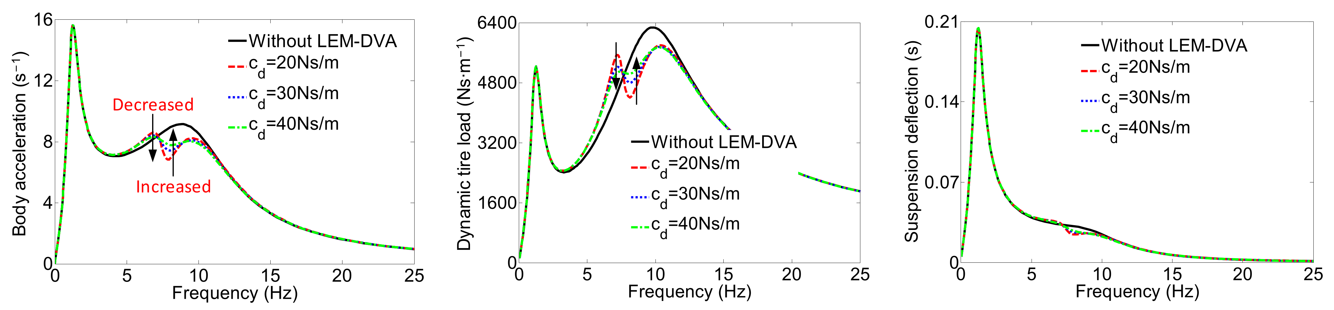
3.2. Parameter Sensitivity Analysis

The introduction of LEM-DVA has changed the system structure. Different structural parameters (md, kd, cd) of LEM-DVA will affect the system dynamic performance [24,25]. Therefore, the effect of structural parameters on the system dynamic performance is investigated to solve the optimal structural parameters. Thus, the wheel vibration energy can be recovered on the premise of improving the dynamic performance.
The amplitude–frequency characteristics of body acceleration, dynamic tire load, and suspension deflection are chosen as the evaluation indexes of dynamic performance. Through Laplacian transform of Equation (12), the amplitude–frequency characteristics of each index under the input of road velocity can be expressed as
J 1 = x ¨ ^ s x ˙ ^ r = s x s x r
J 2 = k t x ^ u x ^ r + c t x ˙ ^ u x ˙ ^ r x ˙ ^ r = k t + c t s s x u x r 1
J 3 = x ^ s x ^ u x ˙ ^ r = 1 s x s x u x r
where s is the Laplacian operator, and ‘^’ represents Laplace transform.
Figure 7, Figure 8 and Figure 9, respectively, show three resonance peaks corresponding to the vibration of the body, LEM-DVA, and wheel. All structural parameters mainly affect the amplitude–frequency characteristics in a frequency band less than 3 Hz, which is dominated by vehicle body vibration. Moreover, the influence on the suspension deflection is not observed in an entire frequency band. Thus, the variations of the peak values of the second and third resonance peaks with the structural parameters are discussed in this study. Figure 7 shows that the peak acceleration of IWM-EV with an LEM-DVA is decreased first and then increased with the rise in mass block (md) in the first resonance peak compared with the IWM-EV without LEM-DVA. Meanwhile, the peak acceleration is increased with the mass block (md) in the second resonance peak, and the change in tire dynamic load is the same as that of body acceleration. Figure 8 reveals that the peak acceleration and dynamic tire load are decreased with the increase in damping values (cd) in the first resonance peak and increased between the first and second resonance peaks. The peak values in the second peak are the same (remained constant with the change in damping value). Figure 9 shows that the peak acceleration and dynamic tire load are decreased with the increase in stiffness (kd) in the first resonance peak and increased in the second resonance peak.
The above analysis indicates that the sensitivity of different dynamic performances (especially ride comfort and road holding) to structural parameters is different. The optimization of structural parameters will be conducted in the next section to coordinate the dynamic performances effectively.

3.3. Parameter Optimization

The parameters to be optimized include md, kd, and cd, and the optimization objectives are ride comfort, road holding, and suspension travel. The optimization process includes two parts: single- and multi-objective optimizations. The single-objective optimization aims to optimize the three objectives separately and obtain the optimization parameters. The multi-objective optimization is a weighted optimization based on single-objective optimization. The objective function of single-objective optimization is defined as
J i P = min k = 1 n P k J i ,   i = 1 , 2 , 3
which represents the minimizing peak value of the amplitude–frequency curve. P k J i is the kth peak value of the amplitude–frequency curve of Ji. The objective function of multi-objective optimization can be expressed as
J min P = min w 1 k = 1 n P k J 1 J 1 P + w 2 k = 1 n P k J 2 J 2 P + w 3 k = 1 n P k J 3 J 3 P ,   i = 1 , 2 , 3
where J i P (i = 1,2,3) is the optimal constant of single-objective optimization shown in Equation (17), and wi (i = 1,2,3) is a weighted coefficient. The unsprung mass has a considerable influence on the wheel performance; thus, w1 = 0.3, w2 = 0.5, and w3 = 0.2 are selected.
Figure 10 shows the optimization results with md = 3.75 kg, cd = 65 Ns/m, and kd = 8860 N/m. The peak acceleration of IWM-EV is increased by 22.6% compared with focus-driven EV. However, the IWM-EV with LEM-DVA is only increased by 6.2%. That is, the LEM-DVA reduces the peak acceleration by 72.6%. In addition, the acceleration amplitude of IWM-EV with LEM-DVA is always lower than that of focus-driven EV between 9 and 25 Hz, while IWM-EV is 11–25 Hz. The peak value of IWM-EV for dynamic tire load is deteriorated by 31.4% compared with focus-driven EV, but 50.2% is improved by LEM-DVA. Moreover, the suspension travel of IWM-EV has not deteriorated significantly compared with focus-driven EV. Therefore, the improvement of LEM-DVA is not particularly observed. The above results show that the optimized structural parameters can effectively improve the dynamic performance of IWM-EV.

3.4. Simulation Analysis

According to the optimization results (md = 3.75 kg, cd = 65 Ns/m, kd = 8860 N/m), a comparative simulation analysis, including dynamic performance and energy regeneration potential, is conducted among focus-driven EV, IWM-EV, and IWM-EV with LEM-DVA. The simulation parameters are consistent with those of Table 1. Taking the stochastic road of Grade B as input excitation, Figure 11 shows the dynamic performance comparison in the time domain, and the specific results are shown in Table 2. Each performance index of IWM-EV deteriorated compared with focus-driven EV, which is reduced by 10.8% (body acceleration), 15.3% (dynamic tire load), and 4.9% (suspension deflection). The results are in agreement with those of Section 2, which show the feasibility and validity of analyzing the influence mechanism of unsprung mass on dynamic performance from the energy flow perspective. Each performance index is improved by 22.2%, 9.4%, and 3.5% compared with IWM-EV with the introduction of the LEM-DVA. Interestingly, the body acceleration is improved by 13.5% compared with focus-driven EV despite the continuous deterioration of dynamic tire load and suspension deflection by 4.5% and 1.2%, respectively. The results are inconsistent with those of the frequency domain. This difference is mainly due to the various focuses of the response RMS and amplitude–frequency characteristics. Specifically, the response RMS reflects the overall average level of performance indexes of amplitude–frequency characteristics in a specific frequency band. The acceleration amplitude for IWM EV with LEM-DVA is only deteriorated at 3~8 Hz but improved at 8–25 Hz (Figure 10). Therefore, the reduction of the RMS of body acceleration is feasible from the overall viewpoint.
Figure 12 shows the power spectral density (PSD) of each performance index. The amplitude of each performance index is the same in the body resonance frequency band, and the performance amplitude of IWM-EV is remarkably increased in the wheel resonance frequency band compared with focus-driven EV but is improved by the LEM-DVA. In addition, the performance amplitude of IWM-EV is increased in the LEM-DVA resonance frequency band, but the peak value is always less than that of IWM-EV. This result is in agreement with those of Figure 10, which indicates the effectiveness of optimization results.
For energy regeneration potential, the IWM-EV is slightly decreased compared with focus-driven EV, and this condition is positively correlated with the increase in body acceleration of IWM-EV. In other words, the reduced power absorbed by the suspension will lead to additional power flow into the vehicle body, which results in increased body acceleration and vice versa. Section 2 has elaborated on this phenomenon. The absorbed suspension vibration power is further reduced considering IWM-EV with LEM-DVA. This reduction is mainly because LEM-DVA absorbs part of the tire vibration power and achieves power diversion, which reduces the relative motion between wheel and body and the vibration power absorbed by suspension.
Overall, the introduction of LEM-DVA reduces the vibration energy regeneration potential of IWM-EV. However, LEM-DVA effectively improves the dynamic performance and achieves coordination between energy regeneration and dynamic performance, which shows the effectiveness of the proposed method in this study.

4. Test Verification

4.1. Structure Implementation

A new structure, which integrates LEMD and LEM-DVA, is proposed to implement the coordination method in this section. Figure 13 shows that LEMD and LEM-DVA comprise a mover and a stator, that is, a linear motor.
The stator for LEMD is connected to the vehicle body, which includes iron core and coil windings. The mover, including steel tube and permanent magnets, is connected to the wheel. Thus, the induced electromotive force (EMF) is generated between the stator and the mover with the relative movement of the vehicle body to the wheel.
The LEM-DVA is fixed to the steel tube of LEMD, which is then fixed to the wheel. Unlike the LEMD, the stator of LEM-DVA is fixed to the steel tube. When the wheel vibrates, the permanent magnet acts as a mover to absorb the vibration of the wheel by compressing elastic material and generates induced EMF with the stator. In addition, two axial sliding bearings (A and B) are installed inside the mover to ensure the axial motion of the permanent magnet and reduce friction. An axial sliding bearing (C) is also observed between the stator and the mover for the same consideration.
Overall, the LEMD can suppress the relative motion of the vehicle body and the wheel while recovering the vibration energy. The LEM-DVA can also absorb the vibration of the wheel and regenerate the vibration energy simultaneously. Thus, the coordination of vibration energy regeneration and dynamic performance can be achieved. Notably, this new structure increases the requirement for assembly space. However, the IWM-EV omits the transmission device and increases the chassis space, which contributes to the feasibility of the structure for application on the IWM-EV.

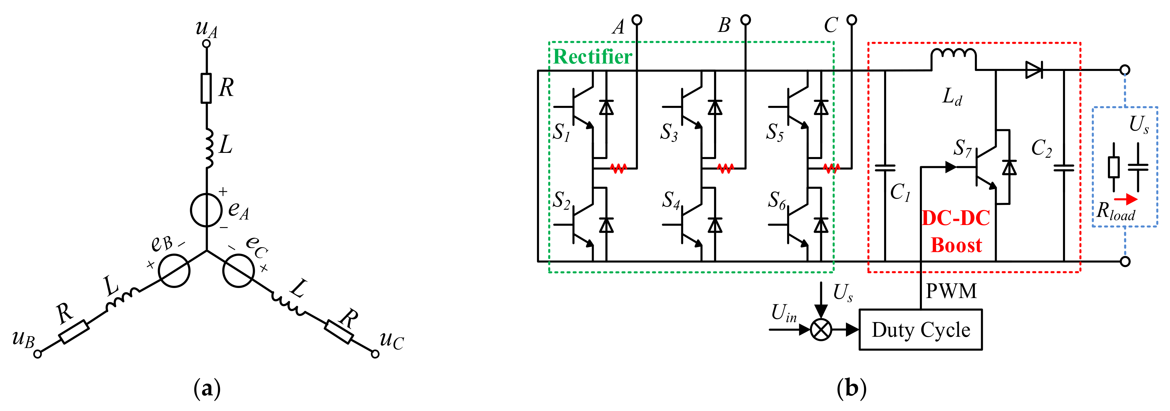
4.2. Design of Energy Regeneration System

The linear motor (LEMD/LEM-DVA) is used to recover the vibration energy (mechanical power), which outputs electric power to the supercapacitor. Except for a small part of the energy dissipated in the coil and iron core, most of the mechanical power is converted to electric power through electromagnetic action. This study assumes that the magnetic circuit is unsaturated, and the resistance, inductance of stator windings are constant. Therefore, Figure 14a shows that if the three-phase windings of linear motor are star-connected and symmetrical in space, then the voltage equation of each phase winding is:
e = R i + L d i d t + R load i
where eA, eB, eC are the the back EMF of windings A, B and C, respectively; iA, iB, iC are the current of windings A, B and C, respectively; R is motor resistance; Rload is load resistance; L is inductance.
The expression of the back EMF and damping force is as follows:
e = k e v r
F damping = k e k t v r / R + R load
where ke is the back EMF coefficient, kt is the thrust coefficient, and vr is the relative velocity of the stator and mover. The parameters of LEMD and LEM-DVA are shown in Table 3.
The energy regeneration system is completed when the linear motor (LEMD/LEM-DVA) is connected with the external energy storage device, that is, the energy storage device is used to replace the external load. As shown in Figure 14, the energy regeneration process mainly includes rectifying, boosting, and charging the energy storage device. The rectification aims to convert the three-phase AC voltage output to DC voltage using the linear motor. The boost circuit is used to amplify the rectified DC voltage to provide higher output voltage than the terminal voltage of the energy storage device to avoid the phenomenon of “dead zone” (in which the damping force of the linear motor is zero when the charging voltage is lower than the terminal voltage of the energy storage device). The energy storage device adopts the supercapacitor due to its wide range of allowable voltage variation for charging. Notably, the capacitor C1 shown in Figure 14b is used to filter the rectified voltage (Uin), and C2 is used to stabilize the voltage. The difference between the output voltage (Us) and the rectified voltage (Uin) is then considered as the input to adjust the duty cycle of the converter.

4.3. Bench Test

Figure 15 shows the structure layout of the bench test, including the PC system, dSPACE system, LEMD, LEM-DVA, electronic load, supercapacitor, current/voltage sensor, oscilloscope, rectifier, booster, and INSTRON 8800 exciter. Specific functions are as follows:
  • The PC system is used to establish the model, determine the system input and output, and observe the simulation results.
  • The dSPACE is responsible for downloading and running the model of the PC system and receiving/outputting signals.
  • The LEMD is used to generate a force to suppress vibration, and the LEM-DVA is used to produce a force to absorb vibration. Both components convert the energy generated by vibration into electrical energy.
  • The electronic load/supercapacitor are, respectively, connected to LEMD and LEM-DVA. Notably, the connection of the electronic load to LEMD and LEM-DVA facilitates testing of the output voltage characteristics of LEMD and LEM-DVA. Meanwhile, the connection of the electronic load to LEMD and LEM-DVA facilitates testing of the energy regeneration characteristics.
  • The current/voltage sensor measures the voltage and current of the load resistance to obtain the energy regeneration power of LEMD and LEM-DVA, respectively (P = U × I). This measurement is different from simulation analysis whose evaluation index of energy regeneration is mechanical power, but the electrical power is adopted in the bench test. The relationship between mechanical and electrical power is conversion efficiency.
  • The oscilloscope is used to observe current and voltage in real time.
  • The booster is used to convert the three-phase AC voltage into DC voltage, and the booster is utilized to amplify the rectified DC voltage to realize a higher output voltage than the terminal voltage of supercapacitors.
  • The INSTRON 8800 is responsible for simulating suspension displacement.
The terminal voltage of supercapacitors has an important impact on the energy regeneration efficiency of linear motors. Taking LEMD as an example, if the external supercapacitor terminal voltage is too large, then the voltage after boosting may still be lower than the supercapacitor terminal voltage and not be able to charge the supercapacitor, resulting in the “dead zone” phenomenon. Therefore, this section will first test the output voltage characteristics of LEMD and LEM-DVA to determine the reasonable supercapacitor terminal voltage. At this time, the LEMD and LEM-DVA are connected with resistance (1 Ω), and the output voltage is obtained by measuring the resistance current. Figure 16a shows the output voltage of LEMD in different excitation frequencies (f) and amplitudes (s) in different velocities (vr = 2π*f*s). The maximum output voltage is close to 80 V at vr = 0.94 m/s (f = 15 Hz and s = 1 cm), which covers the suspension velocity range (−1 m/s~1 m/s) under normal driving state. The maximum output voltage for LEM-DVA is below 24 V at vr = 2.83 m/s (f = 15 Hz and s = 3 cm), which also covers the absorber velocity range (−3 m/s~3 m/s). In addition, the bench test mainly aims to realize the theoretical method and verify the accuracy of theoretical analysis. Therefore, the system parameters and driving conditions (Class B) of the bench test will be similar to those of the simulation analysis in Section 3.4. The relative velocity of the stator and mover on B-grade roads is generally between −0.5 m/s and 0.5 m/s, and that of LEM-DVA is generally between −1 m/s and 1 m/s. Thus, the peak output voltage of LEMD on Class B will not exceed 48 V and LEM-DVA will not exceed 12 V. Thus, 48 and 12 V supercapacitors are, respectively, used for energy regeneration of LEMD and LEM-DVA.
The output voltage of LEMD and LEM-DVA is random in the actual driving process. The boost circuit when the output voltage of LEMD and LEM-DVA is lower than the terminal voltage of each external supercapacitor is needed to boost the voltage to charge the supercapacitor and avoid the “dead zone” phenomenon (Figure 17). The key to boosting voltage is to determine a reasonable duty cycle (β). The duty cycle as shown in Equation (22) is determined by reference [26].
β = k e v r α e b ,   0 v r α e b k e 1 ,   α e b k e < v r
where α is the velocity ratio between the breakpoints of force–velocity curves with and without a step-up chopper; e b is the battery voltage.
Figure 18 shows the regenerated power of IWM-EV with an LEM-DVA. The specific results, which include dynamic performance and regenerated power of IWM-EV and IWM-EV with LEM-DVA, are shown in Table 4. Compared with IWM-EV, the body acceleration of IWM-EV with LEM-DVA is improved by 22.7%, and the dynamic tire load and suspension deflection are 8.29% and 4.93%, respectively. However, the suspension regenerated power is reduced by 24.91%. This result is consistent with that of the simulation result in Section 3.4. That is, the LEM-DVA can improve the system dynamic performances of IWM-EV while maintaining feedback vibration energy.
However, some errors between the experiment and simulation (Table 2), especially the dynamic performances, are found. Taking IWM-EV with LEM-DVA as an example, the body acceleration of bench test is increased by 16.7% compared with that of simulation, and the dynamic tire load and suspension deflection are, respectively, reduced by 13.6% and 7.2%. This reduction is mainly due to the neglected friction between the stator and the mover in the simulation, which increases the system damping force. Thus, the body acceleration is increased, and the tire dynamic load and suspension dynamic travel are reduced under the same driving conditions. Considering regenerated power of suspension or wheel, regeneration potential, which is a theoretical value, is used for simulation. However, power loss is observed in the bench test, which results in actual values (regeneration power). The actual recovered power of LEMD and LEM-DVA, respectively, accounts for 26.6% and 22.5% of the theoretical power.
Overall, the accuracy of the theoretical analysis, the effectiveness of the coordination method, and the feasibility of the designed structure are verified by the bench test.

5. Conclusions

A method is proposed in this study to coordinate the contradiction between vibration energy regeneration and dynamic performance of IWM-EV, and a new structure is introduced to implement the method. The effectiveness of the designed scheme and method is verified by simulation analysis and bench test. The main results are as follows:
  • The influence mechanism of unsprung mass on energy flow and dynamic characteristics is investigated. The increase in unsprung mass allows additional power flow into the wheel, which deteriorates the road holding. The increased unsprung mass reduces the dissipated power of the damper, and additional power flows into the suspension and vehicle body, which exacerbates the body acceleration and suspension travel.
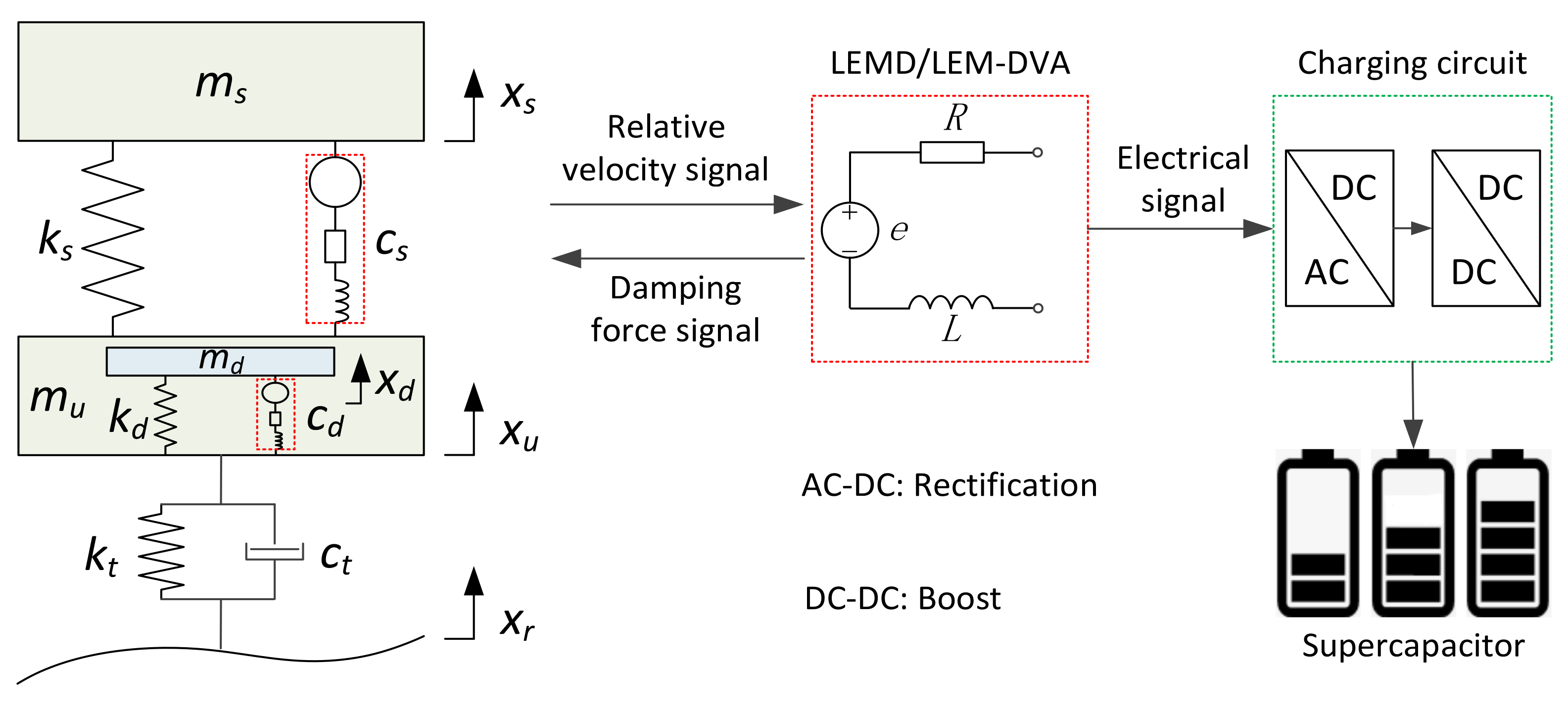
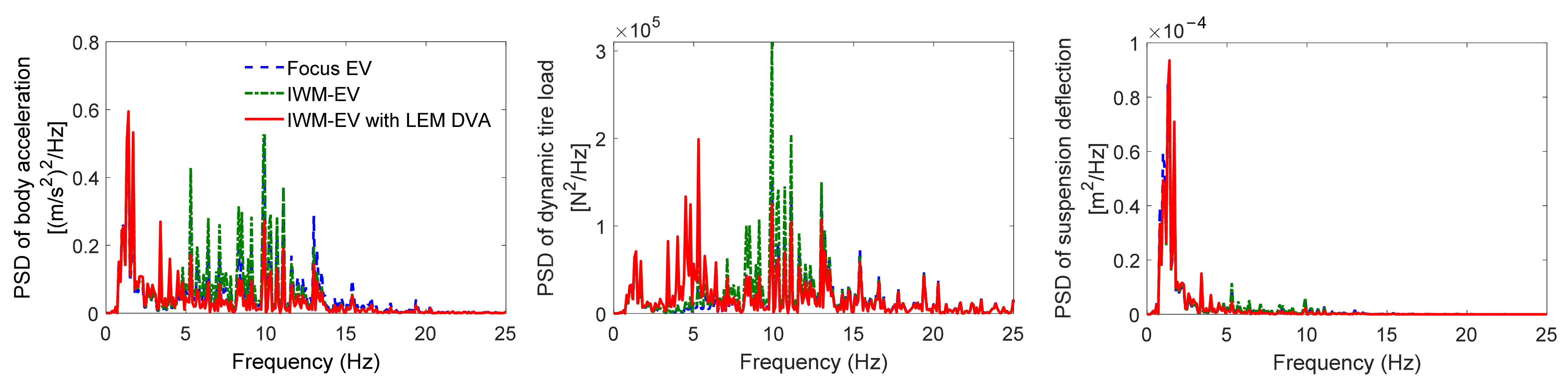
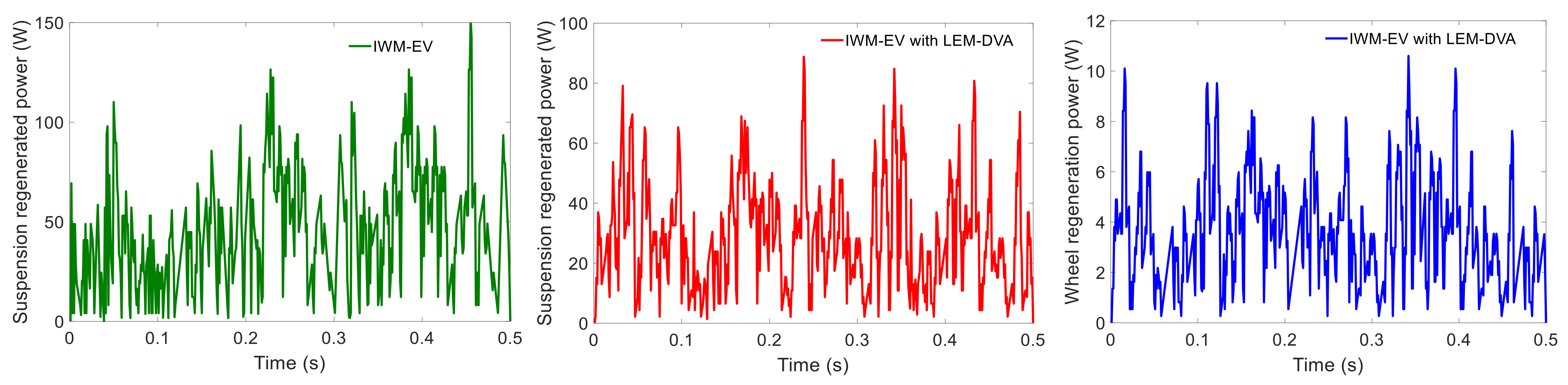
  • A new coordination method, which includes an LEMD and an LEM-DVA, is proposed. The LEMD is employed to recover the mechanical power generated by suspension vibration, and LEM-DVA is used to absorb wheel vibration and convert the mechanical energy into electrical power. The optimal structural parameters of LEM-DVA are obtained, which decreases the body acceleration by 22.2% on a B-grade road compared with that of IWM-EV without LEM-DVA. Moreover, the dynamic tire load and suspension deflection are, respectively, decreased by 9.4 and 3.5%. In addition, the regeneration potential of LEMD and LEM-DVA is 63.8 and 8.26 W, respectively.
  • A new structure, which integrates LEMD and LEM-DVA, is proposed to implement the coordination method. The control system is also designed. The hardware in-the-loop comparative test, including dynamic performance and energy regeneration tests, is conducted. The test results are in good agreement with that of simulation despite the existence of some errors. This finding proves the effectiveness of the new structure in coordinating the vibration energy regeneration and dynamic performance of IWM-EV.

Author Contributions

Conceptualization, C.L.; Methodology, C.Z.; Validation, J.X. All authors have read and agreed to the published version of the manuscript.

Funding

This research was funded by Excellent Backbone Teacher of “Blue Project” in Colleges and Universities in Jiangsu Province, and University Natural Science Research Project in Jiangsu Province (Grant No. 21KJB460037 and 20KJD460007).

Data Availability Statement

No new data were created or analyzed in this study. Data sharing is not applicable to this article.

Conflicts of Interest

The authors declare no conflict of interest.

References

  1. Han, Z.; Zhao, W. Decoupling control of steering and driving system for in-wheel-motor-drive electric vehicle. Mech. Syst. Signal Process. 2018, 101, 389–404. [Google Scholar]
  2. Li, Z.; Zheng, L.; Gao, W.; Zhan, Z. Electromechanical Coupling Mechanism and Control Strategy for In-Wheel-Motor-Driven Electric Vehicles. IEEE Trans. Ind. Electron. 2019, 66, 4524–4533. [Google Scholar] [CrossRef]
  3. Wang, Q.; Li, R.; Zhu, Y.; Du, X.; Liu, Z. Integration design and parameter optimization for a novel in-wheel motor with dynamic vibration absorbers. J. Braz. Soc. Mech. Sci. Eng. 2020, 42, 459. [Google Scholar] [CrossRef]
  4. Yang, F.; Zhao, L.; Yu, Y.; Zhou, C. Analytical description of ride comfort and optimal damping of cushion-suspension for wheel-drive electric vehicles. Int. J. Automot. Technol. 2017, 18, 1121–1129. [Google Scholar] [CrossRef]
  5. Wang, Y.; Li, P.; Ren, G. Electric vehicles with in-wheel switched reluctance motors: Coupling effects between road excitation and the unbalanced radial force. J. Sound Vib. 2016, 372, 69–81. [Google Scholar] [CrossRef]
  6. Shao, X.; Naghdy, F.; Du, H. Reliable fuzzy H∞ control for active suspension of in-wheel motor driven electric vehicles with dynamic damping. Mech. Syst. Signal Process. 2017, 87, 365–383. [Google Scholar] [CrossRef]
  7. Wang, R.; Jing, H.; Yan, F.; Karimi, H.R.; Chen, N. Optimization and finite-frequency H-infinity control of active suspensions in in-wheel motor driven electric ground vehicles. J. Frankl. Inst. 2015, 352, 468–484. [Google Scholar] [CrossRef]
  8. Wu, H.; Zheng, L.; Li, Y. Coupling effects in hub motor and optimization for active suspension system to improve the vehicle and the motor performance. J. Sound Vib. 2020, 482, 115426. [Google Scholar] [CrossRef]
  9. Qin, Y.; He, C.; Shao, X.; Du, H.; Xiang, C.; Dong, M. Vibration mitigation for in-wheel switched reluctance motor driven electric vehicle with dynamic vibration absorbing structures. J. Sound Vib. 2018, 419, 249–267. [Google Scholar] [CrossRef]
  10. Luo, Y.; Tan, D. Study on the Dynamics of the In-Wheel Motor System. IEEE Trans. Veh. Technol. 2012, 61, 3510–3518. [Google Scholar] [CrossRef]
  11. Tian, M.; Gao, B. Dynamics analysis of a novel in-wheel powertrain system combined with dynamic vibration absorber. Mech. Mach. Theory 2021, 156, 104148. [Google Scholar] [CrossRef]
  12. Long, G.; Ding, F.; Zhang, N.; Zhang, J.; Qin, A. Regenerative active suspension system with residual energy for in-wheel motor driven electric vehicle. Appl. Energy 2020, 260, 114180. [Google Scholar] [CrossRef]
  13. Múčka, P. Energy-harvesting potential of automobile suspension. Veh. Syst. Dyn. 2016, 54, 1651–1670. [Google Scholar] [CrossRef]
  14. Zhang, Y.; Guo, K.; Wang, D.; Chen, C.; Li, X. Energy conversion mechanism and regenerative potential of vehicle suspensions. Energy 2017, 119, 961–970. [Google Scholar] [CrossRef]
  15. Zhang, Y.; Chen, H.; Guo, K.; Zhang, X.; Li, S.E. Electro-hydraulic damper for energy harvesting suspension: Modeling, prototyping and experimental validation. Appl. Energy 2017, 199, 1–12. [Google Scholar] [CrossRef]
  16. Shi, D.; Pisu, P.; Chen, L.; Wang, S.; Wang, R. Control design and fuel economy investigation of power split HEV with energy regeneration of suspension. Appl. Energy 2016, 182, 576–589. [Google Scholar] [CrossRef]
  17. Li, Z.; Zuo, L.; Luhrs, G.; Lin, L.; Qin, Y.-X. Electromagnetic Energy-Harvesting Shock Absorbers: Design, Modeling, and Road Tests. IEEE Trans. Veh. Technol. 2012, 62, 1065–1074. [Google Scholar] [CrossRef]
  18. Zuo, L.; Zhang, P. Energy harvesting, ride comfort, and road handling of regenerative vehicle suspensions. J. Vib. Acoust. 2013, 135, 011002. [Google Scholar] [CrossRef]
  19. Abdelkareem, M.A.A.; Xu, L.; Guo, X.; Ali, M.K.A.; Elagouz, A.; Hassan, M.A.; Essa, F.A.; Zou, J. Energy harvesting sensitivity analysis and assessment of the potential power and full car dynamics for different road modes. Mech. Syst. Signal Process. 2018, 110, 307–332. [Google Scholar] [CrossRef]
  20. Ding, R.; Wang, R.; Meng, X.; Chen, L. Energy consumption sensitivity analysis and energy-reduction control of hybrid electromagnetic active suspension. Mech. Syst. Signal Process. 2019, 134, 106301. [Google Scholar] [CrossRef]
  21. Ding, R.; Wang, R.; Meng, X.; Liu, W.; Chen, L. Intelligent switching control of hybrid electromagnetic active suspension based on road identification—ScienceDirect. Mech. Syst. Signal Process. 2021, 152, 107355. [Google Scholar] [CrossRef]
  22. Chen, S.; Tong, J.; Jiang, X.; Wang, Y.; Yao, M. Modeling method for non-stationary road irregularity based on modulated white noise and lookup table method. J. Traffic Transp. Eng. 2020, 20, 171–179. [Google Scholar]
  23. Wang, R.; Jiang, Y.; Ding, R.; Liu, W.; Meng, X.; Sun, Z. Design and experimental verification of self-powered electromagnetic vibration suppression and absorption system for in-wheel motor electric vehicles. J. Vib. Control. 2022, 28, 2544–2555. [Google Scholar] [CrossRef]
  24. Kopylov, S.; Chen, Z.; Abdelkareem, M.A. Back-iron design-based electromagnetic regenerative tuned mass damper. Proc. Inst. Mech. Eng. Part K J. Multi-Body Dyn. 2020, 234, 607–622. [Google Scholar] [CrossRef]
  25. Kopylov, S.; Chen, Z.; Abdelkareem, M.A.A. Implementation of an Electromagnetic Regenerative Tuned Mass Damper in a Vehicle Suspension System. IEEE Access 2020, 8, 110153–110163. [Google Scholar] [CrossRef]
  26. Kim, S.-S.; Okada, Y. Variable Resistance Type Energy Regenerative Damper Using Pulse Width Modulated Step-up Chopper. J. Vib. Acoust. 2001, 124, 110–115. [Google Scholar] [CrossRef]
Figure 1. One-quarter suspension system.
Energies 16 02968 g001
Figure 2. Energy flow of one-quarter suspension system.
Energies 16 02968 g002
Figure 3. Energy flow from road to wheel: (a) Tire absorbed power; (b) Tire damping dissipated power; (c) Wheel vibration power.
Energies 16 02968 g003
Figure 4. Energy flow from wheel to the body: (a) Suspension absorbed power; (b) Damper dissipated power; (c) Body vibration power.
Energies 16 02968 g004
Figure 5. Dynamic characteristics: (a) Body acceleration; (b) Dynamic tire load; (c) Suspension deflection.
Energies 16 02968 g005
Figure 6. Principle of energy conversion.
Energies 16 02968 g006
Figure 7. Sensitivity analysis on md.
Energies 16 02968 g007
Figure 8. Sensitivity analysis on cd.
Energies 16 02968 g008
Figure 9. Sensitivity analysis on kd.
Energies 16 02968 g009
Figure 10. Optimization results.
Energies 16 02968 g010
Figure 11. Dynamic performance comparison in the time domain.
Energies 16 02968 g011
Figure 12. PSD of dynamic performances.
Energies 16 02968 g012
Figure 13. Schematic of the new structure.
Energies 16 02968 g013
Figure 14. Energy regeneration system: (a) Windings circuit of linear motor; (b) Energy regeneration circuit.
Energies 16 02968 g014
Figure 15. Test bench and system. (a) Test bench. (b) Test system.
Energies 16 02968 g015
Figure 16. Output voltage. (a) Output voltage of LEMD. (b) Output voltage of LEM-DVA.
Energies 16 02968 g016
Figure 17. Damping characteristics of PWM step-up chopper damper.
Energies 16 02968 g017
Figure 18. Regenerated power.
Energies 16 02968 g018
Table 1. System parameters.
SymbolsDescriptionIWM-EVFocus EVUnits
msSprung mass330310kg
muUnsprung mass5540kg
ksSpring stiffness19,60019,600N/m
ktTire stiffness200,000200,000N/m
csSuspension damping16951695Ns/m
ctTire damping200200Ns/m
Table 2. Performance comparison (simulation).
IndexFocus EVIWM-EVIWM-EV with LEM-DVA
RMS of body acceleration (m/s2)1.111.230.96
RMS of dynamic tire load (N)666.3768.2696.1
RMS of suspension deflection (m)0.00820.00860.0083
RMS of suspension regeneration potential (W)107.8100.263.8
RMS of wheel regeneration potential (W)--8.26
Table 3. Parameters of LEMD and LEM-DVA.
ParametersUnitsDescriptionLEMDLEM-DVA
keV·s/mBack EMF coefficient88.514.5
ktN/AThrust coefficient95.624.7
R Ω Motor resistance5.11.2
LmHInductance3.31.7
Table 4. Performance comparison (test).
IndexIWM-EVIWM-EV with LEM-DVA
RMS of body acceleration (m/s2)1.451.12
RMS of dynamic tire load (N)655.9601.5
RMS of suspension deflection (m)0.00810.0077
RMS of suspension regenerated power (W)22.6016.97
RMS of wheel regenerated power (W)-1.86
Disclaimer/Publisher’s Note: The statements, opinions and data contained in all publications are solely those of the individual author(s) and contributor(s) and not of MDPI and/or the editor(s). MDPI and/or the editor(s) disclaim responsibility for any injury to people or property resulting from any ideas, methods, instructions or products referred to in the content.

