1. Introduction
The ever-increasing energy needs of humanity are intensifying the exploration and development of new energy sources. Electrical energy consumption is expected to be doubled by 2050 [
1]. Sustainable energies such as solar power, wind power, and other forms of Renewable Energy Sources (RESs) must contribute a noticeable percentage of electrical energy demand. Most RESs generate DC voltage. Among them, solar energy through Photovoltaic (PV) panels is one of the most important sustainable energy sources with DC nature. Power injection from RESs to the conventional AC grid is faced with certain problems. The concept of energy storage has become more important as a result of the increasing penetration of RESs. They can balance the grid. Energy storage is mostly carried out with DC voltage. A rechargeable battery is the main storage form. The DC form of RESs and the storage batteries revive the topic of DC microgrids [
2,
3] and make them a modern trend [
4,
5,
6]. They do not have conventional issues of the AC grid such as harmonics, reactive power control, frequency stability, etc. Taking into account both technical and economic factors, the most suitable DC voltage level appears to be 326 V [
7]. However, other research indicates that a voltage level between 350 V and 380 V could become a standard in the future [
8]. A three-wire DC grid configuration is proposed, consisting of +350 V, −350 V, and a neutral point. Additionally, a 700 V DC grid is being considered as a microgrid for integrating renewable energy sources (RESs). While DC grids have advantages in terms of efficient energy transfer, they may not be compatible with most household devices as most infrastructure is based on alternating current (AC). Therefore, it can be concluded that implementing DC technology rapidly is limited by the need for AC-based power electronics infrastructure.
The lack of a viable business model is another hurdle that must be overcome in order to implement a DC grid. Power electronics manufacturers are hesitant to produce DC appliances and promote the growth of the DC market, while investors are not yet convinced of the potential demand for DC technology. This uncertainty about the DC market is discouraging large market players from investing in DC solutions.
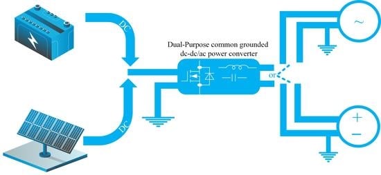
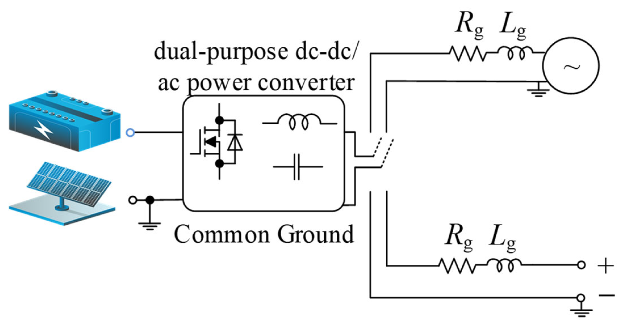
In light of the advantages of DC technology and the challenges associated with its implementation, it is believed that power electronic converters capable of functioning in both DC and AC applications could be a promising solution. The dual-purpose DC-DC/AC approach offers a means to minimize investment risks in DC infrastructure and provide greater flexibility for consumers. This concept is illustrated in
Figure 1 and has been explored in several sources, including [
9,
10,
11,
12].
Design, implementation, and efficient operation of DC infrastructures are topics of discussion. They should be considered in dual-purpose DC-DC/AC power converters as well. One of the key issues to be taken into consideration is protection [
13], and corrosion is one of its important aspects. It results from the electro-chemical process in a concrete structure such as a building. Concrete contains salt. The DC leakage current is conducted by metal and makes it anodic. The reaction between the anodic metal and the existing salt leads to the production of oxygen which makes the environment corrosive. Therefore, the metal slowly corrodes and dissolves the reinforcement. One solution to tackle leakage current is an earth leakage circuit breaker. This can switch off the installation if the leakage current reaches a certain value. In other words, if the leakage current stays below the specified value, the circuit breaker does not operate, and the metal reinforcement is in danger. Even several milliamperes of DC leakage current can create a corrosive environment. The damage of a DC leakage current is 100 times higher than the damage of an AC leakage current of the same size. Hence, using an earth leakage current circuit breaker is not an appropriate idea. Corrosion problems can be solved if leakage currents are prevented from flowing through the earthing facilities. In order to achieve this goal, sources are earthed indirectly through a capacitor diode network. The diodes block the leakage currents as long as the applied voltage remains below the diode voltage. The number of capacitor diode networks depends on the number of decentralized sources. In the case of several decentralized sources, a single ground point is not sufficient. This affects the system grounding configuration, and consequently a greater number of capacitor diode networks is required. Moreover, this solution is suitable for DC power systems. If the dual-purpose DC-DC/AC power converter operates in an AC power grid, another approach is required to suppress AC leakage. This burdens the system.
In most cases, there are numerous methods available for designing the grounding system in an electrical power network, and each of these approaches can lead to varying levels of performance outcomes [
14]. It is important to note that the primary purposes of grounding are for identifying ground faults and ensuring the safety of personnel and equipment [
15]. Low-Voltage (LV) DC microgrids can be grounded through high resistance or low resistance. The ground can be connected either to one of the poles or to the middle point if it is available. Low-resistance grounding means that the grounded wire has a very similar potential to AC grids. The opposite case in DC systems requires only high-resistance grounding and cannot eliminate leakage current, which in turn leads to corrosion problems.
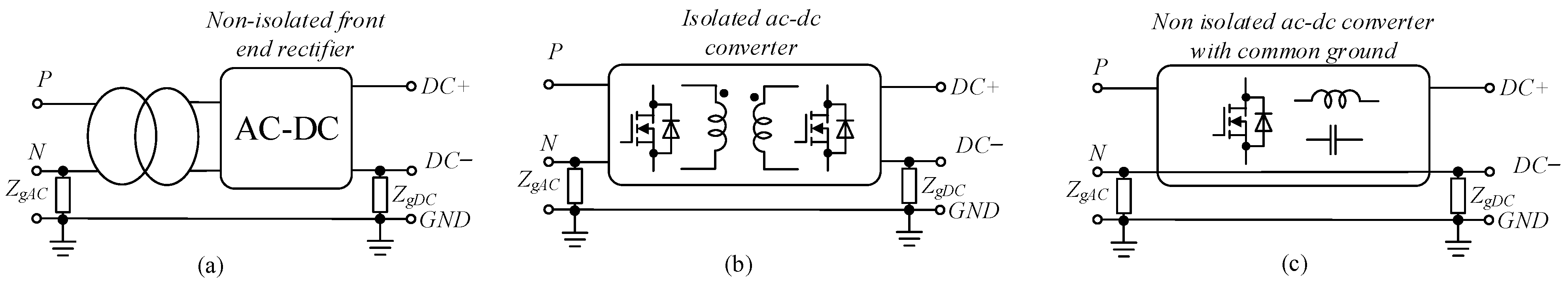
The way of grounding depends on the interconnection between AC and DC grids.
Figure 2 shows different scenarios of DC grids where the grounding can be realized by low impedance on both sides. First of all, power flow between AC and DC microgrids can be provided by low-frequency transformers and non-isolated front-end rectifiers (
Figure 2a).
Figure 2b shows an isolated ac-DC converter. Finally,
Figure 2c shows a non-isolated power electronics interface. The last solution does not have any redundancy. Moreover, it requires DC-AC energy conversion with common ground. The used transformers in the first two solutions impose a high volume to the system and decrease its efficiency. The common-ground architecture is a suitable approach for DC and AC systems in terms of full elimination of the DC and AC leakage currents. It could be a suitable candidate for dual-purpose DC-DC/AC power converters. Furthermore, such types of converter can be used as interfaces between DC and AC grids.
There are many DC-AC converters with common-ground architecture [
16,
17,
18,
19,
20,
21,
22,
23,
24]. They also have the capability of dual-purpose DC-DC/AC operation. The Switched-Capacitor (SC) or Flying Capacitor (FC) solutions [
16,
17] and their derivatives [
18] have common-ground features. However, they cannot realize a boost mode and suffer from inrush current.
Multilevel SC-based structures are presented in [
19,
20,
21,
22,
23,
24]. These structures can also inject power to the grid at an input voltage lower than the peak grid voltage; however, their main shortcoming is inrush currents. Moreover, their voltage-boosting factor is constant.
Meantime, several novel common-ground solutions suitable for dual-purpose application have been already presented [
25,
26,
27].
The main goal of this work is to provide comparative analysis of common-ground solutions suitable for dual-purpose DC-DC/AC applications. Prior to previously presented dual-purpose solutions, the novel common-ground Flying Inductor (FI) DC-AC converter [
28] is selected for design and experimental verification for dual-purpose application. The selected DC-DC/AC power converter is evaluated and compared with existing dual-purpose DC-DC/AC power converters.
The paper is organized as follows.
Section 2 is devoted to the comparison between existing solutions.
Section 3 describes the operation principle of the selected FI solution.
Section 4 is devoted to the components’ design guidelines example.
Section 5 is devoted to the prototype description and experimental verification. Finally, the main design challenges and conclusions are presented and discussed in
Section 6 and
Section 7, respectively.
2. Comparison Study
In this section, the aim is to compare dual-purpose DC-DC/AC power converters with common-ground features.
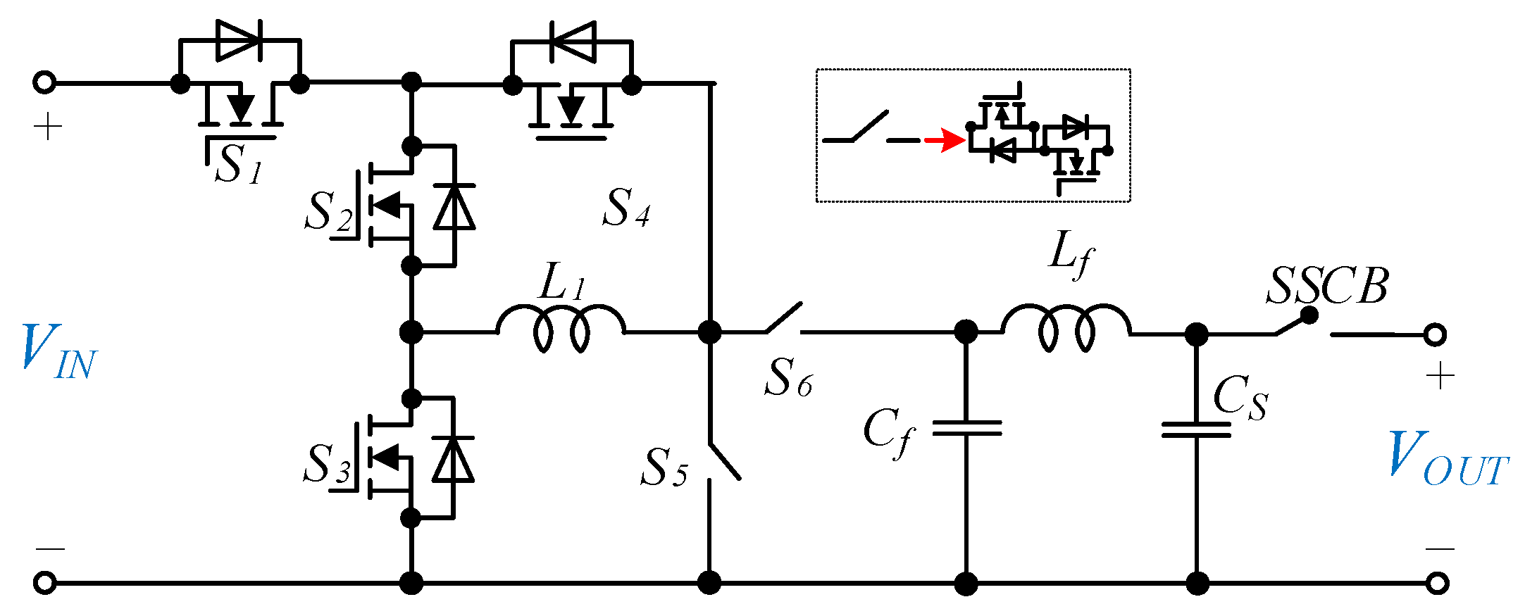
Figure 3 shows the circuit of an FI DC-AC converter presented in [
28], as one of the novel family of FI inverters. By means of this example, we demonstrate that many solutions with additional suppressor capacitor
CS and Solid-State Circuit Breakers (SSCB) for very fast disconnection in case of any emergency can be used for dual-purpose applications. It was shown in [
9].
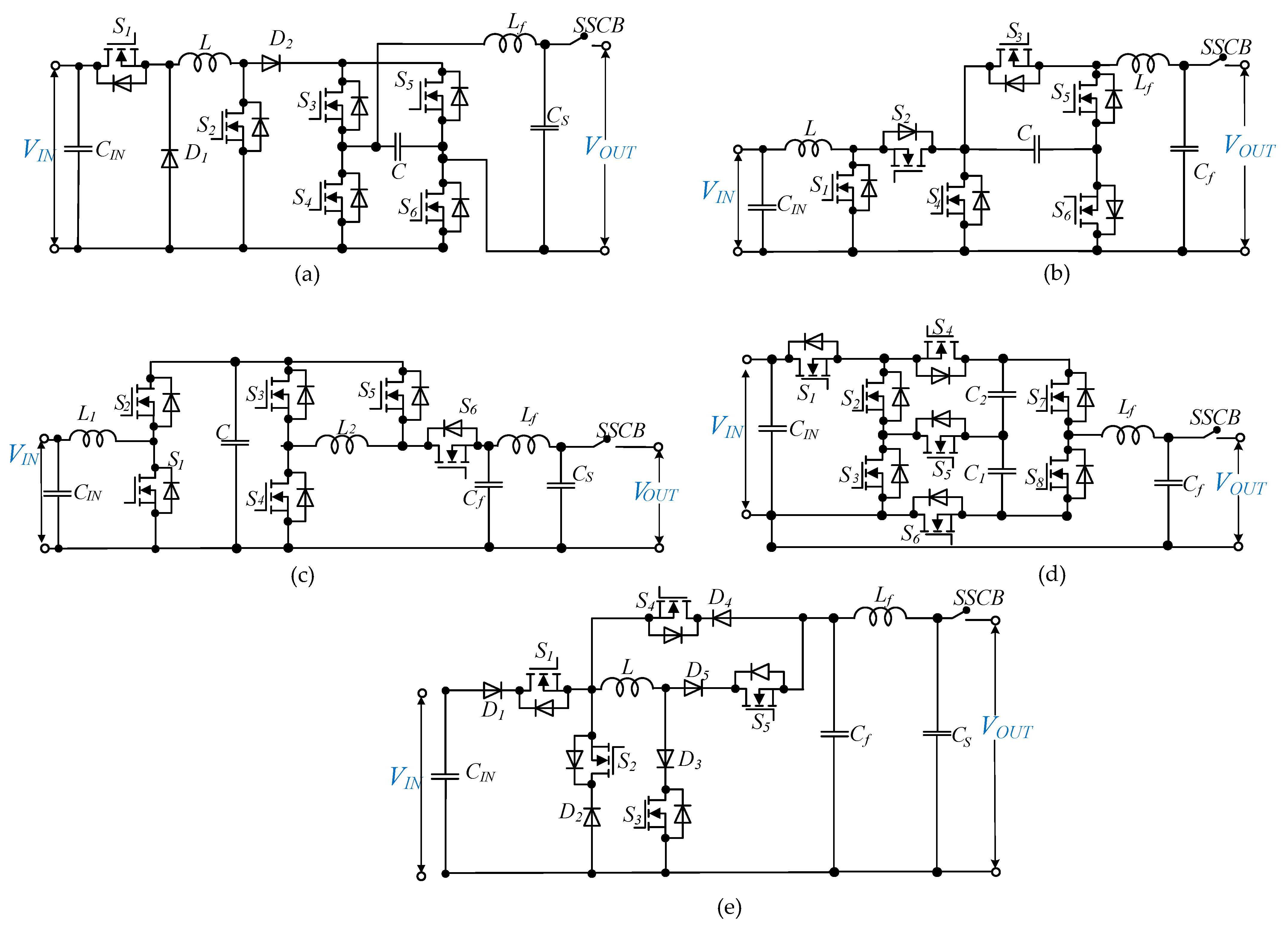
To compare different solutions for dual-purpose DC-DC/AC power conversion, the unfolding circuit with a buck–boost converter from [
9] is used as a reference solution. Other options that are specifically designed for this purpose include the FC power converter in [
25] and the FI-based power converter in [
27]. In addition, many of the latest inverters and multilevel inverters are capable of operating in both DC-DC and DC-AC modes. For the purposes of comparison, the five-level SC-based inverter from [
24] and the FI-based power converter from [
29] are also evaluated. The schematics of these solutions are shown in
Figure 4. All of the solutions are common ground, except for the buck–boost converter and the unfolding circuit from [
9]. While the unfolding circuit can significantly reduce leakage current, it cannot eliminate it entirely.
In [
25], a dual-purpose power converter is introduced. It is based on the FC circuit and operates as a three-level inverter. During DC-DC and DC-AC conversion, a capacitor is used to pump energy into the negative output voltage. On the other hand, the inverter in [
24] is based on the SC circuit and uses two capacitors as voltage sources in the negative half cycle. Although the virtual voltage source concept is used in [
24,
25], they differ in terms of capacitor charging. In [
25], the capacitor charges smoothly through a charging inductor, while in [
24], the capacitors charge directly from the voltage source at the switching frequency, resulting in current spikes. In contrast, the unfolding circuit in [
9] uses a virtual capacitor that functions as a current source.
Similar to the selected dual-purpose FI power converter, the introduced power converters in [
27,
29] are based on FI circuits, and the required energy is pumped from the inductors to the output. Among the compared topologies, the SC power converter in [
24] has a fixed double-voltage boosting capability, while other solutions can operate under a wide range of input voltages.
It is aimed to discuss the advantages and disadvantages of each structure. To reach this goal, it is important to pay attention to the point that each structure is designed, built, and tested under different conditions; hence, it is not possible to make a fair comparison. However, the fundamental waveforms of a typical converter are independent of the component type and electric parameters (e.g., switching frequency and selected semiconductors). To put it differently, the primary wave forms are produced through the fundamental modulation method, which establishes certain overall requirements for component sizing. These requirements involve estimating passive component values, which can be achieved by considering equal current ripples in the inductors and identical voltage ripples across the capacitors.
In (1) and (2) the maximum accumulated energy inside a capacitor and an inductor are calculated, respectively. According to these equations, the volume of a core of an inductor as well as the volume of a capacitor can be estimated:
In (1), Ci and NC are the capacitance of the ith capacitor and the number of capacitors, respectively. Furthermore, represents the peak voltage of the ith capacitor. In (2), Li and NL are the inductance of the ith inductor and the number of inductors, respectively. In addition, is the peak inductor current.
The losses of conductivity in relation to the switch current are directly proportional to the square of the current, and are independent of semiconductors. Total conduction losses can be obtained by (3):
Finally, we can estimate the Total Standing Voltage (
TSV) across the semiconductors:
Based on the above-mentioned points, we provided the same condition for all the selected topologies in the PSIM environment under equal conditions as the following.
The inductors were selected to have a current ripple equal to 20% of their current ratings. With this assumption, the used charging inductor in [
9,
25] is 3.3 mH, the two inductors in the flying inductor power converter in [
27] are 1 mH, the inductor in the flying inductor power converter in [
29] is 1.1 mH, and the inductor in the selected dual-purpose DC-DC/AC power converter is 1 mH.
The capacitors were selected to have a voltage ripple equal to 10% of their voltage ratings. With this assumption, the used capacitor is 10 uF in the FC-based power converter in [
25], is 2 uF in the buck–boost and unfolding circuit in [
9], is 300 uF in the FI-based power converter in [
27], and is 1600 uF for
C1 and 680 uF for
C2 in the SC-based inverter in [
24].
The output filter for the selected dual-purpose DC-DC/AC power converter, the FI-based power converter in [
27], the FI-based power converter in [
29], and the buck–boost and unfolding circuit in [
9] is a CL type. The output filter for the FC-based power converter in [
25] and the switched-capacitor inverter in [
24] is a CL type. In all the compared topologies, the output filter capacitor is 3.3 uH. It should be noted that the used capacitor in the unfolding circuit acts as the output filter capacitor and is equal to 2 uF. There is no additional output filter capacitor in this topology. In the selected topology, the inductance of the output filter inductor is 500 uH. It results in 2.53% Total Harmonic Distortion (THD) in the output current. Hence, the output filter inductors are selected to have the same THD in the output current. Based on this assumption, the output filter inductor is 750 uH for the buck–boost and unfolding circuit in [
9], is 1700 uH for the FC-based power converter in [
25], is 1 uH for the FI-based power converter in [
27], is 700 uH for the FI-based power converter in [
29], and is 2000 uH for the SC-based power converter in [
24].
The parameters in
Table 1 were considered for all the compared topologies to simulate the same conditions.
The power switches in the circuit were assumed to have an on-state resistance of 0.028 Ω, which is the internal resistance of the NVHL020N120SC1 switch, a type of N-channel MOSFET power switch with a body diode. In contrast, the power switches used in a previous power converter design (referenced as [
29]) were Insulated Gate Bipolar Transistor (IGBT) power switches without body diodes, which limit the current to flow in only one direction. MOSFETs, on the other hand, have bidirectional current flow capability inherently. To account for the unidirectional current flow in the IGBT-based design, a diode was added in series with the power switch in the simulation. For power diodes, the on-state resistance (
Ron,D) was assumed to be 0.05 Ω, and the forward voltage (
Vfw,D) was assumed to be 0.65 V in the circuit models.
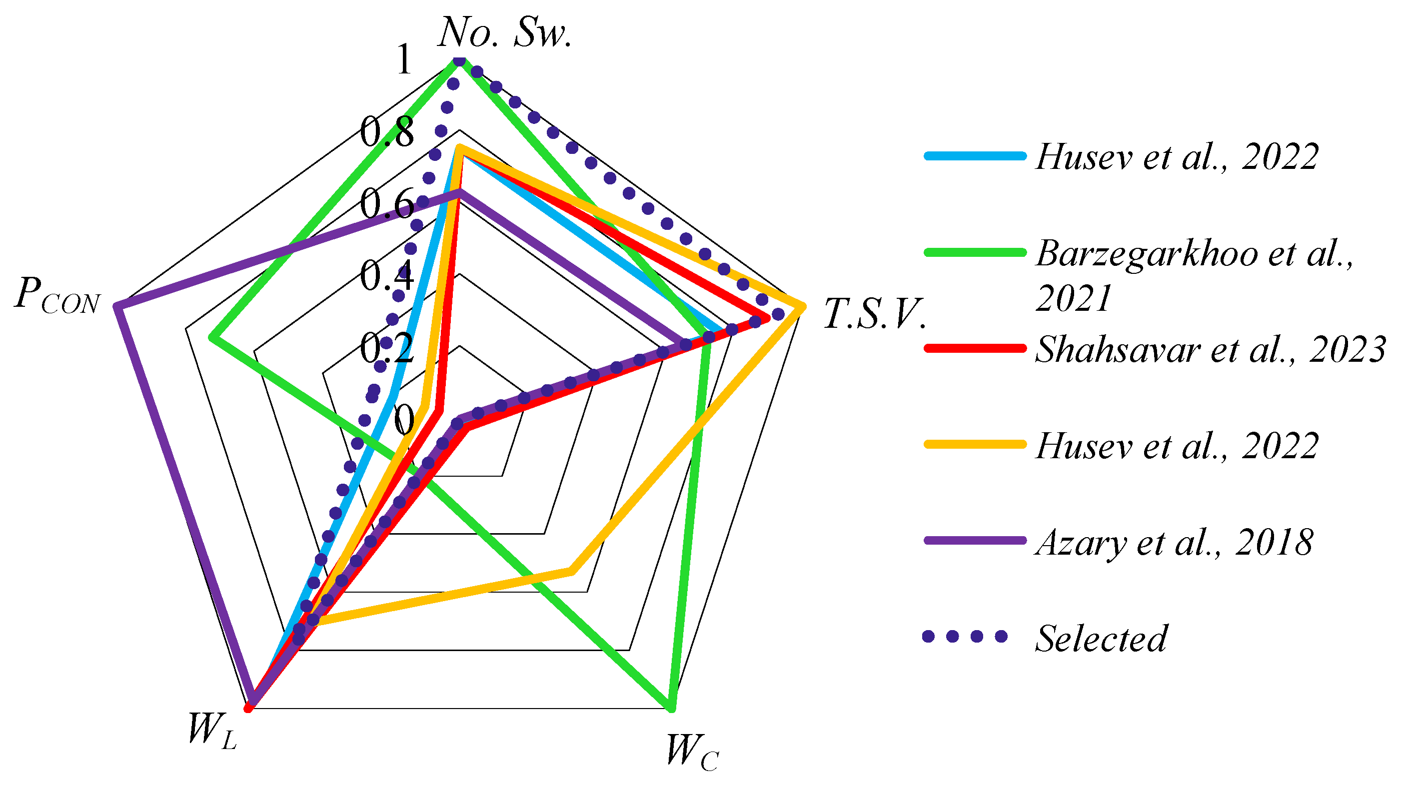
The comparison between different circuit designs focused on several key factors, including the accumulated energy of capacitors (
WC), the accumulated energy of inductors (
WL), the Total Standing Voltage (TSV) of the semiconductors, conduction losses of the semiconductors (
PCON), and the number of power switches used (
NSW). It has been previously discussed in reference [
25] that a smaller number of power switches does not necessarily result in higher efficiency, and this issue will also be explored in the current discussion.
Figure 5 presents a radar chart comparing the different circuit topologies based on their calculated parameters shown in per unit values. The inverter introduced in reference [
24] uses an SC circuit and has the highest capacitor value among the compared designs, resulting in high accumulated energy in the capacitors. However, this topology also has significant conduction losses. Switched-capacitor circuits are susceptible to current spikes that occur when the capacitors are being charged, causing inrush currents to pass through the power switches in the charging path, leading to higher current stress and power losses. As the output power increases, the magnitude of these current spikes becomes higher, potentially damaging the power switches. Therefore, SC-based solutions are not suitable for high-power applications. The FI power converter in [
29] has the highest value of conduction losses due to power losses across the series-connected power diodes with the power switches. In contrast, the selected dual-purpose DC-DC/AC power converter, the FC-based power converter in [
25], and the buck–boost unfolding circuit in [
9] have the lowest accumulated energy in the capacitors. The selected dual-purpose DC-DC/AC power converter and the introduced power converter in [
29] use FI architecture, and the filter capacitor is the only capacitor used in their configuration. The dual-purpose converters in [
9,
25] use a pseudo DC-link approach, which significantly reduces the capacitor size while maintaining good grid current quality. In terms of accumulated energy inside the inductors, the selected dual-purpose power converter stands out among the compared topologies, while the FI-based power converter introduced in [
29] ranks highest. Regarding TSV, the introduced flying inductor dual-purpose converter in [
27] has the highest voltage stress across its power switches.
6. Main Design Challenges
This section is devoted to the feasibility study of the selected converter for experimental verification. The unique feature of the FI power converter is that it has a continuous current in the inductor-charging path, unlike SC and FC power converters where the capacitor charge current is discrete. This requires the availability of a path to allow the inductor current to flow. Therefore, the biggest challenge in an FI converter is to ensure a smooth transition between the switches, which can be achieved through appropriate tuning of the dead time. This issue becomes more complicated when using a four-quadrant power switches arrangement, where the anti-parallel diode of each power switch is blocked by the other power switch.
If the dead time between the switches is too high, the inductor current will be obstructed for a brief period, leading to a substantial voltage surge across the switches. This surge will increase switching losses, decrease efficiency, and may harm the switches. To avoid this voltage spike issue, a snubber capacitor and varistor can be used as a solution, but this will add extra components, increase costs, and create additional losses. When the dead time between the switches is too low, the power switches will be in the on state, creating a quasi-short circuit. Although this limits the voltage surge across the switches, it also increases conduction losses and reduces efficiency, resulting in an increase in input current. Therefore, it is important to balance conduction losses and switching losses by finding an optimal dead-time value. This can be achieved by setting the dead time to different values and measuring efficiency using a power analyzer. Once the optimal point is found, the microcontroller can be used to adjust the dead time to the exact value.
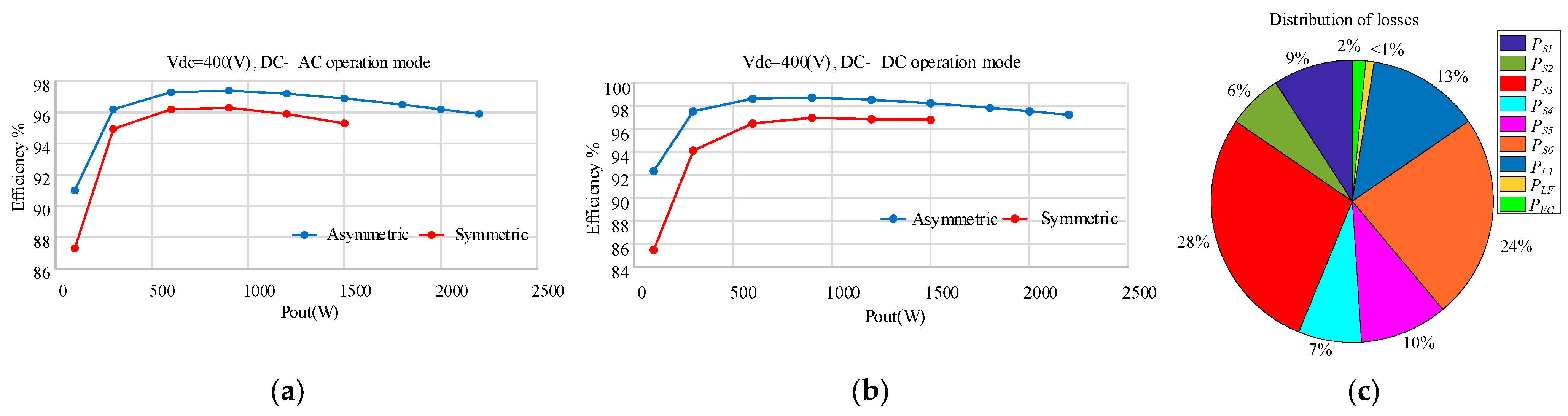
The efficiency curve of the dual-purpose DC-DC/AC power converter operating in DC-AC mode with a 400 V input voltage is depicted in
Figure 15a. The efficiency diagram is presented in two modes: buck–boost (symmetric) and buck (asymmetric). From the figure, it is evident that the efficiency is higher in the buck mode compared to the buck–boost mode. By examining
Figure 15a, it is apparent that the maximum efficiency for an output power of 0.8 kW is 97.5% in buck mode and 96.4% in buck–boost mode. In addition to
Figure 15a,
Figure 15b depicts the efficiency curves of the selected converter in DC-DC operating mode with a 400 V input voltage. It is evident from this figure that the maximum efficiency at an output power of 1 kW is approximately 98.6% for the buck operation state and about 97% for the buck–boost mode.
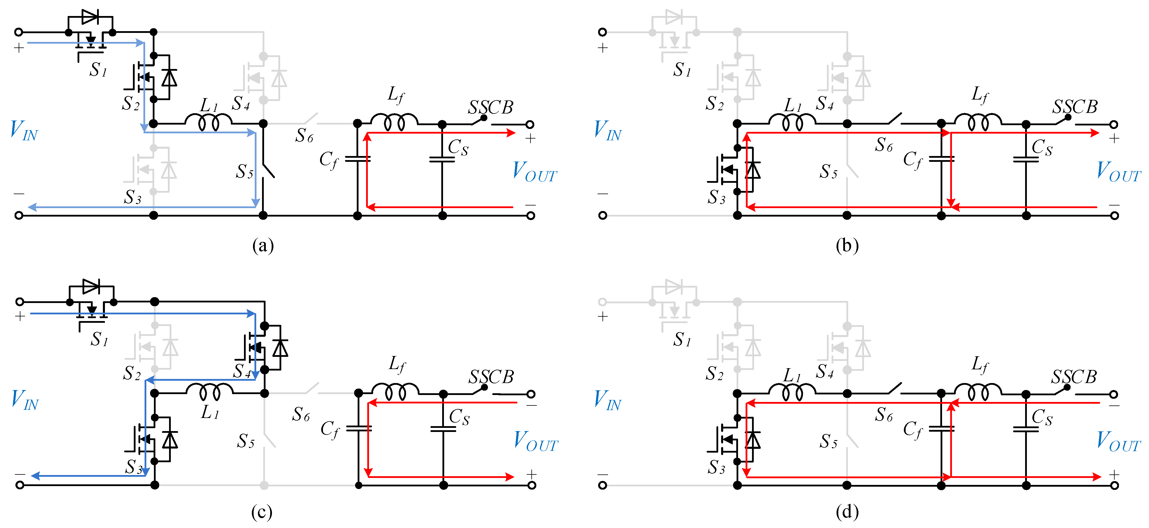
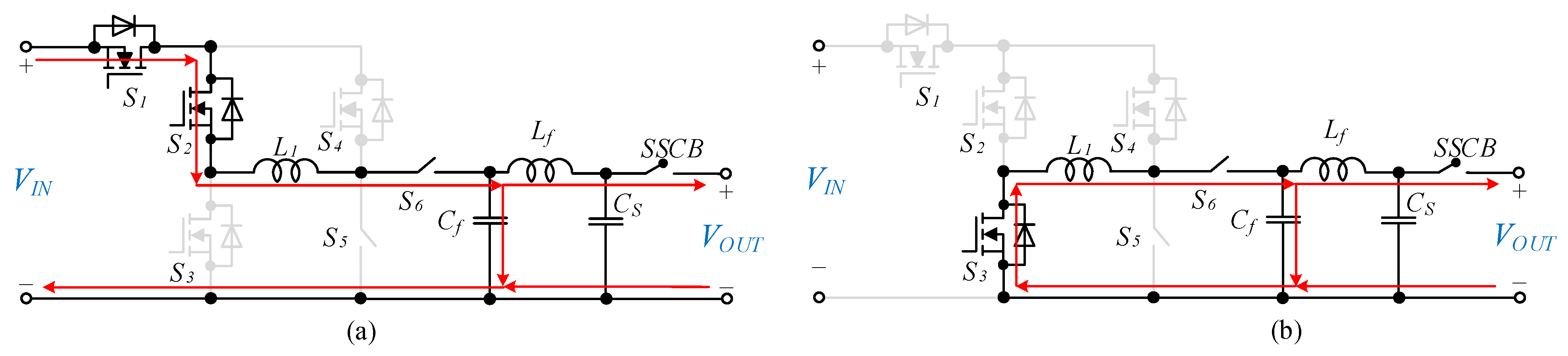
The recorded efficiency was based on the proper dead-time tuning. According to
Figure 6, during the positive half cycle, the inductor undergoes a charging process via
S5 and a discharging process via
S6. In contrast, during the negative half cycle, the charging and discharging of the inductor are conducted through
S4 and
S6, respectively. To ensure that the current in the inductor is continuous while transitioning between the charging and discharging modes, it is imperative to establish an appropriate dead time between
S5 and
S6 and between
S4 and
S6. However, since the SiC power switches have inherent delays, as well as additional delays imposed by the gate driver, a dead time of zero is optimal for these mentioned power switches. On the other hand, the optimum dead time between other power switches has been determined to be 180 nS.
Figure 15c displays a pie chart indicating the percentage of losses for each converter element. The power losses of power switches are the sum of
PCON (as written in (3)), and the switching losses (
PSW) in (28) in which
IS and
Vs indicate the current and voltage stress of
ith power switch, and
N is the number of the used power switches. The conduction losses of the used inductors and the output filter capacitor are written in (29) and (30), respectively. In these equations,
ESRL,
Irms,L,
ESRC, and
Irms,C refer to the Equivalent Series Resistance of an inductor, RMS current of an inductor, the Equivalent Series Resistance of the filter capacitor, and RMS current of the filter capacitor, respectively.
Table 3 gives additional information to calculate the power losses of each component.


 ,
, 


