
A Study on Weight Reduction and High Performance in Separated Magnetic Bearings

Abstract
:1. Introduction
2. Analysis of Existing Model Specifications
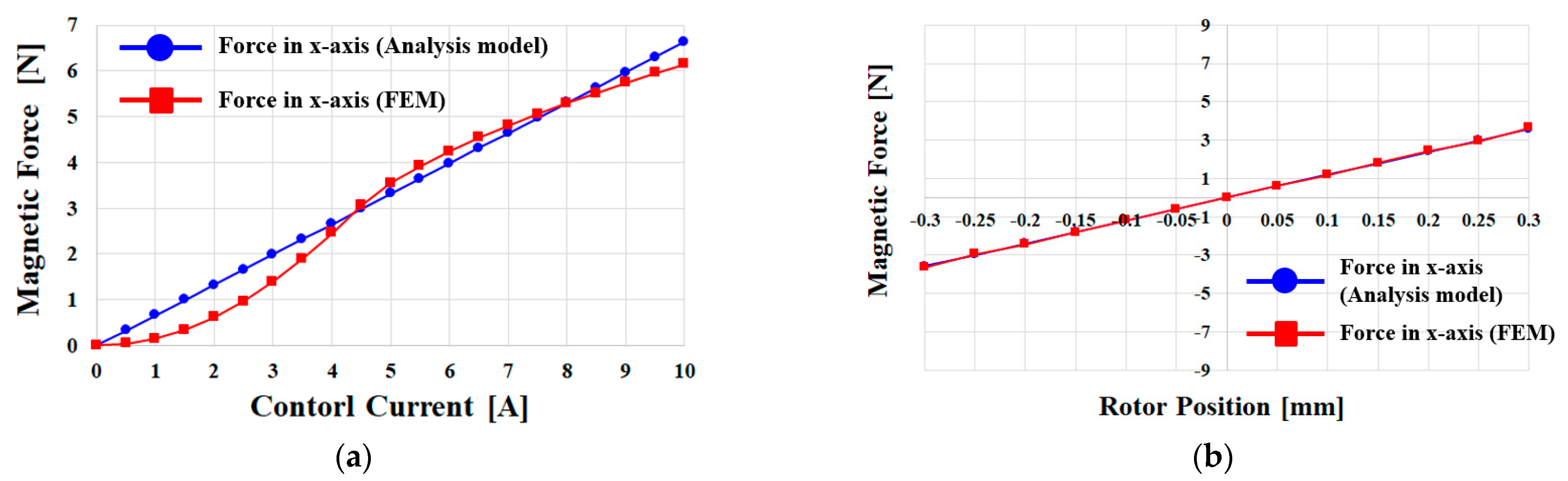
3. Performance Analysis of the STMB
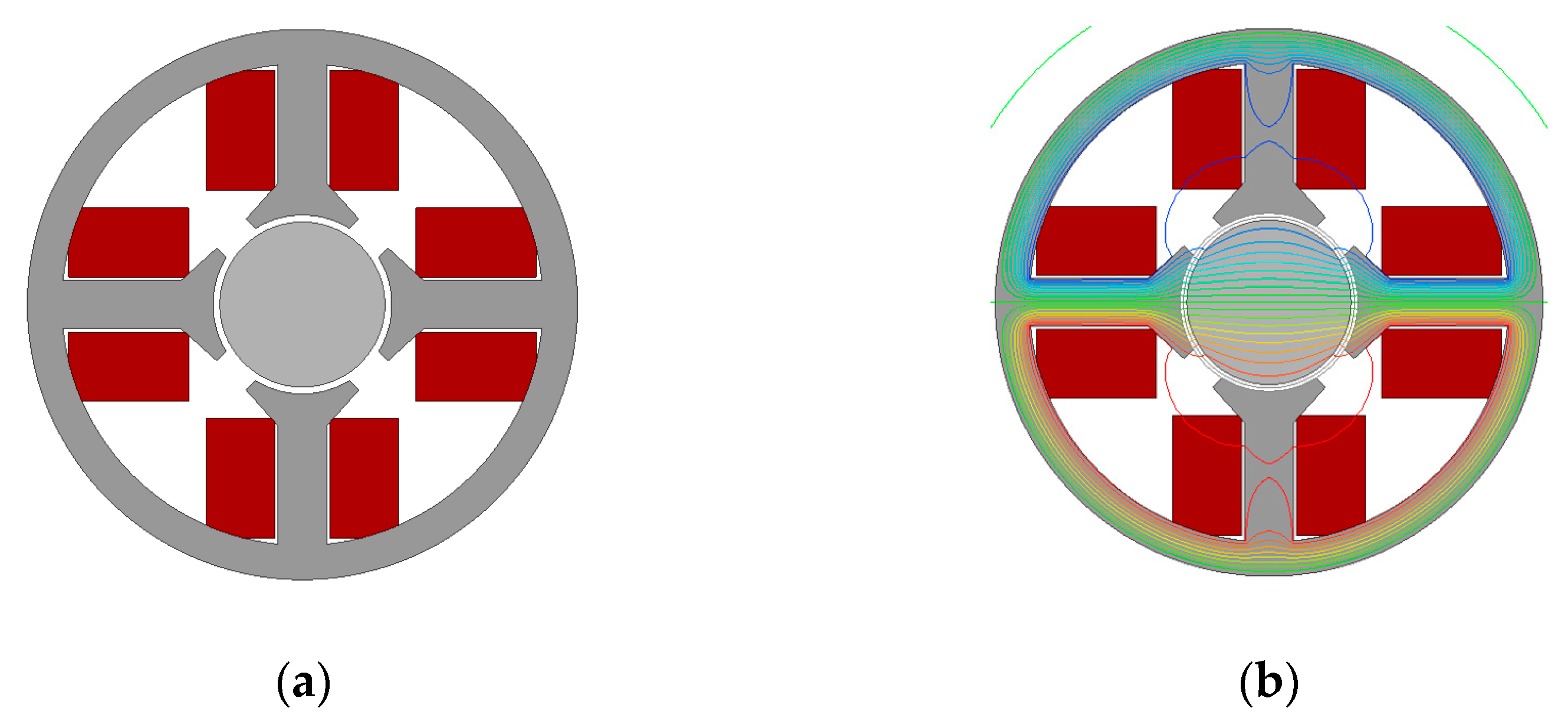
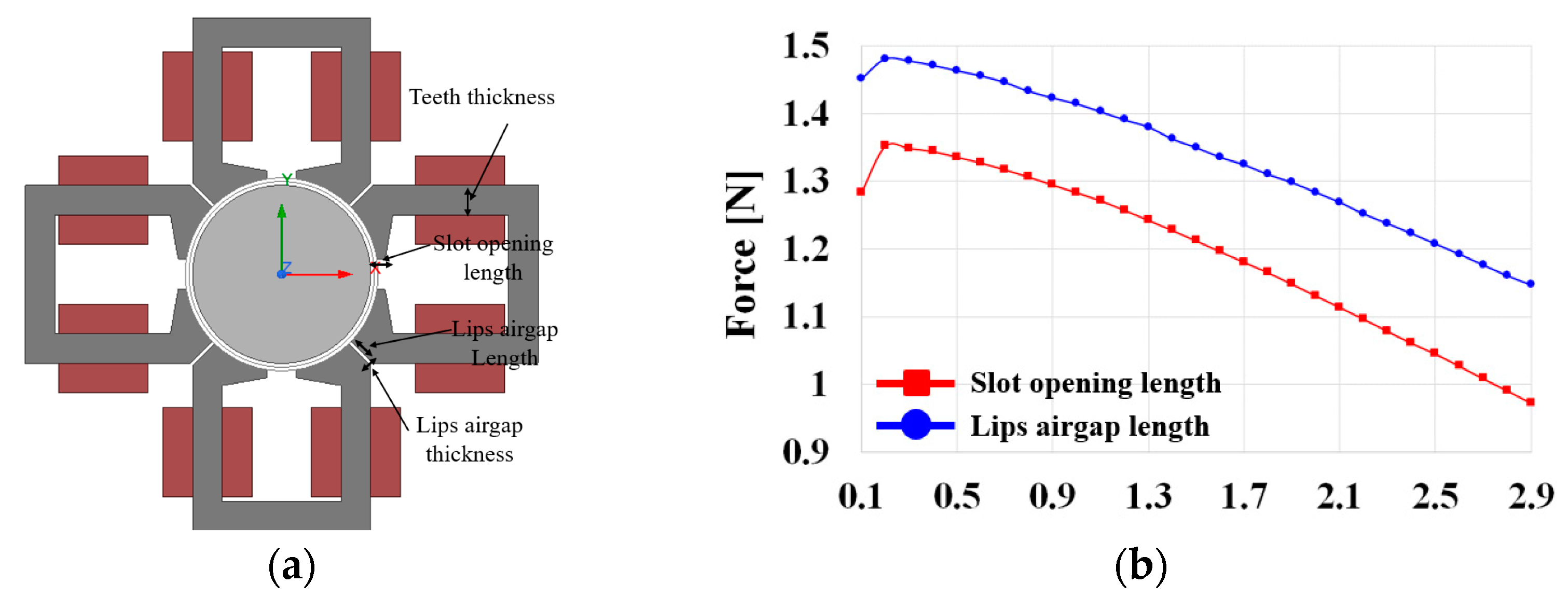
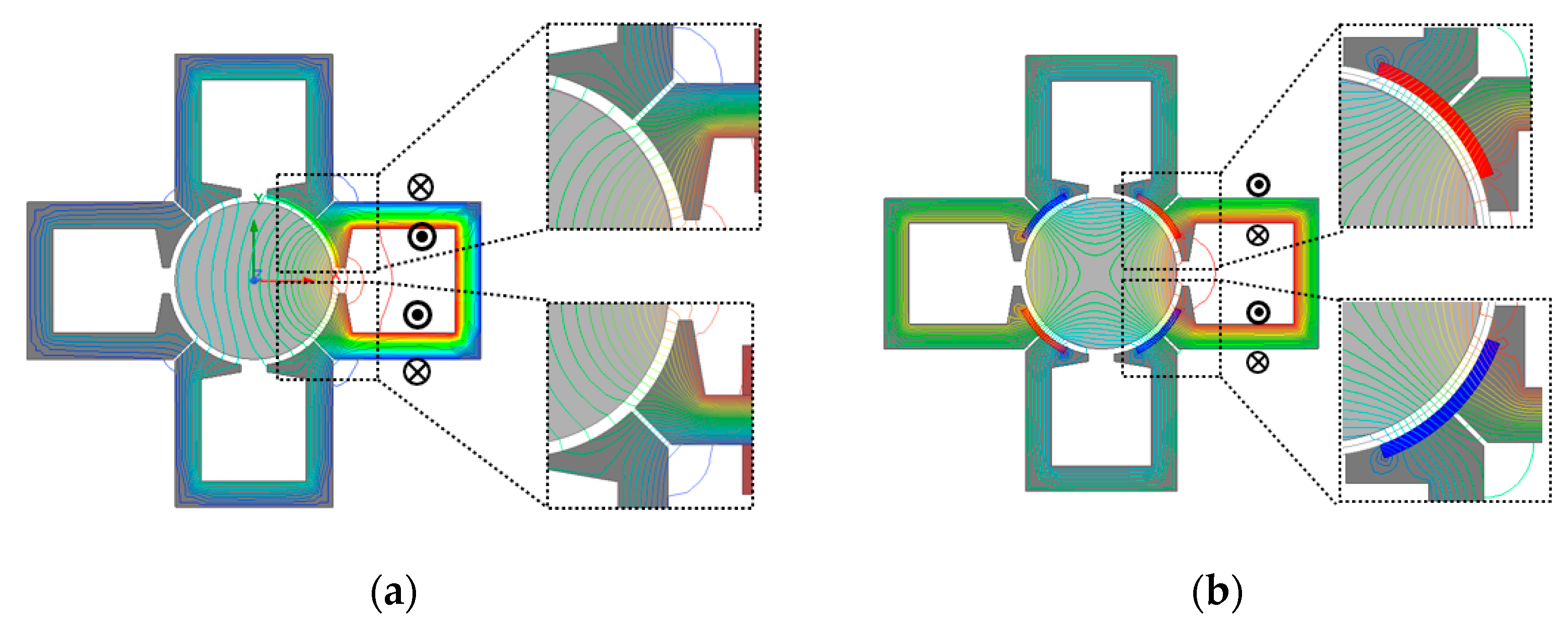
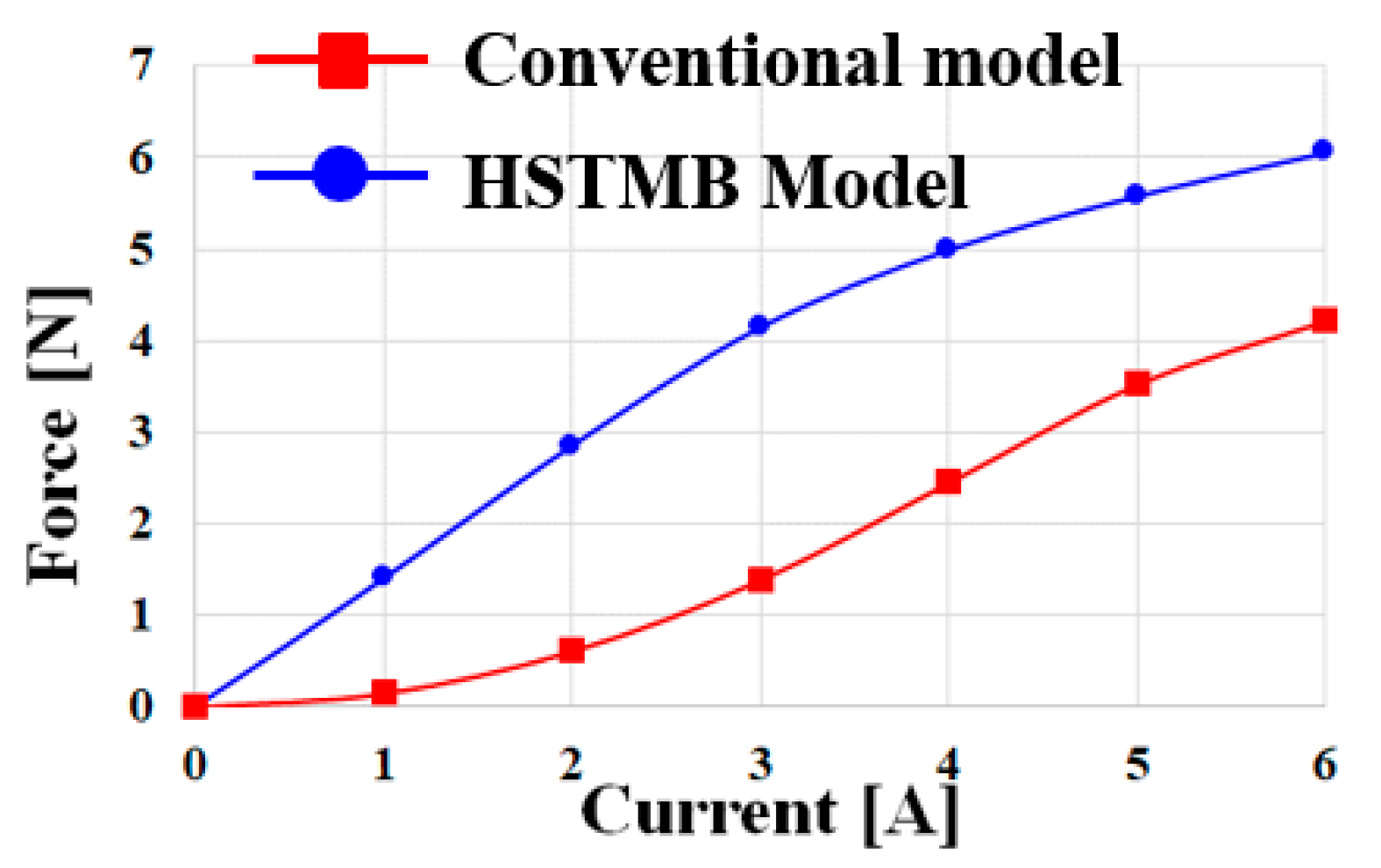
4. Hybrid STMB
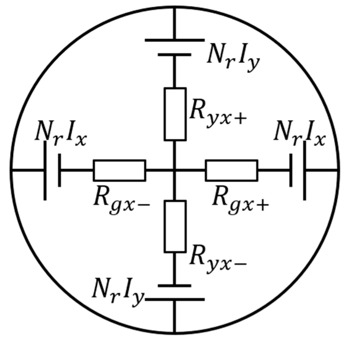
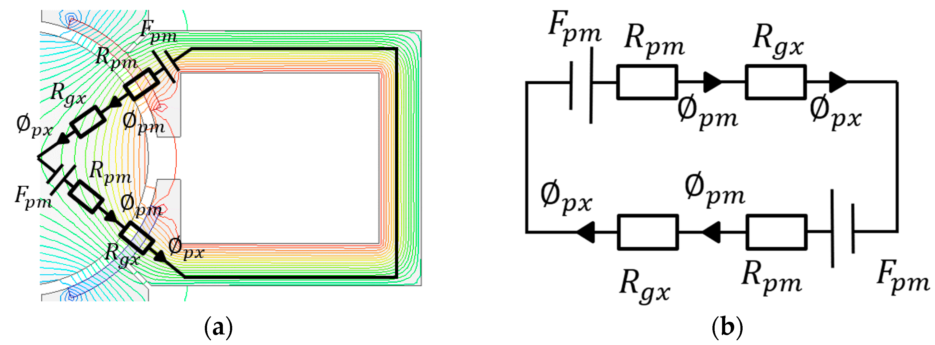
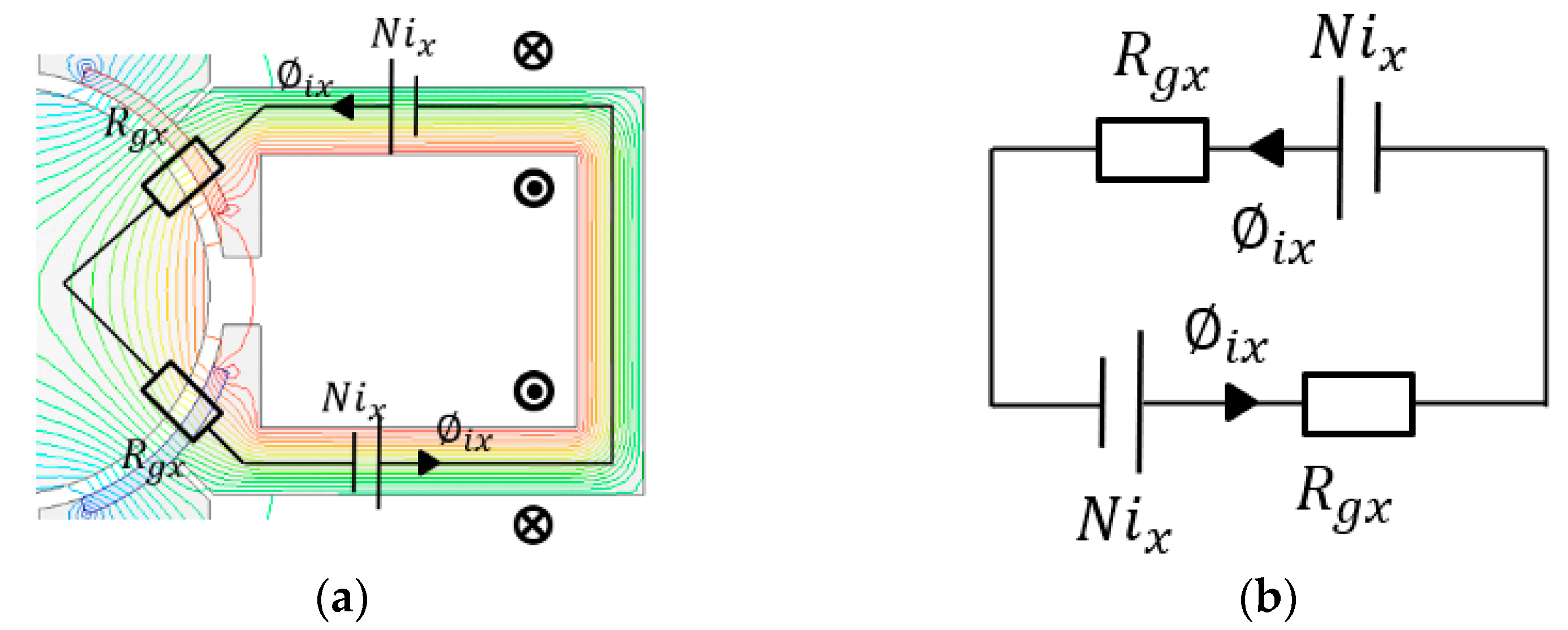
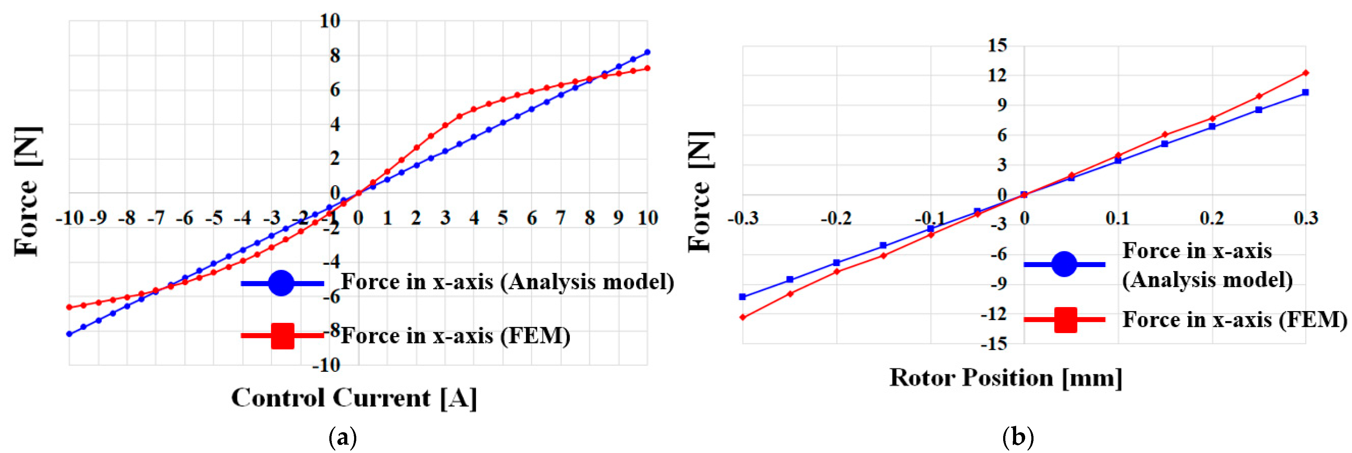
5. Magnetic Equivalent Circuit of the HSTMB
6. Conclusions
Author Contributions
Funding
Data Availability Statement
Conflicts of Interest
References
- Wang, X.; Zhang, Y.; Gao, P. Design and Analysis of Second-Order Sliding Mode Controller for Active Magnetic Bearing. Energies 2020, 13, 5965. [Google Scholar] [CrossRef]
- Rao, P.N.; Devarapalli, R.; García Márquez, F.P.; Malik, H. Global Sliding-Mode Suspension Control of Bearingless Switched Reluctance Motor under Eccentric Faults to Increase Reliability of Motor. Energies 2020, 13, 5485. [Google Scholar] [CrossRef]
- Liu, G.; Liu, X. Integrated Design of a High Speed Magnetic Levitated Brushless Direct Current Motor System. Energies 2018, 11, 1236. [Google Scholar] [CrossRef] [Green Version]
- Siamaki, M.; Storey, J.G.; Wiesehoefer, L.; Badcock, R.A. Design, Build, and Evaluation of an AC Loss Measurement Rig for High-Speed Superconducting Bearings. Energies 2022, 15, 1427. [Google Scholar] [CrossRef]
- Duan, R.; Liao, Y.; Yang, L.; Song, E. Faulty Bearing Signal Analysis With Empirical Morphological Undecimated Wavelet. IEEE Trans. Instrum. Meas. 2022, 71, 3508711. [Google Scholar] [CrossRef]
- Trinh, M.H.; Van Tran, Q.; Ahn, H.-S. Minimal and Redundant Bearing Rigidity: Conditions and Applications. IEEE Trans. Autom. Control. 2020, 65, 4186–4200. [Google Scholar] [CrossRef]
- Wang, H.; Liu, K.; Wei, J.; Hu, H. Analytical Modeling of Air Gap Magnetic Fields and Bearing Force of a Novel Hybrid Magnetic Thrust Bearing. IEEE Trans. Magn. 2021, 57, 4900107. [Google Scholar] [CrossRef]
- Zhao, S.; Zelazo, D. Bearing Rigidity and Almost Global Bearing-Only Formation Stabilization. IEEE Trans. Autom. Control. 2016, 61, 1255–1268. [Google Scholar] [CrossRef] [Green Version]
- Xu, J.; Chen, R.; Hong, H.; Yuan, X.; Zhang, C. Static Characteristics of High-Temperature Superconductor and Hydrodynamic Fluid-Film Compound Bearing for Rocket Engine. IEEE Trans. Appl. Supercond. 2015, 25, 3601908. [Google Scholar] [CrossRef]
- Yamagishi, K. Optimum Design of Integrated Magnetic Bearing Using Multiple HTS Bulk Units. IEEE Trans. Appl. Supercond. 2019, 29, 6801505. [Google Scholar] [CrossRef]
- Zhang, T.; Bao, P. Design of the Six-Pole Hybrid Magnetic Bearing with Separated Magnetic Circuit to Generate Symmetrical Levitation Force. IEEE Trans. Appl. Supercond. 2021, 31, 5205804. [Google Scholar] [CrossRef]
- Jiang, H.; Su, Z.; Wang, D. Analytical Calculation of Active Magnetic Bearing Based on Distributed Magnetic Circuit Method. IEEE Trans. Energy Convers. 2021, 36, 1841–1851. [Google Scholar] [CrossRef]
- Zhang, T.; Wang, Z. Structure and Levitation Force Characteristics Analysis for Novel Radial Hybrid Magnetic Bearing. IEEE Trans. Appl. Supercond. 2021, 31, 0602705. [Google Scholar] [CrossRef]
- Han, B.; Zheng, S.; Li, H.; Liu, Q. Weight-Reduction Design Based on Integrated Radial-Axial Magnetic Bearing of a Large-Scale MSCMG for Space Station Application. IEEE Trans. Ind. Electron. 2017, 64, 2205–2214. [Google Scholar] [CrossRef]
- Ju, J.; Xu, P.; Li, S.; Xu, T.; Ju, F.; Du, J. Design and Optimization Method with Independent Radial and Axial Capacity for 3-DOF Magnetic Bearings in Flywheel. Energies 2023, 16, 483. [Google Scholar] [CrossRef]
- Zhang, W.; Wang, Z. Accurate Modeling and Control System Design for a Spherical Radial AC HMB for a Flywheel Battery System. Energies 2023, 16, 1973. [Google Scholar] [CrossRef]
- Haidl, P.; Buchroithner, A. Design of a Low-Loss, Low-Cost Rolling Element Bearing System for a 5 kWh/100 kW Flywheel Energy Storage System. Energies 2021, 14, 7195. [Google Scholar] [CrossRef]
- Le, Y.; Sun, J.; Han, B. Modeling and Design of 3-DOF Magnetic Bearing for High-Speed Motor Including Eddy-Current Effects and Leakage Effects. IEEE Trans. Ind. Electron. 2016, 63, 3656–3665. [Google Scholar] [CrossRef]
- Fang, J.; Xu, S. Effects of Eddy Current in Electrical Connection Surface of Laminated Cores on High-Speed PM Motor Supported by Active Magnetic Bearings. IEEE Trans. Magn. 2015, 51, 8207604. [Google Scholar] [CrossRef]
- Prasad, K.N.V.; Narayanan, G. Electromagnetic Bearings With Power Electronic Control for High-Speed Rotating Machines: Review, Analysis, and Design Example. IEEE Trans. Ind. Appl. 2021, 57, 4946–4957. [Google Scholar] [CrossRef]
- Le, Y.; Wang, K. Design and Optimization Method of Magnetic Bearing for High-Speed Motor Considering Eddy Current Effects. IEEE ASME Trans. Mechatron. 2016, 21, 2061–2072. [Google Scholar] [CrossRef]
- Schuck, M.; Nussbaumer, T.; Kolar, J.W. Characterization of Electromagnetic Rotor Material Properties and Their Impact on an Ultra-High Speed Spinning Ball Motor. IEEE Trans. Magn. 2016, 52, 8204404. [Google Scholar] [CrossRef]
- Looser, A.; Kolar, J.W. An Active Magnetic Damper Concept for Stabilization of Gas Bearings in High-Speed Permanent-Magnet Machines. IEEE Trans. Ind. Electron. 2014, 61, 3089–3098. [Google Scholar] [CrossRef]
- Song, S.-W.; Yang, I.-J.; Lee, S.-H.; Kim, D.-H.; Kim, K.S.; Kim, W.-H. A Study on New High-Speed Motor That Has Stator Decreased in Weight and Coreloss. IEEE Trans. Magn. 2021, 57, 8201105. [Google Scholar] [CrossRef]
- Song, S.-W.; Pyo, H.-J.; Lee, J.; Kim, W.-H. A study on Radial Magnetic Bearing of a new stator shape for high manufacturability and reduction of weight. In Proceedings of the 2022 IEEE 20th Biennial Conference on Electromagnetic Field Computation (CEFC), Denver, CO, USA, 24–26 October 2022; pp. 1–2. [Google Scholar] [CrossRef]


| Parameter | Value | Unit |
|---|---|---|
| Stator diameter | 40 | mm |
| Rotor diameter | 12 | mm |
| Air gap | 0.5 | mm |
| Turn | 35 | - |
| 3A of current density | 10.6 | A/mm2 |
| Parameter | Value | Unit |
|---|---|---|
| Stator diameter | 40 | mm |
| Rotor diameter | 12 | mm |
| Air gap | 0.5 | mm |
| Turn | 40 | - |
| 3A of current density | 10.6 | A/mm2 |
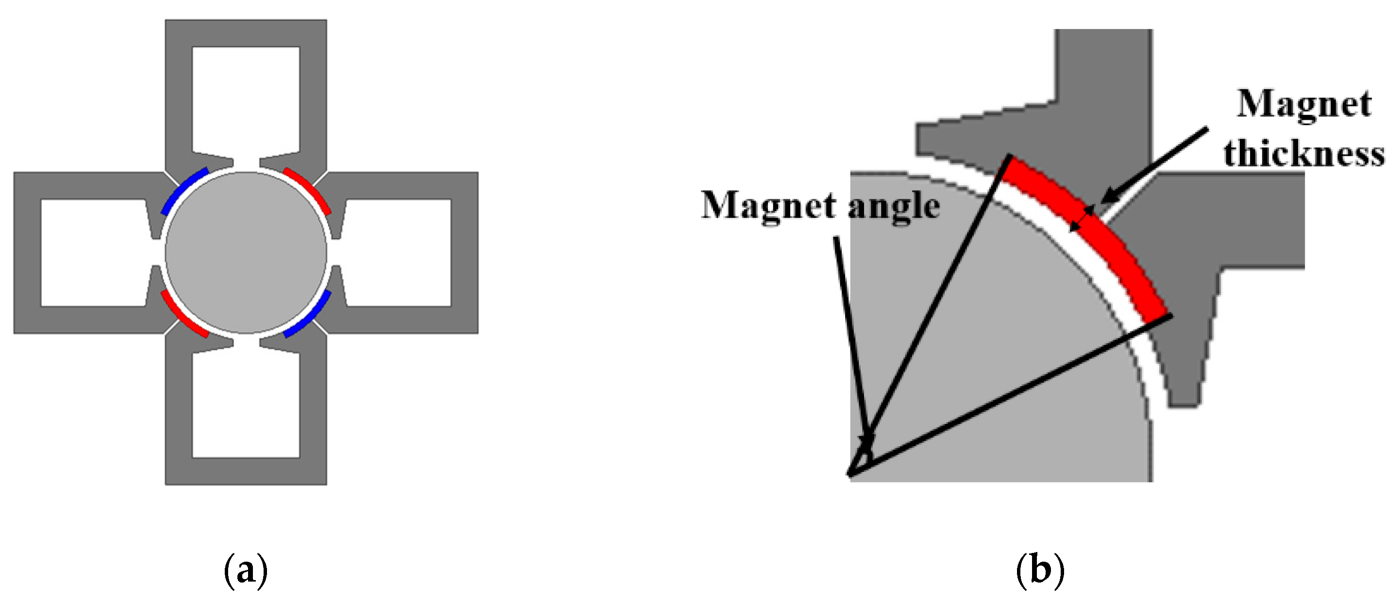
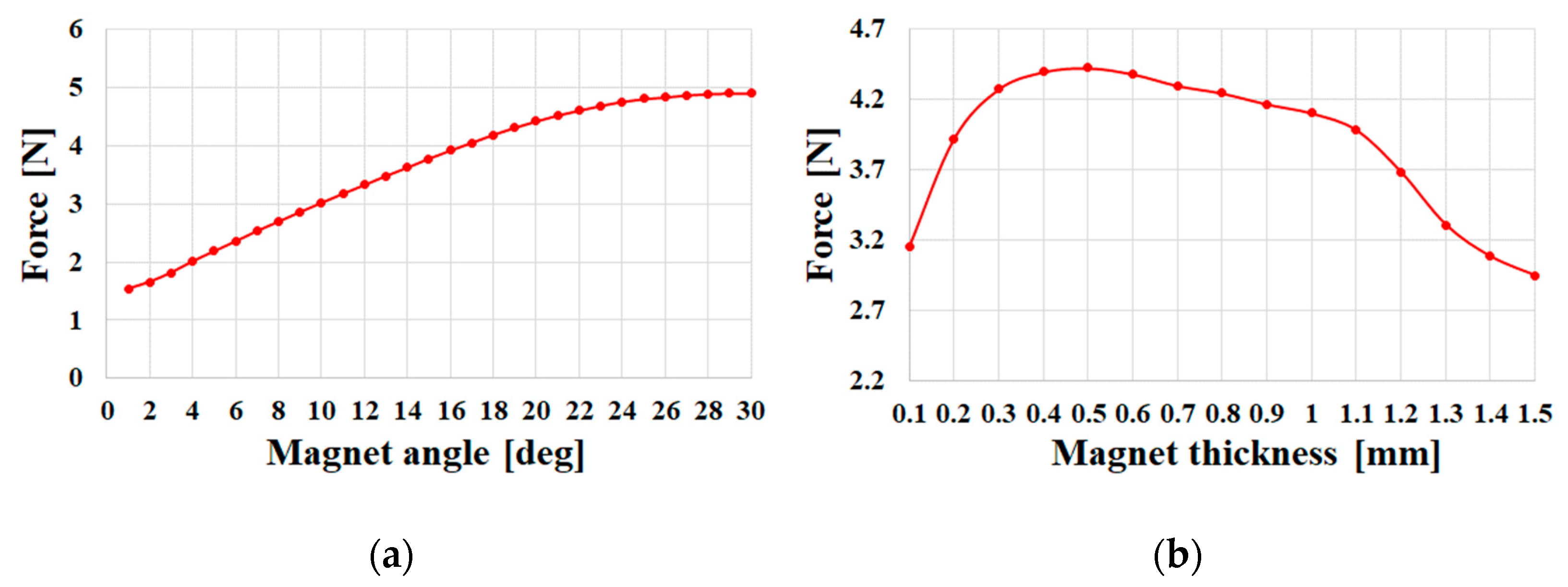
| Magnet angle | 23 | deg |
| Magnet thickness | 0.5 | mm |
| Parameter | Conventional Model | HSTMB Model | Unit |
|---|---|---|---|
| Stator diameter | 40 | 40 | mm |
| Rotor diameter | 12 | 12 | mm |
| Air gap | 0.5 | 0.5 | mm |
| Turn | 35 | 40 | - |
| 3A of current density | 10.6 | 10.6 | A/mm2 |
| 3A of force | 1.3 | 4.1 | N |
| Copper weight | 55.56 | 59.2 | g |
| Core weight | 54.22 | 36.15 | g |
| Total weight | 109.78 | 95.35 | g |
Disclaimer/Publisher’s Note: The statements, opinions and data contained in all publications are solely those of the individual author(s) and contributor(s) and not of MDPI and/or the editor(s). MDPI and/or the editor(s) disclaim responsibility for any injury to people or property resulting from any ideas, methods, instructions or products referred to in the content. |
© 2023 by the authors. Licensee MDPI, Basel, Switzerland. This article is an open access article distributed under the terms and conditions of the Creative Commons Attribution (CC BY) license (https://creativecommons.org/licenses/by/4.0/).
Share and Cite
Song, S.-W.; Kim, W.-H.; Lee, J.; Jung, D.-H. A Study on Weight Reduction and High Performance in Separated Magnetic Bearings. Energies 2023, 16, 3136. https://doi.org/10.3390/en16073136
Song S-W, Kim W-H, Lee J, Jung D-H. A Study on Weight Reduction and High Performance in Separated Magnetic Bearings. Energies. 2023; 16(7):3136. https://doi.org/10.3390/en16073136
Chicago/Turabian StyleSong, Si-Woo, Won-Ho Kim, Ju Lee, and Dong-Hoon Jung. 2023. "A Study on Weight Reduction and High Performance in Separated Magnetic Bearings" Energies 16, no. 7: 3136. https://doi.org/10.3390/en16073136