Abstract
Ammonia has been intensively studied as a clean, sustainable fuel source and an efficient energy storage medium due to its effectiveness as a hydrogen carrier molecule. However, the currently used Haber–Bosch process requires a large fossil fuel input, high temperatures and pressures, as well as a significant capital investment. These constraints prevent decentralized and small-scale ammonia production at the level of small farms and local communities. Non-thermal plasma (NTP) can promote ammonia synthesis in operating conditions in which, in a conventional process, a catalyst is generally not active. In this study, the production of NTP-assisted catalytic ammonia at milder temperatures and ambient pressure was investigated. Four different structured catalysts were prepared and tested using an experimental plant based on a dielectric barrier discharge (DBD) reactor. The effect of the gas hourly space velocity (GHSV) was investigated, as well as the effect of the N2/H2 ratio on catalyst performance. The results evidenced that the best catalytic activity (about 4 mmol h−1 of produced NH3) was obtained using the 10Ni/zeolite 13X sample with the lowest energy consumption, thus highlighting the feasibility of this innovative technology in this field.
1. Introduction
Ammonia is one of the most important products in industrial chemistry. The most well-known applications of ammonia include fertilizer, explosives, and pesticides. In recent years, innovative applications of ammonia have been intensively studied, including refrigeration, fermentation, and energy carrier potential [1]. In terms of energy content, ammonia has a heat of combustion of around 22 MJ kg−1 and a low heating value comparable to diesel fuels [2]. Most importantly, the complete combustion of ammonia is a sustainable process that does not emit any greenhouse gases. Since the first half of the 20th century, the synthesis of ammonia was publicly recognized due to the efforts of Fritz Haber and Carl Bosch, two Nobel Prize recipients, who developed and industrialized the Haber–Bosch process for ammonia production (Figure 1) [3].
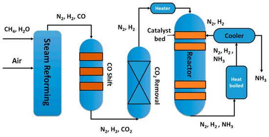
Figure 1.
Flow scheme of the Haber–Bosch process [3].
The Haber–Bosch process, in which an exothermic equilibrium reaction (1) occurs between N2 and H2, is responsible for providing over 130 million tons of ammonia annually to support approximately 40% of the world’s population. However, it is also responsible for up to 2% of global energy consumption [4].
N2 + 3H2 = 2NH3 ΔH°298K = −92.2 kJ mol−1
The reaction conditions of the Haber–Bosch process lie in the range of 200–400 atm and 400–600 °C. These intense temperature and pressure conditions are the main disadvantages of the Haber–Bosch process, as they prevent the possibility of lowering capital costs [5]. Additionally, the high pressure required for the traditional Haber–Bosch process is also a limiting factor in reducing the economies of scale in localized production facilities due to the high energy (and cost) requirements of compression. The Haber–Bosch process has gone through many changes and operational optimizations, which have pushed this process very close to the thermodynamic limit in terms of energy consumption, and is currently cost-effective for large-scale industrial production due to the exothermic and reversible properties of the reaction [6,7,8]. Looking at the future, the world population is rapidly growing and thus the demand for food will also grow much more. This will correspondingly increase the dependency on fertilizer use to increase food production, considering that ammonia constitutes a fundamental component of N-fertilizers [9]. The increase in ammonia use requires distributed NH3 synthesis at lower temperature and pressure, and on a smaller scale using the electricity from renewable sources [9]. Among all of the innovative alternative approaches for ammonia production studied in recent years, non-thermal plasma (NTP) generated using renewable electricity is an appealing option for small-scale and distributed catalytic ammonia production [3,10,11]. Plasma is considered as the fourth state of matter and it is generated by ionization, which takes place when enough heat is supplied to a gas. Plasmas are generally classified as high temperature (HTP) and low temperature plasmas (LTP) [3]. Non-thermal plasmas can be generated through an electric discharge in a gaseous volume and can be produced using different atmospheric pressure discharges, including pulsed corona, pulsed glow discharge, glow discharge, micro-hollow cathode discharge, dielectric barrier discharge (DBD), RF discharge, and microwave discharge [12]. If not in thermodynamic equilibrium, electrons are usually at very high temperatures, whereas ions and background gas are at room temperature [13]. NTP activates the nitrogen molecules that react with hydrogen, for example, on a heterogeneous catalyst, and the plasma stimulation can in principle bypass the kinetic bottlenecks in thermal-only catalytic transformations, enhancing the net reaction rates and conversions [14,15]. In some studies, the possibility to produce ammonia via NTP in the absence of catalysts has been reported. In particular, H2O has been used as a hydrogen source for nitrogen fixation into NH3, obtaining an NH3 selectivity higher than 95% [16].
In any case, this research is focused on the combined use of catalysts and NTP (the so-called plasma catalysis), in order to try to improve the performance of the conventional process [3]. A catalyst offers a different transition state for a chemical reaction, with a lower activation energy. The collisions between reactant molecules are more likely to achieve the energy required to form products than without the presence of the catalyst.
In the literature, two main categories of catalysts were employed in NTP-assisted ammonia production: Ru- and Ni-based catalysts. The former class was the most studied for NTP-assisted NH3 synthesis, and a DBD reactor was used in all the studies. Ru was deposited on different supports, including mesoporous Si–MCM-41, MgO, multi-walled carbon nanotube, and γAl2O3 [17,18,19,20,21]. All these studies showed that, apart from the metal loading (which is lower than 10 wt%), the operating conditions in terms of applied voltage, gas flow rate, and N2:H2 feed ratio influenced the catalyst performance. The addition of a promoter (mainly Mg, K, Cs, and Ba) resulted in enhanced NTP-assisted ammonia synthesis [18,19]. Kim et al. [20] extensively studied the synergistic effect between the catalyst and the NTP. In particular, the apparent activation energy for plasma-enhanced catalytic ammonia synthesis calculated from the experimental tests was in the range of 20–40 kJ mol−1, lower than the typical values of thermal-catalytic ammonia synthesis (60–115 kJ mol−1). In the authors’ opinion, these results confirmed the hypothesis that the plasma-induced vibrational excitations of N2 increased the NH3 synthesis, without affecting the hydrogenation steps in the NHx species, as well as ammonia desorption.
As mentioned above, the second class of catalysts studied in the case of the NTP-assisted NH3 synthesis were the Ni-based catalysts. In the literature, Ni metal as well as Ni deposited (loading ≥ 10 wt%) on different supports (MOF, microporous silica, γAl2O3) were investigated [22,23,24]. The studies revealed how better performances were obtained when Ni was supported on a carrier, since the resulting porous structure of the catalyst had positive effects on the limitation of (i) mass transfer limitations during the reaction, and (ii) surface hydrogen recombination. Moreover, the smaller the Ni nanoparticles, the higher the catalytic performance [24].
In the literature, different active species forming Ru and Ni were also tested for ammonia synthesis using the NTP technology, including functionalized-nanodiamond and diamond-like-carbon coatings on α-Al2O3 spheres [25], zeolite 5A [26], M/Al2O3 (M = Fe, Ni, Cu) catalysts [27,28], wool-like metal electrodes [29], and γAl2O3 pellets [30]. For example, Patil et al. [31] investigated 16 different transition metal and oxide catalysts supported on γAl2O3 in a DBD reactor. The most efficient catalysts were found to be 2 wt% Rh/Al2O3 among the platinum-group metals and 10 wt% Ni/γAl2O3 among the transitional metals. With the 2 wt% Rh catalyst, 1.43 vol% ammonia was produced with an energy efficiency of 0.94 g kWh−1.
As mentioned above, in NTP-assisted NH3 synthesis the process parameters (including applied voltage, gas flow rate, reactor wall materials, interelectrode distance, and N2:H2 feed ratio) may also influence the catalyst performance. Therefore, some studies are presently aiming at investigating the role of these parameters [32,33,34,35,36]. In particular, De Castro et al. [32] showed that when aluminum was used as a wall material, the conversion in NH3 occurred at 350 °C in 100% of the cracked N2. Gómez-Ramírez et al. [33] reported that a higher conversion was obtained with a feed ratio of N2:H2 = 1:3 with a residence time of 60 s, at a frequency of 5 kHz when using a PZT (lead zirconate titanate) ferroelectric packed-bed dielectric barrier discharge reactor (DBD). The same authors in a recent paper [34] evidenced the occurrence of inefficient intermediate reaction mechanisms that limited efficiency and showed that the rate-limiting step in ammonia synthesis and decomposition reactions were the formation of NH* species in the plasma phase and the electron impact dissociation of the molecule, respectively.
In a recent paper, van’t Veer et al. [36] investigated the role of microdischarges and their afterglows during ammonia synthesis in a DBD packed-bed reactor (with beads of Al2O3) through properly developed kinetic models. The authors concluded that the electron impact dissociation of N2 in the gas phase followed by the adsorption of the N atoms was identified as a rate-limiting step, instead of the dissociative adsorption of N2 on the catalyst surface.
Regarding the use of a reactor configuration alternative to DBD, a catalytic multireaction-zone reactor (M–RZR) system, divided in two main zones (RZ-1 for NH3 synthesis, and RZ-2 for NH3 absorption) [37] and a system composed of three reactors for the co-production of hydrogen and ammonia, using liquid metal gallium and a plasma reactor [38], has been proposed.
Fan et al. [39] investigated how the use of either N2 or air might affect NH3 synthesis from the plasma–catalytic decomposition of urea, using an Al2O3-packed DBD reactor. The results of the experimental tests showed that when air was used as a carrier gas, urea decomposition was enhanced, but the NH3 selectivity was negatively affected if compared to the use of N2. However, the use of air resulted in a decreased energy consumption and increased energy efficiency, if compared with pure N2. Moreover, the authors also reported an influence of the carrier gas composition. In fact, in the case of N2, small amounts of N2O were detected, while in the case of air, N2O and NO2 were detected in the gas phase and NH4NO3 was deposited as a solid. The authors also performed comparative tests with and without a catalyst, and the results showed that by keeping the SEI constant, higher NH3 production rates were obtained in the case of the catalytic reactor, demonstrating the synergy between the plasma and the catalyst.
The literature survey reported above highlighted that the NTP technology could be beneficial to the ammonia industry, through its potential to promote localized and environmentally friendly energy production and storage [40]. The opportunities of the non-thermal plasma technology lie with providing an avenue towards a cleaner ammonia industry, including a renewable pathway that incorporates this technology with other renewable energy approaches.
In this study, the synthesis of NTP-assisted ammonia at milder temperatures and ambient pressure was investigated. We also aimed to obtain NH3 production with lower energy consumption than that reported in literature. Four different structured catalysts, characterized by two different carriers, were prepared and tested using an experimental plant based on a dielectric barrier discharge (DBD) reactor. The effect of the gas hourly space velocity (GHSV) was investigated, as well as the effect of the N2/H2 ratio on catalyst performance. The results evidenced that the best catalytic activity (about 4 mmol h−1 of produced NH3) was obtained using the 10Ni/zeolite 13X sample with a lower energy consumption than that reported in the literature, thus highlighting the feasibility of this innovative technology in this field.
2. Materials and Methods
Four different structured catalysts were prepared, characterized, and tested in NTP-assisted ammonia synthesis, as below described.
2.1. Catalysts Preparation
The carriers used for the preparation of the catalysts were zeolite 13X and γAl2O3, both in spheres with an average diameter of 2 mm (Figure 2). The 13X zeolites used in this work had a Si/Al ratio of 1.23, corresponding to a dehydrated composition of Na86Al86Si106O384 with a lattice parameter of 2.5028 nm and angles of 90°; moreover, these zeolites contained Fe as binder. The catalysts were prepared using the wet impregnation method of the carriers in the solutions of the precursors. First, two solutions of nickel acetylacetonate (C10H14NiO4, purity 95%, Sigma-Aldrich, Burlington, MA, USA) and ruthenium acetylacetonate (C15H21RuO6, purity 97%, Sigma-Aldrich) were prepared using Acetic Acid as solvent, respectively. The two solutions were prepared with a molar ratio 1.67:1 for Ni-based catalysts and 4.2:1 for Ru-based catalysts. After each impregnation step (15 min), the catalysts were dried at 80 °C overnight, and then at 150 °C for 2 h in a muffle oven with a slope of 5 °C/min. Subsequently, the γAl2O3-supported catalysts were calcined at 600 °C in a muffle oven for 1 h with a slope of 10 °C/min, while zeolite 13X-supported catalysts were calcined at 370 °C for 1 h with the same temperature slope. The lowest calcination temperature of the zeolite 13X-based catalysts was chosen in order to avoid the disruption of the carrier’s structure. After the final calcination step, the final catalysts were 0.5%wt. Ru-Zeolite13X, 0.5%wt. Ru-γAl2O3, 10%wt. Ni-Zeolite13X, and 10%wt. Ni-γAl2O3 catalysts were presented as follows (Figure 2). The two different loadings of active species were chosen based on the literature study, in which it was evidenced that a lower content of Ru was necessary with respect to Ni.
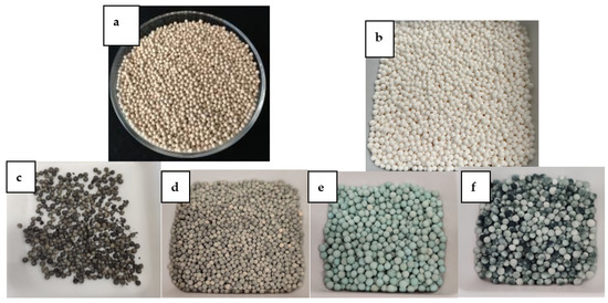
Figure 2.
(a) Zeolite 13X, (b) γAl2O3, (c) 10%wt. Ni-Zeolite13X, (d) 0.5%wt. Ru-Zeolite13X, (e) 10%wt. Ni-γAl2O3v, (f) 0.5%wt. Ru-γAl2O3.
2.2. Catalyst Characterization
The prepared catalysts were characterized by means of different physico-chemical analytical techniques. The dispersion of the active species on the carriers was investigated using a Scanning Electron Microscope (SEM) Philips Mod.XL30, coupled to an Energy Dispersive X-ray Spectrometer (EDS) Oxford. N2 physisorption was set at −196 °C using a NOVAtouch sorptometer for the determination of isotherms, specific surface areas (SSA) were calculated using the Brunauer–Emmett–Teller (BET) method, and the porosimetric features calculated using the Barrett–Joyner–Halenda (BJH) and Dubinin–Radushkevich methods for mesopores and micropores, respectively. The adherence of the washcoat to the carriers was evaluated by performing an ultrasound adherence test [41] with an ultrasonic bath, CP104 (EIA S.p.A.): the samples, immersed in a 25 mL petroleum ether containing beaker, were exposed to five cycles of 5 min, applying the 60% of rated power at 25 °C. Each ultrasonic cycle was alternated with a step of drying at 120 °C for 1 h, after which the samples were cooled, and their weight loss was evaluated.
Temperature programmed reduction (TPR) analysis was performed for (i) verifying the loading of active species for all the catalytic samples, and (ii) for reducing the catalytic samples before the reaction. For the first aim, the analysis was conducted by feeding a reducing stream to the reactor, consisting of 5% H2 in Ar with a total flowrate of 300 mL min−1 and raising the temperature from room temperature up to 600 °C with a heating rate of 10 °C min−1 for all of the samples. For the second aim, the final temperature was set to 600 °C for the γAl2O3-supported catalysts, and to 370 °C for the zeolite 13X-supported catalysts. As in the case of the calcination step, the lowest temperature of the zeolite 13X-based catalysts was chosen in order to avoid the disruption of the carrier’s internal structure.
2.3. Experimental Tests
The catalytic activity was studied in a custom designed dielectric barrier discharge (DBD) setup. The setup was comprised of four parts: the reactor core, emission spectrum capture setup, electrical characterization setup, and the mass spectrometer to follow the catalytic activity. The complete setup is shown in Figure 3.
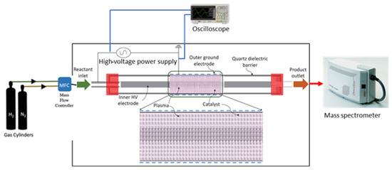
Figure 3.
Scheme of the experimental plant used for the NTP-assisted ammonia synthesis.
The reactor core comprised the reactor chamber only. To perform catalytic tests, nitrogen and hydrogen gases were connected to the reactor using mass flow controllers. The gases exiting the reactor were sent directly to the mass spectrometer (Pfeiffer Omnistar). The high-voltage power supply was connected to the reactor using Litz wire and alligator clips. The reactor was made in quartz, and it was composed of two coaxial tubes: the inner tube (0.6 cm diameter) contained the inner electrode (steel, 0.5 cm diameter) and it was placed at the center of the external tube (2.7 cm diameter) (Figure 3). The fittings were chosen to be made of PerFluoroAlkoxy (PFA) to avoid any arc formation. The outer electrode was made of steel mesh and acted as the ground electrode. The length of the plasma zone was approximately 15 cm. The impedance of the chamber was matched to deliver maximum power. The gases flowed through the annulus and two quartz frits were placed carefully such that they did not cause any pressure increase. The different catalysts were loaded to fill the plasma zone, and they were packed in the overlap area between the inner and outer electrodes. The tests were carried out under the same operating conditions: space velocity of 0.5 L/(gcat h), calculated following Equation (2), atmospheric pressure, the feed rate was N2:H2 = 1:3, and the power of the electric field was varied from 11 W to 66 W.
in which Q is the feeding volumetric flow rate. In all of the experimental tests, 20 g of catalysts were used.
Space velocity = Q/gcat
The catalyst that showed the best results was then used to test the effect of the feed rate on ammonia yield and the effect of the space velocity. The temperature was monitored using optical fiber temperature sensors (mod. TS2 by OPTOCON) specifically indicated to be insensitive to electric fields. The temperature was measured for the different configurations (packed-bed reactor) and plasma-only (plug-flow reactor). The reactor was connected to an oscilloscope to obtain the current and voltage waveforms. A Yokogawa DML 3022 oscilloscope was used, along with a Tektronix P6015A high-voltage probe having a 1000X voltage reducing rating. The current was measured using a 10X current-reducing probe to obtain the waveforms. The power consumption was calculated as Specific Energy Input (SEI), which was the ratio between the power absorbed by the setup and the volumetric flowrate [22].
3. Results
3.1. Characterization of the Catalysts
The results of the ultrasound adhesion tests were reported as weight loss vs. the number of cycles. In Figure 4, the results relevant to all of the prepared catalysts are shown, as well as to the bare zeolites 13X. The results of the test relevant to the bare γAl2O3 were not reported since negligible weight loss was detected.
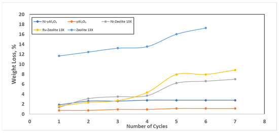
Figure 4.
Results of the ultrasound adhesion test.
The data reported in Figure 4 highlighted the fragility of the bare zeolites 13X (blue curve), which exhibited a weight loss higher than 16%. Regarding the catalytic samples, the maximum weight loss occurred after the first two cycles for all the samples. However, for the γAl2O3-based samples, no more losses were detected, while for the zeolites 13X-based samples huge weight losses were detected after the fourth cycle. This last result could mainly be due to the intrinsic fragility of the zeolite spheres, and not only to the loss of active species; in fact, starting at the fourth cycle, a comminution phenomenon was clearly visible. In any case, and even in the worst case, these results were evidence that a good adhesion of the active phase on the catalyst had been realized.
The N2 adsorption–desorption isotherms for the catalytic samples are reported in Figure 5.
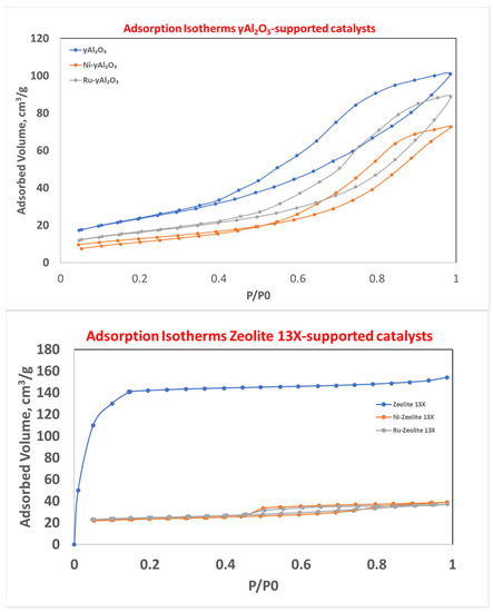
Figure 5.
N2 adsorption–desorption isotherms for γAl2O3- (top) and zeolite 13X-supported catalysts (bottom).
As can be seen from Figure 5-top, the γAl2O3-based samples showed, according to the IUPAC nomenclature, an IV-type isotherm (typical of mesoporous materials) with an H3 hysteresis. It is important to note that the catalytic samples (grey and orange curves) showed a lower height at low values of P/P0 with respect to the bare carrier (blue curve). This meant that the active species deposition resulted in a partial occlusion of the micropore present in the bare sample. The analysis in Figure 5-bottom evidenced that the bare zeolite 13X (blue curve) had an I-type isotherm (typical of microporous materials), according to the IUPAC nomenclature. After the active species deposition (grey and orange curves), it was clear that (i) the occlusion of most of the micropores, and (ii) the creation of mesopores (hysteresis did not present in the blue curve) occurred.
The mesoporous behavior could also be seen from the distribution of the pore dimensions (Figure 6).
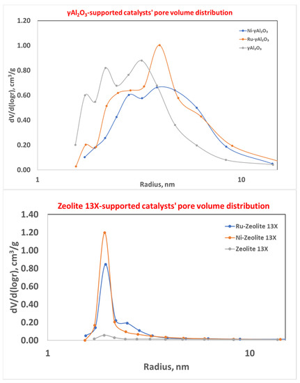
Figure 6.
Mesopore size distribution for γAl2O3- (top) and zeolite 13X-supported catalysts (bottom).
In particular, the addition of the active species on zeolite 13X resulted in an increase in the mesopores (blue and orange curves) with respect to the fresh carrier (grey curve), which was characterized by a prominent number of pores with a radius lower than 2 nm. In any case, the pore distribution was narrow, and the mean pore radius was in the range of 1.91–1.93 nm, while for γAl2O3-supported catalysts the pore dimension distribution was wider and centered at the higher values of the pore radius.
The specific surface area and the porosimetric properties of the different samples are reported in Table 1.

Table 1.
Properties of the different catalytic samples.
The data reported in Table 1 showed that the active species deposition on the supports resulted in (i) the decrease in the specific surface area (the higher the metal loading, the higher the decrease), and (ii) the decrease in the micropores volume. Regarding the mesopores volume, an inverse trend was evident: the zeolite 13X-based catalysts showed an increase, while alumina-based catalysts showed a decrease, due to the initial characteristics of the supports. In fact, zeolite13X are mainly microporous materials, as evident from the isotherm, and after the Ni and Ru deposition, mesopores are created. By further analyzing Table 1, the active species deposition resulted in the occlusion of the pores with lower width, which consequently lost their “micropore” behavior and caused the increase in the pore width in the “mesopore” region. In any case, the SSA value of the final catalytic samples was higher than 100 m2/g.
The SEM-EDX images are shown in Figure 7 for all the catalytic samples. It was clearly seen that both nickel and ruthenium were homogeneously spread throughout the catalysts’ surfaces both on zeolite 13X and γ-Al2O3.
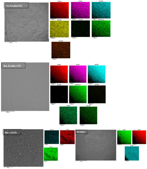
Figure 7.
SEM-EDX images of the different catalytic samples.
The temperature programmed reduction results are shown in Figure 8.
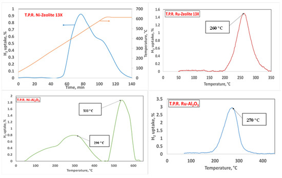
Figure 8.
TPR results for the different catalytic samples. Operating conditions: 95% Ar and 5% H2.
All of the catalytic samples showed reduction peaks consistent with those found in the literature [42,43,44]. In particular, Ru(III) usually showed a single peak centered in the range of 250–280 °C, if deposited either on γAl2O3 [42] or on zeolite 13X [43]. In the case of Ni(II), two peaks were reported in the range of 300–550 °C when γAl2O3 [44] and zeolite 13X [45] were used as supports. Our catalytic samples showed the reduction peaks reported in Table 2.
Table 2.
Reduction peaks, experimental, and theoretical H2 consumption for the prepared catalysts as results of the H2-TPR.
The comparison of the experimentally consumed H2 and the theoretical H2 might allow for the verification of the loading of metal on the final catalysts. The former was calculated as the area under the peaks of the figures reported above, while the latter was calculated following Equations (3) and (4) for Ru and Ni, starting with the assumed loading of the two metals.
Ru2O3 + 3H2 = 2Ru + 3 H2O
NiO + H2 = Ni + H2O
In Table 2, the experimental and theoretical H2 consumptions are reported.
As evident from the data reported above, the experimental and theoretical H2 consumptions are in good agreement, thus confirming that the final catalysts contained the desired loading of metals.
3.2. Experimental Tests
The results of the experimental tests for the four catalysts are shown in Figure 9, as the NH3 produced in the gases exiting the catalytic bed (in %vol) vs. temperature.
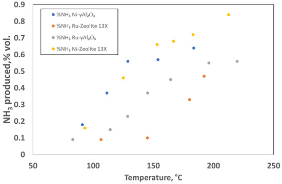
Figure 9.
Results of the NTP-assisted catalytic activity tests. Operating conditions: space velocity of 0.5 L (gcat h)−1 and atmospheric pressure, feed rate N2:H2 = 1:3 and the power of the electric field was varied from 11 W to 66 W.
The results shown in Figure 9 evidenced that it was possible to produce ammonia at an atmospheric pressure and relatively low temperature. In particular, both of the Ni-loaded catalysts had a good ammonia yield even at lower temperatures (and consequently at lower energy inputs). The best result shown in this set of tests was 0.84%vol. ammonia at a temperature of 212.5 °C (66 W) and it was obtained with the Ni-Zeolite 13X catalyst. The NH3 synthesis using the hybrid plasma–catalytic process had intrinsic challenges, such as the plasma-induced reverse reaction (NH3 decomposition) [36] and the complexity of plasma−catalyst interactions. In the hybrid system, the desorbed ammonia from the catalyst surface could be easily decomposed in the plasma discharge via electron impact dissociation [46], which limited the practical ammonia yield that could be achieved as well as the energy yield for ammonia production. The use of supported metal catalysts on the mesoporous materials (such as zeolite 13X, after active species deposition, and γAl2O3 used in this work) might be beneficial for avoiding the NH3 decomposition: the gradient of NH3 concentration across the mesoporous framework enabled the formed NH3 to diffuse into the mesopores, thus limiting the plasma-induced reverse reaction (NH3 decomposition) due to the absence of plasma discharge in the mesopores [47]. The higher content of Ni deposited on the external surface of the supports made it more accessible than Ru, thus explaining the better performance of the Ni-based catalysts. In any case, the very interesting result obtained in this study using the 10Ni/zeolite 13X catalyst needs to be further investigated for a better understanding of the underlying phenomena. In fact, in this catalyst, partially oxidized Ni was still present (the preliminary reduction in the catalyst was performed at 370 °C, as previously mentioned).
Due to the higher NH3 %vol present in the gases exiting the catalytic bed, this catalyst was chosen to test the feed ratio effect on the ammonia yield. The feed compositions tested were H2:N2 4:1, 3:1, 2:1, 1:1, 1:2, 1:3, and a volumetric flowrate of 180 Ncm3 min−1. The results of these tests are shown in Figure 10. These tests showed yet again an increase in ammonia yield with temperature. The best results were obtained with the stoichiometric ratio of H2:N2 = 3:1. This was consistent with some studies reported in the literature [48], and it was related to a more frequent attachment of the hydrogen radicals on the catalyst surface, which favored the ammonia production.
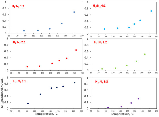
Figure 10.
Effect of the feed ratio on the catalytic activity of the Ni-Zeolite 13X catalyst, 0.5 L (gcat h)−1. In the figure, the produced NH3 (vol%) is reported vs. T.
To better understand the effect of the feed ratio, a test at a fixed power of 44 W (about 180 °C) was performed for each feed ratio, and the results are shown in Figure 11.
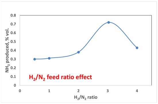
Figure 11.
Feed ratio effect at the same operating conditions for the Ni-Zeolite 13X catalyst, 0.5 L (gcat h)−1, P = 66 W.
The results reported above again evidenced that as soon as the operating conditions moved away from the stoichiometric conditions, there was a drastic reduction in the ammonia yield, thus confirming the previously reported data.
Finally, the space velocity effect was studied by testing the 10Ni_zeolite 13X catalyst in two different space velocity conditions, 0.5 L (gcat h)−1 and 0.25 L (gcat h)−1. The results are reported in Figure 12 as NH3 produced (mmol h−1) vs. temperature.
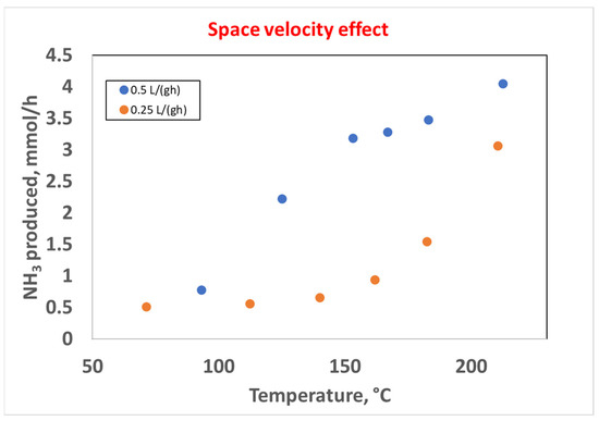
Figure 12.
Effect of the space velocity on the catalytic activity in the 10Ni_zeolite 13X catalyst, space velocities of 0.5 L (gcat h)−1 (blue curve) and 0.25 L (gcat h)−1 (orange curve), H2:N2 = 3.
The results reported above highlighted that the higher space velocity, corresponding to a higher flow rate of reactants, resulted in a higher production of NH3 in all of the investigated range of temperatures. This result was consistent with other studies in the literature in which the effect of the flow rate was investigated [31], and the higher ammonia generation efficiency could possibly be due to the thermal decomposition of ammonia at lower flow rates. About 4 mmol h−1 of NH3 were produced at 212.5 °C, with an energy input of 66 W.
Finally, the results of this work were compared with the those in the literature in terms of Specific Energy Input (SEI), and the results are reported in Table 3.
Table 3.
Ammonia production and SEI comparison in packed DBD reactors.
As can be seen from the data reported above, the best catalyst presented in this work showing the highest production of NH3 at 0.5 L (gcat−1 h−1, had an SEI of 22 kJ L−1. The comparison of this value with other Ni-based catalysts with a higher Ni loading, even if with a different support, evidenced the lowest energy consumption assured by using the proposed catalyst as reported in Table 3 [22,23,45]. The comparison with a Ni-based catalyst with the same Ni loading but again with a different support [31], evidenced practically the same SEI and an NH3 production slightly lower at the highest space velocity used in this study, even if different operating conditions were used. Moreover, the catalyst proposed in this study was a structured catalyst, different from the other catalysts present in Table 3, which were in powder form, so without the mass transfer issues present in the former. Moreover, the obtained value was far from the conventional Haber–Bosch process, but the NTP-assisted NH3 synthesis operating at milder conditions (lower temperature and ambient pressure) and requiring only a source of electricity was a promising alternative for smaller-scale decentralized production.
4. Conclusions
In this study, the NTP-assisted synthesis of ammonia at milder temperatures and ambient pressure was investigated. Four different structured catalysts, characterized by two different carriers, were prepared and tested using an experimental plant based on a dielectric barrier discharge (DBD) reactor. The effect of the gas hourly space velocity (GHSV) was investigated, as well as the effect of the N2/H2 ratio on catalyst performance. The results evidenced that the best catalytic activity (about 4 mmol h−1 of produced NH3) was obtained at 212.5 °C with a H2:N2 ratio = 3, using the 10Ni/zeolite 13X sample. This sample also showed a comparable (and in many cases higher) production of NH3 when the SEI was comparable to other catalysts in the literature, even if the latter catalysts were in powder form, and thus without the mass transfer issues present in the former. These results highlighted the feasibility of this innovative technology in this field.
The results shown in this work confirm the hypothesis that nitrogen molecules can be activated at temperatures lower than 450 °C and, most importantly, at atmospheric pressure. Considering the Haber–Bosch process’ ammonia yield per pass, it is possible to say that the plasma catalysis approach, if suitably optimized, can be a way to obtain a sustainable production of ammonia. The key to achieve this objective is the improvement in the process’ energy efficiency, which will allow adequate ammonia yields to be reached through considerably lower energy inputs.
Author Contributions
Conceptualization, E.M., L.C., M.M. and V.P.; methodology, E.M., L.C., M.M. and V.P.; software, E.M., L.C., M.M. and V.P.; validation, E.M., L.C., M.M. and V.P.; formal analysis, E.M., L.C., M.M. and V.P.; investigation, E.M., L.C., M.M. and V.P.; resources, E.M., L.C., M.M. and V.P.; data curation, E.M., L.C., M.M. and V.P.; writing—original draft preparation, E.M., L.C., M.M. and V.P.; writing—review and editing, E.M., L.C., M.M. and V.P.; visualization, E.M., L.C., M.M. and V.P.; supervision, E.M., L.C., M.M. and V.P.; project administration, E.M., L.C., M.M. and V.P. All authors have read and agreed to the published version of the manuscript.
Funding
This research received no external funding.
Data Availability Statement
Not available.
Acknowledgments
The authors are grateful to Paolo Tramonti for the SEM and SEM-EDX analysis.
Conflicts of Interest
The authors declare no conflict of interest.
References
- Akiyama, M.; Aihara, K.; Sawaguchi, T.; Matsukata, M.; Iwamoto, M. Ammonia decomposition to clean hydrogen using non-thermal atmospheric-pressure plasma. Int. J. Hydrogen Energy 2018, 43, 14493–14497. [Google Scholar] [CrossRef]
- Peng, P.; Chen, P.; Schiappacasse, C.; Zhou, N.; Anderson, E.; Chen, D.; Liu, J.; Cheng, Y.; Hatzenbeller, R.; Addy, M.; et al. A review on the non-thermal plasma-assisted ammonia synthesis technologies. J. Clean. Prod. 2018, 177, 597–609. [Google Scholar] [CrossRef]
- Palma, V.; Cortese, M.; Renda, S.; Ruocco, C.; Martino, M.; Meloni, E. A Review about the Recent Advances in Selected NonThermal Plasma Assisted Solid–Gas Phase Chemical Processes. Nanomaterials 2020, 10, 1596. [Google Scholar] [CrossRef] [PubMed]
- Vu, M.-H.; Sakar, M.; Do, T.-O. Insights into the Recent Progress and Advanced Materials for Photocatalytic Nitrogen Fixation for Ammonia (NH3) Production. Catalysts 2018, 8, 621. [Google Scholar] [CrossRef]
- Hong, J.; Prawer, S.; Murphy, A.B. Plasma Catalysis as an Alternative Route for Ammonia Production: Status, Mechanisms, and Prospects for Progress. ACS Sustain. Chem. Eng. 2018, 6, 15–31. [Google Scholar] [CrossRef]
- Carreon, M.L. Plasma catalytic ammonia synthesis: State of the art and future directions. J. Phys. D Appl. Phys. 2019, 52, 483001. [Google Scholar] [CrossRef]
- Zhou, D.; Zhou, R.; Zhou, R.; Liu, B.; Zhang, T.; Xian, Y.; Cullen, P.J.; Lu, X.; Ostrikov, K. Sustainable ammonia production by non-thermal plasmas: Status, mechanisms, and opportunities. Chem. Eng. J. 2021, 421, 129544. [Google Scholar] [CrossRef]
- Yan, P.; Guo, W.; Liang, Z.; Meng, W.; Yin, Z.; Li, S.; Li, M.; Zhang, M.; Yan, J.; Xiao, D.; et al. Highly efficient K-Fe/C catalysts derived from metal-organic frameworks towards ammonia synthesis. Nano Res. 2019, 12, 2341–2347. [Google Scholar] [CrossRef]
- Anastasopoulou, A.; Keijzer, R.; Patil, B.; Lang, J.; van Rooij, G.; Hessel, V. Environmental impact assessment of plasma-assisted and conventional ammonia synthesis routes. J. Ind. Ecol. 2020, 24, 1171–1185. [Google Scholar] [CrossRef]
- Barboun, P.M.; Hicks, J.C. Unconventional Catalytic Approaches to Ammonia Synthesis. Annu. Rev. Chem. Biomol. Eng. 2020, 11, 503–521. [Google Scholar] [CrossRef]
- Van Duc Long, N.; Al-Bared, M.; Lin, L.; Davey, K.; Tran, N.; Pourali, N.; Ostrikov, K.K.; Rebrov, E. Hessel Understanding plasma-assisted ammonia synthesis via crossing discipline borders of literature: A critical review. Chem. Eng. Sci. 2022, 263, 118097. [Google Scholar] [CrossRef]
- Patil, B.S.; Wang, Q.; Hessel, V.; Lang, J. Plasma N2-fixation: 1900–2014. Catal. Today 2015, 256, 49–66. [Google Scholar] [CrossRef]
- Kim, H.-H.; Teramoto, Y.; Ogata, A.; Takagi, H.; Nanba, T. Plasma Catalysis for Environmental Treatment and Energy Applications. Plasma Chem. Plasma Process. 2016, 36, 45–72. [Google Scholar] [CrossRef]
- Bogaerts, A.; Neyts, E.C. Plasma Technology: An Emerging Technology for Energy Storage. ACS Energy Lett. 2018, 3, 1013–1027. [Google Scholar] [CrossRef]
- Mehta, P.; Barboun, P.M.; Engelmann, Y.; Go, D.B.; Bogaerts, A.; Schneider, W.F.; Hicks, J.C. Plasma-Catalytic Ammonia Synthesis beyond the Equilibrium Limit. ACS Catal. 2020, 10, 6726–6734. [Google Scholar] [CrossRef]
- Gorbanev, Y.; Vervloessem, E.; Nikiforov, A.; Bogaerts, A. Nitrogen Fixation with Water Vapor by Nonequilibrium Plasma: Toward Sustainable Ammonia Production. ACS Sustain. Chem. Eng. 2020, 8, 2996–3004. [Google Scholar] [CrossRef]
- Peng, P.; Cheng, Y.; Hatzenbeller, R.; Addy, M.; Zhou, N.; Schiappacasse, C.; Chen, D.; Zhang, Y.; Anderson, E.; Liu, Y.; et al. Ru-based multifunctional mesoporous catalyst for low-pressure and non-thermal plasma synthesis of ammonia. Int. J. Hydrogen Energy 2017, 42, 19056–19066. [Google Scholar] [CrossRef]
- Peng, P.; Li, Y.; Cheng, Y.; Deng, S.; Chen, P.; Ruan, R. Atmospheric Pressure Ammonia Synthesis Using Non-thermal Plasma Assisted Catalysis. Plasma Chem. Plasma Process. 2016, 36, 1201–1210. [Google Scholar] [CrossRef]
- Kim, H.-H.; Teramoto, Y.; Ogata, A.; Takagi, H.; Nanba, T. Atmospheric-pressure nonthermal plasma synthesis of ammonia over ruthenium catalysts. Plasma Process. Polym. 2017, 14, 1600157. [Google Scholar] [CrossRef]
- Rouwenhorst, K.H.R.; Kim, H.-H.; Lefferts, L. Vibrationally Excited Activation of N2 in Plasma-Enhanced Catalytic Ammonia Synthesis: A Kinetic Analysis. ACS Sustain. Chem. Eng. 2019, 7, 17515–17522. [Google Scholar] [CrossRef]
- Xie, Q.; Zhuge, S.; Song, X.; Lu, M.; Yu, F.; Ruan, R.; Nie, Y. Non-thermal atmospheric plasma synthesis of ammonia in a DBD reactor packed with various catalysts. J. Phys. D Appl. Phys. 2020, 53, 064002. [Google Scholar] [CrossRef]
- Shah, J.; Wu, T.; Lucero, J.; Carreon, M.A.; Carreon, M.L. Nonthermal Plasma Synthesis of Ammonia over Ni-MOF-74. ACS Sustain. Chem. Eng. 2019, 7, 377–383. [Google Scholar] [CrossRef]
- Akay, G.; Zhang, K. Process Intensification in Ammonia Synthesis Using Novel Coassembled Supported Microporous Catalysts Promoted by Nonthermal Plasma. Ind. Eng. Chem. Res. 2017, 56, 457–468. [Google Scholar] [CrossRef]
- Gorky, F.; Best, A.; Jasinski, J.; Allen, B.J.; Alba-Rubio, A.C.; Carreon, M.L. Plasma catalytic ammonia synthesis on Ni nanoparticles: The size effect. J. Catal. 2021, 393, 369–380. [Google Scholar] [CrossRef]
- Hong, J.; Aramesh, M.; Shimoni, O.; Seo, D.H.; Yick, S.; Greig, A.; Charles, C.; Prawer, S.; Murphy, A.B. Plasma Catalytic Synthesis of Ammonia Using Functionalized-Carbon Coatings in an Atmospheric-Pressure Non-equilibrium Discharge. Plasma Chem. Plasma Process. 2016, 36, 917–940. [Google Scholar] [CrossRef]
- Shah, J.R.; Gorky, F.; Lucero, J.; Carreon, M.A.; Carreon, M.L. Ammonia Synthesis via Atmospheric Plasma Catalysis: Zeolite 5A, a Case of Study. Ind. Eng. Chem. Res. 2020, 59, 5167–5176. [Google Scholar] [CrossRef]
- Wang, Y.; Craven, M.; Yu, X.; Ding, J.; Bryant, P.; Huang, J.; Tu, X. Plasma-Enhanced Catalytic Synthesis of Ammonia over a Ni/Al2O3 Catalyst at Near-Room Temperature: Insights into the Importance of the Catalyst Surface on the Reaction Mechanism. ACS Catal. 2019, 9, 10780–10793. [Google Scholar] [CrossRef]
- Herrera, F.A.; Brown, G.H.; Barboun, P.; Turan, N.; Mehta, P.; Schneider, W.F.; Hicks, J.C.; Go, D.B. The impact of transition metal catalysts on macroscopic dielectric barrier discharge (DBD) characteristics in an ammonia synthesis plasma catalysis reactor. J. Phys. D Appl. Phys. 2019, 52, 224002. [Google Scholar] [CrossRef]
- Iwamoto, M.; Akiyama, M.; Aihara, K.; Deguchi, T. Ammonia Synthesis on Wool-Like Au, Pt, Pd, Ag, or Cu Electrode Catalysts in Nonthermal Atmospheric-Pressure Plasma of N2 and H2. ACS Catal. 2017, 7, 6924–6929. [Google Scholar] [CrossRef]
- Zhu, X.; Hu, X.; Wu, X.; Cai, Y.; Zhang, H.; Tu, X. Ammonia synthesis over γ-Al2O3 pellets in a packed-bed dielectric barrier discharge reactor. J. Phys. D Appl. Phys. 2020, 53, 164002. [Google Scholar] [CrossRef]
- Patil, B.S.; Cherkasov, N.; Srinath, N.V.; Lang, J.; Ibhadon, A.O.; Wang, Q.; Hessel, V. The role of heterogeneous catalysts in the plasma-catalytic ammonia synthesis. Catal. Today 2021, 362, 2–10. [Google Scholar] [CrossRef]
- De Castro, A.; Alegre, D.; Tabarés, F.L. Ammonia formation in N2/H2 plasmas on ITER-relevant plasma facing materials: Surface temperature and N2 plasma content effects. J. Nucl. Mater. 2015, 463, 676–679. [Google Scholar] [CrossRef]
- Gómez-Ramírez, A.; Montoro-Damas, A.M.; Cotrino, J.; Lambert, R.M.; González-Elipe, A.R. About the enhancement of chemical yield during the atmospheric plasma synthesis of ammonia in a ferroelectric packed bed reactor. Plasma Process. Polym. 2016, 14, 1600081. [Google Scholar] [CrossRef]
- Navascués, P.; Obrero-Pérez, J.M.; Cotrino, J.; González-Elipe, A.R.; Gómez-Ramírez, A. Unraveling Discharge and Surface Mechanisms in Plasma-Assisted Ammonia Reactions. ACS Sustain. Chem. Eng. 2020, 8, 14855–14866. [Google Scholar] [CrossRef]
- Barboun, P.; Mehta, P.; Herrera, F.A.; Go, D.B.; Schneider, W.F.; Hicks, J.C. Distinguishing Plasma Contributions to Catalyst Performance in Plasma-Assisted Ammonia Synthesis. ACS Sustain. Chem. Eng. 2019, 7, 8621–8630. [Google Scholar] [CrossRef]
- Van‘t Veer, K.; Engelmann, Y.; Reniers, F.; Bogaerts, A. Plasma-Catalytic Ammonia Synthesis in a DBD Plasma: Role of Microdischarges and Their Afterglows. J. Phys. Chem. C 2020, 124, 22871–22883. [Google Scholar] [CrossRef]
- Akay, G. Sustainable Ammonia and Advanced Symbiotic Fertilizer Production Using Catalytic Multi-Reaction-Zone Reactors with Nonthermal Plasma and Simultaneous Reactive Separation. ACS Sustain. Chem. Eng. 2017, 5, 11588–11606. [Google Scholar] [CrossRef]
- Sarafraz, M.M.; Tran, N.N.; Pourali, N.; Rebrov, E.V.; Hessel, V. Thermodynamic potential of a novel plasma-assisted sustainable process for co-production of ammonia and hydrogen with liquid metals. Energy Convers. Manag. 2020, 210, 112709. [Google Scholar] [CrossRef]
- Fan, X.; Li, J.; Qiu, D.; Zhu, T. Production of ammonia from plasma-catalytic decomposition of urea: Effects of carrier gas composition. J. Environ. Sci. 2018, 66, 94–103. [Google Scholar] [CrossRef]
- Li, S.; Medrano, J.A.; Hessel, V.; Gallucci, F. Recent Progress of Plasma-Assisted Nitrogen Fixation Research: A Review. Processes 2018, 6, 248. [Google Scholar] [CrossRef]
- Meloni, E.; Martino, M.; Palma, V. Microwave assisted steam reforming in a high efficiency catalytic reactor. Renew. Energy 2022, 197, 893–901. [Google Scholar] [CrossRef]
- Betancourt, P.; Rives, A.; Hubaut, R.; Scott, C.; Goldwasser, J. A study of the Ruthenium-Alumina System. Appl. Catal. A Gen. 1998, 170, 307–314. [Google Scholar] [CrossRef]
- Bond, G.C.; Garcia, J. Hydrogenolysis of alkenes: Reaction of η-butane on Ru/Zeolite catalysts. Catal. Sci. Technol. 2017, 7, 5294–5300. [Google Scholar] [CrossRef]
- Sadannandam, G.; Ramya, K.; Kishore, D.; Durgakymari, V.; Subrahmanyam, M.; Chary, K. A study to initiate development of sustainable Ni/͏γ-Al2O3 catalysts for hydrogen production from steam reforming or biomass-derived glycerol. RCS Adv. 2014, 4, 32429–32437. [Google Scholar] [CrossRef]
- Wei, L.; Haije, W.; Kumar, N.; Peltonen, J.; Peurla, M.; Grenman, H.; De Jong, W. Influence of Nickel Precursors on the properties and performance of Ni impregnated Zeolite 5A and 13X catalysts in CO2 methanation. Catal. Today 2021, 362, 35–46. [Google Scholar] [CrossRef]
- Kevin, H.R.; Mani, R.S.; Lefferts, L. Improving the Energy Yield of Plasma-Based Ammonia Synthesis with In Situ Adsorption. ACS Sustain. Chem. Eng. 2022, 10, 1994–2000. [Google Scholar] [CrossRef]
- Wang, Y.; Yang, W.; Xu, S.; Zhao, S.; Chen, G.; Weidenkaff, A.; Hardacre, C.; Fan, X.; Huang, J.; Tu, X. Shielding Protection by Mesoporous Catalysts for Improving Plasma-Catalytic Ambient Ammonia Synthesis. J. Am. Chem. Soc. 2022, 144, 12020–12031. [Google Scholar] [CrossRef]
- Gorky, F.; Guthrie, S.R.; Smoljan, C.S.; Crawford, J.M.; Carreon, M.A.; Carreon, M.L. Plasma ammonia synthesis over mesoporous silica SBA-15. J. Phys. D Appl. Phys. 2021, 54, 264003. [Google Scholar] [CrossRef]
Disclaimer/Publisher’s Note: The statements, opinions and data contained in all publications are solely those of the individual author(s) and contributor(s) and not of MDPI and/or the editor(s). MDPI and/or the editor(s) disclaim responsibility for any injury to people or property resulting from any ideas, methods, instructions or products referred to in the content. |
© 2023 by the authors. Licensee MDPI, Basel, Switzerland. This article is an open access article distributed under the terms and conditions of the Creative Commons Attribution (CC BY) license (https://creativecommons.org/licenses/by/4.0/).