Article

Performance Assessment of the Heat Recovery System of a 12 MW SOFC-Based Generator on Board a Cruise Ship through a 0D Model

1
Industrial Engineering Department, University of Naples Federico II, 80125 Napoli, Italy
2
Fincantieri Group S.p.a., 34123 Trieste, Italy
*
Author to whom correspondence should be addressed.
Energies 2023, 16(8), 3334; https://doi.org/10.3390/en16083334
Submission received: 16 February 2023 / Revised: 26 March 2023 / Accepted: 6 April 2023 / Published: 9 April 2023

Abstract

:
The present work considers a 12 MW Solid Oxide Fuel Cell (SOFC) power plant integrated with a heat recovery system installed on board an LNG-fuelled cruise ship of about 175,000 gross tonnes and 345 m in length. The SOFC plant is fed by LNG and generates electrical power within an integrated power system configuration; additionally, it provides part of the thermal energy demand. A zero-dimensional (0D) Aspen Plus model has been built-up to simulate the SOFC power plant and to assess the performances of the proposed heat recovery system. The model has been validated by comparing the results obtained with data from the literature and commercial SOFC modules. The integrated system has been optimized in order to maximize steam production since it is the most requested thermal source on board. The main design outcome is that the steam produced is made by the recovered water from the SOFC exhaust by about 50–60%, thus reducing the onboard water storage or production. Additionally, results indicate that such an integrated system could save up to about 14.4% of LNG.

1. Introduction

It is well-known that shipping must increase energy efficiency and significantly reduce the environmental impact to comply with more and more stringent regulations [1,2]. However, it seems that traditional diesel engines and bunker fuels cannot meet these requests; consequently, ship owners need to adopt alternative technological solutions [3,4,5,6].
In the last decades, there have been investigating of several technologies to be implemented on board ships, which include both engine improvements, such as advanced fuel injection systems, exhaust gas recirculation, and innovative turbochargers [7,8], and using alternative technologies, such as batteries and Fuel Cells (FCs) [9,10,11,12]. Exhaust gas after-treatments, such as scrubbers or selective catalytic reduction, have been considered as well [13]. Finally, using different bunker fuels, which include both fossil ones, such as low sulfur diesel or liquefied natural gas (LNG), and innovative ones that could be produced from renewable sources, such as green hydrogen and methanol, could contribute to reducing the emission from shipping. A combination of innovative technologies and alternative fuel sources is likely forecasted to be implemented on board ships to reach the zero-emission ship goal as soon as possible [14,15,16,17].
Considering the overall benefits that could come from all the above-mentioned technologies, it seems that FCs have the greatest potential to be implemented on board ships.
FCs are electrochemical devices that convert the chemical energy of a fuel and an oxidant directly to electricity without any combustion. As a result, FC can reach higher efficiencies than typical engines or gas turbines; additionally, the electrochemical conversion occurs without emitting relevant harmful compounds. Further FC advantages are silent operation, modularity, and low maintenance, resulting in overall cost reductions. The major disadvantages are the current low-experience level and high CAPEX compared to ICEs.
FCs were invented more than 100 years ago and have been used for decades in the aerospace and military sectors. Over the past decades, they have been spreading for commercial use within areas such as off-grid power supply, backup power, and land-based transportation as well [18,19,20,21]. For maritime use, only a few demonstration projects have been carried out also due to a regulation lacking [11,22,23]. Nevertheless, FC technology is becoming more and more relevant following the implementation of new fuels [22,24].
There are different FC types depending on the electrolyte’s material and the fuelling, each one with its advantages and drawbacks. For maritime use, the most relevant are the Proton Exchange Membrane FC (PEM) and the Solid Oxide FC (SOFC). A PEM operates typically at about 80 °C, while SOFC operates in the range of 500–1000 °C [11,25].
The basic configuration of SOFC consists of two electrodes (anode and cathode) separated by an electrolyte generally made of ceramics or cermets. Components’ materials change based on the operating temperature; as a consequence, SOFCs can be categorized as high-temperature SOFCs (HT-SOFCs), working within the range of 800–1000 °C, intermediate-temperature SOFCs (IT-SOFCs) in the range of 500–800 °C, and low-temperature SOFC (LT-SOFCs) in the range of 100–500 °C. For instance, the most commonly used electrolyte material is made of yttria-stabilized zirconia (YSZ), mostly for HT-SOFC, other materials have also been investigated for lower temperatures SOFC applications, such as scandia-stabilized zirconia (ScSZ) and gadolinium doped ceria (GDC) [26,27,28]. Anode material is generally a composite made of a mixture of NiO and YSZ powders, which under reducing conditions, form a Ni-YSZ cermet [29,30]. Lanthanum strontium manganite (LSM) is the most used cathode material for HT-SOFCs, but other materials are requested for lower operating temperatures [31,32]. Additionally, metallic interconnects such as platinum are required for electron conduction and connecting each unit cell.
A PEM is more compact, lightweight, and can easily handle transients and on-off cycles than HT-FCs, but it must be powered only by high-purity hydrogen. On the other hand, a SOFC has the potential for higher efficiency due to lower electrical resistance in the cells and since it produces high-value heat that can be utilized on board (in cogeneration configuration); moreover, it can operate on multiple fuels such as LNG, Liquefied Petroleum Gas (LPG), methanol, ammonia, hydrogen, and Liquid Organic Hydrogen Carriers (LOHC) [27,33,34,35].
However, the choice of the most suitable FC type to be implemented on board ships will depend strongly on the vessel type, operational profile, and route of the specific use case. For instance, in the case of SOFC, it is more attractive for larger vessels operating over larger distances between each refueling, such as deep-sea vessels, tankers, container ships, and cruise vessels [23,36,37]. These applications require fuels with high energy density, where efficiency is essential to minimize fuel consumption, cost, and required tank capacity [38].
The energy crisis and the soaring fuel oil price have pushed for the introduction of technologies able to convert the waste heat from internal combustion engines (ICEs) into useful energy to improve the efficiency of fuel consumption. The reduction in fuel consumption will directly increase the cruising range as well. Furthermore, capturing and reusing the waste heat onboard is an emission-free method to reduce the overall ship’s environmental impact. As the flow rate of waste heat sources onboard ships is large, the potential for waste heat recovery is particularly promising [39,40].
In any heat recovery situation, it is essential to know the amount of the recoverable heat and how it can be used. The energy content of waste heat streams is a function of composition, mass flow rate, and temperature and is evaluated based on process energy consumption, typical temperatures, and mass balances [40].
Therefore, waste heat streams are mostly investigated in terms of their waste heat quantity (flow rate) and quality (mainly in terms of exhaust temperature and flow composition); then, both the recovery technologies, practices, and barriers to heat recovery are considered.
An important number of solutions have been proposed to generate power, electricity, and heating from waste heat sources, depending on the temperature at which they are available. WHR technologies of ships mainly include the organic Rankine cycle (ORC), absorption refrigeration system (ARS), seawater desalination, carbon dioxide Brayton power cycle (CBC), and Kalina cycle (KC) [39,41,42]. For instance, high-temperature wastes (>600 °C) can be used for electricity production or mechanical power; medium-temperature wastes (200–600 °C) for steam production, which is used as a direct heat source in galley and laundry and for desalination processes; while low-temperature wastes (<200 °C) are used for process feed water heating or space heating [39,43]. Due to the different characteristics and applications, the proper techniques must be selected according to both the heat source available and the daily life requirements onboard ships.
Since SOFC systems generate a lot of high-temperature waste heat, the combination with conventional thermodynamic cycles to recover the heat is a widespread technique both for residential and stationary power production [34,44,45,46].
According to these statements, the present work aims to investigate the application of a multi-MW SOFC power plant integrated with a Heat Recovery System (HRS) installed on board an LNG-fuelled cruise ship. Specifically, it suggests an HRS suitable for the exhaust coming from the SOFC plant and studies the performance of such a system mainly in terms of LNG consumption and steam production compared to a traditional dual-fuel generating set (DF) integrated with an Exhaust Gas Boiler (EGB). Using EGB integrated with DF to recover heat is commonly used for saving fuel; therefore, the comparison between ICE-EGB and SOFC-HRS is recommended.
The study is performed using a 0D model developed via the Aspen Plus software, which has been validated with data from the literature and commercial SOFC products [47,48]. The use of an SOFC power plant to supply the hotel loads and generate steam (Combined Heat and Power, CHP) achieves efficient cascade utilization of fuels and could allow staying in green ports with strict environmental regulations avoiding the use of DF and boilers, which are harmful to the environment.

2. Materials and Methods

2.1. SOFC Model

There are different SOFC stack technologies and plant designs depending on materials’ components, power size, specific application, and SOFC producer [27,49]. For instance, the cell geometry can be planar or tubular, while traditional cell fabrication techniques include tape casting technology, screen printing, chemical vapor deposition, etc. [26,27,50,51]. In this work, it has been assumed to model a planar HT-SOFC operating at the average temperature of 900 °C and with an anode gas recirculation, which is one of the most used technology for hundreds of kW power scales [27,52].
There is no built-in model that can represent the SOFC stack within Aspen Plus; therefore, a common approach is to develop it, considering each stack component as a separate unit using the existing Aspen Plus unit operation blocks. The thermodynamics and reaction kinetics of each block has been implemented according to the literature data [53,54,55]. Each block incorporates complex phenomena, such as chemical, equilibrium, and electrochemical reactions and heat and mass transfers, which allow the investigation of single SOFC cell performances, losses, etc. Nevertheless, these could result in being hard and time-consuming to develop and use; furthermore, they require several parameters to be defined related both to the materials used and stack geometry, which are not often declared by SOFC producers. However, this type of model and investigation does not achieve the objectives of the present work, which is focused instead on the development and optimization of the HRS; therefore, a zero-dimensional SOFC model has been developed for the basic calculation of the mass and heat flow rates, which constitute the inputs for the HRS.
The flowsheet of the SOFC plant is shown in Figure 1, while Table 1 lists the acronyms and the Aspen Plus unit operation blocks used with a brief description.
The evaporated LNG is fed to the plant at the constant temperature of 20 °C and then mixed with the hot unconverted products coming from the anode section. The mixture is sent to an external reforming reactor (pre-reformer) operating at about 850 °C which partially converts methane, light hydrocarbons contained in the LNG, and steam mainly into hydrogen, carbon monoxide, and carbon dioxide. Products from the pre-reformer are fuelled to the anode section, where the electrochemical oxidation and the reforming reactions take place, assuming that all the reactions reach the chemical equilibrium. The anode outlet is split into a recycle stream and a stream sent to the afterburner. The anode recycle is at about 900 °C and provides the steam and heat required for the endothermic reforming reactions occurring in the pre-reformer. The recycle flow rate depends on the steam-to-carbon ratio to avoid carbon deposition on the catalyst surface [48,56,57,58]. The presence of the afterburner allows the complete combustion of the remaining fuel from the anode with the depleted oxidant and provides the heat required to maintain the stack components at 900 °C. A heat exchanger is used to preheat the air inlet using hot exhaust gases from the afterburner. The exhausts leave the SOFC power plant with a temperature within the range of 280–350 °C, and then they can be utilized in the HRS. It is assumed that a constant molar feed ratio (molAIR/molLNG) is about 23 [34,54].
This model can be adapted to different SOFC power sizes, but for a more realistic configuration, we assumed SOFC stacks of 75 kW connected in parallel which would be more suitable to manage load variations of a multi-MW power plant.
The generated power and voltage depending on the fuel consumption, SOFC efficiency, etc., are calculated by applying the widely known equations taken from the literature [18,54,55,59].

2.2. Model Validation

The model was validated using data from the literature and those available from some commercial products based on 20–100 kW SOFC stacks and plants powered by natural gas. Specifically, the focus was on the exhaust temperature and the thermal power available.
In order to simplify the calculation, we assume the steady-state and isothermal conditions and all the pressure drops are neglected.
The model input parameters utilized are listed in Table 2.
It must be noted that in Table 2, the fuel utilization factor refers to the hydrogen that electrochemical reacts to produce the electric power compared to the stoichiometric one that could be obtained from the LNG through the reforming reactions. It is assumed that CO is shifted to H2, and only H2 reacts electrochemically [60,61]. The fuel utilization value is similar to those presented in other works [62].
Assuming a constant efficiency (η) value and power produced, the fuel flow rate (m) can be calculated by the following Equation (1):
η = P m   H i
where H i is the lower heating value.
Generally, the exhaust temperature (TEX) is affected by the airflow rate, which varies considering an O2 inlet/O2 stoichiometric ratio in the range of 3.5–5.5 depending on the SOFC technology considered and the overall heat balance. Therefore, TEX was calculated accordingly and presented in Figure 2. The temperature varies in the range of about 285–310 °C, and as expected, it decreases by increasing the air flow rate; this temperature range is in agreement with the literature data.

2.3. Heat Recovery System

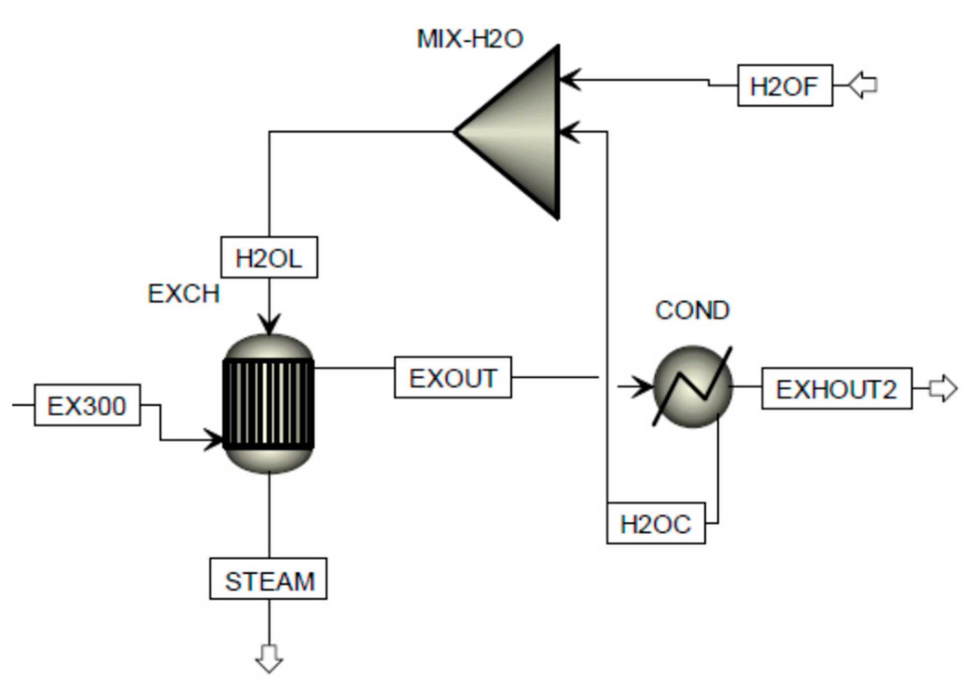
The design of a suitable HRS to be integrated with the SOFC power plant considered some matters related to the specific application on board the ship. Particularly, it must be considered that the heat load demand on board a cruise ship can be considerable. This is fulfilled by producing and distributing steam at about 186 °C and 9 bar. Generally, it is preferred to produce steam through EGBs recovering the heat available from the exhausts of the ICEs in a lower-cost way than using boilers that directly burn fuel. The steam is generated using deionized water produced mainly by multi-flash evaporators and reverses osmosis systems [63]. Due to several harmful compounds, water cannot be condensed from ICEs’ exhausts [64]; instead, if the exhausts are from FC systems, a water recovery seems feasible [65]. According to this latter statement, the HRS proposed in this work integrates a condenser to recover part of the water present in the SOFC exhausts, which is eventually mixed with fresh water and then evaporated to produce steam at 186 °C, as shown in Figure 3. Table 3 contains a brief explanation of the tags used in Figure 3. In this work, the term “freshwater” refers to deionized water produced on board.

2.4. Case Study

The present work considers an LNG-fuelled cruise ship of about 175,000 gross tonnes and 345 m in length. It is supposed to install an SOFC power plant to supply entirely the non-propulsion electric power loads assuming an Integrated Power System (IPS) configuration [66]. The aim is to shut down the ICEs when the cruise ship berths in port to significantly reduce harmful emissions.
Understanding the vessel power demands is necessary for developing an FC strategy that can meet the ship’s requirements; therefore, Table 4 presents the gross electrical and thermal balances for a typical daily operating profile. According to this, the required SOFC power size is about 12 MW, including the electrical power conditioning losses of about 1.5%.
The thermal balance of Table 4 refers to the heat demand (gross and net), the heat recovered, and the thermal power produced by the EGBs for a typical daily operating profile. EGBs produce steam by recovering heat from ICEs’ exhausts only when ICEs are working; as a consequence, in ports, they cannot be used, and the steam has to be produced by boilers. Boilers burn evaporated LNG to produce steam according to the following Equation (2):
BC = 1.75 + 5.74 ∗ L
where BC is the boiler fuel consumption flow rate (kg/h), and L is the thermal load percentage (0–100%).
It must be noted that EGB steam production always meets or exceeds the net heat demand during the navigation (phases P1–P5), while in ports (P6), it must be fulfilled by using boilers.
The DF’s LNG consumption is evaluated by interpolating data presented in Table 5, which are taken from the literature for similar size powers.

3. Results and Discussion

3.1. Heat Recovery System

The validated SOFC model returns the requested data about the exhaust stream (EX300), which are reported in Table 6. It shows in that the exhaust from a 300 kW SOFC system is at 303.3 °C and composed of N2 (74.7 wt%), O2 (11.5 wt%), CO2 (7.3 wt%), and H2O (6.5 wt%).
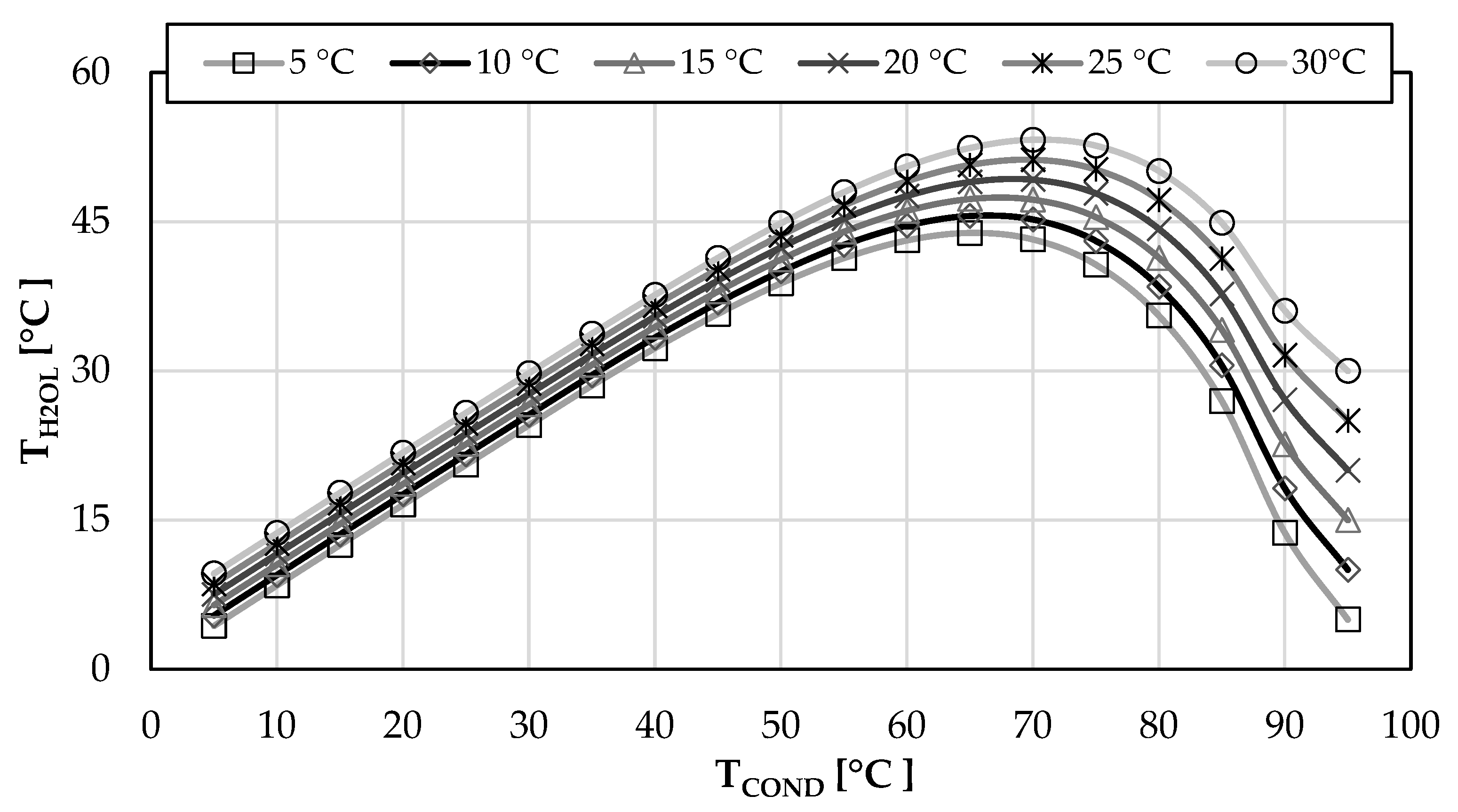
Potentially, a great part of the water contained in the exhaust could be recovered, which means about 3.54 t/h for a 12 MW SOFC power plant. This strongly depends on the temperature of the condenser. Specifically, the graph in Figure 4 shows the condensate stream (H2OC) as a function of the condenser’s working temperature. Temperatures lower than about 45 °C do not significantly affect the condensate flow rate; on the other hand, these could affect the performance of the HRSG because the temperature of the inlet cold stream (H2OL) changes accordingly. The effect of varying the temperature of the H2OC stream is displayed in Figure 5, considering that the temperature of freshwater (H2OF) varies from 5 to 30 °C. The steam production from the HRSG shows peaks with a condenser working temperature in the range of 65–70 °C. These results are strictly related to the grade of preheating of the cold inlet stream (H2OL) to the HRSG, which shows peaks in the same condenser working temperature range, as shown in Figure 6. This trend is due to the fact that increasing the condenser working temperature increases the H2OL temperature favoring steam production; on the other hand, it reduces the H2OC flow rate that balances the cold freshwater stream.
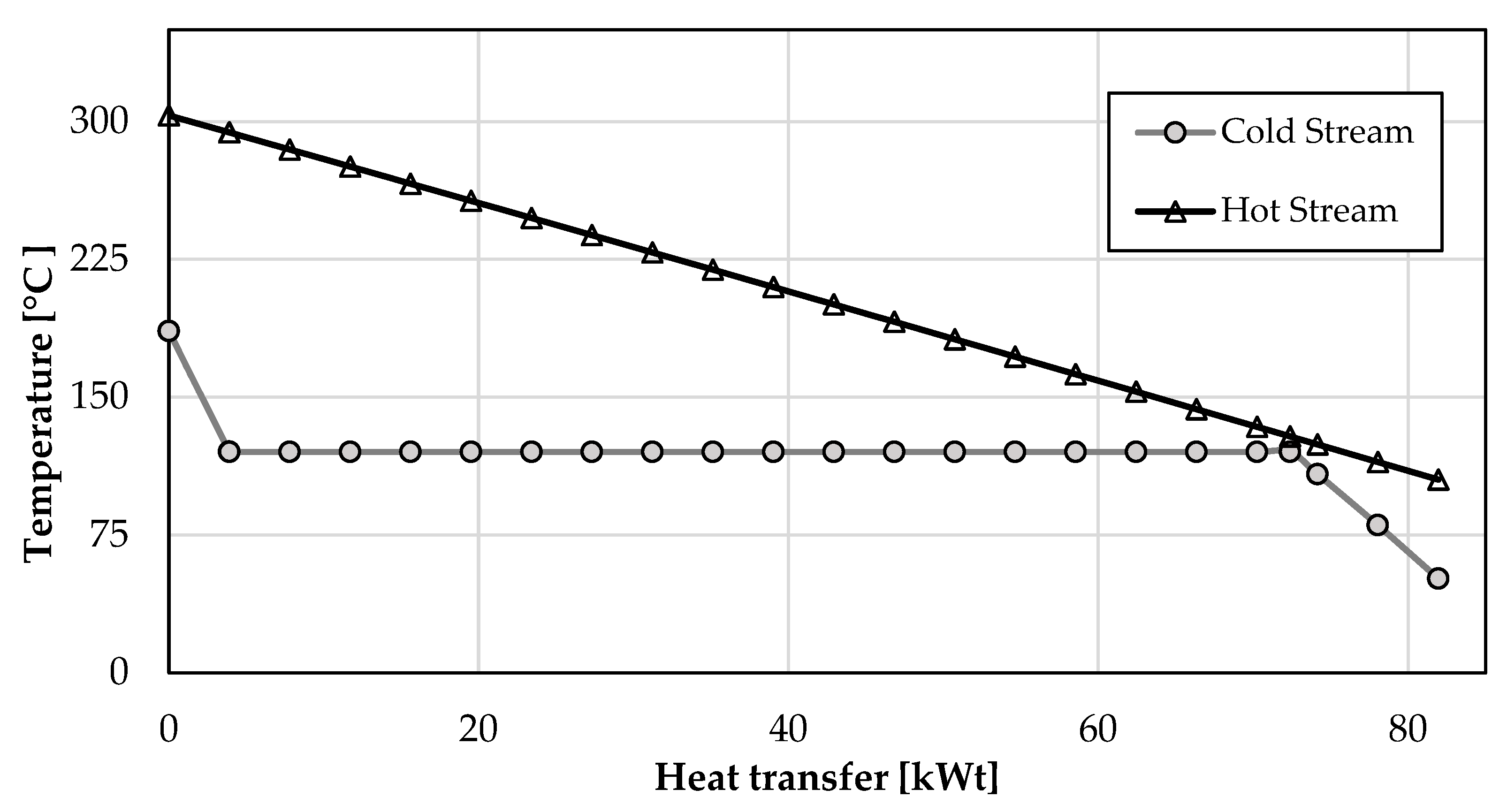
To better understand the heat utilization in the HRSG process, the T–Q diagram of net heat demand and supply is presented in Figure 7 [67,68]. It refers to an optimized HRSG that considers a pinch-point of about 10 °C [69], a condenser working temperature of 70 °C, a freshwater temperature of 25 °C, and a steam production at 186 °C and 2 bar. The HRSG designing was carried out using the “design spec” tool of Aspen Plus, aiming to maximize the steam production; then, the resulting streams’ properties are presented in Table 7. The maximum steam flow rate that can be achieved from a 300 kW SOFC plant is about 111.9 kg/h.
Since the inlet temperature of the hot stream (EX300) and the outlet temperature of the cold stream (STEAM) are defined, the other temperatures are obtained from the optimization procedure. Therefore, the resulting inlet temperature of the cold stream (H2OL) is 51.2 °C, while the outlet temperature of the hot stream (EXOUT) is 105.1 °C (see also Figure 7).
It must be noted that within this preliminary investigation, the solubility of the gas species in the liquid phase is not considered.
Results presented in Table 7 state that about 52% of the water present in the exhaust is condensed to maximize the steam produced by the HRSG. The remaining water can be eventually condensed in an additional condenser to increase the freshwater amount.
A sensitivity analysis was carried out to understand the effect of the LNG stream variation on steam production, which is displayed in Figure 8. As expected, the increase of the LNG stream increases the steam production up to 6.2 kmol/h, which constitutes the maximum productivity for a 75 kW SOFC stack. If the LNG stream exceeds 2 kmol/h, it cannot be totally converted by the SOFC to generate electricity; then, it is sent to another SOFC stack or recycled. On the other hand, the air stream inlet is separated by the LNG stream inlet; therefore, it can be increased in order to cool and control the SOFC system temperature. In any case, it shows that the air stream cannot exceed the value of 54 kmol/h because it would affect the overall thermal balance, and the steam production will decrease.

3.2. Application of HRS to the Case Study

Installing a 12 MW SOFC power plant, integrated with a dedicated HRS, required the adjusting of the initial thermal balance presented in Table 4 for this case study. According to the HRS working condition to maximize the steam production, as described in Section 3.1, the adjusted heat balance is presented in Table 8.
An optimized HRS can produce steam for 3280 kWt. When the cruise ship is navigating (phases P1–P5), the steam production both from the EGBs and the SOFC plant is always higher than the onboard steam/heat demand, as shown in the column named “Net steam”. If the cruise ship berths in port (P6), the SOFC runs at a lower load, generating 8485 kWe, and the HRS produces about 2441 kWt. The heat recovered is not enough to satisfy the onboard heat demand; therefore, the remaining 5597 kWt must be fulfilled by boilers, similar to the prior installation of the SOFC-HRS integrated plant.
The benefits of installing an integrated SOFC-HRS plant on board the cruise ship, aside from the environmental ones, are also evaluated in terms of LNG consumption. Table 9 reports the LNG consumption for the daily navigation profile presented in Table 4 for the initial plant configuration with DFs and EGBs (DF + EGB) and that proposed in the present work (SOFC + HRS). Columns named “W/out SOFC” and “with SOFC” refer respectively to the fuel consumption before and after the installation of the SOFC plant. The overall LNG consumption considers the amounts of LNG consumed by each device (DF, SOFC, and boiler). It shows that in the case of the installation of SOFC-HRS system, the amount of LNG required is about 68.7 t (= 33.7 + 28.1 + 6.9 t), which is lower than the initial amount required, 80.3 t (= 73.1 + 7.2 t). Therefore, the SOFC-HRS system allows the LNG saving of about 14.4% compared to the DF-EGB system.

4. Conclusions

The installation of a 12 MW SOFC power plant on board an LNG-fuelled cruise ship of 345 m in length was considered in order to reduce global emissions, particularly during the mooring in ports, where it would be beneficial to turn off the DF engines.
The SOFC plant is powered by LNG, and the energy produced is intended to supply the hotel loads and provide part of the thermal energy demand through a dedicated HRS. A 0D Aspen Plus model was built-up and validated to simulate the hot streams coming from the SOFC power plant and to assess the performances of the proposed HRS. It was suggested to partially recover the water present in the SOFC exhaust (by 52%), using a condenser working at 70 °C and then to be recycled in an HRSG generating steam at 186 °C and 2 bar. This could reduce the onboard deionized water production and storage.
It was considered a common daily cruise ship profile to compare the SOFC-HRS system to the DF-EGB in terms of LNG consumption, including the LNG consumption of boilers which were used to compensate for the onboard heat demand. It confirmed that the proposed SOFC-HRS integrated system could save up to about 14.4% of LNG.

Author Contributions

Methodology, L.M. and R.R.; Software, R.R.; Validation, L.M.; Investigation, L.M.; Data curation, L.M. and R.R.; Writing—original draft, L.M.; Writing—review & editing, L.M., R.R. and A.P.; Visualization, R.R. and T.C.; Supervision, L.M.; Project administration, L.M. All authors have read and agreed to the published version of the manuscript.

Funding

This research received no external funding.

Data Availability Statement

Not applicable.

Conflicts of Interest

The authors declare no conflict of interest.

References

  1. Joung, T.H.; Kang, S.G.; Lee, J.K.; Ahn, J. The IMO Initial Strategy for Reducing Greenhouse Gas(GHG) Emissions, and Its Follow-up Actions towards 2050. J. Int. Marit. Saf. Environ. Aff. Shipp. 2020, 4, 1–7. [Google Scholar] [CrossRef] [Green Version]
  2. Eyring, V.; Köhler, H.W.; Lauer, A.; Lemper, B. Emissions from International Shipping: 2. Impact of Future Technologies on Scenarios until 2050. J. Geophys. Res. Atmos. 2005, 110, 183–200. [Google Scholar] [CrossRef]
  3. Altosole, M.; Figari, M.; Altosole, M.; Buglioni, G.; Figari, M. Alternative Propulsion Technologies for Fishing Vessels: A Case Study. Int. Rev. Mech. Eng. 2016, 8, 296–301. [Google Scholar]
  4. Altosole, M.; Benvenuto, G.; Campora, U.; Laviola, M.; Altosole, M.; Laviola, M.; Trucco, A.; SpA, F. Waste Heat Recovery Systems from Marine Diesel Engines: Comparison between New Design and Retrofitting Solutions. Energies 2015, 10, 718. [Google Scholar] [CrossRef] [Green Version]
  5. Mazzoccoli, M.; Altosole, M.; Vigna, V.; Bosio, B.; Arato, E. Marine Pollution Mitigation by Waste Oils Recycling Onboard Ships: Technical Feasibility and Need for New Policy and Regulations. Front. Mar. Sci. 2020, 7, 566363. [Google Scholar] [CrossRef]
  6. Altosole, M.; Campora, U.; Mocerino, L.; Zaccone, R. An Innovative Variable Layout Steam Plant for Waste Heat Recovery from Marine Dual-Fuel Engines. Ships Offshore Struct. 2022, 18, 429–437. [Google Scholar] [CrossRef]
  7. Altosole, M.; Balsamo, F.; Campora, U.; Mocerino, L. Marine Dual-Fuel Engines Power Smart Management by Hybrid Turbocharging Systems. J. Mar. Sci. Eng. 2021, 9, 663. [Google Scholar] [CrossRef]
  8. Altosole, M.; Benvenuto, G.; Campora, U.; Silvestro, F.; Terlizzi, G. Efficiency Improvement of a Natural Gas Marine Engine Using a Hybrid Turbocharger. Energies 2018, 11, 1924. [Google Scholar] [CrossRef] [Green Version]
  9. Qin, T.; Yuan, S. Research Progress of Catalysts for Catalytic Steam Reforming of High Temperature Tar: A Review. Fuel 2023, 331, 125790. [Google Scholar] [CrossRef]
  10. van Biert, L.; Godjevac, M.; Visser, K.; Aravind, P.V. A Review of Fuel Cell Systems for Maritime Applications. J. Power Sources 2016, 327, 345–364. [Google Scholar] [CrossRef] [Green Version]
  11. Xing, H.; Stuart, C.; Spence, S.; Chen, H. Fuel Cell Power Systems for Maritime Applications: Progress and Perspectives. Sustainability 2021, 13, 1213. [Google Scholar] [CrossRef]
  12. Coraddu, A.; Gil, A.; Akhmetov, B.; Yang, L.; Romagnoli, A.; Ritari, A.; Huotari, J.; Tammi, K. Energy Storage on Ships. In Sustainable Energy Systems on Ships; Elsevier: Amsterdam, The Netherlands, 2022; pp. 197–232. [Google Scholar] [CrossRef]
  13. Okubo, M.; Kuwahara, T. Prospects for Marine Diesel Engine Emission Control. In New Technologies for Emission Control in Marine Diesel Engines; Elsevier: Amsterdam, The Netherlands, 2020; pp. 211–266. [Google Scholar] [CrossRef]
  14. IMO’s Work to Cut GHG Emissions from Ships. Available online: https://www.imo.org/en/MediaCentre/HotTopics/Pages/Cutting-GHG-emissions.aspx (accessed on 28 April 2022).
  15. IMO Cutting GHG Emissions from Shipping—10 Years of Mandatory Rules. Available online: https://gmn.imo.org/cutting-ghg-emission-from-shipping-10-years-of-mandatory-rules/ (accessed on 28 April 2022).
  16. Aakko-Saksa, P.T.; Lehtoranta, K.; Kuittinen, N.; Järvinen, A.; Jalkanen, J.P.; Johnson, K.; Jung, H.; Ntziachristos, L.; Gagné, S.; Takahashi, C.; et al. Reduction in Greenhouse Gas and Other Emissions from Ship Engines: Current Trends and Future Options. Prog. Energy Combust. Sci. 2023, 94, 101055. [Google Scholar] [CrossRef]
  17. Bouman, E.A.; Lindstad, E.; Rialland, A.I.; Strømman, A.H. State-of-the-Art Technologies, Measures, and Potential for Reducing GHG Emissions from Shipping—A Review. Transp. Res. Part D Transp. Environ. 2017, 52, 408–421. [Google Scholar] [CrossRef]
  18. Coralli, A.; Sarruf, B.J.M.; De Miranda, P.E.V.; Osmieri, L.; Specchia, S.; Minh, N.Q. Fuel Cells. In Science and Engineering of Hydrogen-Based Energy Technologies: Hydrogen Production and Practical Applications in Energy Generation; Academic Press: Cambridge, MA, USA, 2019; pp. 39–122. [Google Scholar] [CrossRef]
  19. Breeze, P.; Breeze, P. Chapter 7—Fuel Cells. In Power Generation Technologies; Elsevier: Amsterdam, The Netherlands, 2019. [Google Scholar] [CrossRef]
  20. Dicks, A.L.; Rand, D.A.J. Fuel Cell Systems Explained; John Wiley & Sons Ltd.: New York, NY, USA, 2018. [Google Scholar] [CrossRef]
  21. Fuel Cell Industry Review. 2021. Available online: https://www.e4tech.com/resources/249-fuel-cell-industry-review-2021.php (accessed on 19 November 2022).
  22. Tronstad, T.; Høgmoen, Å.H.; Haugom, G.P.; Langfeldt, L. Study on the Use of Fuel Cells in Shipping. Study Commissioned by European Maritime Safety Agency (EMSA); EMSA European Maritime Safety Agency: Lisboa, Portugal, 2017. [Google Scholar]
  23. Coppola, T.; Micoli, L.; Turco, M. State of the Art of High Temperature Fuel Cells in Maritime Applications. In Proceedings of the 2020 International Symposium on Power Electronics, Electrical Drives, Automation and Motion (SPEEDAM), Sorrento, Italy, 24–26 June 2020; pp. 430–435. [Google Scholar] [CrossRef]
  24. Singla, M.K.; Nijhawan, P.; Oberoi, A.S. Hydrogen Fuel and Fuel Cell Technology for Cleaner Future: A Review. Environ. Sci. Pollut. Res. 2021, 28, 15607–15626. [Google Scholar] [CrossRef] [PubMed]
  25. Rosli, R.E.; Sulong, A.B.; Daud, W.R.W.; Zulkifley, M.A.; Husaini, T.; Rosli, M.I.; Majlan, E.H.; Haque, M.A. A Review of High-Temperature Proton Exchange Membrane Fuel Cell (HT-PEMFC) System. Int. J. Hydrogen Energy 2017, 42, 9293–9314. [Google Scholar] [CrossRef]
  26. Raza, T.; Yang, J.; Wang, R.; Xia, C.; Raza, R.; Zhu, B.; Yun, S. Recent Advance in Physical Description and Material Development for Single Component SOFC: A Mini-Review. Chem. Eng. J. 2022, 444, 136533. [Google Scholar] [CrossRef]
  27. McPhail, S.J.; Conti, B.; Kiviaho, J. The Yellow Pages of SOFC Technology—International Status of SOFC Deployment 2017; International Energy Agency: Paris, France, 2017; ISBN 978-88-8286-290-9. [Google Scholar]
  28. Paściak, G.; Chmielowiec, J.; Bujło, P. New Ceramic Superionic Materials for IT-SOFC Applications. Mater. Sci.-Pol. 2005, 23, 209–219. [Google Scholar]
  29. Liu, Y.; Shao, Z.; Mori, T.; Jiang, S.P. Development of Nickel Based Cermet Anode Materials in Solid Oxide Fuel Cells—Now and Future. Mater. Rep. Energy 2021, 1, 100003. [Google Scholar] [CrossRef]
  30. Ma, M.; Yang, X.; Qiao, J.; Sun, W.; Wang, Z.; Sun, K. Progress and Challenges of Carbon-Fueled Solid Oxide Fuel Cells Anode. J. Energy Chem. 2021, 56, 209–222. [Google Scholar] [CrossRef]
  31. Solovyev, A.A.; Shipilova, A.V.; Rabotkin, S.V.; Bogdanovich, N.M.; Pikalova, E.Y. Study of the Efficiency of Composite LaNi0.6Fe0.4O3-Based Cathodes in Intermediate-Temperature Anode-Supported SOFCs. Int. J. Hydrogen Energy 2023, in press. [Google Scholar] [CrossRef]
  32. Tahir, N.N.M.; Baharuddin, N.A.; Samat, A.A.; Osman, N.; Somalu, M.R. A Review on Cathode Materials for Conventional and Proton-Conducting Solid Oxide Fuel Cells. J. Alloys Compd. 2022, 894, 162458. [Google Scholar] [CrossRef]
  33. Sazali, N.; Salleh, W.N.W.; Jamaludin, A.S.; Razali, M.N.M. New Perspectives on Fuel Cell Technology: A Brief Review. Membranes 2020, 10, 99. [Google Scholar] [CrossRef]
  34. Braun, R.J.; Kazempoor, P. Application of SOFCs in Combined Heat, Cooling and Power Systems. In Solid Oxide Fuel Cells; Royal Society of Chemistry: London, UK, 2013. [Google Scholar]
  35. Ellamla, H.R.; Staffell, I.; Bujlo, P.; Pollet, B.G.; Pasupathi, S. Current Status of Fuel Cell Based Combined Heat and Power Systems for Residential Sector. J. Power Sources 2015, 293, 312–328. [Google Scholar] [CrossRef]
  36. Baldi, F.; Moret, S.; Tammi, K.; Maréchal, F. The Role of Solid Oxide Fuel Cells in Future Ship Energy Systems. Energy 2020, 194, 116811. [Google Scholar] [CrossRef]
  37. Micoli, L.; Coppola, T.; Turco, M. A Case Study of a Solid Oxide Fuel Cell Plant on Board a Cruise Ship. J. Mar. Sci. Appl. 2021, 20, 524–533. [Google Scholar] [CrossRef]
  38. Perčić, M.; Vladimir, N.; Jovanović, I.; Koričan, M. Application of Fuel Cells with Zero-Carbon Fuels in Short-Sea Shipping. Appl. Energy 2022, 309, 118463. [Google Scholar] [CrossRef]
  39. Singh, D.V.; Pedersen, E. A Review of Waste Heat Recovery Technologies for Maritime Applications. Energy Convers. Manag. 2016, 111, 315–328. [Google Scholar] [CrossRef]
  40. Jouhara, H.; Khordehgah, N.; Almahmoud, S.; Delpech, B.; Chauhan, A.; Tassou, S.A. Waste Heat Recovery Technologies and Applications. Therm. Sci. Eng. Prog. 2018, 6, 268–289. [Google Scholar] [CrossRef]
  41. Shu, G.; Liang, Y.; Wei, H.; Tian, H.; Zhao, J.; Liu, L. A Review of Waste Heat Recovery on Two-Stroke IC Engine Aboard Ships. Renew. Sustain. Energy Rev. 2013, 19, 385–401. [Google Scholar] [CrossRef]
  42. Shu, G.; Liu, P.; Tian, H.; Wang, X.; Jing, D. Operational Profile Based Thermal-Economic Analysis on an Organic Rankine Cycle Using for Harvesting Marine Engine’s Exhaust Waste Heat. Energy Convers. Manag. 2017, 146, 107–123. [Google Scholar] [CrossRef]
  43. Ouyang, T.; Wang, Z.; Zhao, Z.; Lu, J.; Zhang, M. An Advanced Marine Engine Waste Heat Utilization Scheme: Electricity-Cooling Cogeneration System Integrated with Heat Storage Device. Energy Convers. Manag. 2021, 235, 113955. [Google Scholar] [CrossRef]
  44. Alirahmi, S.M.; Gundersen, T.; Yu, H. A Comprehensive Study and Tri-Objective Optimization for an Efficient Waste Heat Recovery from Solid Oxide Fuel Cell. Int. J. Hydrogen Energy 2023, in press. [CrossRef]
  45. Ouyang, T.; Zhao, Z.; Su, Z.; Lu, J.; Wang, Z.; Huang, H. An Integrated Solution to Harvest the Waste Heat from a Large Marine Solid Oxide Fuel Cell. Energy Convers. Manag. 2020, 223, 113318. [Google Scholar] [CrossRef]
  46. Zhang, H.; Kong, W.; Dong, F.; Xu, H.; Chen, B.; Ni, M. Application of Cascading Thermoelectric Generator and Cooler for Waste Heat Recovery from Solid Oxide Fuel Cells. Energy Convers. Manag. 2017, 148, 1382–1390. [Google Scholar] [CrossRef]
  47. Doherty, W.; Reynolds, A.; Kennedy, D. Process Simulation of Biomass Gasification Integrated with a Solid Oxide Fuel Cell Stack. J. Power Sources 2015, 277, 292–303. [Google Scholar] [CrossRef] [Green Version]
  48. Doherty, W.; Reynolds, A.; Kennedy, D. Computer Simulation of a Biomass Gasification-Solid Oxide Fuel Cell Power System Using Aspen Plus. Energy 2010, 35, 4545–4555. [Google Scholar] [CrossRef] [Green Version]
  49. Corigliano, O.; Pagnotta, L.; Fragiacomo, P. On the Technology of Solid Oxide Fuel Cell (SOFC) Energy Systems for Stationary Power Generation: A Review. Sustainability 2022, 14, 15276. [Google Scholar] [CrossRef]
  50. Wain-Martin, A.; Campana, R.; Morán-Ruiz, A.; Larrañaga, A.; Arriortua, M.I. Synthesis and Processing of SOFC Components for the Fabrication and Characterization of Anode Supported Cells. Boletín Soc. Española Cerámica Vidr. 2022, 61, 264–274. [Google Scholar] [CrossRef]
  51. Zamudio-García, J.; Caizán-Juanarena, L.; Porras-Vázquez, J.M.; Losilla, E.R.; Marrero-López, D. A Review on Recent Advances and Trends in Symmetrical Electrodes for Solid Oxide Cells. J. Power Sources 2022, 520, 230852. [Google Scholar] [CrossRef]
  52. Cigolotti, V.; Genovese, M.; Fragiacomo, P. Comprehensive Review on Fuel Cell Technology for Stationary Applications as Sustainable and Efficient Poly-Generation Energy Systems. Energies 2021, 14, 4963. [Google Scholar] [CrossRef]
  53. Bove, R.; Ubertini, S. Modeling Solid Oxide Fuel Cell Operation: Approaches, Techniques and Results. J. Power Sources 2006, 159, 543–559. [Google Scholar] [CrossRef]
  54. Huang, K.; Goodenough, J.B. Solid Oxide Fuel Cell Technology: Principles, Performance and Operations. In Solid Oxide Fuel Cell Technology: Principles, Performance and Operations; Elsevier: Amsterdam, The Netherlands, 2009; pp. 1–328. [Google Scholar] [CrossRef]
  55. Sharaf, O.Z.; Orhan, M.F. An Overview of Fuel Cell Technology: Fundamentals and Applications. Renew. Sustain. Energy Rev. 2014, 32, 810–853. [Google Scholar] [CrossRef]
  56. Koh, J.; Yoo, Y.; Park, J.; Ionics, H.L.-S.S. Carbon Deposition and Cell Performance of Ni-YSZ Anode Support SOFC with Methane Fuel. Solid State Ion. 2002, 149, 157–166. [Google Scholar] [CrossRef]
  57. Ke, K.; Gunji, A.; Mori, H.; Tsuchida, S.; Takahashi, H.; Ionics, K.U.-S.S. Effect of Oxide on Carbon Deposition Behavior of CH4 Fuel on Ni/ScSZ Cermet Anode in High Temperature SOFCs. Solid State Ion. 2006, 177, 541–547. [Google Scholar] [CrossRef]
  58. Lee, W.Y.; Hanna, J.; Ghoniem, A.F. On the Predictions of Carbon Deposition on the Nickel Anode of a SOFC and Its Impact on Open-Circuit Conditions. J. Electrochem. Soc. 2013, 160, F94–F105. [Google Scholar] [CrossRef]
  59. Hall, D.J.; Colclaser, R.G. Transient Modeling and Simulation of a Tubular Solid Oxide Fuel Cell. IEEE Trans. Energy Convers. 1999, 14, 749–753. [Google Scholar] [CrossRef]
  60. Hofmann, P.; Panopoulos, K.D.; Fryda, L.E.; Kakaras, E. Comparison between Two Methane Reforming Models Applied to a Quasi-Two-Dimensional Planar Solid Oxide Fuel Cell Model. Energy 2009, 34, 2151–2157. [Google Scholar] [CrossRef]
  61. Panopoulos, K.D.; Fryda, L.; Karl, J.; Poulou, S.; Kakaras, E. High Temperature Solid Oxide Fuel Cell Integrated with Novel Allothermal Biomass Gasification: Part II: Exergy Analysis. J. Power Sources 2006, 159, 586–594. [Google Scholar] [CrossRef]
  62. Yi, J.H.; Kim, T.S. Effects of Fuel Utilization on Performance of SOFC/Gas Turbine Combined Power Generation Systems. J. Mech. Sci. Technol. 2017, 31, 3091–3100. [Google Scholar] [CrossRef]
  63. Bolonkin, A.A.; Neumann, S.; Friedlander, J.J. A Novel Macro-Engineering Approach to Seawater Desalination. Environ. Sci. Eng. 2011, 1, 675–689. [Google Scholar] [CrossRef]
  64. Mocerino, L.; Soares, C.G.; Rizzuto, E.; Balsamo, F.; Quaranta, F. Validation of an Emission Model for a Marine Diesel Engine with Data from Sea Operations. J. Mar. Sci. Appl. 2021, 20, 534–545. [Google Scholar] [CrossRef]
  65. Nguyen, T.V. Water Management by Material Design and Engineering for PEM Fuel Cells. ECS Trans. 2006, 3, 1171–1180. [Google Scholar] [CrossRef]
  66. Patel, M. Shipboard Electrical Power Systems; CRC Press: Boca Raton, FL, USA, 2021. [Google Scholar]
  67. Men, Y.; Liu, X.; Zhang, T. Performance Comparison of Different Total Heat Exchangers Applied for Waste Heat Recovery. Appl. Therm. Eng. 2021, 182, 115715. [Google Scholar] [CrossRef]
  68. Itoh, J.; Shiroko, K.; Umeda, T. Extensive Applications of the T-Q Diagram to Heat Integrated System Synthesis. Comput. Chem. Eng. 1986, 10, 59–66. [Google Scholar] [CrossRef]
  69. Min, G.; Park, Y.J.; Hong, J. Thermodynamic Analysis of a Solid Oxide Co-Electrolysis Cell System for Its Optimal Thermal Integration with External Heat Supply. Energy Convers. Manag. 2020, 225, 113381. [Google Scholar] [CrossRef]
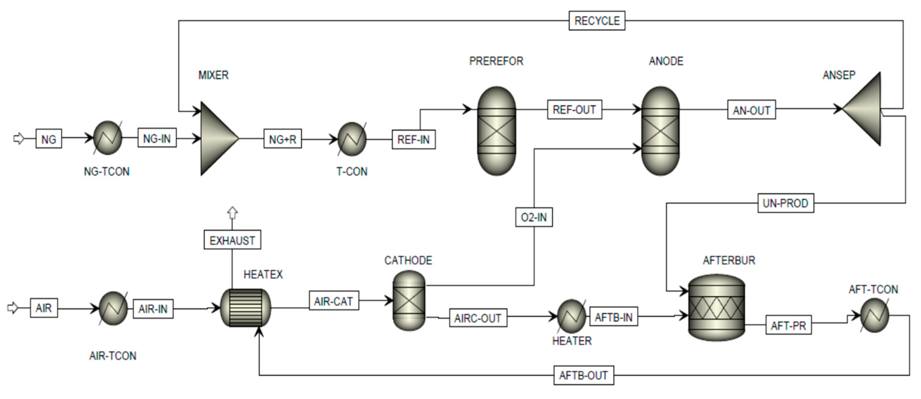
Figure 1. SOFC power generator system flowsheet built-in in Aspen Plus.
Energies 16 03334 g001
Figure 2. Exhaust temperature variation as a function of the airflow rate.
Energies 16 03334 g002
Figure 3. Steam generator system flowsheet.
Energies 16 03334 g003
Figure 4. Condensate stream as a function of the condenser working temperature (TCOND).
Energies 16 03334 g004
Figure 5. HRSG steam production as a function of the condenser working temperature (TCOND) varying the freshwater temperature from 5 °C to 30 °C.
Energies 16 03334 g005
Figure 6. Variation of the inlet temperature of the cold inlet stream (TH2OL) to the HRSG as a function of the condenser working temperature (TCOND) varying the freshwater temperature from 5 °C to 30 °C.
Energies 16 03334 g006
Figure 7. T–Q diagrams of the heat exchange process in the HRSG unit.
Energies 16 03334 g007
Figure 8. Effect of the LNG stream variation on air inlet stream and the steam production.
Energies 16 03334 g008
Table 1. Description of Aspen Plus unit operation blocks of the flowsheet presented in Figure 1.
Block IDAspen Plus Unit BlockDescription
NG-TCONHeaterSets the fuel inlet temperature
MIXERMixerMixes the recycled unconverted fuel with fresh fuel
T-CONHeaterPreheats the inlet stream to the reformer reactor up to 850 °C
PREREFORRGibbs (Gibbs free energy reactor)Simulates steam reforming of CH4 of lighter hydrocarbons and the shifting of CO to H2 (Water–Gas Shift reaction)
ANODERGibbs (Gibbs free energy reactor)Simulates the reforming and electrochemical reactions occurring at the anode
ANSEPFSplit (Splitter)Splits the anode outlet into a recycle stream and a stream sent to the afterburner
AFTERBURRStoic (Stoichiometric reactor)Simulates the complete combustion of the remaining fuel with the depleted oxidant
AFT-TCONHeaterManages the overall heat balance
HEATERHeaterSets the cathode temperature at 900 °C
CATHODESep (Separator)Simulates the cathode and the electrolyte ion flow separating the O2 required by the electrochemical reactions from the air inlet stream
HEATEXHeatX (Heat exchanger)Preheats the inlet air using the hot gases from the afterburner
AIR-TCONHeaterSets the air inlet temperature
Table 2. SOFC power plant model input parameters.
InputValue
LNG composition [% vol]CH4: 90; C2H6: 8; C3H8: 2
Air composition [% vol]N2: 78.5; O2: 20; H2O: 1.5
SOFC-operating temperature [°C]900
SOFC-operating pressure [bar]2
SOFC efficiency [%]60
DC stack power [kW]75
Anodic recycle ratio [%]85
Fuel-utilization factor [%]67
Reformer-operating temperature [°C]850
Thermal losses [%]3
Table 3. Description of Aspen Plus unit operation blocks and streams of the flowsheet presented in Figure 3.
Block/Stream IDAspen Plus Unit Block/StreamDescription
EXCHHeateX
(Heat exchanger)
Simulates a Heat Recovery Steam Generator (HRSG).
MIX-H2OMixerMixes the condensed and freshwater streams
CONDHeaterSimulates a condenser
EX300StreamExhaust stream from the SOFC plant (at an average temperature of about 300 °C)
STEAMStreamSteam, produced at 186 °C and 2 bar
H2OLStreamWater stream to be vaporized
EXOUTStreamCooled exhaust stream from the HRSG
H2OFStreamFreshwater stream at 25 °C
H2OCStreamCondensed water from the exhaust stream
EXHOUT2StreamWater-depleted exhaust stream
Table 4. Gross electrical and thermal balances of the cruise ship for a typical daily operating profile.
Phase IDDuration
[h]
Speed
[kn]
Propulsion Power at MSB *
[kWe]
Non-Prop. Electric Power
[kWe]
Total Electric Power at MSB *
[kWe]
Heat
Demand [kWt]
Heat
Recovered [kWt]
Heat
Demand (Net)
[kWt]
EGB Steam
Production
[kWt]
P1713.012,42711,81024,23715,448665187978804
P2316.017,24611,81029,05617,417842489939309
P3118.323,57211,81035,38220,897911811,77912,207
P40.520.533,19311,81045,00324,98912,02112,96814,256
P50.521.538,27411,81051,44924,93112,36012,57116,434
P6120-8485848510,920288280380
* MSB = main switchboard.
Table 5. Specific LNG consumption of the DF.
PowerSpecific LNG Consumption
[kWe][kg/h]
11,3281828
84851362
80851296
Table 6. Inlet and outlet streams of a 300 kW SOFC system.
Stream ID
AIRNGEX300
Mass Flow by Component [kg/h]
O2294.90156
N21013.301013.3
H2O12.5088.5
CH4028.80
C2H604.80
C3H801.80
CO20098.2
Total mass flow [kg/h]1320.735.31356
Total mole flow [kmol/h]46.1248.2
Total volume flow [m3/h]561.6 24.3 1154.9
Temperature [°C]2020303.3
Table 7. Streams’ properties of the optimized HRS for a 300 kW SOFC plant.
EX300EXHOUT2EXOUTH2OCH2OFH2OLSTEAM
Mass Flow by Component [kg/h]
O21561561560000
N21013.31013.31013.30000
H2O88.522.888.565.746.2111.9111.9
CO298.298.298.20000
Total mass flow [kg/h]13561290.3135665.746.2111.9111.9
Total mole flow [kmol/h]48.244.548.23.72.66.26.2
Total volume flow [m3/h]1154.9 635.4 757.8 0.067 0.0480.12 118.6
Temperature [°C]303.370105.1702551.2186
Table 8. Adjusted heat balance of the cruise ship with the SOFC power plant integrated with the heat recovery system.
Phase IDHRS Steam ProductionNet SteamBoiler Steam Production
[kWt][kWt][kWt]
P132803287-
P232803596-
P332803708-
P432804568-
P532807143-
P62441−55975597
Table 9. Comparison of daily LNG consumption for two different exhaust heat recovery configurations (DF + EGB and SOFC + HRS) and boilers.
Phase IDLNG Consumption [kg]
DF + EGBSOFC + HRSBOILER
W/out SOFCWith SOFC W/out SOFCWith SOFC
P128,08114,8739392--
P214,42787674025--
P3585639691342--
P437242781671--
P542693323671--
P616,741011,98471506905
Total P [1,2,3,4,5,6]73,09933,71328,08671506905
Disclaimer/Publisher’s Note: The statements, opinions and data contained in all publications are solely those of the individual author(s) and contributor(s) and not of MDPI and/or the editor(s). MDPI and/or the editor(s) disclaim responsibility for any injury to people or property resulting from any ideas, methods, instructions or products referred to in the content.