Article

Charge Equalization System for an Electric Vehicle with a Solar Panel

by
Darwin-Alexander Angamarca-Avendaño
1,*,
Jonnathan-Francisco Saquicela-Moncayo
1,
Byron-Humberto Capa-Carrillo
1 and
Juan-Carlos Cobos-Torres
1,2,*
1
Unidad Académica de Ingeniería Industria y Construcción (Ingeniería Eléctrica), Universidad Católica de Cuenca, Cuenca 010105, Ecuador
2
Unidad Académica de Posgrado, Universidad Católica de Cuenca, Cuenca 010107, Ecuador
*
Authors to whom correspondence should be addressed.
Energies 2023, 16(8), 3360; https://doi.org/10.3390/en16083360
Submission received: 28 February 2023 / Revised: 21 March 2023 / Accepted: 25 March 2023 / Published: 11 April 2023
(This article belongs to the Special Issue Advanced Technologies in New Energy Vehicle)

Abstract

:
Electric vehicles are environmentally friendly and more efficient than conventional combustion vehicles. However, from the point of view of energy vectors, they may use energy produced by less efficient and more polluting means. In this paper, an applicative methodology is used to develop a charging equalizer for an electric vehicle that makes it possible to efficiently use the energy produced by a 350 W photovoltaic panel to intelligently charge the five batteries of the vehicle. In addition, using a quantitative methodology, an analysis of the different physical and electrical parameters obtained by a series of sensors installed in the vehicle is presented, and the efficiency of the system is determined. Different routes were travelled within the city of Cuenca with and without the load equalization system, which made it possible to determine an increase in vehicle efficiency of up to 27.9%, equivalent to an additional travel distance of approximately 14.35 km. This is a promising result, since with small investments in solar panels and electronic materials, the performance of low-cost electric vehicles can be significantly improved.

1. Introduction

The acceleration in the growth of the population is remarkable; today, 55% of people live in cities, and it is estimated that by 2050, the urban population will increase considerably, with double the current number of existing inhabitants. It is projected that 7 out of 10 people will live in urban areas [1]. Energy consumption in cities is currently high, imposing a demand for more than 75% of global energy production and causing about 80% of greenhouse gas (GHG) emissions [2]. Internal combustion vehicles are the primary source of pollutants in cities as they can emit more than 1000 different harmful substances [3].
Approximately 75% of mobility in urban areas is achieved via combustion vehicles. In recent years, in many Latin American countries, there has been an annual growth rate of equivalent to 4.7% in the vehicle sector. In 2015, motorization in Latin America reached an average of 201 vehicles per 1000 inhabitants [4]. An internal combustion vehicle has an energy efficiency ranging from 20% to 30%; in contrast, an electric vehicle (EV) is more efficient, with an energy efficiency exceeding 90%, and has a productivity three times higher than a combustion vehicle [5]. An additional advantage is that these vehicles do not consume energy when stopped, unlike combustion engines that continue to consume fuel when idling.
The use of EVs is one of the viable alternatives for reducing GHGs [6]. According to Transport and Environment (T&E), EVs emit carbon dioxide at rates up to three times lower than combustion vehicles. T&E also estimates that the greater the amount of electric power produced by renewables in the coming years, EVs could pollute up to four times less than combustion vehicles [7].
The term ‘vehicle-integrated photovoltaic’ (VIPV) has been used to refer to the use of photovoltaic panels in EVs, which are intended to cover their energy needs via solar energy. Ota, Araki, Nagaoka, and Nishioka [8] have determined that the top of the vehicle (roof) is the most efficient place for the placement of a photovoltaic (PV) panel, as it receives the majority of direct solar radiation. A VIPV can be installed on the roof in many different ways, according to the consumer’s preference, without having to design a roof to contain the PV.
There are many applications of PVs in EVs, and in view of this, Sinuraya, Sinaga, Simamora, and Wahyudi [9] designed a battery charging system using four 100 W monocrystalline-type PVs to supply energy to an EV with a 1 kW motor (2022). With this system, an additional autonomy of 1.2 h was achieved when the system was fully charged. Similarly, Yu, Zhu, Liu, and Zhang [10] presented an on-board charger built with electric drives that powered a 2 kW prototype motor using solar energy. Charging and driving operations could be carried out simultaneously, thus significantly extending the mileage range of EVs by capturing solar radiation. Srivastava, Karthikeyan, Arumugam, Kumar, and Thanigaivel [11] presented a similar study in which an EV operating at 48 V had a thin film PV installed on the roof, with the aim of meeting the power demand of the air-conditioning system. Likewise, Mil’shtein, Zinaddinov, Asthana, and Scheminger [12] designed and tested a lightweight all-wheel drive EV. The car could carry four passengers and an additional attached load of about 500 kg. It relied on a battery block of LiFePO4 cells with a power of 6000 W. On the roof, a 600 W PV was installed, which constantly recharged the lithium-ion batteries. A similar approach was applied in Japan, where hybrid tourism vehicles with PV were tested [13]. Calculations showed that the PVs had an excellent energy capacity, generating 2.1 kWh/day, meaning that GHGs were decreased by 63%. Sekhar, Krishna, Abhimanue, Meeran, and Janardhanan [14] focused on transforming the shape of the sunroof of an EV from the SCMS School of Engineering and Technology into an aerodynamic form.
A study by Alvarez-Diazcomas et al. [15] presented a bidirectional DC-DC power converter with multiple inputs that could interface with two or more power supplies with various voltage levels. This converter simultaneously controlled the power drawn from each power supply independently. In addition, it allowed for grid interaction when charging the battery and ultracapacitors, enabling power delivery from these components. In another research paper [16], the same author proposed a topology that could transfer power from one cell to an adjacent cell, or one string to an adjacent string. PSIM software was applied to validate the theoretical analysis. Simulations were carried out which demonstrated the correct operation of the proposed equalizer. At the same time, the equalization time and the current and voltage ripple in the converter MOSFETs were reduced. Similarly, the studies in [17,18] showed that battery equalization circuits for electric vehicles are essential to maintain a charge balance and prolong battery life. These are key components of EVs, and their energy storage capacity determines the distance an EV can travel on a single charge. However, they are subject to degradation and ageing, which can reduce their energy storage capacity and shorten their lifespan.
It has been estimated that the PV energy required for an EV to be independent of the grid is 1.27 kW, to be used at 100% of its optimum capacity. However, due to the limited area over which a panel of this capacity can be installed in the vehicle, it needs to have a conversion efficiency of 30% or higher [14]. To increase the efficiency of the EV, several conditions should be met; a PV is needed whose cell modules are highly efficient, and adequate solar radiation conditions are required. An example of a three-junction solar module based on III-V technology was implemented in an EV, resulting in a considerable increase in the autonomy of the vehicle. An increased distance of 30 km per day was achieved and, at times when the solar index was higher, this could be improved to 50 km [19].
The use of PV cells offers an alternative for generating energy for EVs by improving their efficiency; however, the average efficiency of the solar energy conversion of PVs is currently between 20% and 30%, meaning that too much energy is lost. As a result, most EVs today rely on external power. Nevertheless, in the future, with improved PV technology in which solar energy is used better, the total autonomy of the vehicle could be achieved [20]. The generation of PV energy in Ecuador benefits from its geographical location: as it is located on the equatorial line, solar radiation is almost constant throughout the year, and only varies in the rainy seasons [21]. For this reason, the use of this energy can be optimized for electromobility, increasing the autonomy of EVs and promoting clean, safe, and efficient transportation. This conclusion can be corroborated by the Bristow and Campbell model, which was used to estimate that the solar radiation in Cuenca in 2014 was 15,367 MJ m2 per day, equivalent to 4686 kWh. In addition, considering that the urban area of Cuenca has a clean atmosphere, the use of this energy will help the installation of PVs in this region to achieve a higher efficiency in terms of energy production, reaching 12–16% [22]. EVs have many advantages over internal combustion vehicles; for example, from an environmental perspective, they significantly reduce the emission of GHGs. However, their main disadvantage is that they cannot travel long distances, as this causes significant wear and tear on batteries. Long periods are therefore required for recharging EV batteries, and, as a result, most people choose to use conventional vehicles.
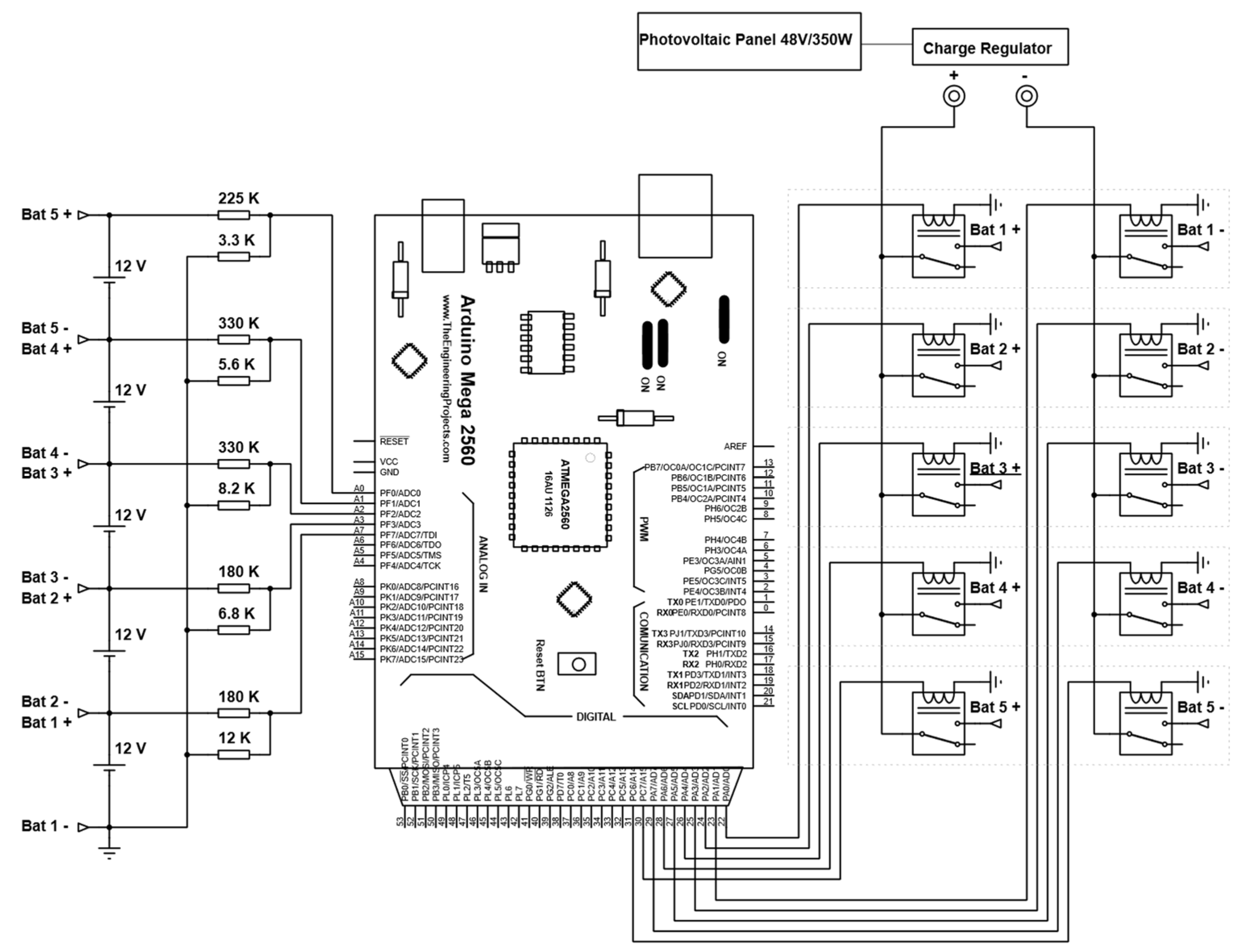
In view of the advantages and disadvantages mentioned above, the aim of this study is to improve the autonomy of an EV. To achieve this goal, the paper is structured as follows. Section 2 describes the proposed hardware architecture, which includes the set of electrical components and sensors required for the operation of the system. The software design is divided into four parts: data acquisition, battery charging, data storage, and data visualization. The charging equalizer design consists of a set of 10 relays that are connected by wired logic and used to individually charge the 5 batteries of the EV, which are connected in series. In Section 3, the data obtained from a comparison of the system with and without PV are presented. When designing the system model, a DIY methodology was used that encouraged the development of creativity, with a focus on self-management and self-production. Finally, conclusions and a general discussion of the project are presented.
The main contribution of this study is a demonstration that the energy generated by the PV can be better utilized by implementing a charging equalizer. The traditional charging process of batteries treats them as a whole, with the result that some batteries are not fully charged. Furthermore, by installing a series of sensors for physical parameters such as inclination (mpu-9250) and location (GPS-neo-6m), and electrical parameters such as voltages (voltage dividers) and currents (SCT-013), it was possible to monitor the behavior of the vehicle. These data were needed to determine the efficiency of the system, and for future research.

2. Materials and Methods

The present research was conducted in two phases. In the first, an applicative methodology was used to develop a system for load equalization and a measurement of the physical and electrical signals of the EV. Following this, a quantitative method was used to analyze all the information collected over journeys with and without the proposed system, which were carried out in Cuenca.
The EV considered here is a vehicle of Chinese origin and manufacture (model Chok S2) with the following dimensions: 2.548 × 1.398 × 1.592 m. It has a current range of approximately 50 km, a maximum speed of 40 km/h, and a capacity of four people. The vehicle uses five 6-EVF-150 deep-cycle 12 V/150 Ah batteries, with a lifespan of five years; these are widely used in low-speed vehicles, with a good durability, and their weight is compensated by the amount of energy they deliver. In addition, they have a good vibration resistance, high loading rates, and are hermetically sealed and maintenance-free, meaning that it is not necessary to add distilled water or electrolytes [23,24]. The batteries are connected in series, thus providing a voltage of 60 V for the regular operation of the EV. The EV also has a PV installed on the roof with a 350 W output. The electrical energy generated in this way is passed to a charge equalizer to supply power to the individual batteries.

2.1. Hardware Architecture

The system architecture consists of sensors that collect information on several physical and electrical parameters and are strategically located over the EV. To process the data, all sensors are connected to a microcontroller (Arduino Mega) that offers several integrated communication functions, via either a digital interface or a communication bus (I2C, SPI, UART, GPIO). This enables a direct connection of the digital sensors to the microcontroller. For the analog sensors, the ADCs built into the microcontroller are used. The details of the scheme are shown in Figure 1, and a description of each component is outlined in Table 1.

2.2. Software Design

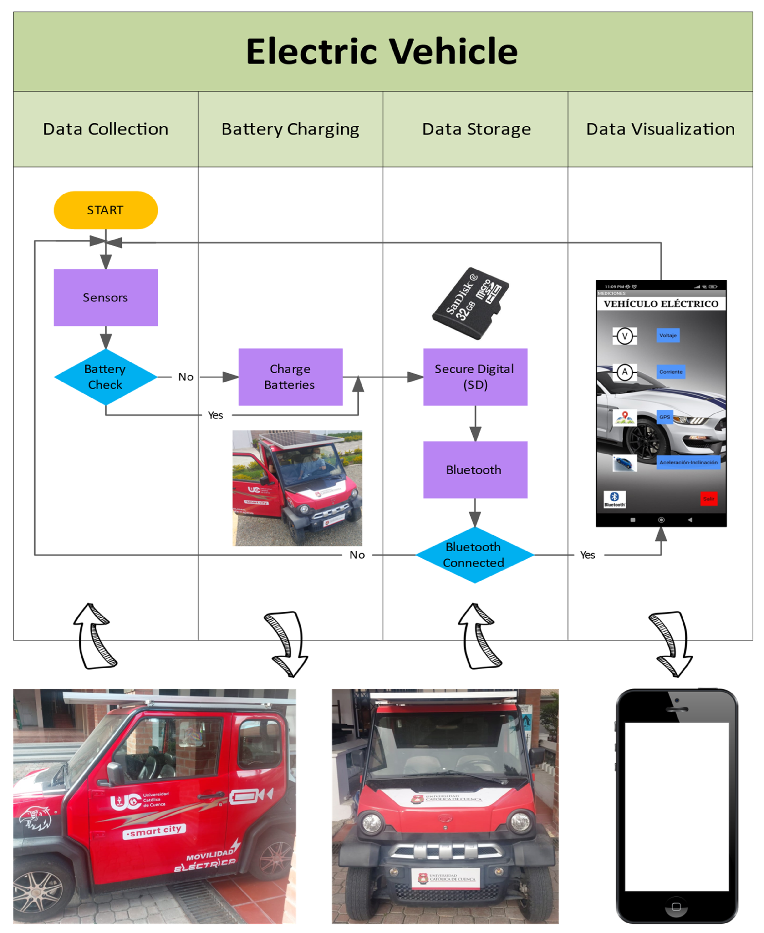
Figure 2 shows a flow diagram that illustrates the functioning of the developed program. The details of the four main stages are explained below.
  • Data collection: In this phase, as its name indicates, information on some physical variables is obtained using sensors. The sensors detect the battery voltage, current consumption, acceleration, and location.
  • Battery charging: At this stage, power is used from the 350 W PV, which is responsible for sending energy to each battery via a relay system through a programmed sequence. The charge cycle conditions are set based on the discharge level of each battery.
  • Data storage: At this stage, the information obtained from the sensors are saved in two ways:
    • SD module for Arduino: The data are programmatically stored in a .txt file on a microSD card;
    • Cellphone: Another way to save the data is on a cellphone via an app. The data are only saved if the cellphone is connected to the vehicle through Bluetooth. The information is also stored in a .txt file in the SD of the cell phone.
  • Data visualization: This stage is an add-on, as it is not essential for the functioning of the project. The data obtained by the sensors are visualized in an application created using App Inventor, which is connected via Bluetooth to the module in the EV for its operation. It allows the user to navigate through different screens to observe the data on the parameters.
The software design was also divided into two sections, related to the EV and the app.

2.3. Software Developed for the EV

The programming of the microcontroller was carried out in Arduino’s proprietary language (high-level programming processing), which is based on C/C++, to allow for quick programming without needing to enter the low-level programming of the controller.
The programming was modular, since this made it straightforward to modify the program (e.g., to include a new sensor using a function).
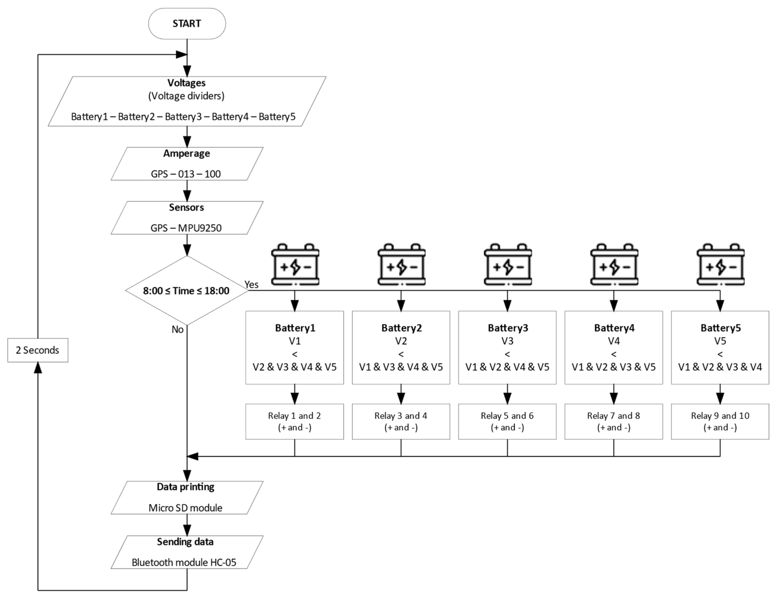
All data are processed internally in the microprocessor, as decisions are made based on operations. Data can be stored in two ways external to the microprocessor: as a file on a micro-SD card, or saved in a cellphone via Bluetooth communication with the application. This process of reading, processing, and saving data is shown in Figure 3.

2.4. Cellphone Application

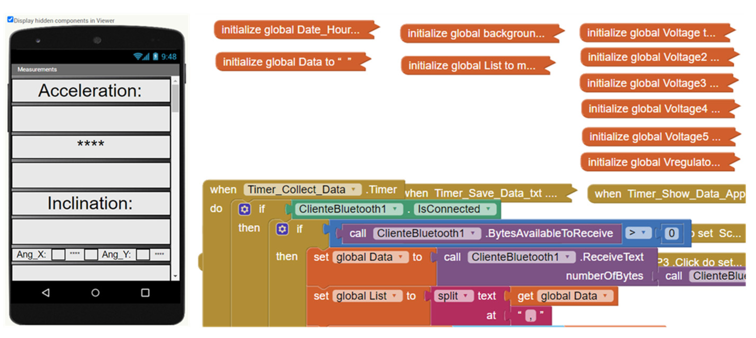
App Inventor is a web development tool in which simple and complex applications can be created via mobile devices. Using this software, a program was designed for viewing the information on the different parameters (sensors) installed in the EV.
The software has two stages, referred to as design and blocks. The design stage includes the configuration of all the parts that will be visible in the application and the second stage involves the programming of the blocks, as shown in Figure 4.
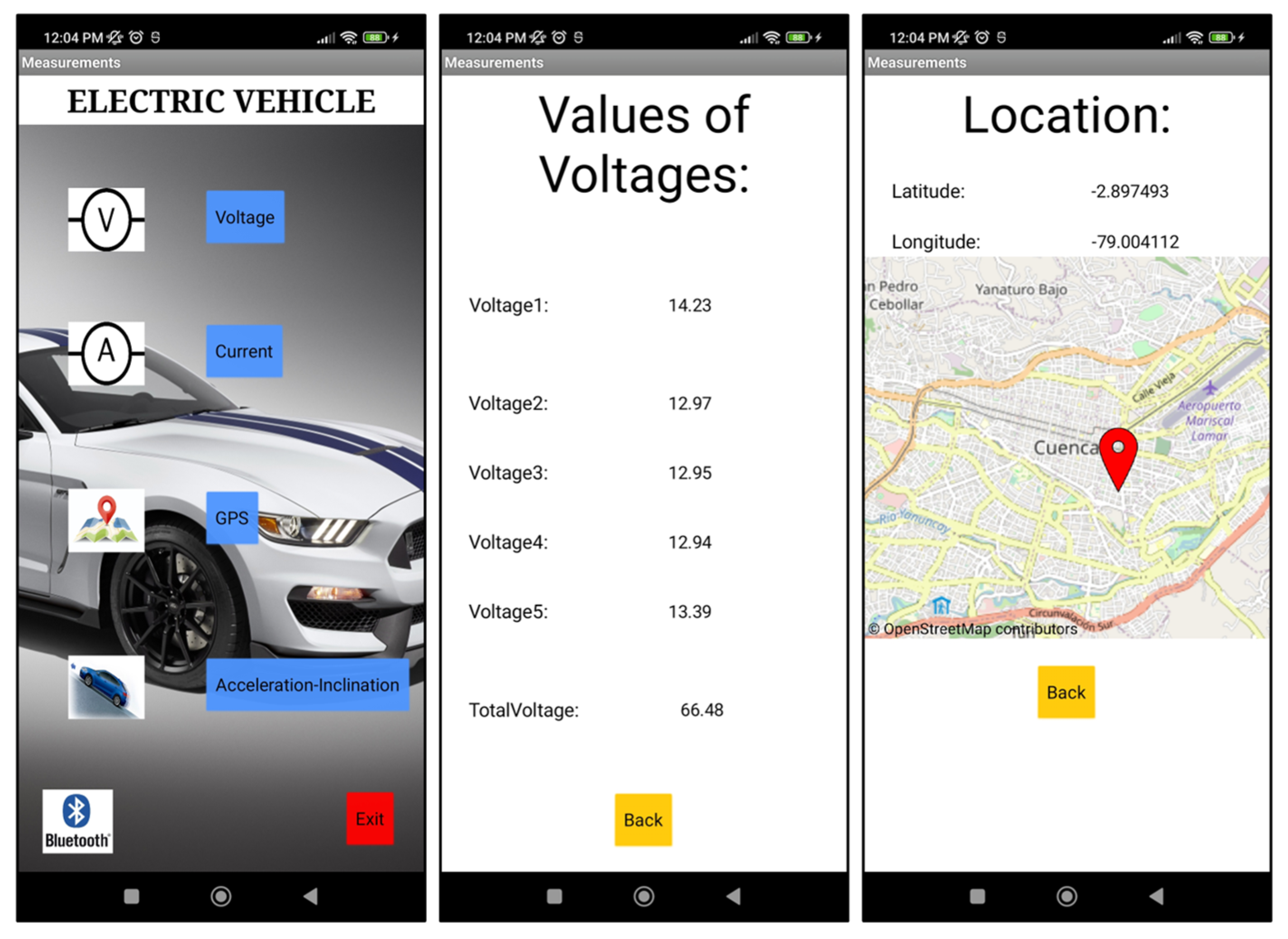
A Bluetooth module was added to the main board to send data to the mobile app. On the Android device where the app was installed, the EV parameters could be observed in real time. The app contains a menu with different screens for displaying the various parameters: the voltage, current, acceleration, inclination, and location, as shown in Figure 5.

2.5. Load Equalization System

The difference between the battery voltages increases with the number of charge and discharge cycles, which can lead to overcharging and over-discharging of some batteries. This is where the voltage equalizer comes into play, as it is fundamental in terms of improving the charging capacity and life cycle of the battery, as described in [25].
A grid-connected EV charges its five series-connected batteries evenly, regardless of which ones are more or less charged. The proposed system uses the analog inputs of the microcontroller to receive signals on the battery charge levels through a voltage divider in order to adapt the signal to the maximum voltage level supported by the ADC. The system checks a battery with a low charge level and connects the solar charging module to it; after 30 min, it again checks the voltage level of each battery and repeats the process of connecting the solar charging module to a new battery, and so on. This is carried out during the day, when it is possible to take advantage of sunlight, from 6:00 a.m. to 6:00 p.m. The details of the load equalization system can be seen in Figure 6.

3. Results

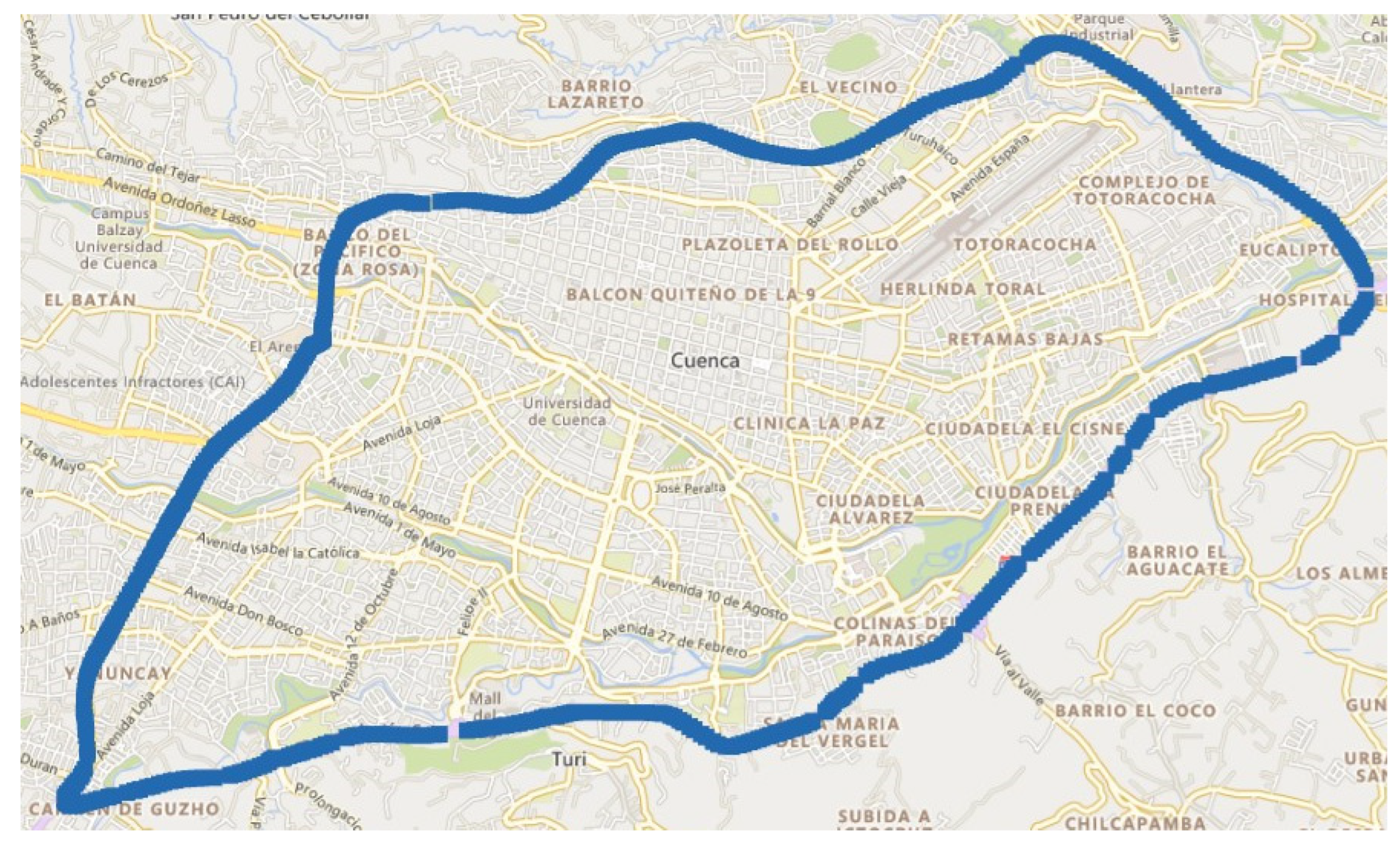
Tests were carried out on the EV to verify the performance of the system, subjecting it to the same routes with and without the PV. The route included a fast road (highway) and a low-speed road due to higher vehicular traffic to allow us to observe the behavior of the batteries. The route involved a total distance of 22.5 km.
The EV trajectories were calculated for three passengers, with an average weight of 80 kg each. It is essential to consider these data since this additional vehicle load affects the performance of the EV in terms of its speed, acceleration, braking, and consumption. The extra weight due to the PV was 22.80 kg. The details of the route can be seen in Figure 7.
The circuit covered by the EV consisted of two routes, one outbound and one return. The outbound route ran from the De Los Choferes gas station to the entrance to the parish of Baños via the Panamerican Highway. The return route ran from the entrance to the parish of Baños back to the De Los Choferes gas station via De Las Américas Avenue.
Some important data that should be considered are the radiation and temperature. Table 2 shows the meteorological information for the days on which the trajectories were tested.
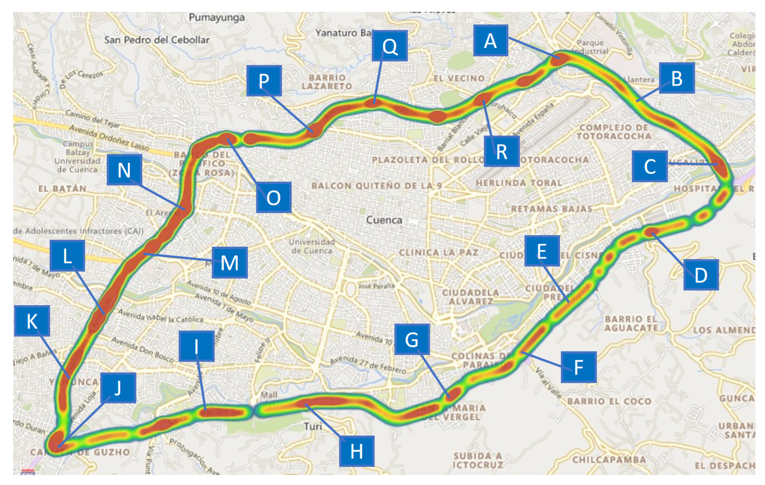
Figure 8 shows the sectors in which the EV stopped or moved slowly (short periods of movement) and indicates the areas where there was more traffic or sectors with greater inclination.
Table 3 summarizes the points shown in Figure 8 in terms of whether they represent a traffic zone or inclined zone.
Figure 9a,b show the parameters obtained over the EV trajectory without and with PV, respectively (battery voltage level, EV current consumption, EV speed, and track inclination). The figure also includes the points mentioned above; it is worth noting that most of these points corresponded to roundabouts or intersections with traffic lights.
A path analysis was performed to understand the behavior of the EV.
  • Section A–C. This path began at the De los Choferes gas station roundabout, as this is a road section with a fast vehicular flow. It can be seen from Figure 9a that the EV traveled at a high speed, causing the high energy consumption of the batteries. A high current is observed, and the battery voltage starts to decrease. Figure 9b shows similar behavior, except with a decrease in speed due to a single traffic light on the route. Similarly, at point C (the Y-intersection of the Hospital del Rio sector), there is a decrease in speed and intensity due to an increase in traffic flow in this area until the Cuenca–Azogues–Biblián expressway is reached.
  • Section D–G. This section begins at the IESS roundabout (where there is little traffic as it is a high-speed road). There is fast vehicular flow at points E and F, so there is an increase in speed and intensity that are almost constant throughout the trajectory until the Mollobamba roundabout is reached, where there is an evident decrease in the speed of the EV.
  • Section H–J. From the Camino a Turi roundabout, a decrease in average speed can be observed due to the increase in vehicular traffic in this area. After point I, there is a road with a negative inclination, and at the same time, it undergoes a broad division into Diego de Tapia Street, so there are no traffic problems. It can therefore be seen from Figure 9 that the speed and intensity of the EV are higher. At point J, there is an increase in vehicular flow at the traffic interchange, so the speed and intensity values decrease.
  • Section K–R. After leaving the interchange and between De las Américas Avenue and the De los Choferes Gas Station Roundabout, the trajectory becomes slow because this avenue has several traffic lights and is within a populated area of the city where the tramway runs. This generates an increase in traffic, and it can be clearly seen from Figure 8 that there are increases and decreases in speed and intensity over this road section.
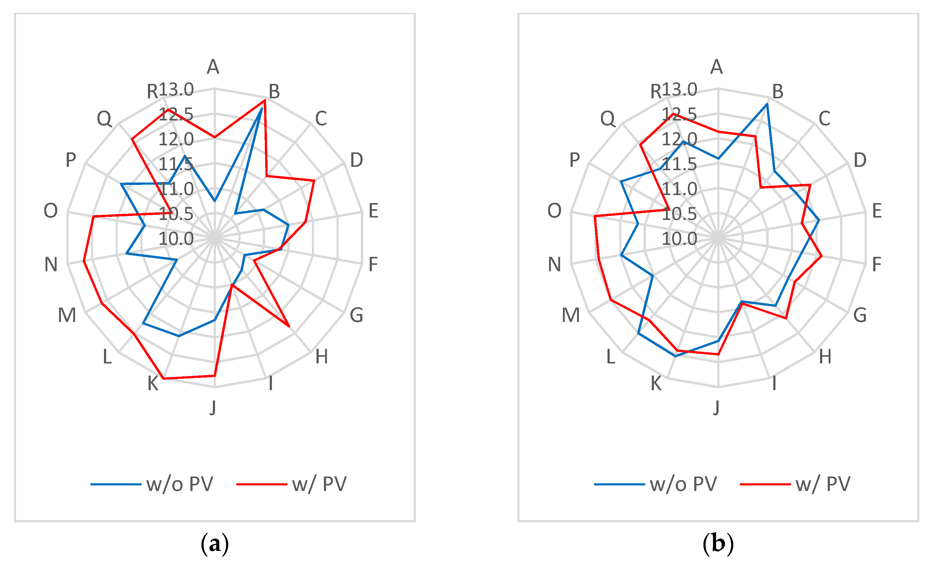
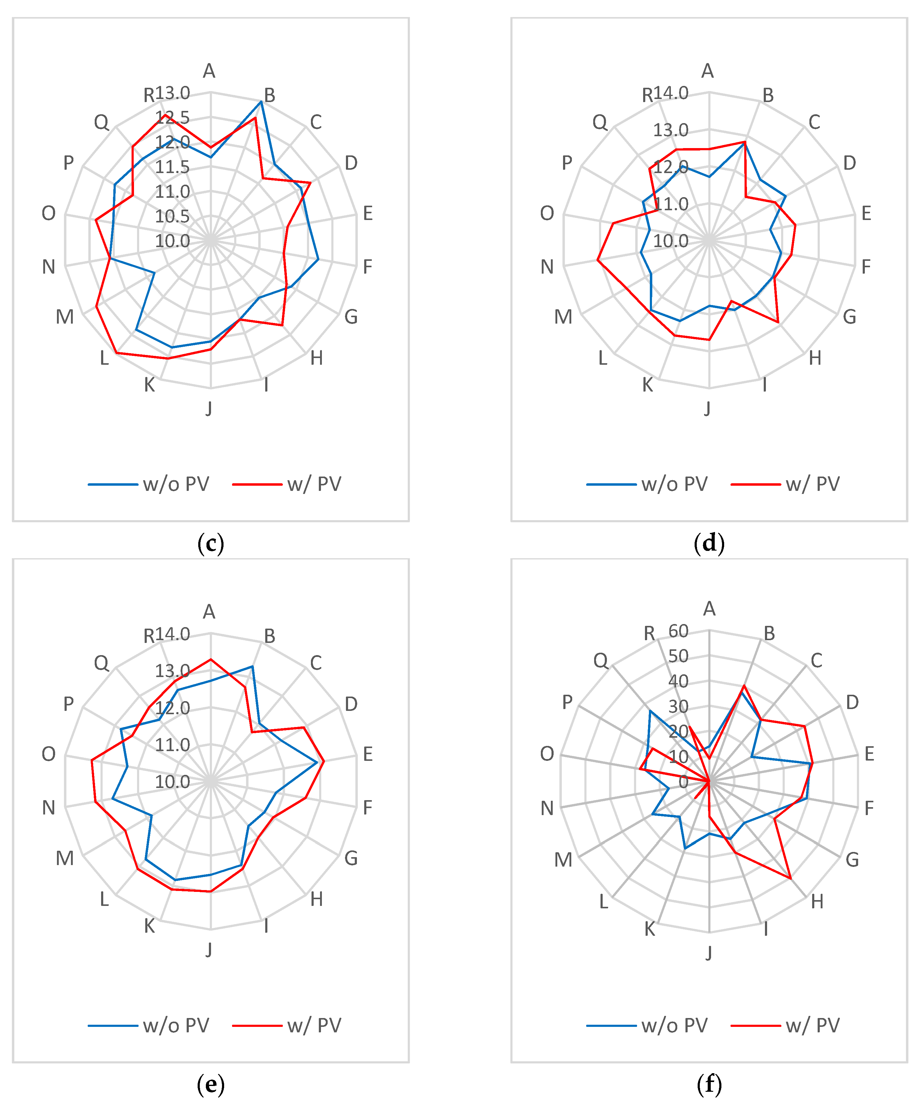
Figure 10 below shows a comparison of the data in the form of radial plots, making it possible to differentiate better between the behavior of the batteries at the different trajectory points for the EVs with and without the charging system. In addition, it can be seen that there is a more significant contribution from the PV in the J–O section, corresponding to heavy traffic and a signalized zone. However, no two routes will be the same, since the traffic conditions, speed Figure 10f, and traffic light stops, among others, will vary, and these differences in the measured data must be considered. Figure 10b–e show the data for the other batteries; an improvement in their voltages can be observed since the charge was higher for batteries 1, 4, and 5.
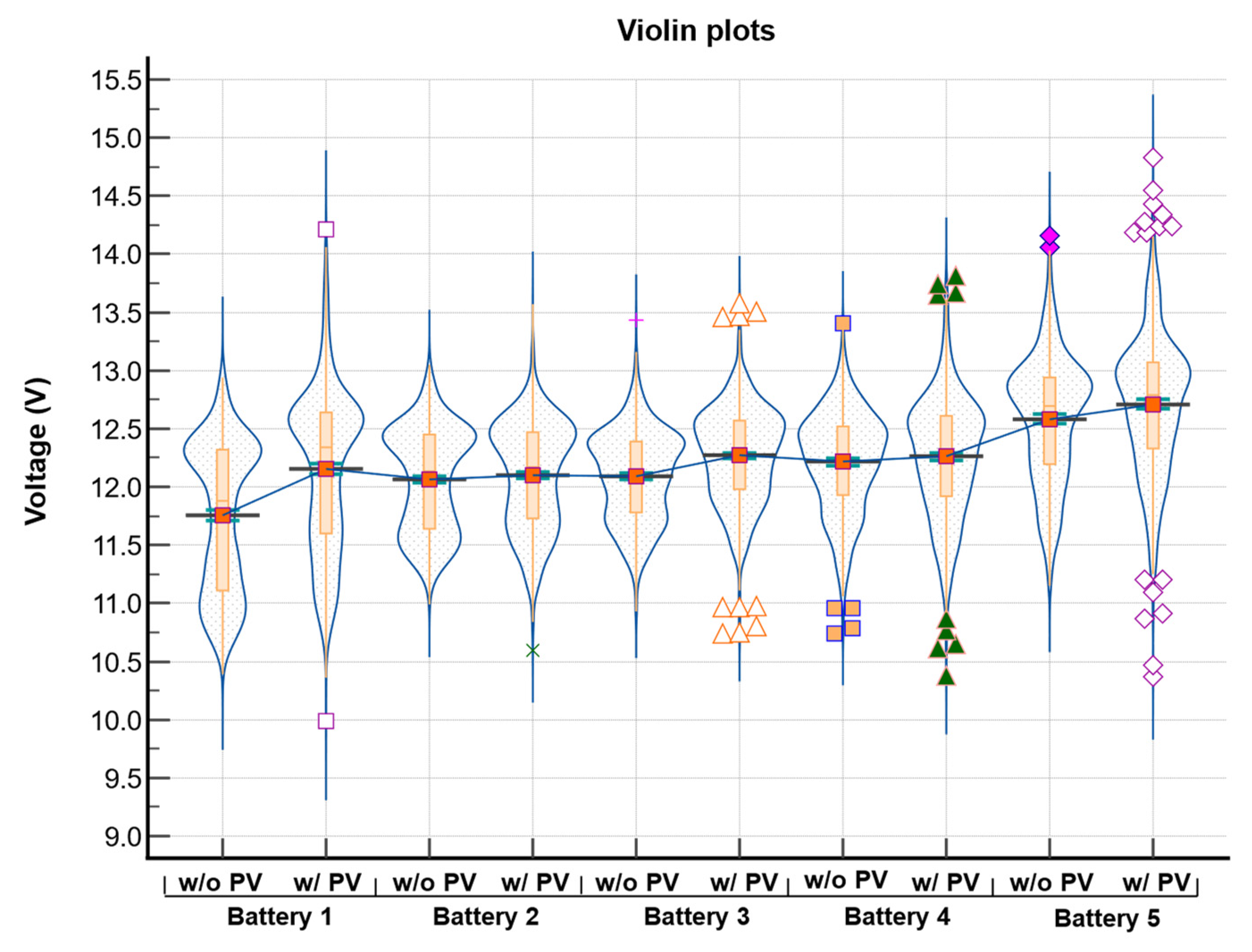
Figure 11 presents violin plots of the distribution of the data, which show the relationship between the battery voltage data for the runs with and without PV. Table 4 summarizes the values obtained from the violin diagrams. The main difference is observed for battery 1, where the data density (measured voltages) is higher for the run with PV. For batteries 2, 3, and 4, the results are similar but with small differences. Similarly, the data are very similar for battery 5 except that the data density (measured voltages) shows a higher voltage. This is due to the fact that the batteries that are closer to the negative pole undergo greater discharge.
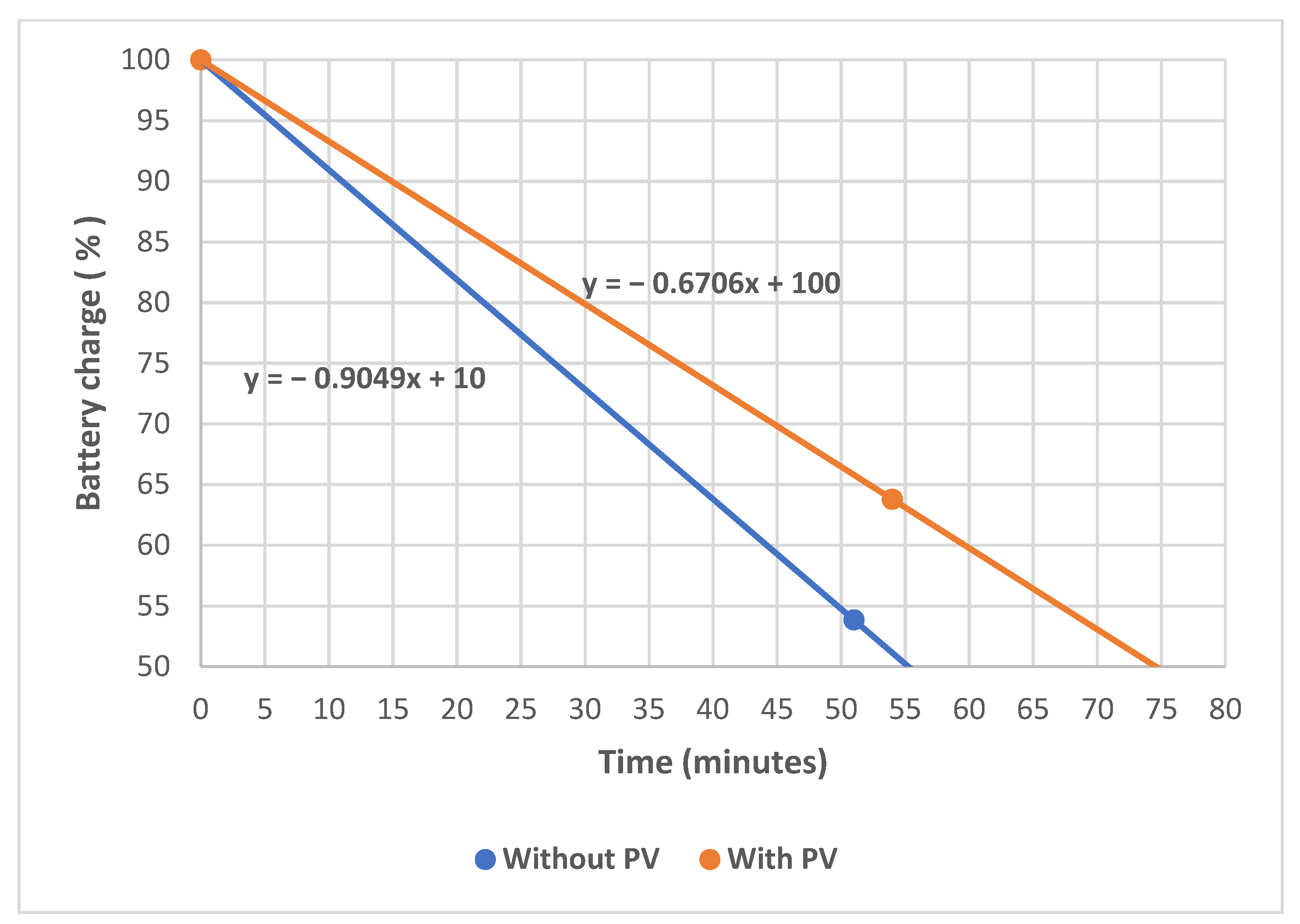
Figure 12 shows the discharge slopes for the batteries for both tests of the electric vehicle (with and without PV). A comparison of the vehicle’s range shows that the orange line has a lower slope than the blue line; this difference represents a 27.9% improvement in the performance of the vehicle.

4. Discussion

Our approach, which involved a charge equalization system and a 350 W PV, improved the efficiency of a Chock S2 EV by 27.9% in terms of its range of autonomous operation.
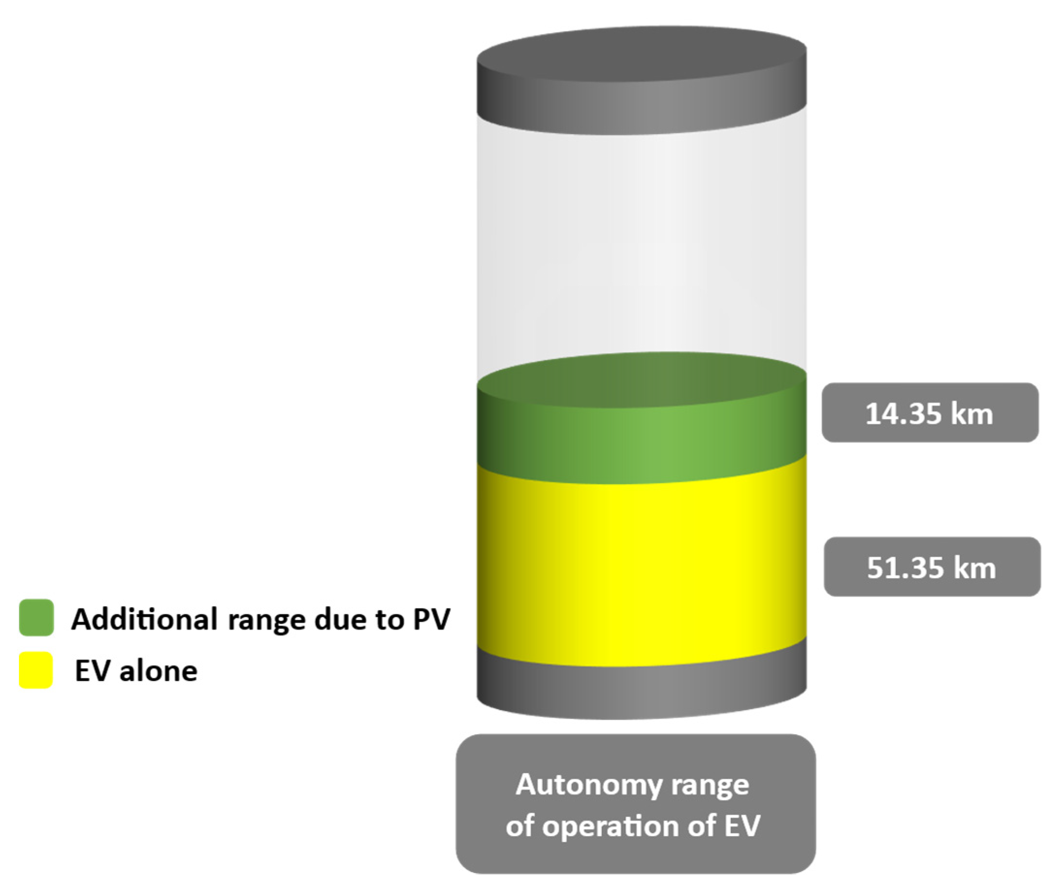
Figure 13 shows the increase obtained in the route taken by the EV. Our current data indicate that the vehicle has an operation range of 51.35 km, which can be increased to 65.69 km with the addition of PV.
From similar research conducted by Reinoso and Ortega [27] on the same EV (Dayang Chock S2), it can be observed that the use of PV also improves the efficiency of the EV from 16% to 33% depending on the variation in solar radiation. However, deep discharges were used in this study, which are not recommended since they reduce the range of the autonomous operation of the car and damage the life span of the batteries.
In addition, our results corroborate research by Mohamed, Aymen, Altamimi, Khan, and Lassaad [28], who reported that the contribution of PV to the batteries depends on the speed of the EV: the higher the speed, the lower the contribution of PV to the batteries. If the vehicle is parked or at a standstill, the contribution from PV is 100%. That means that if the EV is used by the owner to go to work, the batteries can be charged while it is parked, without the need for a connection to the local power grid; this benefits the user, since over the working day (usually 8 h), the PV panel will provide all the energy needed for charging.
Similarly, Amin, Budiman, Kaleg, Sudirja, and Hapid [29] presented a prototype of an active battery charge balancing system for EVs based on a cell charger. The objective was to increase the useful energy of a 15S1P 200 Ah LiFePO4 battery pack with energy taken directly from the power grid. Their test results indicated that the time required to equalize the voltage of the 15 batteries was 6 h on average. A monitoring system was installed to protect them from possible underloading and overloading by measuring the voltage of each cell through a microcontroller. If the cell voltage was abnormal, a power circuit formed of SSRs was responsible for selecting the specific cell to be balanced. Using a similar methodology for battery charging management, we achieved a significant improvement by integrating renewable (PV) energy into the EV, which enables continuous charging of the EV as long as solar irradiation is available. The user need not depend entirely on the grid supply to maintain a balance in the state of charge of the batteries as the energy produced by the PV is managed efficiently during the day, thereby avoiding deep discharges in the batteries, which reduce their life span. In addition, a pathway has been established for future tests and improvements of the proposed system within Cuenca, Ecuador. Table 5 compares the performance achieved by our approach with previous works in this area.

5. Conclusions

Based on the results presented here, we can observe that using VIPV with a load equalizer system can increase the performance of an EV more than when PV is used alone. Naturally, this improvement will vary depending on the solar radiation along the route. Research is therefore planned for different routes at different times of the year to evaluate the increase in the EVs autonomous range more accurately. In addition, factors such as the vehicular traffic and road inclination affect the autonomous range of an EV; another research project is therefore being carried out in Cuenca, an Andean city with a topography involving different slopes. In addition, it is essential to consider the hours of vehicular traffic for which a study will be conducted.
In the future, the proposed system could be improved, and the efficiency could be increased by using higher-power PVs. However, this would lead to switching and changes in the connection systems, as these would need to be improved to support the power provided by PV; an obvious example would be the use of SSRs.
The efficiency of the current PV is 17.95%, its power rating is 350 W, and its dimensions are 1.95 × 0.99 m. This panel could be replaced by one with a higher efficiency. Currently, panels with efficiencies of approximately 22% and power ratings of more than 535 W are already available on the Ecuadorian market. For PV with split-cell technology, its dimensions in m2 do not exceed the physical dimensions of current panels by 25%. This would give an improvement in efficiency and energy performance, as it is known that split-cell PVs are partially affected by shade; therefore, the production loss would be slight.

Author Contributions

Conceptualization, D.-A.A.-A., B.-H.C.-C., J.-F.S.-M. and J.-C.C.-T.; data curation, D.-A.A.-A., B.-H.C.-C., J.-F.S.-M. and J.-C.C.-T.; formal analysis, J.-C.C.-T.; funding acquisition, J.-C.C.-T.; investigation, D.-A.A.-A., B.-H.C.-C., J.-F.S.-M. and J.-C.C.-T.; methodology, D.-A.A.-A., B.-H.C.-C., J.-F.S.-M. and J.-C.C.-T.; project administration, J.-C.C.-T.; resources, J.-C.C.-T.; software, D.-A.A.-A., B.-H.C.-C., J.-F.S.-M. and J.-C.C.-T.; supervision, J.-C.C.-T.; writing—original draft, D.-A.A.-A., B.-H.C.-C. and J.-F.S.-M.; writing—review and editing, D.-A.A.-A. and J.-C.C.-T. All authors have read and agreed to the published version of the manuscript.

Funding

This research received no external funding.

Data Availability Statement

Not applicable.

Acknowledgments

This research was undertaken as part of the work of the research group “Sistemas Embebidos y Visión Artificial en Ciencias Arquitectónicas, Agropuecuarias, Ambientales y Automática (SEVA4CA)” under a project entitled “Mapeo de la Calidad del aire a nivel paranasal mediante IoT”.

Conflicts of Interest

The authors declare no conflict of interest.

References

  1. Banco Mundial. Desarrollo Urbano: Panorama General. Available online: https://www.bancomundial.org/es/topic/urbandevelopment/overview#:~:text=Enelmundo%2Cmásdel,crecimientoyproporcionarserviciosbásicos (accessed on 28 November 2021).
  2. Lazaroiu, G.C.; Roscia, M. Definition Methodology for the Smart Cities Model. Energy 2012, 47, 326–332. [Google Scholar] [CrossRef]
  3. Silva-Castaño, F. Conducción, En Condiciones Reales de Galicia, de Un Vehículo Eléctrico Con Autonomía Extendida (REX). Dínamo Técnica 2016, 19, 1–4. [Google Scholar]
  4. Saavedra-Moreira, R.-I. Diagnóstico de Transporte Inteligente Para La Ciudad de Guayaquil. Ph.D. Thesis, Universidad Internacional del Ecuador, Quito, Ecuador, 2021. [Google Scholar]
  5. Kasprzyk, L. Modelling and Analysis of Dynamic States of the Lead-Acid Batteries in Electric Vehicles. Eksploat. Niezawodn. 2017, 19, 229–236. [Google Scholar] [CrossRef]
  6. Mendoza-Varela, I.A.; Alvarez-Diazcomas, A.; Martinez-Prado, M.A.; Rodriguez-Resendiz, J. Modeling and Control of a Phase-Shifted Full-Bridge Converter for a LiFePO4 Battery Charger. Electronics 2021, 10, 2568. [Google Scholar] [CrossRef]
  7. López-Redondo, N. Comparando Las Emisiones de Los Vehículos de Combustión y Los Eléctricos: ¿cuál Es Realmente Menos Contaminante? Available online: https://movilidadelectrica.com/emisiones-gasolina-electrico-cual-emite-menos/ (accessed on 28 November 2021).
  8. Ota, Y.; Araki, K.; Nagaoka, A.; Nishioka, K. Facilitating Vehicle-Integrated Photovoltaics by Considering the Radius of Curvature of the Roof Surface for Solar Cell Coverage. Clean. Eng. Technol. 2022, 7, 100446. [Google Scholar] [CrossRef]
  9. Sinuraya, A.; Sinaga, D.H.; Simamora, Y.; Wahyudi, R. Solar Photovoltaic Application for Electric Vehicle Battery Charging. J. Phys. Conf. Ser. 2022, 2193, 12075. [Google Scholar] [CrossRef]
  10. Yu, F.; Zhu, Z.; Liu, X.; Zhang, Z. Electric-Drive-Reconstructed Onboard Charger for Solar-Powered Electric Vehicles Incorporating Six-Phase Machine. IEEE Trans. Power Electron. 2022, 37, 6544–6555. [Google Scholar] [CrossRef]
  11. Srivastava, S.; Karthikeyan, S.; Arumugam, P.; Kumar, A.; Thanigaivel, G. Design, Development and Experimental Investigation on the Effect of HVAC Power Consumption in Electric Vehicle Integrated with Thin Film Solar PV Panels; SAE Technical Papers; SAE International: Warrendale, PA, USA, 2021. [Google Scholar] [CrossRef]
  12. Mil’shtein, S.; Zinaddinov, M.; Asthana, D.N.; Scheminger, J. Design and Testing of Solar/Electric Cart. J. Phys. Conf. Ser. 2021, 1921, 12021. [Google Scholar] [CrossRef]
  13. Masuda, T.; Araki, K.; Okumura, K.; Urabe, S.; Kudo, Y.; Kimura, K.; Nakado, T.; Sato, A.; Yamaguchi, M. Next Environment-Friendly Cars: Application of Solar Power as Automobile Energy Source. In Proceedings of the 2016 IEEE 43rd Photovoltaic Specialists Conference (PVSC), Portland, OR, USA, 5–10 June 2016; pp. 580–584. [Google Scholar]
  14. Sekhar, G.C.; Krishna, D.G.; Abhimanue, H.; Meeran, F.K.; Janardhanan, S. Shape Improvisation of the Solar Panels on the Roof of an Electric Vehicle. J. Inst. Eng. (India) Ser. C 2021, 102, 1041–1050. [Google Scholar] [CrossRef]
  15. Alvarez-Diazcomas, A.; López, H.; Carrillo-Serrano, R.V.; Rodríguez-Reséndiz, J.; Vázquez, N.; Herrera-Ruiz, G. A Novel Integrated Topology to Interface Electric Vehicles and Renewable Energies with the Grid. Energies 2019, 12, 4091. [Google Scholar] [CrossRef] [Green Version]
  16. Alvarez-Diazcomas, A.; Rodríguez-Reséndiz, J.; Carrillo-Serrano, R.V. An Improved Battery Equalizer with Reduced Number of Components Applied to Electric Vehicles. Batteries 2023, 9, 65. [Google Scholar] [CrossRef]
  17. Alvarez-Diazcomas, A.; Estévez-Bén, A.A.; Rodríguez-Reséndiz, J.; Martínez-Prado, M.A.; Carrillo-Serrano, R.V.; Thenozhi, S. A Review of Battery Equalizer Circuits for Electric Vehicle Applications. Energies 2020, 13, 5688. [Google Scholar] [CrossRef]
  18. Quraan, M.; Yeo, T.; Tricoli, P. Design and Control of Modular Multilevel Converters for Battery Electric Vehicles. IEEE Trans. Power Electron. 2016, 31, 507–517. [Google Scholar] [CrossRef]
  19. Yamaguchi, M.; Masuda, T.; Nakado, T.; Zushi, Y.; Araki, K.; Takamoto, T.; Okumura, K.; Satou, A.; Yamada, K.; Ota, Y. Importance of Developing Photovoltaics-Powered Vehicles. Energy Power Eng. 2021, 13, 147–162. [Google Scholar] [CrossRef]
  20. Villanueva-Gutiérrez, L. Implementación de Un Sistema Fotovoltaico En Un Vehículo Eléctrico Para La Carga de Batería. Grade Thesis, Pontificia Universidad Católica de Chile, Santiago de Chile, Chile, 2009. [Google Scholar]
  21. Consejo Nacional de Electricidad (CONELEC) Plan de Electrificación 2013–2022. Available online: https://www.ariae.org/servicio-documental/plan-de-electrificacion-2013-2022#:~:text=ElPlanMaestrodeElectrificación,%2Cregularidad%2Ccontinuidadycalidad (accessed on 7 April 2022).
  22. Delgado-Orellana, G.; Orellana-Samaniego, M. Estimación de La Radiación Solar Global Diaria En El Cantón Cuenca Mediante La Aplicación Del Modelo Bristow & Campbell. Bachelor’s Thesis, Universidad Politécnica Salesiana, Cuenca, Ecuador, 2015. [Google Scholar]
  23. Kaiying Power Supply & Electrical Equip Co., Ltd. Batería de Ciclo Profundo 6-Evf-150 Batería Para Coche de Golf de La Batería de Plomo Ácido/Batería VRLA Batería Eléctrica. Available online: https://es.made-in-china.com/co_longwaybattery/product_Deep-Cycle-Battery-6-Evf-150-Battery-for-Golf-Car-Lead-Acid-Battery-VRLA-Battery-Electric-Battery_hrnonehyu.html (accessed on 29 October 2022).
  24. Xupai Power Co., Ltd. 6-EVF-150 Electric Golf Car Battery Pack 12 V 150 AH. Available online: https://www.alibaba.com/product-detail/6-EVF-150-Electric-Golf-Car_60462967801.html (accessed on 12 January 2023).
  25. Dam, S.K.; John, V. Low-Frequency Selection Switch Based Cell-to-Cell Battery Voltage Equalizer with Reduced Switch Count. IEEE Trans. Ind. Appl. 2021, 57, 3842–3851. [Google Scholar] [CrossRef]
  26. NASA. POWER NASA Prediction of Worldwide Energy Resources. Available online: https://power.larc.nasa.gov/data-access-viewer/ (accessed on 18 March 2023).
  27. Reinoso, L.; Ortega, J. Incremento de La Autonomía de Un Vehículo Eléctrico Dayang CHOK-S Mediante Paneles Solares. Rev. Digit. Novasinergia 2020, 3, 40–46. [Google Scholar]
  28. Mohamed, N.; Aymen, F.; Altamimi, A.; Khan, Z.A.; Lassaad, S. Power Management and Control of a Hybrid Electric Vehicle Based on Photovoltaic, Fuel Cells, and Battery Energy Sources. Sustainability 2022, 14, 2551. [Google Scholar] [CrossRef]
  29. Amin, A.; Budiman, A.C.; Kaleg, S.; Sudirja, S.; Hapid, A. Active Battery Balancing System for Electric Vehicles Based on Cell Charger. Int. J. Power Electron. Drive Syst. 2021, 12, 1729. [Google Scholar]
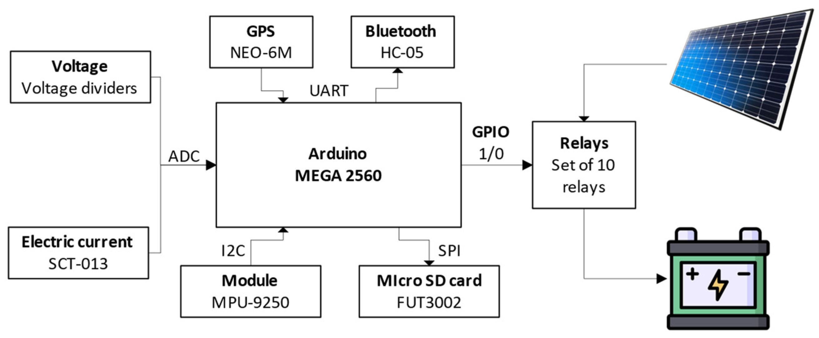
Figure 1. Hardware architecture developed for the EV.
Energies 16 03360 g001
Figure 2. Flow diagram showing the basic operation of the system (hardware and software).
Energies 16 03360 g002
Figure 3. Flowchart showing data collection and storage.
Energies 16 03360 g003
Figure 4. The App Inventor application, showing the graphic display and block programming.
Energies 16 03360 g004
Figure 5. Screenshots of the application created in App Inventor, showing the navigation screens.
Energies 16 03360 g005
Figure 6. Schematic diagram of the load equalizer.
Energies 16 03360 g006
Figure 7. Trajectory used to test the EV.
Energies 16 03360 g007
Figure 8. Map with selected points for analysis (A–R points explained in Table 3).
Energies 16 03360 g008
Figure 9. Data obtained for the EV trajectory: (a) without PV; (b) with PV.
Energies 16 03360 g009
Figure 10. Comparison of measurements at the analyzed points: (a) battery voltage 1; (b) battery voltage 2; (c) battery voltage 3; (d) battery voltage 4; (e) battery voltage 5; (f) EV speed; (A–R points explained in Table 3).
Energies 16 03360 g010aEnergies 16 03360 g010b
Figure 11. Data on each battery for runs with PV (w/) and without (w/o), (Symbols represent battery voltage outliers).
Energies 16 03360 g011
Figure 12. Battery discharge slopes for EVs with and without PV.
Energies 16 03360 g012
Figure 13. Increase in the range of a Chock S2 EV.
Energies 16 03360 g013
Table 1. Description of components.
Electrical ComponentDescription
Arduino Mega 2560This microcontroller is one of the most versatile of the Arduino family, due to its high number of digital and analogue pins.
SCT-013One of the advantages of this sensor is that it can measure AC current without interrupting (cutting) the cable.
GPS-neo-6mThis is a receiver module for any application requiring geolocation. It has a powerful antenna and is compatible with most microprocessors.
Bluetooth HC-05This module is compatible with any wireless device on the market.
MPU-9250This module offers three functionalities: gyroscope, magnetometer, and accelerometer, the last of which is necessary to calculate the degrees of inclination of the EV.
SD Card FUT302This device is required for data storage.
Table 2. Temperature and radiation parameters (commuting days).
DayHourAverage Temperature (°C)Maximum Temperature (°C)Minimum Temperature (°C)Irradiance
(kW-h/m2)
8 December 202115:4715.122.19.73.64
16:363.48
15 December 202113:3715.821.1133.34
14:313.31
Note: Irradiance rates obtained from NASA POWER [26].
Table 3. Details of the different points (location, situation, construction height, track width).
DateHourLocationSituationConstruction HeightTrack Width (m)Description
PointZoneInclinationTraffic or Traffic LightsCirculation
8 December 202115:47:25ADe las Américas Avenue X H111Intersection of De las Américas Avenue and Rio Machángara Street De Los Choferes gas station roundabout
15:47:25BDe las Américas Avenue XH126Las Américas Ave., in front of the Metales y Metales store
15:51:58CDe las Américas Avenue X H230Intersection of Americas Avenue and Gonzalez Suarez Avenue; Y-intersection of the Hospital del Rio sector
15:54:11DCuenca–Azogues–Biblián expressway X H247Intersection of the Cuenca–Azogues–Biblián expressway and the road to Rayoloma, IESS roundabout
15:56:17ECuenca–Azogues–Biblián expressway XH130Panamerican Highway, perpendicular to Restrepo brothers
15:57:48FCuenca–Azogues–Biblián expressway XH124Traffic distributor Camino del Valle
15:59:43GCuenca–Azogues–Biblián expressway X H142Mollobamba roundabout
16:03:24HCuenca–Azogues–Biblián expressway X H142Camino a Turi roundabout
16:05:33ICuenca–Azogues–Biblián expresswayX H226Panamerican Highway and Diego de Tapia
16:09:07JCuenca–Azogues–Biblián expressway X H18Panamerican Highway and De las Americas Avenue, at the overpass
16:11:27KDe las Américas Avenue X H227In front of the Coral Hipermercados supermarket
16:14:22LDe las Américas Avenue X H127Intersection of Luis Moscoso and De las Américas Ave
16:18:16MDe las Américas Avenue X H227In front of Dragon Park
16:21:11NDe las Américas Avenue X H225De las Américas Avenue and Remigio Crespo Avenue, in front of El Arenal Market
16:25:30ODe las Américas Avenue X H227De las Americas Ave. and Miguel Cabello Balboa
16:27:29PDe las Américas Avenue X H132Intersection of Héroes de Verdeloma Avenue and De las Américas Avenue, De las Américas Park sector
16:30:38QDe las Américas Avenue X H129Intersection of Luis Cordero and De las Americas Ave.
16:33:23RDe las Américas Avenue X H239Miraflores roundabout, park sector
H1 < 10 mH2 ≥ 10 m o < 30H3 ≥ 30 m
Table 4. Statistical data for each battery with PV (w/) and without (w/o).
Data Comparison
Battery NumberData TypeLowest ValueHighest ValueMedian25th Percentile75th Percentile
1Data w/o PV10.3912.9411.8811.1112.32
Data w/ PV9.9914.2112.3411.6012.64
2Data w/o PV10.9913.0512.1311.6412.45
Data w/ PV10.613.5712.1711.7312.47
3Data w/o PV10.9313.4312.1311.7812.39
Data w/ PV10.7413.5812.3211.9812.57
4Data w/o PV10.7413.4112.2811.9312.52
Data w/ PV10.3813.8112.3211.9212.61
5Data w/o PV11.1514.1612.6912.1912.94
Data w/ PV10.3714.8312.7912.3313.07
Table 5. Improvements obtained by our approach compared to similar schemes.
Similar SchemesImprovements in Our Approach
The authors presented a battery charging system using four 100 W monocrystalline PVs to supply power to an EV with a 1 kW motor; this provided an additional range of 1.2 h when the system was fully charged [9].We realized a charge equalizer system with a 350 W panel, which improved the vehicle’s range by 27.9%.
Using an EV running at 48 V, the authors installed thin-film PVs on the roof with the aim of meeting the power demand of the air-conditioning system [11].Our system was designed to meet the global energy demand of the entire vehicle.
The authors designed and ran tests on a lightweight four-wheel drive EV. The car could carry four passengers and an additional attached load of about 500 kg. It had a battery pack with LiFePO4 cells with an output of 6000 W. A 600 W PV was installed on the roof, which provided constant recharging for the lithium-ion batteries [12].Although our vehicle did not have the same characteristics, an increase in operational range was realized with a 350 W panel, and a charge equalizer was designed and developed.
In similar research carried out on the same EV (Dayang Chock S2), it was observed that the use of PV also improved the autonomous range of the EV between 16% and 33% depending on the variation in solar radiation [27]. However, in this study, deep discharges were carried out, which is not recommended, as they reduce the autonomous range of the car and damage the useful life of the batteries.Our results were achieved without carrying out deep discharge tests on the batteries, as these can damage their useful life. In addition, analysis and monitoring of the batteries were carried out.
Disclaimer/Publisher’s Note: The statements, opinions and data contained in all publications are solely those of the individual author(s) and contributor(s) and not of MDPI and/or the editor(s). MDPI and/or the editor(s) disclaim responsibility for any injury to people or property resulting from any ideas, methods, instructions or products referred to in the content.