1. Introduction
The degree of wear of injection apparatus in compression-ignition engines significantly affects the emission of toxic substances in exhaust gases. Modern diesel engines are equipped with a Common Rail system, which consists of two systems: low and high pressure. The task of the low-pressure system is to supply filtered fuel to the high-pressure section of the injection pump. The high-pressure system begins in the pumping sections of the injection pump, which is responsible for creating pressure by accumulating fuel in the system. The high-pressure system consists of an injection pump, high pressure tubing, fuel distribution rail, pressure regulator and pressure sensor, and fuel injectors. Unlike conventional systems, in Common Rail systems, the fuel injector is responsible for the amount of fuel injection into the engine’s combustion chamber, and the injection pump only generates pressure. The working parameters of the injection pump are the fuel outputs and the injectors: the injection dose and the overflow dose. The fuel is fed to the high-pressure section and then piled up through the pistons. In injection pumps, the most critical areas are the precision pairs on the section pistons, the surface of the bearing driving the sections in combination with the high-pressure discs. The fuel has a lubricating function in this space; therefore, the reduction of the friction coefficient has a significant impact on the durability of the injection pump and injector. The Common Rail system fuel injector can be divided into areas of the fuel atomizer chamber and the chamber controlling its operation. The working parameters of the fuel injectors responsible for the engine operation are injection and overflow doses. The fuel injector is an element installed in the engine head, and its tip in the engine’s combustion chamber and is responsible for the appropriate atomization of the set fuel value. Its operating conditions such as variable high pressures and ambient temperatures are extreme. Additional requirements regarding the quality of work (appropriate injection dose and precision of atomization) mean that the implementation of fuel injectors must be perfect. Precision pairs on the needle and control valve piston are responsible for the injector tightness. The fit tolerance of these elements is measured in micrometers. The consumption of these areas directly affects the overflow doses, which translates into the amount of fuel injected into the combustion chamber. The consumption of precision vapors is affected by fuel that lubricates it and discharges temperature. The physical parameters of fuels and their quality contribute to the wear and tear of the injection apparatus components.
Previously the impact of biofuels on the operation of a compression-ignition engine [
1,
2] or on the durability of injection apparatus was described [
3,
4], but a direct study of the operating parameters of the injection pump and fuel injectors is an innovative concept. This test consists of checking the injection pump and injector expense both on diesel and vegetable fuel. Biofuel has different physical properties [
5,
6] than diesel oil; therefore, the operating parameters of the apparatus components should be analyzed on the test bench. The authors [
1] present the impact of pure B100 biofuel on selected components of a compression ignition engine. The fuel tested was palm oil. The engine worked on it for 800 h at a high load and low speed around 1000 RPM. The engine oil was changed every 100 h, then its properties were tested in the laboratory. The results of the analysis showed that engine oil was consumed faster when using vegetable fuel, it was more diluted by impurities including water, the additives it contained were degraded, and the oil film decreased, which contributed to faster wear of engine components. Engine oil samples showed particles below 8 μm of elements such as Fe, Pb, Cu, Sn, Al, and Cr, which affected the wear rate of engine components. Increased content of silicone and deposits was also noticeable in the engine oil after 100 h of operation. In addition, after every 430 h of operation, it was necessary to clean the oil filter due to the content of water, silicone, and various deposits. After 100 h and the next 700 h of operation, the engine was dismantled for inspection (evaluation) purposes. The analysis showed contamination of engine components such as the head, pistons, valves, and fuel injectors, which were the same as for conventional fuel. The conclusions were that it is possible to use vegetable fuel as an alternative, but filters and engine oil should be changed more often. In addition, high-quality lubricating oils should be used with a higher content of water-absorbing additives and improving the lubrication factor. As can be seen, fuel additives play an important role in the operation process of an internal combustion engine, which causes anti-wear effects described in the paper [
2].
2. Wear of Injection System Elements on the Work of a Modern CI Engine
As a result of stricter ecological standards, sulfur and its compounds were removed from fuels. Sulfur, due to its lubricating properties, is a very good additive that reduces the friction of cooperating elements [
3]. Lower sulfur content in fuels reduced their lubricating properties. Research conducted by the authors of [
2] has shown that a very good substitute for sulfur compounds is fuels of vegetable origin due to the content of free glycerin, antioxidants, and phospholipids. However, it was pointed out in [
4] that the use of vegetable-derived fuel showed better lubricating properties than conventional fuel in the short term, but these properties deteriorated in the long run. This is due to the higher hygroscopicity of biofuels. In addition, alcohol added to vegetable fuels accelerates the corrosion processes of injection equipment components, which accelerates their consumption, therefore, anti-corrosive additives should be added to alternative fuels. Considerations regarding the possibility of using vegetable fuels to power compression ignition engines draw an important role due to their physical parameters (higher viscosity, density, and surface tension), they stick precise pairs of injection pumps or injectors and a fuel filter. However, that can be prevented by using the right additives. In addition, it is possible to modify the injection system to improve combustion processes in the engine using biofuels [
5]. The authors in [
6] measured the density and flow coefficients for several biofuel mixtures at different temperatures. The aim of the study was to assess the operation of the injection pump on vegetable fuels. The paper presents mathematical relationships thanks to which density and flow coefficient can be calculated on the basis of temperature and the content of bioethanol and biodiesel in conventional fuel. Parameters such as density, viscosity, and surface tension affect both the physical properties of the injected fuel stream [
5] as well as the operational wear processes of the precision vapor elements of the fuel injectors and injection pumps. These properties are influenced by the fuel temperature and the content of biocomponents in conventional fuels [
6]. During fluid flows, material-damaging phenomena called cavitation erosion occur. The authors in [
7] made the CFD model in order to understand and visualize the course of this process. The test area was the roller guide of the injection pump high-pressure section. In Bosch CP4 injection pumps, the roller rotates on the shaft driving the section, which leads to destructive processes of the entire injection system, including fuel injectors. One of the reasons for this phenomenon may be the destruction of the roller guide surface at contact with the pump body as a result of cavitation. The authors of [
8] examined the behavior of a modern injection pump working on a test bench using standard calibration fluid and used frying oil (WSO). The tests consisted of analyzing the torque of the tested injection pump depending on the initial pressure and the type of fuel. The working parameters of the injection pump are the amount of flow depending on the pressure in the system and its rotational speed. It is obvious that they depend on the pressure at the pump inlet, but in Common Rail systems it is assumed that the inlet pressure should be around 3 Bar (0.3 MPa). Therefore, the pump should be tested when running on vegetable fuel, but in terms of its initial operating parameters. The analysis of faults in injection pumps of modern motor vehicles was discussed in the paper [
9]. According to the authors, injection pump failures occur on average after a vehicle drives 70,536 km. Eighty-nine injection pumps were used to conduct the tests, which, according to the authors of the study, was sufficient. The tested injection pumps were broken down into components, which were then subjected to microscopic examination. The main reason for the inefficiencies in the operation of injection pumps is the premature wear of cooperating elements due to impurities found in the fuel. The authors of the work paid special attention to the water content that accumulates in the tank and fuel filter and which is then injected into the injection system destroying not only the injection pump but also the fuel injectors. The authors of the paper recommended installing a water sensor in the fuel supply system, which would inform when its level would be too high in the fuel. This solution should reduce the risk of accelerated destruction of the injection apparatus components. An important problem with vegetable fuels is their water absorption capacity, the rapid aging process, and higher viscosity, density, and surface tension compared to conventional fuel. These factors affect the process of fuel flow through the lines and components of the injection pump or injectors. Research conducted in [
9,
10] showed that heating up fuel to 50 °C improves the efficiency of injection pumps working on vegetable fuels by reducing viscosity. The publications [
11,
12,
13,
14,
15,
16,
17,
18,
19,
20,
21] describe that the total acid number influences fuel apparatus components. The high intensity of acid number causes fuel pump and injector failures. In the study from [
12], a mathematical model of a Bosch piezoelectric fuel injector was proposed in order to assess the simulation of its operation, taking in to account the pressure in the system using diesel oil, biodiesel, and B50 fuel (50% diesel and 50% biodiesel). The model’s intention was to quickly adapt the ECU engine controller to achieve the assessment of monitoring and analyzing injected fuel. In addition, the presented model can be a tool during the development of the injection process in a compression-ignition engine. The analysis showed that the physico–chemical properties of the fuel affect the operating parameters of the piezoelectric fuel injector such as the delay and injection times. The use of biofuel requires modification of the injection map. The authors proposed a modification of the fuel injector operation by changing the injection process to three doses for vegetable fuel. Hydrogen-containing biofuel absorbs moisture [
22,
23,
24,
25].
The main reasons for the failure of the injection equipment are impurities and poor-quality fuel. Fuel impurities can come from the outside (dirty tanks, poorly stored fuel) or from the inside. Internal deposits are formed from organic compounds and poor-quality fuels. The fuel acts as a lubricant. If the fuel contains water, the cooperating friction elements (precision pairs, injection pump elements) rub against each other, and the surface temperature between the cooperating elements increases, which causes the formation of metallic filings that destroy the injection equipment [
26,
27,
28,
29,
30]. Contaminants change the operating parameters of the injection pumps (their output), which affects the pressure in the system and changes the doses of injection and overflow fuel injectors. Research conducted in [
13,
14] presents how biofuel impacts engine components. There is no considerable wear and tear with short-term use of them. The same is with injection system components. Authors in [
15] described that biofuel made from soybean has very good lubricating properties. Most of their faults result from inefficiencies in this area, which affects the tightness of the entire system [
16]. Analyzing the literature, it can be seen that vegetable fuels are an alternative to diesel. Biodiesel is an oxidizer containing 10–15% oxygen in its composition [
17]. In addition, it is free of sulfur. Thanks to these properties, it is a very good ecological fuel based on renewable energy sources. Research on the use of alternative fuels is carried out on many levels: emissions of toxic substances to the atmosphere, combustion processes, wear of engine components, and adaptation of modern injection systems. Research has shown that the use of vegetable fuels in compression-ignition engines reduces carbon monoxide emissions and smoke opacity. However, the emission of nitrogen oxides increases. This is due to the higher temperature during the combustion process. Attempts to reduce the NO
x content in exhaust gases have increased CO and soot. An important research topic is the work of the injection apparatus of a modern diesel engine on vegetable fuels in terms of tribological wear of precision pair elements and the atomizer. Excessively worn injection system components negatively affect engine operation, which increases exhaust toxicity.
The injection pump in engines with the Common Rail system is responsible for creating and maintaining the set pressure in the system, whereas the injectors are for atomizing and distributing fuel in the engine’s combustion chamber. The pump’s fuel output should be at the same level regardless of its speed. High-pressure sections are responsible for this condition. The most critical place of the section is elements of precision pairs. If the leaks in the precision pairs are too high, the pump output decreases, especially at higher pressures, which disrupts the operation of the entire injection system. The task of the injectors is to atomize and distribute the set amount of fuel in the engine’s combustion chamber. The parameters of the injected fuel stream can be presented as qualitative and quantitative. The qualitative parameter characterizes the shape, range, and atomization of the stream of injected fuel, whereas the quantitative parameter is the size of a given injection dose. A decrease in the injection pump output causes changes in the pressure in the system, which affects the qualitative and quantitative injection parameters and leads to disturbances in the combustion process. Combustion of a combustible mixture in the engine compartment is a multi-stage, chain process that takes place over several periods, where each one affects the next one. The fuel combustion process in a CI engine has been described in [
5] by the authors. Common Rail injection systems have pressures between 20 and 200 MPa. Phenomena occurring inside the system are variable. Continuous changes in pressure and fuel injection times depending on engine load directly affect the quantitative and qualitative injection parameters, which is important when organizing combustion processes [
5]. Therefore, the degree of wear of precision pairs, bearings, components, and seals of the injection apparatus directly affects engine operation.
High pressure is generated in the injection pump sections. The high-pressure part of the system begins practically there. The piled-up fuel passes through the fuel lines to the pressure accumulator and then to the fuel injectors. The technical condition of the precision pairs components in both the injection pump and fuel injectors depends on the efficiency of the entire system.
The efficiency of the injection pump is measured by efficiency and the amount of output. The technical condition of the precision pairs components of the high-pressure section is responsible for the mentioned parameters. If the precision pairs sections are worn out, the amount of leakage increases, which affects the pump’s fuel output and efficiency factor. In addition, increased leakage of precision pairs causes an increase in the temperature of the element, which affects the acceleration of their wear processes. The authors’ research has shown that the temperature difference between used elements of precision and efficient pairs is about 20–30 °C (293–303 K) and increases as the pressure in the system increases.
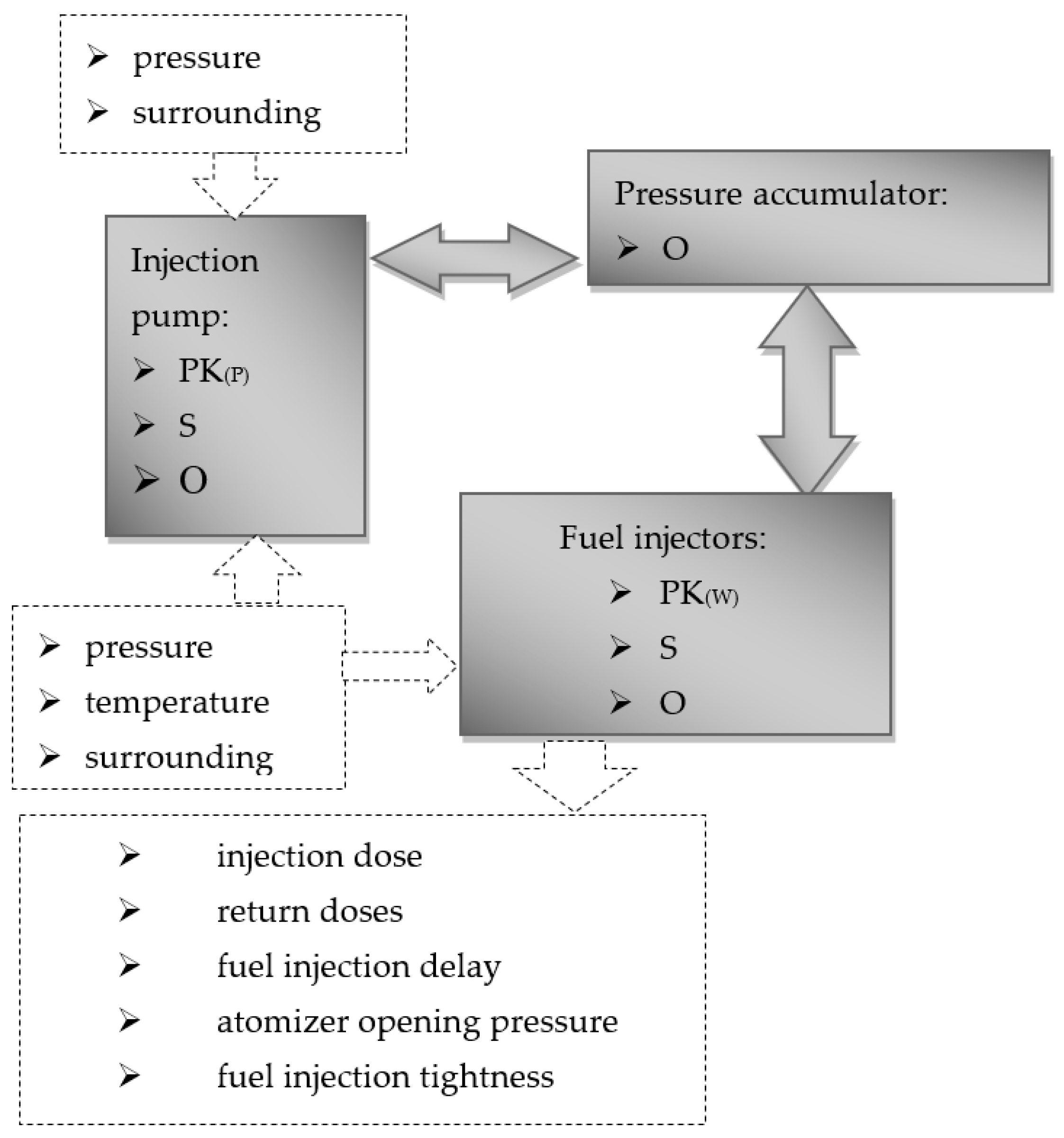
The operating conditions of the Common Rail system intensify the wear processes of its individual components. Elements of precision pairs on the fuel injector wear out the fastest during operation. The wear processes of elements of the CR injection system can be divided into tribological and non-tribological. Most often, the phenomena of the intensity of consumption of elements of the fuel supply system overlap. Phenomena occurring in the fuel supply system related to the operation and wear of individual components can be considered in terms of the system. The tribological system of the injection system components consists of kinematic pairs, lubricant, and the surroundings. Kinematic pairs (PK) are tribological associations where friction and wear processes occur and take place. Lubricant (S) is a substance whose introduction into the elements of kinematic pairs reduces their friction and wear. The immediate surroundings (O) are the operating conditions of the system. In the case of fuel supply systems, these are pressure, pollution, and operating temperatures of components.
Figure 1 shows the tribological system of the power supply system with the Common Rail system.
One of the functions of the fuel flowing through the injection pump and injectors is the lubrication of cooperating elements. Fuel lubricity is a parameter that determines its ability to minimize the friction process of elements such as precision pairs. The measure of this parameter is the durability of the surface of cooperating elements.
The system pressure creates fuel injection work parameters like injection, return doses, and fuel injection delay. The surrounding is the conditions of the whole system work like fuel and pollution. Pollution is dangerous for the whole system, especially fuel injectors, and it can be divided into external and internal sources. If fuel lubricity is not enough, it will be produced on cooperating elements in the fuel pump the metal fillings. This kind of internal pollution destroys precision elements in fuel injectors. The injection pump and fuel injectors assemble with kinematic pairs. These cooperating elements influence fuel pump discharge and injection dosages. Temperature is the diagnostic parameter and influences liquid parameters.
Viscosity is one of the properties of liquids that affects the wear processes of tribological associations. The fuel must have an appropriate viscosity because too high a coefficient makes it difficult for the liquid to flow between the friction elements and too low a coefficient reduces the lubricating properties of the liquid. In injection systems, there is a variable pressure of 25–200 MPa. The pressure exerted on the liquid brings its particles closer together and increases intermolecular interactions resulting in increased viscosity. It is assumed that up to about 25 MPa, the change in viscosity as the viscosity increases is linear, and above it is exponential. The dependence of dynamic viscosity from the pressure above 25 MPa can be represented by Barus dependence [
18,
19].
where
μ0 dynamic viscosity at atmospheric pressure,
P measured pressure,
α dynamic viscosity coefficient, which depends on the pressure.
The viscosity of the liquid decreases as the temperature increases. This phenomenon may have dangerous consequences during the work of precision pairs. When the viscosity of the liquid is too low, the internal friction resistance of the fuel decreases, then it flows out from between the friction elements. This leads to galling and accelerated wear of the injection pump or fuel injectors. When the precision pairs are leaking, leakage occurs inside them. While testing fuel injectors on the test bench an increase in the overflow dose begins to be noticeable. The area where the leakage is increased is characterized by a higher temperature due to the increased flow. This phenomenon is unfavorable because locally the fuel changes its physical properties, and lubrication of friction elements deteriorates; therefore, the more tribological associations are destroyed, the faster their degradation process during work progresses.
The tests were carried out on a Fiat 1.3 jtd vehicle with the Common Rail system. The vehicle was used in the spring and summer period for 6 months and only worked on B100 fuel. He drove about 10,000 km. Then the fuel injectors and the pump were verified. The tests showed a slight degradation of the precision elements, which affected the operating parameters of the CR system components (injection pump and fuel injectors).
A measure of the wear degree of precision pair elements can be the temperature that occurs in the area of tribological associations. As a result of reducing the tightness of precision pairs, the speed of the liquid flowing through them increases, which results in an increase in temperature. Research conducted by the authors of [
19] showed that if the overflow dose is above 60 mm
3/H, then the fuel temperature begins to increase significantly (
Figure 2).
Increased temperature in tribological associations causes a decrease in the lubricity factor of the fuel by reducing its density and viscosity. This phenomenon may accelerate the processes of precision pairs consumption of a modern fuel injector.
The analysis of damaged pumps and injectors working on biofuels shows that inside were many inorganic deposits. It means that biofuels didn’t destruct these elements.
Friction bearings propel high pressures sections in the fuel pump. This is the contact surface between the cam surface and the high-pressure piston. The cam surface layer is molybdenum disulphide (MoS
2). MoS
2 belongs to types of materials including hydrogen intercalated layered alloys (hydrogen location in the Van der Waals gap). It is known that the presence of alloying elements in the structure of modern steels, such as manganese, chromium, tin, molybdenum, and some others, reduce hydrogen permeability and, consequently, hydrogen wear [
20,
21,
22] (hydrogen content in wear products—from 3.0 up to 6.2 ppm). The main task of the layer is lowering friction forces. Due to low lubricity, this layer has been wiped off [
23,
24,
25]. Friction forces in these area increase and metal filings have been produced [
26,
27,
28,
29].
Table 1 shows the results of microscopic studies (
Figure 4) with the number of individual elements.
The area photos were taken with different zooms.
Figure 6,
Figure 7 and
Figure 8 show the plate surface of the high-pressure section analyzed by EDS at different zoom with separate areas. Common view of samples during the test (A) diesel fuel, (B) rapeseed oil methyl ester B100 (
Figure 9), local view of the surface of tested samples (A) diesel oil, (B) biofuel (
Figure 10) permit to compare influence of hydrogen-containing “green” fuels and their role in the thermal protection of structural materials at high temperature and pressure.
Table 2,
Table 3,
Table 4 and
Table 5 present the composition of the elements found during the study.
Figure 11 shows the operational characteristics of the injection pump tested.
The second stage of research was the analysis of the operation of injection apparatus on vegetable fuels. The test table for testing fuel injectors and injection pumps of modern engines with Common Rail systems was filled with B100 fuel and measurements of the injection pump outputs were carried out (
Figure 12). On the basis of the measurements carried out, the efficiency of the injection pump working on diesel and biofuel was calculated (
Figure 13). Similar tests were performed on fuel injectors. Injection and overflow doses of diesel and biofuel were measured (
Figure 14 and
Figure 15).
4. Discussion
In the first stage of laboratory tests, an injection pump was analyzed with a course of about 150,000 km operating on standard conventional fuel with a 7% addition of the B7 biocomponent. Microscopic analysis of the pump showed that the surface cooperating with the plate in a galling way is a coating of molybdenum disulphide (MoS2). Its task is to reduce the friction coefficient. Analysis in the area of cooperation with the disc showed the presence of numerous scratches on the coating MoS2, on which embedded particles of the chemical composition Si, Al, Na, O, typical for glass, were observed. The plate cooperating with the cam was made of low-alloy chromed steel for heat treatment. The plain bearing pan was made of steel with tin bronze, followed by a polytetrafluoroethylene (PTFE) coating. Impurities tests taken from the interior of the injection pump and fuel injectors were characterized by various dimensions from 1 µm to 100 µm. The chemical composition of these impurities is very diverse and contains numerous elements Ni, O, Si, Cl, P, Al, Zn, K. These elements are inorganic, of foreign origin, and not from biofuels. The operating characteristics of the tested pump showed a significant decrease in its fuel output from a pressure of about 40 MPa. This is due to numerous galling and increased local leakage of precision components. It should be noted that the deterioration of the operating parameters of the injection pump is not affected by the type of fuel used, but by significant impurities of external origin. Studies have shown that the fuel filter loses its properties with longer mileage, it flakes and passes impurities.
In order to analyze the impact of plant-derived fuels on the course of the corrosion process on the surface of the components of the injection apparatus, the tests were carried out, which consisted of immersing the fuel atomizers in diesel fuel and B100 for a period of 18 months (samples shown in
Figure 13). The samples were stored in the darkroom at 20 °C (293 K). These are the conditions prevailing inside the injection apparatus in the spring and summer. After the test, they were subjected to microscopic analysis. There were no signs of corrosion or other fuel deposits on the surfaces of the samples (
Figure 15). This means that the fuel of vegetable origin, rapeseed oil methyl ester (B100), does not cause corrosion phenomena on precision pairs elements. This discovery is important because it suggests that this type of fuel does not damage the injection apparatus and can be used in compression-ignition engines [
47,
48,
49].
The next stage of research was the analysis of the operating parameters of the injection pump and fuel injectors working on conventional fuel and hydrogen-containing B100. Studies have shown that the output of the diesel fuel injection pump is similar to that of the B100 of hydrogen-containing rapeseed oil methyl ester. However, during the tests on an electromagnetic injector for vegetable fuel, the injection dose values were smaller, especially at lower pressures. This is influenced by the physical properties of biofuels, such as viscosity, density, and surface tension, and takes in to account hydrogen degradation of structural materials [
50,
51,
52,
53]. Several factors affect the injection dose in a Common Rail electromagnetic fuel injector. The scope of the CR valve operation and the fuel injector response time from the moment the coil is actuated to the opening of the atomizer are very important. The principle of operation of CR system fuel injectors shows that the larger the range of valve operation, the greater the pressure difference between the control valve assembly and the atomizer. If the pressure difference is greater, then the needle rises higher, and the injection dose increases. The physical parameters of the fuel affect the injector response time. Increased density, viscosity, and surface tension lengthen this process, which affects the size of doses and the angle of fuel injection in the running engine. It is similar to the number of overflow doses. Increased physical parameters reduce fuel fluidity, reducing doses. The differences in dose sizes were greater for lower system pressures. This is due to the nature of the flow. Simulation tests conducted by the authors [
5] showed that at lower pressures the fuel flow velocities in the injector are lower, which at higher viscosity and density may affect its injector response, that is, the time from its activation to fuel injection into the engine’s combustion chamber.
Analyzing the conducted laboratory tests, it can be stated that vegetable fuels can be used as a source of alternative energy in compression-ignition engines. Their application should be considered in two aspects: combustion and operational in terms of wear of injection apparatus components [
48]. The exploitation aspect is presented early [
23]. Analyzing the tests performed, it can be concluded that the main reason for the deficiencies of the injection apparatus is fuel impurities from outside. They affect the number of outputs of the injection pump, injection doses, and overflow doses. In the framework of this article, rapeseed oil methyl ester B100 was used for laboratory tests. Analysis of research results shows that this type of fuel can be used as an alternative to powering modern diesel engines. The physical parameters of the tested vegetable fuel are similar to standard diesel oil. The fuel must have good properties for atomization, fluidity, and lubricity. Most scientific papers are devoted to discussing issues [
30,
44,
45] related to the distribution and spraying of fuels in the engine compartment and the combustion process itself. We focused on the second aspect of fuel as a lubricant and protection agent for injection equipment components. Studies have shown that vegetable fuels derived from rapeseed have similar lubricating properties as diesel oil. In addition, similar viscosity means that the operating parameters of the injection pump are at a similar level compared to standard fuels. Processes that destroy components cooperating with each other are supported by impurities coming from the outside, which also reduce the lubricating properties of fuels. If the lubrication capacity of the fuel decreases, friction and temperature at the interface of the associated components increase, which accelerates wear processes. The metallic filings break off from the cooperating elements, which contaminate the injection apparatus and destroy its subsequent components (fuel injectors). In order to slow down the processes of destruction of fuel equipment components, it is recommended to once a year to rinse and clean its elements (injection pump and fuel injectors) on specialized test tables, wash high-pressure lines and CR rail, and replace the fuel filter once a year or every 20,000 km. Analyzing the conducted research, it can be concluded that based on the analysis of the injection pump and its components, vegetable fuel derived from rapeseed can be used in compression-ignition engines.
5. Conclusions
Analyzing the conducted laboratory tests, it can be stated that vegetable fuels can be used as a source of alternative energy in compression-ignition engines. Their application should be considered in two aspects: combustion and operational in terms of wear of injection apparatus components.
On the base of the tests performed, it can be concluded that the main reason for the deficiencies of the injection apparatus is fuel impurities from outside. They affect the number of outputs of the injection pump, injection doses, and overflow doses. The hydrogen-containing rapeseed oil methyl ester B100 for laboratory tests has shown that this type of fuel can be used as an alternative to powering modern diesel engines.
Conducting engine tests requires using a modern sensor (including a hydrogen sniffer) to measure pressure changes in the combustion chamber on vegetable fuels, an analysis of how the changed injection doses affect the operating parameters of a modern diesel engine powered with B100, an adaptation of a modern compression-ignition engine, and injection apparatus to work on hydrogen-containing vegetable fuels.
Because the physical parameters of the tested vegetable fuel are similar to standard diesel oil, the fuel has good properties for atomization, fluidity, fugacity, and lubricity which has been reflected in the aspect of fuel as a lubricant and protection agent for injection equipment components.
It has been shown that vegetable fuels derived from rapeseed have similar lubricating properties as diesel oil. In addition, similar viscosity means that the operating parameters of the injection pump are at a similar level compared to standard fuels.
It has been established that impurities coming from the outside destroy components, which also reduces the lubricating properties of fuels. If the lubrication capacity of the fuel decreases, friction and temperature at the interface of the associated components increase, which the accelerates wear process.
Metallic filings break off from the cooperating elements, which contaminate the injection apparatus and destroy its subsequent components (fuel injectors). In order to slow down the processes of destruction of fuel equipment components, it is recommended to once a year to rinse and clean its elements (injection pump and fuel injectors) on specialized test tables, wash high-pressure lines and CR rail, and replace the fuel filter once a year or every 20,000 km.

 ,
, 


