Abstract
With the rapid growth of the power grid load and the continuous access of impact load, the range of power system frequency fluctuation has increased sharply, rendering it difficult to meet the demand for power system frequency recovery through primary frequency modulation alone. Given this headache, an optimal control strategy for battery energy storage participating in secondary frequency regulation of the power grid is proposed in this paper based on a double-layer structure. Besides, a coordinated control framework is constructed for energy storage battery joint units engaged in automatic generation control (AGC). At the dispatching level, the power allocation principle is set to coordinate the fast and slow resources of energy storage and conventional thermal power units, and the power decoupling of the two types of frequency modulation (FM) resources is completed. At the system level, a power allocation model representing the real-time frequency modulation capability of energy storage is established to realize the division of frequency modulation responsibilities of each unit and state of charge (SOC) consistency management, and the proposed control strategy is simulated and verified to provide a reference for the energy storage battery to participate in the secondary frequency modulation design of the power grid.
1. Introduction
With the rapid consumption of fossil energy and the increasingly serious problem of environmental deterioration, the survival and development of human society are facing severe challenges. As a result, the focus of attention of countries around the world has shifted to promoting the transformation of energy structure and achieving low-carbon green development [1]. The development of clean energy has been paid attention to by many countries. The large-scale development and utilization of wind energy and solar energy, the most crucial clean energy in the 21st century, has become an effective method to realize sustainable development. Secondary frequency modulation is a vital method of frequency stability control in a power system. Under the background of large-scale grid connection of high permeability wind power and photovoltaic power generation, nonetheless, the traditional FM power units and hydropower units in China cannot effectively meet the frequency regulation needs of the power system owing to its defects such as slow response rate, low control precision, and insufficient regulation capacity [2,3]. Therefore, a more high-quality frequency modulation power supply to serve the power system frequency stability control should be urgently designed to improve the security and quality of power grid frequency under the background of new energy grid connection [4].
In the past few years, electrochemical energy storage technology has developed rapidly, and its capacity has been expanding, allowing energy storage to participate directly in power grid frequency modulation [5]. Some research progress has been made in the field of energy storage engaged in secondary frequency modulation control. Among them, the research on the coordinated control between energy storage and unit aims to demonstrate the resource allocation of energy storage and conventional unit frequency modulation. Considering the SOC of energy storage equipment participating in secondary frequency modulation, a dynamic allocation method of maximum available frequency modulation capacity between conventional units and energy storage system based on ACE signal allocation was proposed [6,7]. Power decomposition [8] was presented, in which the power demand signal is decomposed, the energy storage bears the high-frequency component with fast-changing speed, and the unit bears the trend low-frequency component. The frequency modulation signal was decomposed by discrete Fourier transform, and the frequency modulation responsibility of unit and energy storage was divided in the frequency domain [9]. A multi-objective optimization model including frequency modulation effect, SOC state, and energy storage loss cost was constructed to realize the optimal allocation of energy storage and unit frequency modulation signals in each cycle [10]. The reasonable allocation of different frequency modulation resources on the basis of ensuring the solution speed and accuracy was realized by establishing the loss function of unit and energy storage and using distributed control algorithm [11], enlightening the coordinated and optimal control of unit and energy storage.
The research on the optimal control strategy of energy storage participating in secondary frequency modulation contributes to coordinating the contradiction between the power demand of energy storage and the maintenance of the SOC effect in the process of responding to secondary frequency modulation so as to achieve the efficiency of frequency regulation under effective capacity. A control strategy of using fuzzy control for energy storage to participate in AGC was proposed [12]. The simulation results suggested that fuzzy control had a better control effect than traditional PI control. The energy storage control strategy considering SOC was drawn [13], in which fuzzy control was adopted to realize the smooth correction of energy storage system output in the process of real-time power exchange of the energy storage power grid. The adaptive output law of energy storage secondary frequency modulation was constructed by using a logistic regression function based on real-time state perception and comprehensive research of the power grid and energy storage battery [14]. This research considered the requirements of energy storage frequency modulation capacity and SOC maintenance and recovery. Additionally, the power signal of load disturbance should be reasonably allocated to each unit of the energy storage system, and the life of the energy storage system can be accelerated if the SOC and capacity loss of each unit are neglected [15]. It was verified that the reasonable distribution of power among the units of the energy storage system and the maintenance of SOC consistency control could not only protect the health of each unit battery but also maximize the overall capacity of the energy storage system [16]. In the above research, there is almost no comprehensive consideration of the technical characteristics of energy storage and conventional units in the energy storage participating in the secondary frequency modulation control strategy. Moreover, the coordination between the unit and the energy storage unit in response to the dispatching AGC instruction should be further investigated. The division of FM responsibility among the units of a large-scale energy storage system when undertaking the secondary frequency modulation power signal also requires further research.
Therefore, a battery energy storage secondary frequency modulation control strategy based on the double-layer structure is proposed in this paper to explore energy storage participating in the real-time dynamic allocation strategy of secondary frequency modulation in the power grid. In the dispatching layer, the technical characteristics of the secondary frequency regulation of the conventional unit and the energy storage battery are comprehensively compared, and the power distribution principle for the coordination of the energy storage battery and the conventional unit is designed. In the energy storage system layer, a power allocation model for quantifying the secondary frequency modulation capacity of the energy storage unit is established based on the frequency modulation cost function to realize the SOC consistency management of the energy storage system and the reasonable transfer of different energy storage unit resources in the secondary frequency modulation response process. The proposed control method is verified based on the simulation platform. The results lay a foundation for the energy storage battery to function in the secondary frequency modulation design of the power grid.
2. Basic Structure and Control Mode of AGC
AGC is an essential means to maintain the active power balance and system frequency stability in the power system. When the system encounters a large load disturbance, the system frequency cannot be stabilized within the allowable range only by primary frequency modulation. In other words, secondary frequency modulation should make the area control deviation area control error (ACE) zero or within the normal range to restore the frequency to the rated or allowable range. The secondary frequency modulation is generally realized through the AGC system, and the dispatching center directly controls the unit to increase or decrease the output [17]. The system control structure is illustrated in Figure 1.
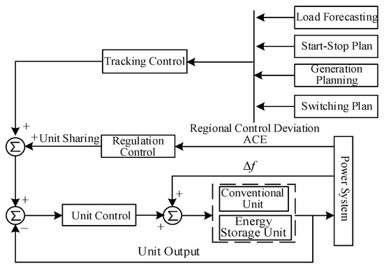
Figure 1.
AGC control system structure.
The AGC dispatching center collects the power network operation parameters (including the system frequency deviation Δf and the tie line plan deviation ΔPtie), calculates the regional control error value ACE, and obtains the smooth ACE signal value after filtering. After the conversion of the PI controller, the regional control demand value area regulation requirement (ARR) is formed. ARR represents the unbalanced power between the generation and the load in the regional power system, namely, the power that should be adjusted by each AGC unit. Each frequency modulation power supply is sent by the AGC system of the dispatching center. Each part of the resource tracks the output according to the received AGC instructions to complete the AGC control requirements [18]. The specific process is exhibited in Figure 2.

Figure 2.
Schematic diagram of ARR signal generation.
At present, there are three basic control modes of AGC during power adjustment of the regional power grid in the interconnected system [19]:
- (1)
- Flat Frequency Control (FFC)
This control mode keeps the frequency deviation of the regional power grid system unchanged. When the impact load disturbance occurs, the AGC control system in each region only responds to the change of frequency deviation and adjusts the power output of the FM power supply until Δf = 0.
where B denotes the regional frequency deviation coefficient (MW/Hz). FFC control is generally applicable to individual power systems or the main system of the Internet. In the interconnected power grid, at most, one area can adopt the FTC control strategy.
- (2)
- Flat Tie-line Control (FTC)
This control mode maintains the exchange power of the tie line constant. When a disturbance occurs, each regional system responds to the change in the tie line until ΔPtie = 0.
FTC control is generally suitable for small- and medium-capacity systems in interconnected power grids. Additionally, another regional power grid needs to adopt FFC or TBC mode to guarantee the stable operation of the interconnected power grid when the regional power grid adopts FTC control.
- (3)
- Tie-line load Frequency bias Control (TBC)
This control mode realizes the constant deviation of tie line exchange power and regional frequency simultaneously. The ACE signal consists of two parts: the frequency deviation information of the regional power network of the system and the power deviation component of the tie line, as expressed in Equation (3).
Under the condition of proper B value setting, the regional power grid with TBC control mode can judge whether the load change occurs in this area, the units in this area only respond to the load disturbance in this area, and other regional power grids only play a power-supporting role Pin the regulation process. The load change is ultimately borne by the region.
In the interconnected power grid, different regional power grids may adopt different control methods. Various strategies are available to cooperate with each other to ensure the best performance of the system frequency control. With the two regional power grid interconnected systems as an example, the control modes between the two regional interconnected systems are mainly divided into six types. Their specific cooperation modes, characteristics, and main matters are detailed in Table A1 in Appendix A.
The research of secondary frequency modulation in this work is based on two regional interconnected systems. TBC-TBC is selected for the AGC control mode to effectively reflect the tracking of load changes by FM resources in the disturbance area.
3. Research on Coordinated Control Strategy of Energy Storage and Conventional Units
All the selected units are thermal power units. In the process of participating in the secondary frequency modulation, its characteristics are compared with the battery energy storage system, as listed in Table A2 in Appendix A. The advantage of energy storage and frequency modulation lies in the speed and precision of regulation, as well as the storage and release of electric energy through an electrochemical reaction. Moreover, its power can be adjusted greatly and quickly in a short time, providing fast power support to the power system. Nonetheless, it is not a primary power generation equipment, the energy comes from the power grid, and the charge and discharge capacity is limited [20].
The defect of the thermal power unit is attributed to its poor performance of physical regulation, such as mechanical operation, which cannot effectively track the rapid change of AGC instruction. However, its energy supply is unlimited, and it can provide sufficient energy support for the system when the one-way regulation time of secondary frequency modulation instruction is too long.
Thus, a strategy of coordination between thermal power units and large-scale energy storage is proposed. The basic idea is depicted in Figure A1 in Appendix A, which is a schematic diagram of coordinated control between thermal power units and energy storage. The proposed strategy only needs to add the energy storage AGC control module instead of changing the existing AGC control structure of the unit. The combination of traditional slow frequency modulation resources and high-quality fast energy storage frequency modulation resources can improve the effectiveness of secondary frequency modulation control, reduce energy storage time and electricity demand and give full play to the dual advantages of both. The specific control strategy is divided into two parts: the optimal management of energy storage battery SOC in the dead zone and the dynamic power replacement in the process of regulation.
- (1)
- FM dead zone
When in the FM dead zone, the energy storage and thermal power units do not act, and the unit in the energy storage system adjusts its own charge state to about 50% following the change of the system frequency so as to achieve a better up and down adjustment state.
- (2)
- Dynamic power replacement in the process of regulation
When the AGC regulation control starts, the energy storage first receives all AGC instructions to give priority to output and then judges whether the overall SOC state of the battery in its own system is in the usable range.
If Equation (4) is not satisfied, the state of the whole energy storage system is poor. Meanwhile, the energy storage system feedbacks the information to the dispatching center and does not participate in the AGC control. If Equation (4) is satisfied, it can participate in the AGC output control. The energy storage system can give fast power support to the system by giving full play to its characteristics of strong short-term handling capacity and being free from climbing restrictions. Concurrently, it adjusts the receiving instruction value according to the output information of the slow FM unit and replaces its own energy, specifically:
- (1)
- If the command demand value is less than the full output of the initial stage of the energy storage power station. The energy storage power station receives the instruction output quickly and reaches the power demand value. After the output of the unit, the output of the energy storage power station is gradually reduced, and its signal is changed from the original AGC command to the deviation between the unit and the AGC signal.
- (2)
- If the command demand is greater than the full output of the initial stage of the energy storage power station, the energy storage power station receives the instruction, and the first rated power output is fast. After the output of the unit, the power instruction signal is changed to Equation (5) until the sum of the total output of the energy storage power station and the unit output reaches the gradual exit of the power command energy storage system. Besides, the energy storage stops until the output of the unit completely meets the power demand.
4. Research on Power Allocation Strategy of Energy Storage System Considering SOC Consistency
After the AGC system starts to operate, the energy storage power station receives the instructions from the AGC dispatching side and sends out the power quickly, thus fully compensating for the shortcomings of long response time and low climbing rate of traditional thermal power units. When the energy storage power station receives instructions from the upper AGC dispatching layer, the main control unit decomposes the PB and sends it to each actual energy storage unit for control, and multiple energy storage units cooperate to complete the charge and discharge requirements of the energy storage power station, as suggested in Equation (5).
Inspired by the unit frequency modulation cost, an optimal allocation method of energy storage power station based on a cost evaluation model is proposed. The frequency modulation capacity of each energy storage unit in each frequency modulation cycle is quantified by establishing the frequency modulation evaluation function of each unit of the energy storage power station. Subsequently, the best output power reference value of each unit is obtained by way of model optimization, and the power responsibility division of each unit is managed finely so as to minimize the cost of the secondary frequency modulation of the energy storage power station. Meanwhile, the charge state of each unit is set to be consistent.
When the unit carries out secondary frequency modulation, its power reference point is changed in accordance with the dispatching control instructions, causing it to deviate from the best economic operating point. Consequently, coal consumption increases, and unit efficiency decreases. Furthermore, the cost of secondary frequency modulation of the unit is generated, which can be approximately expressed by quadratic function [21,22].
where CG,i represents the cost of secondary frequency modulation of unit i; ai indicates the cost weight coefficient increased by the unit power offset; PG,i denotes the power responsibility of the unit when it participates in the secondary frequency modulation. In AGC control, reasonable scheduling can be performed following the frequency modulation cost of different units. Thus, the AGC cost control tends to the minimum, contributing to giving full play to the available frequency modulation capacity of different units.
Different from the intuitive increasing cost of primary energy consumption and mechanical loss caused by unit output power, the loss of power electronic devices in the process of power storage is negligible. Its most notable feature is the change in electricity caused by power output. There are two main aspects of the impact of power changes on energy storage batteries:
- (1)
- The charge and discharge depth is too large, putting the battery in a state of too high or too low SOC and then leading to the aging and life decline of the energy storage unit.
- (2)
- The SOC deviates too much from the optimal operating point of the battery QSOC,ref, as exhibited in Figure 3. (QSOC,ref = 50% ensures that the energy storage has sufficient bi-directional regulation capacity), and the subsequent operation efficiency of the energy storage unit decreases.
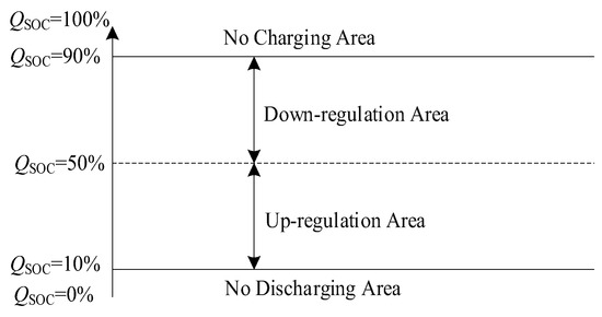 Figure 3. Schematic diagram of up- and down-regulation of energy storage unit.
The established FM cost of the energy storage unit is expressed using the quadratic function expression.
where in τ represents the cost coefficient caused by the SOC offset of the energy storage unit, Erate denotes the rated capacity of the energy storage unit, and QSOC,i(t) signifies the SOC value of the i-th energy storage unit at time t.
According to the ampere-hour method, the relationship between SOC and energy storage secondary frequency modulation output power value Pb,i is expressed as:
By substituting Equation (8) into Equation (7), the cost function of a single energy storage unit with the output power as a variable can be obtained.
Therefore, the objective function of the power allocation model of a large-scale energy storage system is:
wherein n represents the total number of FM energy storage units in a large-scale energy storage system, and the objective function is a univariate quadratic polynomial.
The expression for the quadratic part is:
The partial expression of the item is:
The constant term is:
The sum of the output power Pb,i of each unit in the large-scale energy storage system should be the total output of the energy storage system to construct the equality constraint condition. According to the output power of each unit and the SOC limit, the inequality constraint is constructed, and the constraint condition of the objective function is expressed as:
where Pb,i,max represents the maximum power output of the energy storage unit; QSOC,min and QSOC,max denote the upper and lower limits of the charge state of the energy storage battery; the positive and negative of ΔPB indicate the overall discharge and charging state of the energy storage power station, respectively.
The objective function of the model is in the form of nonlinear programming. Cost minimization can ensure the economic optimality of power distribution in each calculation cycle, guarantee that the energy storage unit with the sufficient state is called first, realize the efficient utilization of the energy storage power station, and enable the charge state of each unit to be consistent gradually. The power distribution process of the energy storage power station based on the FM cost function is depicted in Figure A2 in Appendix A.
5. Example Simulation
In order to validate the proposed control strategy, a dynamic simulation model of a two-region interconnected power network is constructed in this paper by using the call wire model and the regional power network frequency modulation model on the Matlab/Simulink platform. It is assumed that the units of the same type in each regional power network are equivalent to a single unit which is divided into an AGC unit and a non-AGC unit. Since this section focuses only on studying and verifying the dynamic changes of secondary frequency modulation, the AGC unit and energy storage system are involved only in the process of secondary frequency modulation, while the primary frequency modulation is completed by the non-AGC unit. In the simulation model, the parameters of the two regional grids are set to be the same, as shown in Table 1.

Table 1.
Simulation model parameters.
The proposed double-layer structure optimization control strategy is analyzed through simulation under two typical working conditions: step load disturbance and continuous load disturbance. At the level of power distribution between the energy storage system and the conventional unit, a comparative simulation is performed under three different scenarios. The first one is that only the units are involved (no energy storage). The second one is that energy storage and units are distributed according to the conventional static fixed ratio (① The participation factor α is set as 0.1 according to a frequency modulation capacity ratio of energy storage that ranges from 10% to 15% in the grid; ② In order to further highlight the outcome of energy storage regulation and ensure that the power output is equally shared between the energy storage system and the units, the participation factor α is set as 0.5). The last one is that the proposed method is applied.
- 1.
- Step load disturbance.
Simulation setting: at 1 s, suppose the small wind turbine of 0.03 pu in area 1 is suddenly off the grid due to an accident, resulting in the impact load disturbance of 0.03 pu to the system. The initial SOC values of each unit of the energy storage system are 0.63, 0.60, and 0.58, respectively, and the simulation time is 300 s. At the time of disturbance, the primary frequency modulation of the unit carries on the frequency response, while the dispatching center sends the instruction to carry on the secondary frequency modulation.
Figure 4a,b show the total output of the energy storage system and the corresponding average SOC changes as observed during the process of secondary frequency modulation when the energy storage system is distributed at a fixed ratio, and the proposed method is applied. In the initial stage, the output power of the energy storage system increases rapidly to about 0.013 pu, while the average SOC decreases rapidly to 0.5435 at about 126 s. However, as the output of the unit increases, fast power support is provided by the energy storage system, and its power is replaced by the output power of the unit. Then, the SOC shows no changes as the output is gradually reduced. Throughout the process of frequency modulation, the amount of energy consumption reaches about 0.05985 MWh. The energy storage system is freed from the task of frequency modulation, with a higher state left to deal with the other tasks of the system. Additionally, the energy storage power station has no impact on the control of traditional frequency modulation resources. Given the distribution at a fixed ratio and the participation factor α = 0.1, its high climbing characteristics fail to play out effectively despite the low-frequency modulation power, and there is no advantage shown in the SOC retention effect. When α = 0.5, the power consumption is about 2.64 times that of the proposed method for the same effect of frequency modulation to be achieved, despite an equivalent effect of frequency modulation.
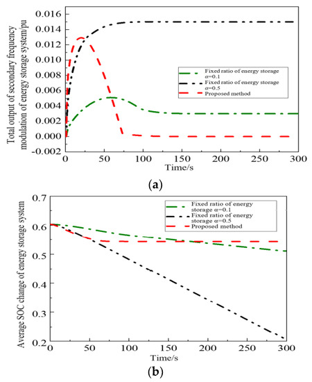
Figure 4.
Change of total output and average SOC of energy storage unit under step disturbance. (a) Variation in total output of energy storage system. (b) Average SOC change of energy storage system.
- 2.
- Continuous disturbance.
A period of 1 h continuous load disturbance is added to the regional power grid 1 to verify the frequency regulation effect of the method in this paper under continuous load disturbance. Its load disturbance curve is presented in Figure 5. The initial SOC of each unit is 0.53, 0.60, and 0.40, respectively. The non-AGC unit carries on the primary frequency modulation. The AGC unit and the energy storage unit only carry on the secondary frequency modulation. The simulation time is set to 3600 s.
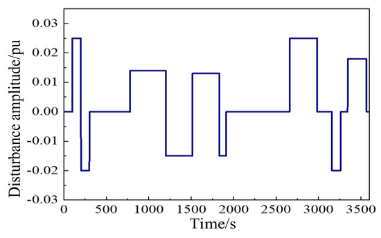
Figure 5.
Continuous load disturbance.
Figure 6 illustrates schematic diagrams of the total output change and the average SOC change of the energy storage system under the fixed proportion distribution and the proposed method.
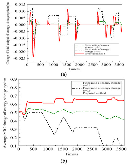
Figure 6.
Variation of total output and average SOC of energy storage system under continuous disturbance. (a) Changes in the total output of the energy storage system. (b) Average SOC change of energy storage system.
Figure 6 demonstrates that, under the proposed method, energy storage only plays a role in the process of frequency recovery, and the output is significant at the initial stage of load disturbance. The energy storage system will no longer contribute to maintaining its own state to cope with other unexpected situations when the frequency is restored, and the unit undertakes the task of active power balance. However, the SOC mean square value of the proposed method is not as good as the fixed distribution mode of α = 0.1, attributed to the drastic change of power at the initial stage.
Regarding the changes in the output and SOC of each unit in the energy storage system, the proposed optimal allocation method is compared with the traditional capacity allocation method.
As revealed in the comparison of Figure 7, the energy storage system distributed evenly in capacity ignores the available FM power state of each unit and bears the same power responsibility. The change in SOC is exhibited in Figure 8a. There is always a difference in SOC status.
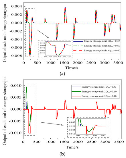
Figure 7.
Output of energy storage unit under two distribution methods. (a) Output of each unit of the energy storage system evenly distributed by capacity. (b) Output of each unit under the proposed optimization method.
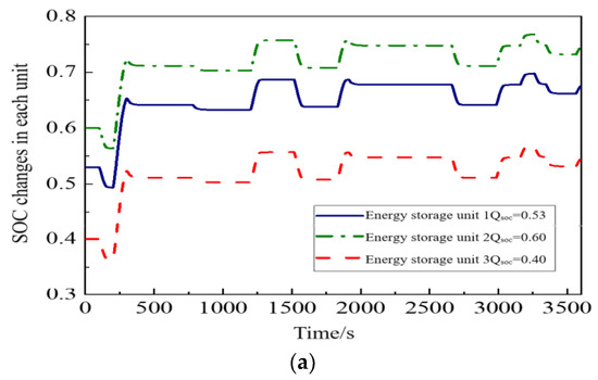
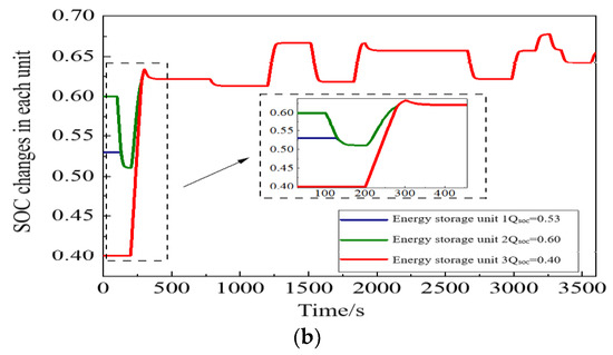
Figure 8.
SOC changes of energy storage unit under two distribution methods. (a) SOC changes of each unit under the traditional average distribution. (b) SOC changes in the allocation of units under the proposed optimization method.
In the proposed optimal allocation method (Figure 7b), the energy storage unit of QSOC = 0.60 and 0.53 is called first when the load demand is positive and bears the main responsibility of FM; when the load demand is negative, the energy storage unit of the minimum QSOC = 0.40 is charged first because of the maximum adjustable capacity. With The increasing power demand, the other two units are called in turn to realize the reasonable distribution of FM responsibility of energy storage units in different states under different charge and discharge conditions. The three energy storage units SOC converge consistently at 285 s, as reflected in Figure 8b.
- 3.
- Performance evaluation.
As suggested by the reviewer, the details about the performance evaluation have been provided as follows: As shown in Figure 9 and Table 2, the performance of the unit in frequency regulation is the worst only in the case of secondary frequency regulation. Judging from the frequency deviation curve, ACE variation curve, and the change in transmission power of the interconnection line, it can be concluded that multiple overshoots occurred only under the function of the unit, which increased the inconsistency of power grid frequency to some extent. Due to the limit of ramp rate, the unit is not applicable to track load changes in real-time, which is a disadvantage in severe frequency regulation. With the support of the energy storage system, there is an effective improvement made to the recovery of system frequency and the tracking effect of AGC commands. Furthermore, the overall response capability is increased for the regional power grid secondary frequency regulation. Thus, the traditional static allocation method is adopted. When α = 0.1, energy storage improves not only the frequency regulation characteristics of the power grid but also the tracking performance of load changes. However, partial overshoots occur due to their small proportion. When the participation factor is increased to 0.5, the performance of the system in frequency regulation is significantly improved. Because of its high power consumption, the energy storage system is forced to exit frequency regulation completely. Meanwhile, vacancy results from the power changes originally caused by energy storage, and the unit fails to compensate in a timely manner, thus reducing the frequency.
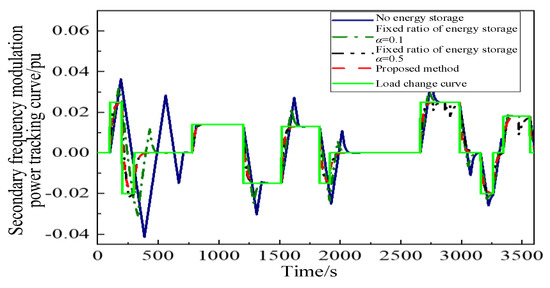
Figure 9.
Output of secondary frequency modulation in Region 1.

Table 2.
Related indicators to secondary frequency modulation.
The proposed method gives full play to the ability of high climbing to provide power support in the early stage, and it can be used to track the load changes in time. Even when the load is suddenly reversed, tracking can still be performed effectively, which improves the transient frequency of the system significantly. When the frequency is stabilized, the unit offers energy support, with better coordination achieved between the two. At the same time, the participation and exit of energy storage have no effect on the existing AGC control system.
6. Conclusions
In this paper, an optimal control strategy for secondary frequency modulation of the energy storage system is proposed. Specifically, the principle of fast and slow resource power allocation between an energy storage battery and the conventional unit is determined at the dispatching level based on the analysis of the characteristics of frequency modulation technology of the conventional unit and energy storage battery. At the system level, a power allocation model is established to characterize the secondary frequency modulation capability of each unit in the energy storage system in accordance with the frequency modulation cost function. Additionally, the quadratic programming algorithm is employed to solve the optimal output power, and the fine management of the responsibility proportion of each FM unit is realized so as to minimize the cost. The simulation results reveal that the proposed control strategy can give full play to the performance advantage of a high climbing rate of energy storage battery, improve the effect of AGC control of the power grid, avoid excessive loss of battery power, and realize reasonable scheduling and consistent control of energy storage resources.
Author Contributions
Conceptualization, Y.R. and G.M.; methodology, F.Z.; software, C.Q.; validation, Y.R., G.M. and J.X.; formal analysis, Y.C.; investigation, Y.R.; resources, F.Z.; data curation, G.M.; writing—original draft preparation, F.Z.; writing—review and editing, G.M.; visualization, J.X.; supervision, Y.C.; project administration, G.M.; funding acquisition, Y.R. All authors have read and agreed to the published version of the manuscript.
Funding
This research was funded by the Key Research and Development Program of Jiangsu Province, grant number (20KJB480006) and the Open Research Fund of Jiangsu Collaborative Innovation Center for Smart Distribution Network, Nanjing Institute of Technology, grant number (XTCX 202207).
Data Availability Statement
Not applicable.
Conflicts of Interest
The authors declare no conflict of interest.
Appendix A
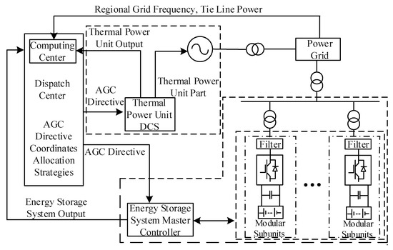
Figure A1.
Schematic diagram of coordinated control of thermal power and energy storage.
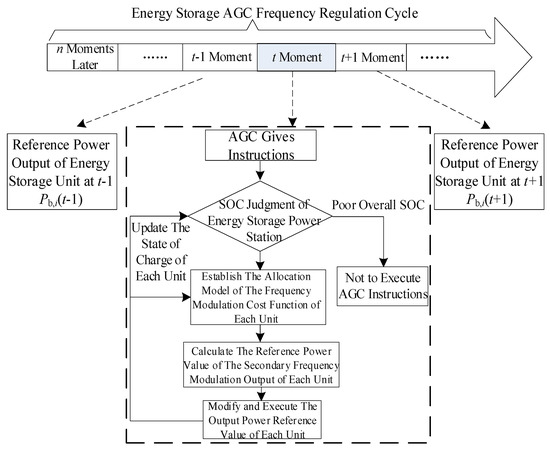
Figure A2.
Power distribution flow of energy storage station based on frequency modulation cost function.

Table A1.
Cooperate with AGC control mode of interconnected power grid.
Table A1.
Cooperate with AGC control mode of interconnected power grid.
| Control Mode Coordination | Features and Precautions |
|---|---|
| FFC-FFC | It will cause the power exchange disorder of the interconnected grid, which is not recommended in practice |
| FFC-FTC | It is generally not recommended and is limited to the interconnection between large-capacity and small-capacity grids |
| FFC-TBC | It can be used for interconnection between power grids, usually using FFC control for large-capacity power grids |
| FTC-FTC | It is not allowed, this method cannot effectively control the frequency and even cause the system to crash |
| TBC-FTC | It is not recommended because it hinders and burdens frequency recovery |
| TBC-TBC | When the frequency deviation coefficient B is selected reasonably, it is recommended to use it only for the load disturbance in this area |

Table A2.
Comprehensive comparison of energy storage and thermal power unit technical performance.
Table A2.
Comprehensive comparison of energy storage and thermal power unit technical performance.
| Technical Performance | Energy Storage | Thermal Power Unit |
|---|---|---|
| Response time | Quick response | There is energy conversion, mechanical action process, slow speed |
| Regulating speed | The climbing rate is high, which can reach the instruction value quickly | Low climbing rate and slow adjustment speed. |
| Adjusting precision | Easy to change size and direction, high tracking accuracy | There are mechanical time delay and other effects, such as overshoot, under-adjustment, and reverse adjustment |
| Regulating capacity | Subject to the conditions of capacity and state of charge | The output is continuous, and there will be no energy shortage in a certain period of time |
References
- Xie, X.R.; He, J.B.; Mao, H.Y. New Issues and Classification of Power System Stability with High Shares of Renewables and Power Electronics. Proc. CSEE 2021, 41, 461–475. [Google Scholar]
- Wang, K.F.; Xie, L.R.; Qiao, Y.; Lu, Z.X.; Yang, H. Frequency modulation performance analysis of power system improved by battery energy storage. Power Syst. Autom. 2022, 46, 174–181. [Google Scholar]
- Zhang, Z.G.; Kang, C.Q. Challenges and prospects for constructing the new-type power system towards a carbon neutrality future. Proc. CSEE 2022, 42, 2806–2818. [Google Scholar]
- Li, Z.W.; Fang, Y.J.; Li, W.; Liu, F.; Xu, G.; Wang, C. Discussion on Application of Electrochemical Energy Storage in Three Defense Lines of Power Grid Frequency. Autom. Electr. Power Syst. 2020, 44, 1–7. [Google Scholar]
- Zhang, F.; Hu, Z.C.; Xie, X.; Zhang, J.; Song, Y. Assessment of the Effectiveness of Energy Storage Resources in the Frequency Regulation of a Single-Area Power System. IEEE Trans. Power Syst. 2017, 32, 3373–3380. [Google Scholar] [CrossRef]
- Ye, L.; Wang, K.F.; Lai, Y.N.; Chen, H.; Zhao, Y.N.; Xu, X. Analysis of power system frequency characteristics under low inertia and review of battery energy storage frequency modulation control strategy. Power Grid Technol. 2023, 47, 446–462. [Google Scholar]
- Yan, G.G.; Liu, Y.; Duan, S.M. Power allocation strategy of battery energy storage unit group participating in power system secondary frequency modulation. Autom. Electr. Power Syst. 2020, 44, 26–34. [Google Scholar]
- Shu, P.; Jose, E.T. Capacity Scheduling of Energy Storage and Conventional Generation for Frequency Regulation Based on CPS. IEEE Trans. Power Syst. 2021, 35, 405–414. [Google Scholar]
- Hu, Z.C.; Xie, X.; Zhang, F.; Zhang, J.; Song, Y. Research on Automatic Generation Control Strategy Incorporating Energy Storage Resources. Proc. CSEE 2014, 34, 5080–5087. [Google Scholar]
- Li, J.H.; Hou, T.; Yan, G.G.; Li, C.; Mu, G. Two-layer optimization of frequency modulation power in multi-battery energy storage system considering frequency modulation cost and recovery of state of charge. Proc. CSEE 2021, 41, 8020–8033. [Google Scholar]
- Zhang, S.Q.; Yuan, B.; Ji, Z.D.; Wei, X.J.; Zhao, J.F. A Secondary Frequency Control Based on the Distributed Control Theory Considering Battery Energy Storage Systems. Trans. China Electrotech. Soc. 2019, 34 (Suppl. S2), 637–645. [Google Scholar]
- Ding, D.; Liu, Z.Q.; Yang, S.L.; Wu, X.G.; Li, T.T. Battery energy storage aid automatic generation control for load frequency control based on fuzzy control. Power Syst. Prot. Control 2015, 43, 81–87. [Google Scholar]
- Li, P.Q.; Tan, Z.X.; Zhou, Y.J.; Li, C.; Li, R.; Qi, X. Secondary Frequency Regulation Strategy with Fuzzy Logic Method and Self-Adaptive Modification of State of Charge. IEEE Access 2018, 6, 43575–43585. [Google Scholar] [CrossRef]
- Li, R.; Li, X.R.; Tan, Z.X.; Ma, Z. Integrated Control Strategy Considering Energy Storage Battery Participating in Secondary Frequency Regulation. Autom. Electr. Power Syst. 2018, 42, 74–82. [Google Scholar]
- Yan, S.J.; Wang, L.H.; Yan, W.H.; Gao, W. Sampled-Data-Based Consensus Control for Large-Scale Energy Storage System. J. Northeast. Univ. Nat. Sci. 2020, 41, 1528–1534. [Google Scholar]
- Nguyen, D.H.; Khazaei, J. Multi-agent Time-Delayed Fast Consensus Design for Distributed Battery Energy Storage Systems. IEEE Trans. Sustain. Energy 2018, 9, 1397–1406. [Google Scholar] [CrossRef]
- Sun, B.Y.; Liu, Z.Q.; Yang, S.L.; Wang, R.; Li, T. A real-time optimization method of compensation degree for storage coordinated with thermal power unit in AGC. Power Syst. Technol. 2018, 42, 426–433. [Google Scholar]
- He, J.; Shi, C.; Wei, T.; Jia, D. Stochastic model predictive control of hybrid energy storage for improving AGC performance of thermal generators. IEEE Trans. Smart Grid 2021, 13, 393–405. [Google Scholar] [CrossRef]
- Hu, Z.C.; Luo, H.C. Research Status and Prospect of Automatic Generation Control with Integration of Large-scale Renewable Energy. Autom. Electr. Power Syst. 2018, 42, 2–15. [Google Scholar]
- Zou, B.C.; Du, Z.J.; Yao, F.W.; Guo, Y. Coordination optimization of thermal power units based on area control error (ACE) mode. Tech. Autom. Appl. 2021, 40, 34–40. [Google Scholar]
- Megel, O.; Liu, T.; Hill, D.J.; Andersson, G. Distributed Secondary Frequency Control Algorithm Considering Storage Efficiency. IEEE Trans. Smart Grid 2018, 9, 6214–6228. [Google Scholar] [CrossRef]
- Li, N.; Zhao, C.H.; Chen, L.J. Connecting automatic generation control and economic dispatch from an optimization view. In Proceedings of the American Control Conference, Denver, CO, USA, 4–6 June 2014; pp. 735–740. [Google Scholar]
Disclaimer/Publisher’s Note: The statements, opinions and data contained in all publications are solely those of the individual author(s) and contributor(s) and not of MDPI and/or the editor(s). MDPI and/or the editor(s) disclaim responsibility for any injury to people or property resulting from any ideas, methods, instructions or products referred to in the content. |
© 2023 by the authors. Licensee MDPI, Basel, Switzerland. This article is an open access article distributed under the terms and conditions of the Creative Commons Attribution (CC BY) license (https://creativecommons.org/licenses/by/4.0/).