Article

CoOx-Fe3O4/N-rGO Oxygen Reduction Catalyst for Anion-Exchange Membrane Fuel Cells

1
The Wolfson Department of Chemical Engineering, Technion–Israel Institute of Technology, Haifa 3200003, Israel
2
CO2 Research and Green Technologies Centre, Vellore Institute of Technology (VIT), Vellore 632014, Tamil Nadu, India
3
The Nancy & Stephen Grand Technion Energy Program (GTEP), Technion–Israel Institute of Technology, Haifa 3200003, Israel
*
Author to whom correspondence should be addressed.
Energies 2023, 16(8), 3425; https://doi.org/10.3390/en16083425
Submission received: 15 March 2023 / Revised: 5 April 2023 / Accepted: 11 April 2023 / Published: 13 April 2023
(This article belongs to the Section D2: Electrochem: Batteries, Fuel Cells, Capacitors)

Abstract

:
Platinum group metal (PGM)-free oxygen reduction reaction (ORR) catalysts are of utmost importance for the rapid development of anion-exchange membrane fuel cell (AEMFC) technology. In this work, we demonstrate the improved ORR performance and stability of Co and Fe oxide-decorated/N-doped reduced graphene oxide (CoOx-Fe3O4/N-rGO) prepared via a hydrothermal method at the low temperature of 150 °C. The catalysts were characterized thoroughly using transmission electron microscopy, high-angle annular dark field-scanning electron microscopy, X-ray diffraction, N2 physisorption, Raman spectroscopy, and X-ray photoelectron spectroscopy to obtain information about morphology, elemental distribution, phases, porosity, defects, and surface elemental compositions. Significant ORR activity improvement (130 [email protected] mA cm−2) was achieved with this catalyst compared to the pristine graphene oxide, and the ORR limiting current was even 12%@0.5 V higher than the commercial Pt/C. The enhanced ORR activity of CoOx-Fe3O4/N-rGO was attributed to the uniform dispersion of Co, Fe, and N on reduced graphene oxide (rGO) sheets. Furthermore, ORR accelerated stress tests revealed excellent durability, suggesting that this material could be a promising and durable catalyst. With a cathode layer of the CoOx-Fe3O4/N-rGO catalyst, we achieved a peak power density of 676 mW cm−2 in an operando H2-O2 AEMFC. To the best of our knowledge, this is the highest reported power density per cathode catalyst mass in a reported PGM-free cathode catalyst. Finally, we quantified the various cell polarization losses as a function of cathode catalyst loadings to obtain insights for future work with AEMFCs based on this catalyst. The improvement in the AEMFC performance using CoOx-Fe3O4/N-rGO as a cathode catalyst can be attributed to the synergistic effects of (i) the high turnover frequency of the transition metals (Co and Fe) for ORR and (ii) the enhancement provided by N doping to the metal distribution and stability.

1. Introduction

Anion-exchange membrane fuel cell (AEMFC) research has achieved significant progress in recent years [1,2,3,4], mainly due to improvements in anion-exchange membrane (AEM) conductivity [5,6,7,8,9,10], ionomer chemistry [6,11,12,13], cell water management [7,14,15,16], and catalyst development [17,18,19,20,21,22,23,24,25,26,27,28,29,30,31,32]. The alkaline pH of AEMFCs provides a tremendous opportunity for the development of platinum group metal (PGM)-free catalysts, which need to be utilized at both electrodes to actualize the full benefits of AEMFCs. The literature shows significant progress in developing highly active and stable PGM-free ORR catalysts [20,21,23,33,34,35,36,37,38,39,40,41,42,43,44]. Most reported PGM-free catalysts are based on Co and Fe nanoparticles embedded on either carbon or a N-doped carbon matrix, mainly because Co and Fe exhibit the highest turnover frequencies for ORR [45]. Nitrogen doping is performed due to the following reasons: (i) increased dispersion of the nanoparticles, (ii) enhanced “tethering” of the nanoparticles on the carbon support, or (iii) augmented electronic interaction with catalyst particles and carbon [46].
The best-performing PGM-free ORR catalyst showed AEMFC power densities of ~1.0 W cm−2 [22,43,47]. For instance, recent work by Peng et al. [43] on a N-C-CoOx ORR catalyst synthesized at 700 °C showed a promising cell performance of 1.05 W cm−2 with decent stability for 100 h. Other catalysts reported lower power densities but still promising performance, indicating a need for further investigation. For instance, Truong et al. [48] investigated Co3O4 mixed with carbon as a PGM-free ORR catalyst and successfully tested their performance in a cell, resulting in a peak power density of 388 mW cm−2 at 70 °C, showing their potential use in AEMFCs. Liang et al. [35] synthesized Co3O4 nanoparticles on graphene, showing impressive ORR performance in rotating disk electrode (RDE) tests. The enhanced activity was attributed to the synergistic effect between Co3O4 and graphene. The catalyst also showed improved stability in the RDE test compared to Pt/C. Most of the PGM-free catalysts discussed in the literature were synthesized in the 700–1000 °C temperature range in either inert or ammonia atmospheres [43,45,49,50,51]; however, low-temperature synthesis is rare in the literature [35].
In this work, we synthesized Fe-Co co-doped reduced graphene oxide (CoOx-Fe3O4/N-rGO) using a scalable and reproducible hydrothermal method at a low temperature of 150 °C. We modified the reported protocol, aiming to enhance catalyst durability. Fe was added along with Co in our catalyst to (i) increase the ORR turnover frequency [45] and (ii) decrease the peroxide yield [49,51]. The catalyst was characterized with a variety of analytical techniques, such as advanced electron microscopy, X-ray diffraction (XRD), Raman spectroscopy, X-ray photoelectron spectroscopy (XPS), and N2 physisorption, to gauge the structure–property relationship in the promotion of ORR activity. Significant high-performance stability was observed for this catalyst in RDE tests, and it showed no signs of degradation even after 5000 accelerated stress test (AST) load cycles. Finally, we tested the performance of the catalyst in an operando H2-O2 AEMFC using low catalyst loading and it showed a peak power density of 676 mW cm−2, a limiting current density close to 3000 mA cm−2, and the highest reported power density per catalyst mass value in the PGM-free cathode catalyst AEMFC literature. The results were validated with AEMFC modeling. The results presented in this manuscript can further guide the design of cathode catalyst layer structures to achieve improved cell performance.

2. Experiment

2.1. Materials

Graphene oxide powder (15–20 sheets, 4–10% edge-oxidized), FeCl2.4H2O (99.99% metal basis), potassium hydroxide pellets (99.9%), and Nafion® ionomer (10 wt% in water) were purchased from Sigma Aldrich (St. Louis, MO, USA). CoCl2.6H2O (99.9%), PtRu/C (40% Pt and 20% Ru on carbon black, HiSPEC® 10000), and Pt/C 60% on a high-surface-area advanced support (HiSPEC®9100) from Alfa Aesar (Haverhill, MA, USA); ammonium hydroxide (~25%, AR) from Bio Lab Israel (Jerusalem, Israel); and trimethylamine (TMA: 40 wt% in water) from Mercury, Israel, were used for catalyst synthesis and electrochemical testing. Gas diffusion layers (GDLs)—specifically, Toray Paper 060-TGP-H-060 with 5% wet-proofing and Ultraflon MP-25 Polytetrafluoroethylene (PTFE) powder—were from Fuel Cell Store (Bryan, TX, USA). VULCAN® XC-72 conductive carbon black was obtained from Cabot Corporation (Boston, MA, USA). Fumion® anion exchange ionomer (AEI) was supplied by Fumatech BWT GmbH (Bietigheim-Bissingen, Germany) and low-density polyethylene (LDPE)-AEM [52] was acquired from Professor John Varcoe’s group at the University of Surrey (Guildford, UK) and used for the fuel cell measurements. High-purity argon, oxygen, nitrogen, and hydrogen gases (99.999% from Maxima, Israel) were used for the electrochemical measurements and fuel cell testing. Double de-ionized (DI) water with purity of 18.2 MΩ cm was used for all catalyst mixtures in the experiments.

2.2. Catalyst Synthesis

We synthesized the catalysts using a hydrothermal method at 150 °C. In brief, 300 mg of graphene oxide was dispersed in 150 mL of DI water and stirred for 30 min. Then, 34.5 mL of 0.01 M CoCl2.6H2O and 34.5 mL of 0.01 M FeCl2.4H2O were added to the solution, followed by dropwise addition of 27 mL of NH4OH (~25%), at room temperature. The temperature of the mixture was increased to 80 °C and it was stirred for another 12 h. The solution was then transferred to a temperature- and pressure-controlled autoclave for hydrothermal treatment at 150 °C for 3 h. At this temperature, graphene oxide is partially reduced, as reported by Kar et al. [53]. The resulting solution was stirred and washed several times with water and isopropyl alcohol (IPA) to remove the impurities. The mixture was dried in a vacuum oven at 60 °C for 17 h, and the resulting catalyst powder was grounded with a mortar and pestle and used for further characterization. The as-synthesized catalyst is denoted CoOx-Fe3O4/N-rGO.

2.3. Instrumentation

Transmission electron microscopy (TEM) images were obtained using a FEI Tecnai G2 T20 200 kV S-Twin TEM/STEM with a LaB6 electron source. High-angle annular dark field-scanning transmission electron microscopy (HAADF-STEM) images and STEM X-ray energy-dispersive spectroscopy (EDS) maps were obtained on an FEI Titan 80–300 kV operated at 200 kV. A Rigaku Smartlab diffractometer with a CuK1 X-ray source (λ = 0.15406 nm) was used to acquire XRD data. The X-ray diffractograms were captured in θ/2θ scan mode with a scan rate of 4° min−1 in 0.01° increments across a range of diffraction angles from 5 to 70° and at medium-resolution parallel beam geometry with a tube current of 150 mA and a tube voltage of 45 kV. Phases were matched by comparing the findings to the PDF4+ (2018) database maintained by the International Centre for Diffraction Data. N2-physisorption measurements were performed with a 3 Flex Brunauer–Emmett–Teller (BET) surface area analyzer from Micromeritics using nitrogen. A confocal micro-Raman LabRam HR device from Horiba Scientific was used to capture Raman spectra in backscattering geometry with a 50× objective mounted on an Olympus optical microscope. A VIS 532 nm laser (Torus, 100 mW) was used for the excitation line, and a Peltier-cooled charge-coupled device (1024 × 256 pixels) was used as the detector. A silicon reference at 520.7 cm−1 was originally used for calibration, providing a peak position resolution of less than 1 cm−1. An average of five spectra with an acquisition duration of 5 s were used for each acquisition. Using the 5600 Multi-Technique System, X-ray photoelectron spectroscopy (XPS) measurements were carried out at UHV (2.5 × 10⁻¹⁰ Torr base pressure) (PHI, USA). An Al K monochromated source (1486.6 eV) was used to irradiate the sample, and the ejected electrons were then examined using a spherical capacitor analyzer with a 0.8 mm slit aperture. All samples were analyzed at the surface. Spectra were shifted to the adventitious C1s peak at 284.8 eV.

2.4. Electrochemical Characterization

Electrochemical measurements were carried out in a three-electrode electrochemical setup using a Wavedriver bipotentiostat (Pine Instruments, Grove City, PA, USA) workstation at 25 ± 0.2 °C, as previously reported by our group [54,55]. The catalyst-coated rotating ring–disk electrode (R(R)DE) was used as a working electrode (diameter of 5 mm equipped with Pt ring), Pt wire (immersed in a fritted glass tube to prevent platinum ions accessing the working electrode compartment) was used as a counter electrode, and Hg/HgO (4.24 M) was used as a reference electrode. All the electrochemical tests were performed using 0.1 M KOH electrolyte placed in a five-compartment electrochemical glass cell. For the detection of the peroxide, the Pt ring was held at 1.2 V vs. a reversible hydrogen electrode (RHE). All the electrodes were purchased from Pine Instruments. The potential of the reference electrode was calibrated in the same electrolyte using H2 flow with Pt foil as a working electrode, and the data are reported against the RHE.
For the catalyst slurry preparation, 10 mg of the catalyst, 1 mL of DI water, 4 mL of IPA, and 9.52 µL of Nafion® ionomer were dispersed via ultra-sonication for 30 min to form a uniform slurry. The required amount of the slurry was coated onto the R(R)DE and dried in an open-air atmosphere for ~2 h. The CoOx-Fe3O4/N-rGO catalyst-coated glassy carbon (GC) disks were used as working electrodes with three different loadings of 0.15, 0.76, and 2.00 mg cm−2. For control experiments, the commercial graphene oxide and Pt/C loading was maintained at 0.15 mgGO cm−2 and 0.013 mgPt cm−2, respectively. For the Pt/C electrode, 5 mg of catalyst, 2 mL of water, 8 mL of IPA, and 4.76 µL of Nafion® ionomer were dispersed, similarly to the CoOx-Fe3O4/N-rGO catalysts.
Cyclic voltammograms (CVs) were performed in argon-saturated 0.1 M KOH electrolyte from 0 to 1.0 V vs. RHE (50 cycles at 100 mV s−1) until reproducible curves were obtained. Then, the solution was saturated with oxygen until a stable open-circuit potential was achieved, after which ORR voltammograms were recorded in O2-saturated 0.1 M KOH electrolyte at a scan rate of 2 mV s−1 with 1600 RPM. The numbers of electrons transferred for the ORR [56] and % HO2 [57] were calculated from the R(R)DE measurement via Equations (1) and (2), respectively.
n =   4 × I D ( I D   +   I R / N )
%   HO 2 - = 200 × ( I R / N ) I D + I R / N
where n is the number of electrons transferred for ORR, % HO2 is the percentage of peroxide, ID is the disk current, IR is the ring current, and N is the collection efficiency of the R(R)DE, which is 25% (theoretically reported by the manufacturer).
The AST load cycles were recorded in O2-saturated 0.1 M KOH electrolyte at a scan rate of 100 mV s−1 from 0.6 to 1.0 V vs. RHE for 5000 cycles. The ORR voltammograms before (BoL) and after (EoL) AST load cycles were recorded in O2-saturated 0.1 M KOH at a scan rate of 2 mV s−1 with 1600 RPM to evaluate the stability of the catalysts. The ORR voltammogram after the AST test was recorded in a fresh electrolyte.

2.5. Anion-Exchange Membrane Fuel Cell Testing

A single-cell H2-O2 AEMFC (0.44 cm2 active area) was fabricated in a similar manner as the approach described in our earlier work [14,20,21,22,23,24,37,54,58,59,60]. Gas diffusion electrodes (GDEs) of CoOx-Fe3O4/N-rGO, as a cathode, and standard PtRu/C, as an anode, were used for the preparation of the membrane electrode assembly (MEA). Cathode and anode catalyst loadings of 0.27 mgCoOx-Fe3O4/N-rGO cm−2 and 0.56 mgPtRu cm−2, respectively, were used. In order to slightly adjust the hydrophobicity of the catalyst layers and improve water management [3,61], 8 wt% PTFE (of total solid mass) was added to the catalyst layers, in addition to the microporous carbon layers between the catalyst layers and GDLs. Therefore, for the cathode, the AEI:PTFE:catalyst ratio was 0.61:0.15:1, and for the anode, it was 0.28:0.10:1. The AEM and GDEs were soaked in 1 M KOH before cell assembly, with solution changes every 20 min to ensure their complete conversion to hydroxide form. The LDPE AEM was sandwiched between the anode and cathode GDEs within PTFE gaskets to obtain a pinch of ~30%. The cell was heated to 80 °C with anode and cathode dewpoint settings of 73 and 75 °C, H2-O2 gas flow rates of 1000 mL min−1, and back-pressurization of 1 barg on both sides. A polarization curve was obtained by scanning the voltage from 0.1 to 1 V at a scan rate of 5 mV s−1. To obtain the iR-free cell performance, we subtracted the corresponding iR losses from the cell voltage to yield the corrected cell voltages according to Equation (3) below. After obtaining the polarization curve, a constant current density of 300 mA cm−2 was applied to the cell for ~42 h to obtain the longevity performance.
EiR-free = E − iRHFR
where EiR-free is the iR-corrected cell voltage, E is the measured cell voltage, i is the measured current density, and RHFR is the high-frequency resistance [62,63].

2.6. Anion-Exchange Membrane Fuel Cell Modeling

To simulate the effects of different CoOx-Fe3O4/N-rGO cathode catalyst loadings on the AEMFC performance, a complete MEA numerical model was applied using our previously developed one-dimensional isothermal and time-dependent AEMFC model [64,65]. The computational domain of the AEMFC included a five-layer MEA consisting of an anode GDL and anode catalyst layer (ACL), an AEM, a cathode catalyst layer (CCL), and a cathode GDL. The model takes into account anode and cathode electrochemical reactions (hydrogen oxidation reaction and ORR), mass transport, and ion migration across the MEA (transport of gas through catalyst layers (CLs), GDLs, and liquid water). Moreover, the model accounts for the chemical degradation kinetics of the ionomeric materials in both catalytic layers (anode and cathode), as well as the membrane. By adopting the methodology described in the literature [66], the overpotential distribution across the cell was calculated.

3. Results and Discussion

Figure 1 shows the TEM images of graphene oxide (GO) (Figure 1a–c) and the CoOx-Fe3O4/N-rGO (Figure 1d–f). The GO showed the typical sheet structure, and after co-doping, the Co and Fe oxide nanoparticles could be seen distributed on the GO sheet support. The particle sizes of the metal oxides ranged from ~20 to 50 nm with some agglomeration. To further highlight the distribution of each element present in the catalyst, we carried out HAADF-STEM imaging and STEM-EDS mapping.
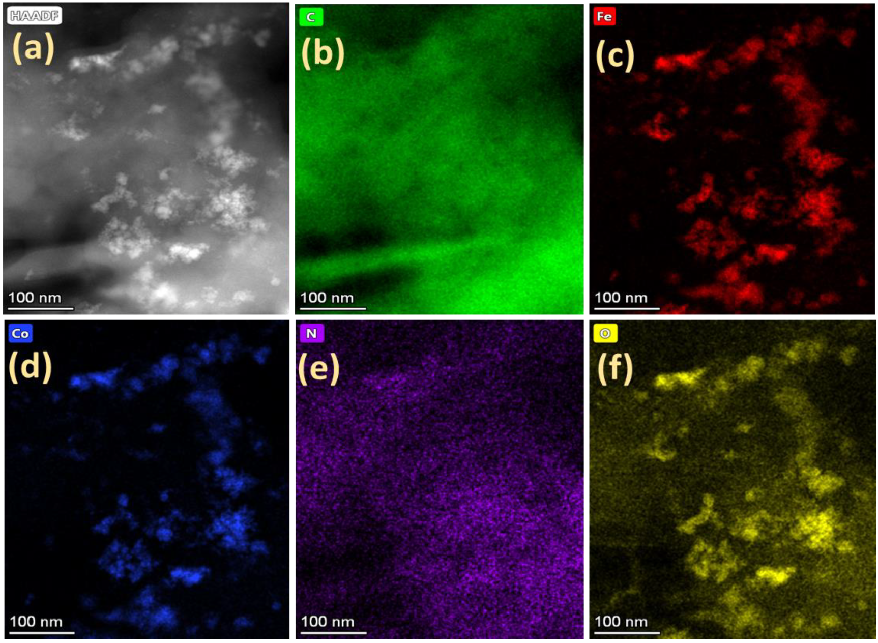
The phase contrast and elemental distribution of CoOx-Fe3O4/N-rGO can be seen from the HAADF-STEM images and STEM-EDS maps, respectively (Figure 2). The brighter contrast arose from the Co and Fe (Figure 2a) due to their higher atomic numbers compared to that of carbon. The particles were uniformly distributed with minor agglomeration. The STEM-EDS elemental maps of the C, Fe, Co, N, and O are shown in Figure 2b–f, respectively. Nitrogen was uniformly distributed throughout the carbon matrix (Figure 2b,e), as expected, from the catalyst synthesis procedure under NH4OH.
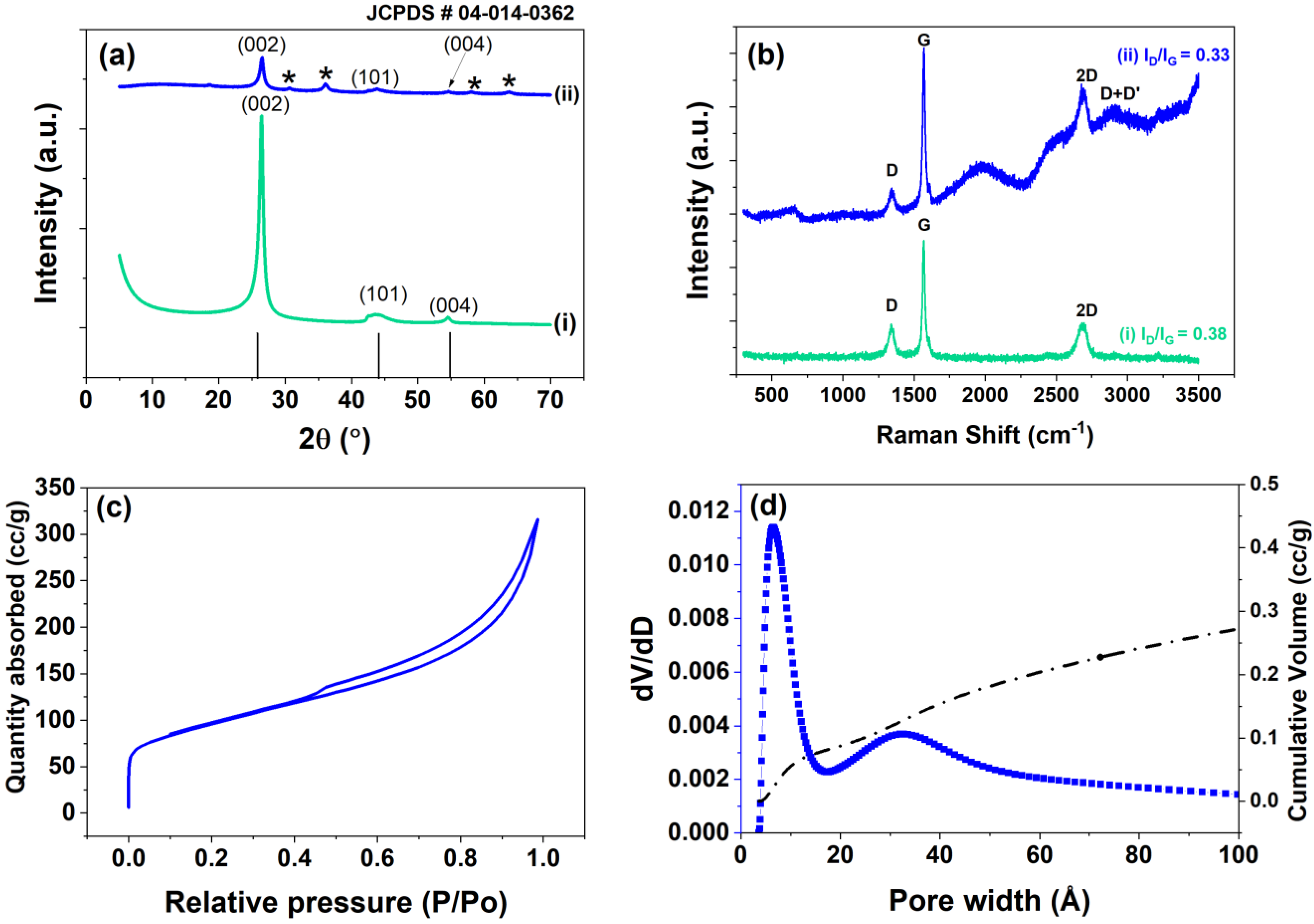
The XRD patterns of CoOx-Fe3O4/N-rGO and GO are shown in Figure 3a. The peaks at 2θ values of 26.3, 44.5, and 54.3° are typically assigned to the graphite (#04-014-0362) phase and correspond to reflection from (002), (101), and (004) planes. It is worth mentioning that the GO contained 4–10% edge-oxidized species; therefore, we did not observe the typical GO peak at ~10° [53]. The additional peaks at 2θ values of 30.6, 36.1, 58.2, and 68.3° observed with CoOx-Fe3O4/N-rGO are assigned to Co3O4 [35] and Fe3O4 [67] phases, respectively. The Raman spectra of both samples shown in Figure 3b show D, G, and 2D peaks. The D (1344 cm−1) and G (1570 cm−1) peaks are associated with the A1g breathing vibration of hexagonal sp2 carbon rings and E2g vibrations of sp2 carbon bonds. The 2D (2685 cm−1) peak is a second-order vibration of the D peak [68]. The additional peaks at 1983 and 2940 cm−1 (D+D’) could be observed with CoOx-Fe3O4/N-rGO. The broad Raman band at 1983 cm−1 may have been associated with the fluorescence signal [69] of the CoOx-Fe3O4/N-rGO after doping. The ID/IG ratios of 0.38 and 0.33 were for GO and CoOx-Fe3O4/N-rGO, respectively, suggesting that defects were not introduced after doping and the structure was preserved, signifying decoration. The N2-physisorption results for CoOx-Fe3O4/N-rGO are shown in Figure 3c,d, highlighting the isotherm, differential pore size distribution, and cumulative volume, respectively. CoOx-Fe3O4/N-rGO mainly exhibited micropores with a BET surface area of 338.90 m2 g−1, 1.46 times higher than the graphene oxide (GO). The numbers of graphene layers in the edge-oxidized GO and CoOx-Fe3O4/N-rGO were estimated to be 11 and 8, respectively, with a d-spacing of 0.34 nm, suggesting multilayers, as seen from the TEM images (Figure 1).
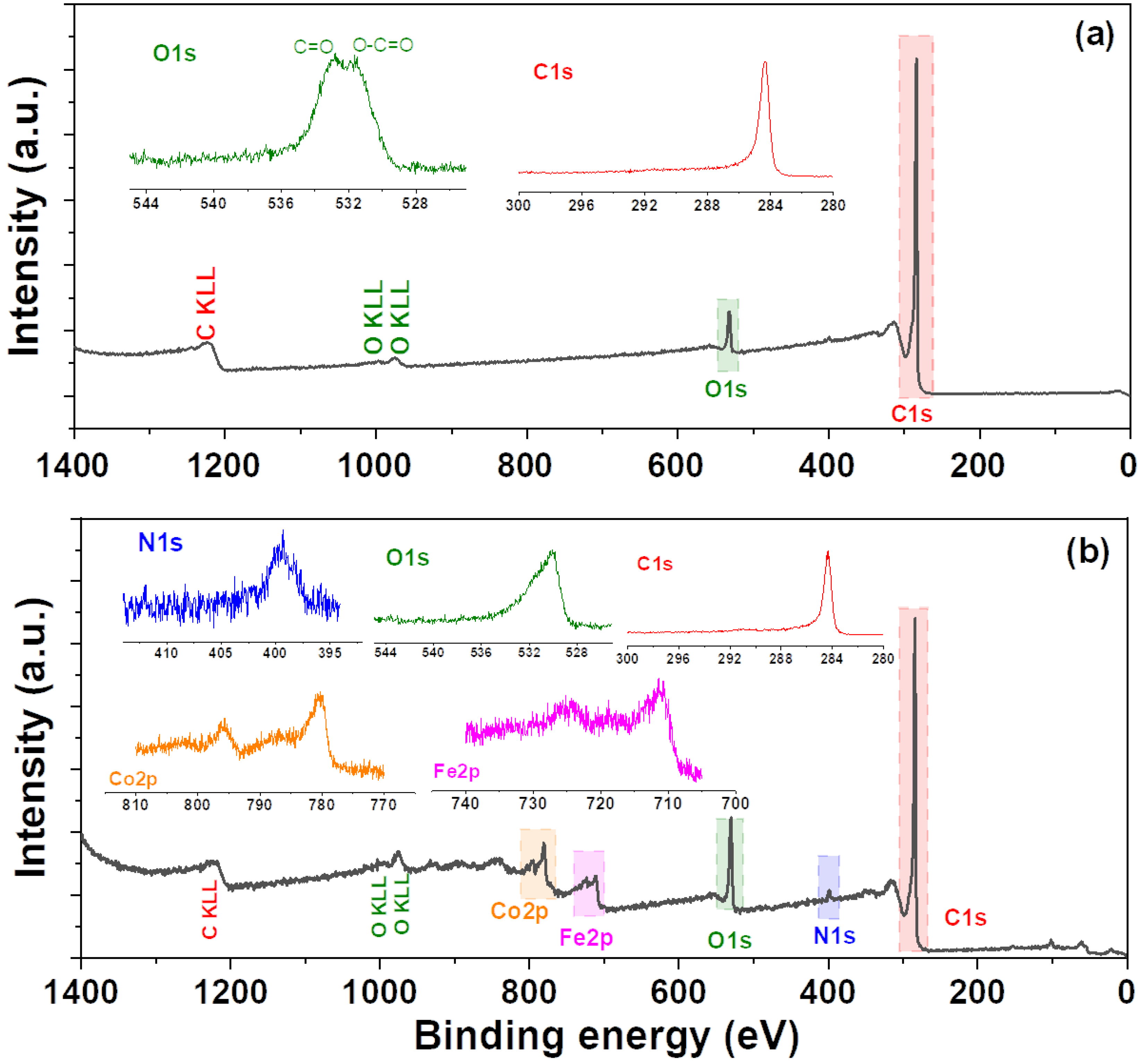
XPS survey spectra of GO and CoOx-Fe3O4/N-rGO are shown in Figure 4. The high-resolution elemental spectra are shown in the insets. XPS analysis revealed C, Co, Fe, O, and N in the CoOx-Fe3O4/N-rGO (Figure 4b) structure and C and O in pristine GO (Figure 4a). It was possible to determine the state of Fe as Fe3O4 according to the prominent Fe2p peak at 710.7 eV (Figure 4b inset). The Co:Fe metal atomic ratio was found to be 1:1 (Table 1). The N1s peak appeared to be regular organic C-N bonds that were not part of the sp2 structure found at ~398.3 eV for pyridine or ~401.0 eV for graphite [70]. The increase in the oxide content after the surface modification was attributed to the Fe and Co oxides, which were not present in the pristine GO. The oxygen content in CoOx-Fe3O4/N-rGO was 11.24%, which was 1.9 times higher than in the pristine GO (Table 1).
The overlaid ORR voltammograms of GO, Pt/C, and CoOx-Fe3O4/N-rGO with loadings of 0.15, 0.76, and 2.00 mg cm−2 are shown in Figure 5a. The onset potential of the ORR measured at 0.1 mA cm−2 was 0.80, 0.86, 0.89, 0.93, and 0.96 V for GO, CoOx-Fe3O4/N-rGO (0.15 mg cm−2), CoOx-Fe3O4/N-rGO (0.76 mg cm−2), CoOx-Fe3O4/N-rGO (2.00 mg cm−2), and Pt/C (0.013 mgPt cm−2), respectively. As expected, the performance of the catalyst was enhanced by increasing the loading from 0.15 to 0.76 and 2.00 mg cm−2. Only a minor improvement in the kinetic region was noticed, with an increase in loading from 0.76 to 2.00 mg cm−2 suggesting saturation of the ORR active sites, the increase in the limiting current density by a factor of ca. [email protected] V notwithstanding. The increase in the experimental limiting current could be attributable to the increase in the catalyst loading, as reported by Zhong et al. [71] and Chung et al. [72]. Furthermore, the ORR activity of CoOx-Fe3O4/N-rGO (2.00 mg cm−2) was within 20 [email protected] mA cm−2, with a ca. [email protected] V times increase in the limiting current compared to commercial Pt/C.
A significant 130 mV positive-shift in the ORR potential at −1.5 mA cm−2 was observed with CoOx-Fe3O4/N-rGO (2.00 mg cm−2) compared to GO itself. The ORR onset potential of CoOx-Fe3O4/N-rGO (0.76 mg cm−2) was 0.264 V higher than that for Co3O4/C reported by Troung et al., mainly due to the presence of Fe in our catalysts [48].
The corresponding peroxide generation current is shown in Figure 5b. The GO showed the highest H2O2 generation at all the potentials, while the Pt/C showed the lowest current, as expected. It was considered interesting to further analyze the peroxide generation behavior of these catalysts, which provided further information about the ORR.
On Pt/C, the peroxide current started at 0.85 V, which was followed by a maximum at 0.75 V, and increased further below 0.2 V due to surface blocking by hydrogen underpotential deposition (Hupd) [73]. The maximum at 0.75 V was attributed to the interaction between O2 and surface hydroxyl species on Pt [74]. On GO, the peroxide current onset started below 0.8 V and increased gradually up to 0.5 V and then decreased further due to the shift in the ORR mechanism from 2e to 4e transfer. For CoOx-Fe3O4/N-rGO, the peroxide generation was ~1.5 times lower than that of GO with the same loading. With an increase in the loading of CoOx-Fe3O4/N-rGO, the presence of increased Co and Fe sites helped to decrease the peroxide yield on the catalyst surface down to 0.4 V, and below this potential, the changes in H2O2 were insignificant. It is worth mentioning that peroxide generation on Co-based catalysts is reportedly higher than with Fe alone, and higher loading is needed to reduce the H2O2 yield [41].
We quantitatively analyzed the corresponding % H2O2 and the number of electrons transferred (n) (Figure 5c,d). The lowest % H2O2 and the corresponding highest n were calculated for Pt/C. On CoOx-Fe3O4/N-rGO, the % H2O2 decreased by a factor of ~3 compared to GO. As seen from the figure, with an increase in loading from 0.75 to 2.00 mg cm−2, the % H2O2 decreased gradually at all the potentials. The reverse trend was seen for n with higher loadings. Interestingly, n reached 3.9 @0.80 V for CoOx-Fe3O4/N-rGO (2.00 mg cm−2), matching commercial Pt/C, which suggested the dominance of the direct 4e ORR mechanism. The n value was higher in our work compared to that reported by Liang et al. for Co3O4/N-rmGO catalysts [35], suggesting an improved conversion efficiency for ORR. Furthermore, the inset in Figure 5d shows the 50 representative CV cycles of the CoOx-Fe3O4/N-rGO (2.00 mg cm−2) to highlight the surface electrochemical feature of the material.
To test the stability of the catalysts, we employed AST load cycles of CoOx-Fe3O4/N-rGO (2.00 mg cm−2) in O2 to mimic the fuel cell conditions, and the corresponding results are presented in Figure 5e. For comparison, we also employed AST load cycles on Pt/C (Figure 5f). The Co3O4-FeOx/N-rGO catalyst showed a negligible change in ORR performance (~2 mV) after 5000 AST load cycles in O2. The remarkable stability of the catalyst was attributed to the enhanced “tethering” due to the N doping [46,75] and was comparable to, and sometimes even higher than, the reported Fe-N-C catalysts in alkaline electrolytes [34,42]. Similarly, Pt/C showed a 22 mV decrease in the ORR potential at −3 mA cm−2 under the same AST conditions (Figure 5f).
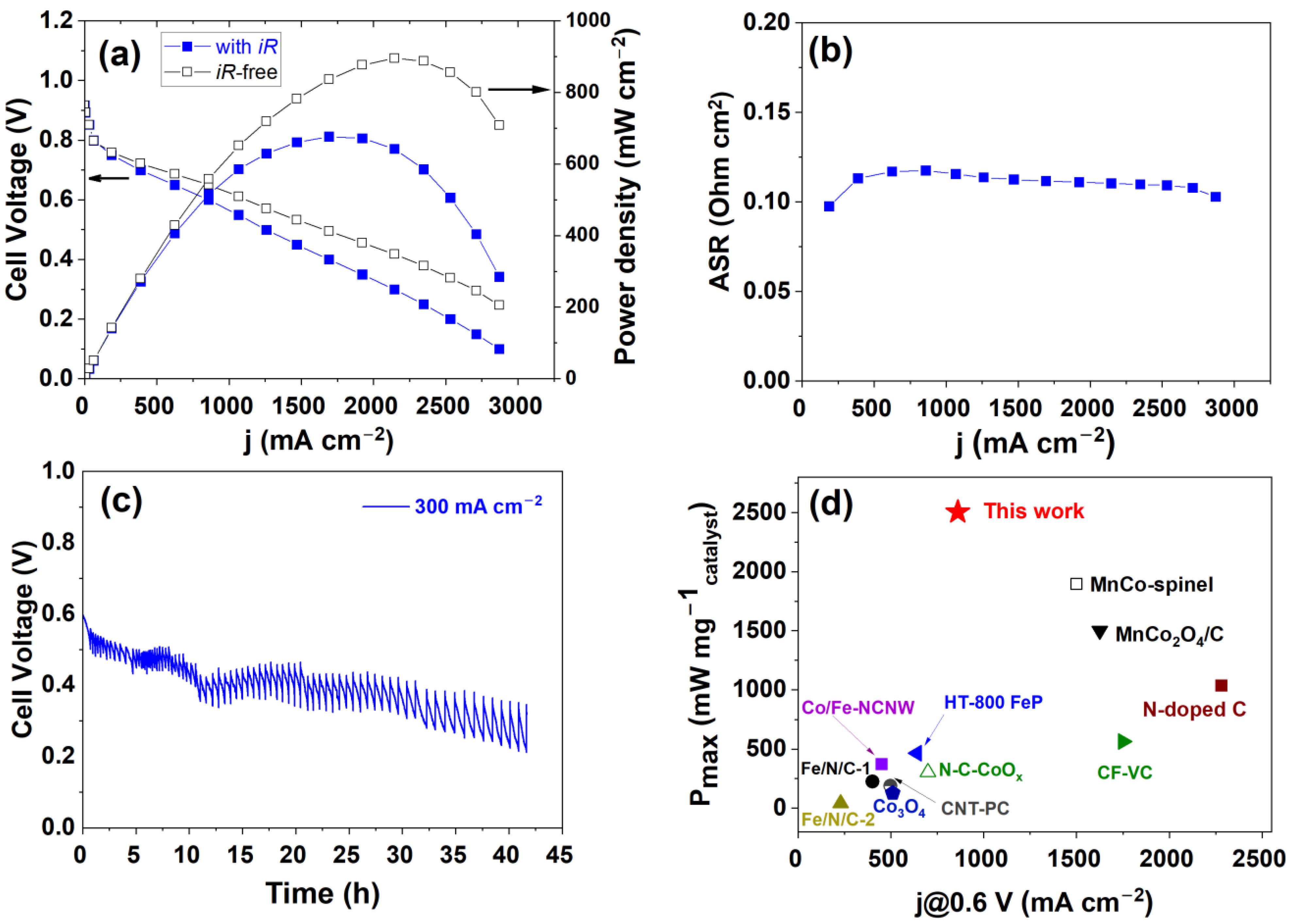
The performance of the CoOx-Fe3O4/N-rGO cathode catalyst was tested at 80 °C in an operando AEMFC, and the results are presented in Figure 6. The AEMFC made of the CoOx-Fe3O4/N-rGO cathode and PtRu/C anode achieved a peak power density of 676 mW cm−2 and a limiting current density of ca. 2900 mA cm−2 (Figure 6a). It should be noted that the corrected iR-free cell performance reached ca. 1 W cm−2. The area-specific resistance (ASR) remained constant at 0.12 Ω cm2 during cell polarization (Figure 6b), indicating stable operation. Moreover, we were able to further test the durability of the AEMFC for 42 h under a constant current density of 300 mA cm−2 (Figure 6c). It is also worth mentioning that a low loading (0.27 mg cm−2) for the Co3O4-FeOx/N-rGO catalyst was used in this polarization and longevity performance testing. Very few reports in the literature show the long-term durability of AEMFCs based on PGM-free catalysts [22,43]. The overall voltage decay of the AEMFC based on our CoOx-Fe3O4/N-rGO catalyst was ca. 5.6 mV h−1, which can be considered slightly higher than the state-of-the-art catalysts in operando conditions [43,76]. For instance, Peng et al. [43] reported a N-C-CoOx cathode that showed a voltage decay of 0.93 mV h−1 after 100 h at 65 °C. Adabi et al. reported high-performance Fe-N-C catalysts with a degradation rate of 0.46 mV h−1, which is the best-performing Fe-N-C AEMFC cathode to date [77]. Our group recently reported a single-atom-site Fe-N-C cathode catalyst with a degradation rate of 0.95 mV h−1, attributed to cathode ionomer degradation due to the low water content [76]. We believe such degradation was likely the culprit in this work due to the low water content at the cathode, and further optimization of the fuel cell will lead to better stability at the MEA level compared to what was achieved at the RDE level.
A respectable power density per catalyst mass value of 2504 mW mgcatalyst−1 was obtained in this work. To the best of our knowledge, this value is the highest reported for PGM-free cathode catalysts to date, as summarized in Table 2 and Figure 6d [33,38,39,40,43,48]. We postulate that the improvement in the AEMFC performance using CoOx-Fe3O4/N-rGO as a cathode catalyst can be attributed to the synergistic effects of (i) the high turnover frequency of the transition metals (Co and Fe) for ORR and (ii) the enhancement provided by N doping to the metal distribution and stability of the catalyst.
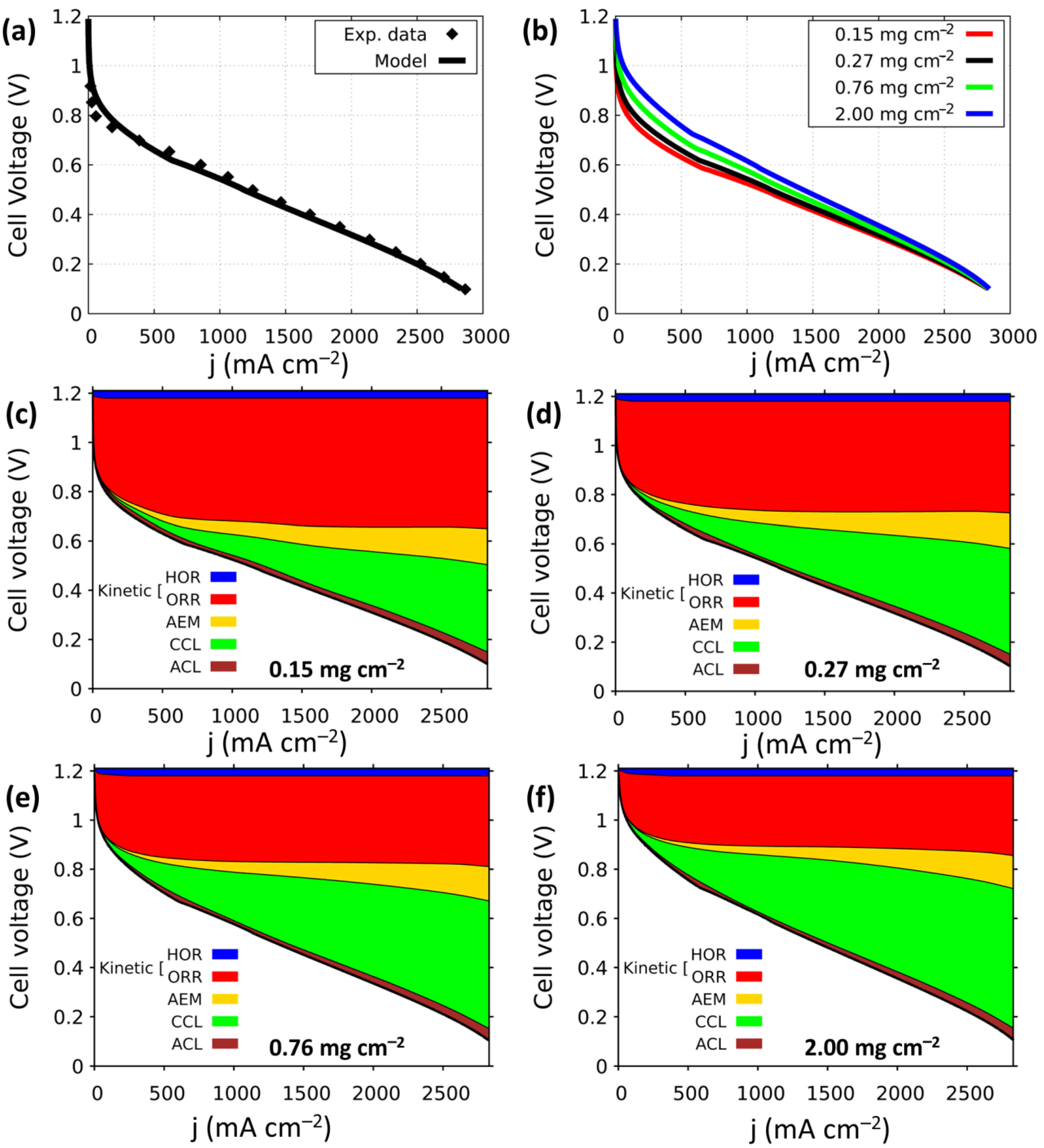
To further understand the impact of the catalyst loading on cell performance, we applied our one-dimensional model to validate the experimental results and calculate the individual contributions to the total cell overpotential. Figure 7a shows a comparison of the simulated and experimental polarization curves for AEMFCs with a cathode catalyst loading of 0.27 mg cm−2. Good agreement between the predicted and the measured data was found. Following that, we simulated the performance of AEMFCs with different cathode catalyst loadings ranging from 0.15 to 2.00 mg cm−2. As can be seen in the polarization curves in Figure 7b, increasing the cathode catalyst loading enhanced the kinetic region significantly, resulting in a higher current density. For instance, increasing the loading from 0.15 to 2.00 mg cm−2 improved the current density measured at 0.8 V from 80 to 400 mA cm−2. In order to quantitatively understand the effect of the loading on the behavior of the cell, we calculated the overpotential distribution of cell components across the MEA. Specifically, we simulated the kinetic losses due to HOR and ORR, transport through the AEM, and transport through the anode and cathode CLs (Figure 7c–f). The results showed that the ORR kinetics were for the primary source of losses in the cell for current density values below 1000 mA cm−2. This finding is quantitatively analyzed and presented in Table 3, which highlights the significant impact of ORR kinetics on the overall performance of the cell. Furthermore, the results presented in Figure 7c–f and Table 3 provide compelling evidence that increasing the loading from 0.15 to 2.00 mg cm−2 has a notable impact on the overpotential of the ORR. Specifically, the data demonstrate a significant reduction in overpotential from 470 to 272 mV, underscoring the critical role of loading in the performance of the cell. Interesting to note is the considerable voltage loss caused by the transport through the cathode catalyst layer. This can be explained by the increase in CL thickness as the catalyst loading increases. These findings are consistent with our recent study [66] on the role of the ionomer within the cathode CL, which revealed a significant contribution to total voltage losses. Since the same AEM was used in all cells, no change in voltage loss resulting from transport through the membrane could be observed. Similarly, the transport through the anode CL was independent of the changes in the cathode loading and, overall, very small, which was attributed mainly to the thin anode layer and high hydration levels [66,80], benefitting from the fast HOR kinetics.

4. Conclusions

We synthesized CoOx-Fe3O4/N-rGO using a scalable and reproducible hydrothermal method. The presence of Co, Fe, and N in the structure was verified with XPS and STEM-EDS mapping. The N2-physisorption results showed a 1.4 times increased BET surface area with doping as compared to graphene oxide. The GO structure was preserved, as shown by a similar ID/IG ratio of ~0.3. A promising ORR improvement of 130 [email protected] mA cm−2 was achieved compared to bare GO. The ORR performance of CoOx-Fe3O4/N-rGO after 5000 AST load cycles in O2 showed a negative shift of only 2 mV@-3 mA cm−2, ~11 times lower than standard Pt/C tested at the same conditions (22 mV). This proves the remarkable stability of the catalyst. The improved performance of the catalysts was mainly due to the synergistic effect of Co/Fe oxides, along with N doping in the carbon matrix. Finally, the H2-O2 operando AEMFC operated with this cathode catalyst showed a peak power density of 676 mW cm−2 and the highest power density per cathode catalyst mass value in the literature for PGM-free cathode AEMFCs. The fuel cell polarization curves were validated with an AEMFC model and the results showed a close resemblance to the experimental data. The deconvolution of the results was performed with various cathode catalyst loadings to quantify the losses in the catalyst layer. The kinetic losses decreased gradually with the increase in catalyst loading and, at the same time, the mass transport was inhibited due to the thick catalyst layer. Thus, the potential enhancing mechanisms for improving AEMFC performance using a CoOx-Fe3O4/N-rGO cathode can be attributed to the synergistic effects of (i) the high turnover frequency of transition metals (Co and Fe) for ORR and (ii) the enhancement provided by N doping to the metal distribution and stability of catalyst. Overall, the CoOx-Fe3O4/N-rGO catalyst exhibits very promising and high performance as a low-cost AEMFC cathode.

Author Contributions

R.K.S. and D.R.D. conceptualized the work. R.K.S. was responsible for synthesis, characterization, and electrochemical performance. J.C.D. and L.J. participated in the AEMFC tests. K.Y. and S.B. carried out AEMFC modeling and deconvolution. R.K.S. wrote the original draft, and it was edited by all the authors. All authors have read and agreed to the published version of the manuscript.

Funding

This research was partially funded by the Nancy and Stephen Grand Technion Energy Program (GTEP); the Russell Berrie Nanotechnology Institute, Technion; and the Israeli Science Foundation, grant number 169/22. R.K.S. acknowledges the support from the Vellore Institute of Technology (VIT), India, through VIT SEED Grant-RGEMS Fund (SG20220086). For their kind financial assistance in the form of the Jacobs Fellowship and the ISTRC Scholarship, respectively, J.C.D. personally thanks Irwin and Joan Jacobs, as well as the Israeli Smart Transportation Research Center. K.Y. thanks the Ministry of Science and Technology’s Zvi Yanai Fellowship for financial assistance.

Data Availability Statement

The data will be shared with request to the corresponding author.

Conflicts of Interest

The authors declare no conflict of interest.

References

  1. Dekel, D.R. Review of cell performance in anion exchange membrane fuel cells. J. Power Sources 2018, 375, 158–169. [Google Scholar] [CrossRef]
  2. Gottesfeld, S.; Dekel, D.R.; Page, M.; Bae, C.; Yan, Y.; Zelenay, P.; Kim, Y.S. Anion exchange membrane fuel cells: Current status and remaining challenges. J. Power Sources 2018, 375, 170–184. [Google Scholar] [CrossRef]
  3. Mustain, W.E.; Chatenet, M.; Page, M.; Kim, Y.S. Durability challenges of anion exchange membrane fuel cells. Energy Environ. Sci. 2020, 13, 2805–2838. [Google Scholar] [CrossRef]
  4. Ramaswamy, N.; Mukerjee, S. Alkaline Anion-Exchange Membrane Fuel Cells: Challenges in Electrocatalysis and Interfacial Charge Transfer. Chem. Rev. 2019, 119, 11945–11979. [Google Scholar] [CrossRef]
  5. Willdorf-Cohen, S.; Kaushansky, A.; Dekel, D.R.; Diesendruck, C.E. Hydroxide Chemoselectivity Changes with Water Microsolvation. J. Phys. Chem. Lett. 2022, 13, 10216–10221. [Google Scholar] [CrossRef] [PubMed]
  6. Liu, X.; Xie, N.; Xue, J.; Li, M.; Zheng, C.; Zhang, J.; Qin, Y.; Yin, Y.; Dekel, D.R.; Guiver, M.D. Magnetic-field-oriented mixed-valence-stabilized ferrocenium anion-exchange membranes for fuel cells. Nat. Energy 2022, 7, 329–339. [Google Scholar] [CrossRef]
  7. Mandal, M.; Huang, G.; Hassan, N.U.; Peng, X.; Gu, T.; Brooks-Starks, A.H.; Bahar, B.; Mustain, W.E.; Kohl, P.A. The Importance of Water Transport in High Conductivity and High-Power Alkaline Fuel Cells. J. Electrochem. Soc. 2020, 167, 054501. [Google Scholar] [CrossRef]
  8. Wang, J.; Zhao, Y.; Setzler, B.P.; Rojas-Carbonell, S.; Ben Yehuda, C.; Amel, A.; Page, M.; Wang, L.; Hu, K.; Shi, L.; et al. Poly(aryl piperidinium) membranes and ionomers for hydroxide exchange membrane fuel cells. Nat. Energy 2019, 4, 392–398. [Google Scholar] [CrossRef]
  9. Wang, L.; Peng, X.; Mustain, W.E.; Varcoe, J.R. Radiation-grafted anion-exchange membranes: The switch from low- to high-density polyethylene leads to remarkably enhanced fuel cell performance. Energy Environ. Sci. 2019, 12, 1575–1579. [Google Scholar] [CrossRef] [Green Version]
  10. Fan, J.; Willdorf-Cohen, S.; Schibli, E.M.; Paula, Z.; Li, W.; Skalski, T.J.G.; Sergeenko, A.T.; Hohenadel, A.; Frisken, B.J.; Magliocca, E.; et al. Poly(bis-arylimidazoliums) possessing high hydroxide ion exchange capacity and high alkaline stability. Nat. Commun. 2019, 10, 2306. [Google Scholar] [CrossRef] [Green Version]
  11. Pham, T.H.; Olsson, J.S.; Jannasch, P. N-Spirocyclic Quaternary Ammonium Ionenes for Anion-Exchange Membranes. J. Am. Chem. Soc. 2017, 139, 2888–2891. [Google Scholar] [CrossRef] [PubMed]
  12. Gonçalves Biancolli, A.L.; Herranz, D.; Wang, L.; Stehlíková, G.; Bance-Soualhi, R.; Ponce-González, J.; Ocón, P.; Ticianelli, E.A.; Whelligan, D.K.; Varcoe, J.R.; et al. ETFE-based anion-exchange membrane ionomer powders for alkaline membrane fuel cells: A first performance comparison of head-group chemistry. J. Mater. Chem. A 2018, 6, 24330–24341. [Google Scholar] [CrossRef] [Green Version]
  13. Aggarwal, K.; Gjineci, N.; Kaushansky, A.; Bsoul, S.; Douglin, J.C.; Li, S.; Salam, I.; Aharonovich, S.; Varcoe, J.R.; Dekel, D.R.; et al. Isoindolinium Groups as Stable Anion Conductors for Anion-Exchange Membrane Fuel Cells and Electrolyzers. ACS Mater. Au 2022, 2, 367–373. [Google Scholar] [CrossRef]
  14. Yassin, K.; Douglin, J.C.; Rasin, I.G.; Santori, P.G.; Eriksson, B.; Bibent, N.; Jaouen, F.; Brandon, S.; Dekel, D.R. The effect of membrane thickness on AEMFC Performance: An integrated theoretical and experimental study. Energy Convers. Manag. 2022, 270, 116203. [Google Scholar] [CrossRef]
  15. Omasta, T.J.; Park, A.M.; LaManna, J.M.; Zhang, Y.; Peng, X.; Wang, L.; Jacobson, D.L.; Varcoe, J.R.; Hussey, D.S.; Pivovar, B.S.; et al. Beyond catalysis and membranes: Visualizing and solving the challenge of electrode water accumulation and flooding in AEMFCs. Energy Environ. Sci. 2018, 11, 551–558. [Google Scholar] [CrossRef] [Green Version]
  16. Zhang, B.; Hua, Y.; Gao, Z. Strategies to optimize water management in anion exchange membrane fuel cells. J. Power Sources 2022, 525, 231141. [Google Scholar] [CrossRef]
  17. Xue, Y.; Shi, L.; Liu, X.; Fang, J.; Wang, X.; Setzler, B.P.; Zhu, W.; Yan, Y.; Zhuang, Z. A highly-active, stable and low-cost platinum-free anode catalyst based on RuNi for hydroxide exchange membrane fuel cells. Nat. Commun. 2020, 11, 5651. [Google Scholar] [CrossRef]
  18. Wang, R.; Li, D.; Maurya, S.; Kim, Y.S.; Wu, Y.; Liu, Y.; Strmcnik, D.; Markovic, N.M.; Stamenkovic, V.R. Ultrafine Pt cluster and RuO2 heterojunction anode catalysts designed for ultra-low Pt-loading anion exchange membrane fuel cells. Nanoscale Horiz. 2020, 5, 316–324. [Google Scholar] [CrossRef]
  19. Miller, H.A.; Bellini, M.; Dekel, D.R.; Vizza, F. Recent developments in Pd-CeO2 nano-composite electrocatalysts for anodic reactions in anion exchange membrane fuel cells. Electrochem. Commun. 2022, 135, 107219. [Google Scholar] [CrossRef]
  20. Kumar, Y.; Kibena-Põldsepp, E.; Kozlova, J.; Rähn, M.; Treshchalov, A.; Kikas, A.; Kisand, V.; Aruväli, J.; Tamm, A.; Douglin, J.C.; et al. Bifunctional Oxygen Electrocatalysis on Mixed Metal Phthalocyanine-Modified Carbon Nanotubes Prepared via Pyrolysis. ACS Appl. Mater. Interfaces 2021, 13, 41507–41516. [Google Scholar] [CrossRef]
  21. Zhu, W.; Pei, Y.; Douglin, J.C.; Zhang, J.; Zhao, H.; Xue, J.; Wang, Q.; Li, R.; Qin, Y.; Yin, Y.; et al. Multi-scale study on bifunctional Co/Fe–N–C cathode catalyst layers with high active site density for the oxygen reduction reaction. Appl. Catal. B Environ. 2021, 299, 120656. [Google Scholar] [CrossRef]
  22. Douglin, J.C.; Singh, R.K.; Haj-Bsoul, S.; Li, S.; Biemolt, J.; Yan, N.; Varcoe, J.R.; Rothenberg, G.; Dekel, D.R. A high-temperature anion-exchange membrane fuel cell with a critical raw material-free cathode. Chem. Eng. J. Adv. 2021, 8, 100153. [Google Scholar] [CrossRef]
  23. Zion, N.; Douglin, J.C.; Cullen, D.A.; Zelenay, P.; Dekel, D.R.; Elbaz, L. Porphyrin Aerogel Catalysts for Oxygen Reduction Reaction in Anion-Exchange Membrane Fuel Cells. Adv. Funct. Mater. 2021, 31, 2100963. [Google Scholar] [CrossRef]
  24. Lilloja, J.; Kibena-Põldsepp, E.; Sarapuu, A.; Douglin, J.C.; Käärik, M.; Kozlova, J.; Paiste, P.; Kikas, A.; Aruväli, J.; Leis, J.; et al. Transition-Metal- and Nitrogen-Doped Carbide-Derived Carbon/Carbon Nanotube Composites as Cathode Catalysts for Anion-Exchange Membrane Fuel Cells. ACS Catal. 2021, 11, 1920–1931. [Google Scholar] [CrossRef]
  25. Li, Q.; Peng, H.; Wang, Y.; Xiao, L.; Lu, J.; Zhuang, L. The Comparability of Pt to Pt-Ru in Catalyzing the Hydrogen Oxidation Reaction for Alkaline Polymer Electrolyte Fuel Cells Operated at 80 °C. Angew. Chem. Int. Ed. 2019, 58, 1442–1446. [Google Scholar] [CrossRef]
  26. Cong, Y.; Yi, B.; Song, Y. Hydrogen oxidation reaction in alkaline media: From mechanism to recent electrocatalysts. Nano Energy 2018, 44, 288–303. [Google Scholar] [CrossRef]
  27. Davydova, E.S.; Mukerjee, S.; Jaouen, F.; Dekel, D.R. Electrocatalysts for Hydrogen Oxidation Reaction in Alkaline Electrolytes. ACS Catal. 2018, 8, 6665–6690. [Google Scholar] [CrossRef]
  28. Zhuang, Z.; Giles, S.A.; Zheng, J.; Jenness, G.R.; Caratzoulas, S.; Vlachos, D.G.; Yan, Y. Nickel supported on nitrogen-doped carbon nanotubes as hydrogen oxidation reaction catalyst in alkaline electrolyte. Nat. Commun. 2016, 7, 10141. [Google Scholar] [CrossRef] [Green Version]
  29. Speck, F.D.; Ali, F.S.M.; Paul, M.T.Y.; Singh, R.K.; Böhm, T.; Hofer, A.; Kasian, O.; Thiele, S.; Bachmann, J.; Dekel, D.R.; et al. On the Improved Hydrogen Oxidation Reaction Activity and Stability of Buried Metal-Oxide Electrocatalyst Interfaces. Chem. Mater. 2020, 32, 7716–7724. [Google Scholar] [CrossRef]
  30. Miller, H.A.; Lavacchi, A.; Vizza, F.; Marelli, M.; Di Benedetto, F.; D’Acapito, F.; Paska, Y.; Page, M.; Dekel, D.R. A Pd/C-CeO2 Anode Catalyst for High-Performance Platinum-Free Anion Exchange Membrane Fuel Cells. Angew. Chem. Int. Ed. 2016, 55, 6004–6007. [Google Scholar] [CrossRef]
  31. Zhou, Y.; Xie, Z.; Jiang, J.; Wang, J.; Song, X.; He, Q.; Ding, W.; Wei, Z. Lattice-confined Ru clusters with high CO tolerance and activity for the hydrogen oxidation reaction. Nat. Catal. 2020, 3, 454–462. [Google Scholar] [CrossRef]
  32. Pagliaro, M.V.; Wen, C.; Sa, B.; Liu, B.; Bellini, M.; Bartoli, F.; Sahoo, S.; Singh, R.K.; Alpay, S.P.; Miller, H.A.; et al. Improving Alkaline Hydrogen Oxidation Activity of Palladium through Interactions with Transition-Metal Oxides. ACS Catal. 2022, 12, 10894–10904. [Google Scholar] [CrossRef]
  33. Li, J.-C.; Maurya, S.; Kim, Y.S.; Li, T.; Wang, L.; Shi, Q.; Liu, D.; Feng, S.; Lin, Y.; Shao, M. Stabilizing Single-Atom Iron Electrocatalysts for Oxygen Reduction via Ceria Confining and Trapping. ACS Catal. 2020, 10, 2452–2458. [Google Scholar] [CrossRef]
  34. Mohan, R.; Modak, A.; Schechter, A. NH3-Plasma pre-treated carbon supported active iron–nitrogen catalyst for oxygen reduction in acid and alkaline electrolytes. Catal. Sci. Technol. 2020, 10, 1675–1687. [Google Scholar] [CrossRef]
  35. Liang, Y.; Li, Y.; Wang, H.; Zhou, J.; Wang, J.; Regier, T.; Dai, H. Co3O4 nanocrystals on graphene as a synergistic catalyst for oxygen reduction reaction. Nat. Mater. 2011, 10, 780–786. [Google Scholar] [CrossRef] [Green Version]
  36. Firouzjaie, H.A.; Mustain, W.E. Catalytic Advantages, Challenges, and Priorities in Alkaline Membrane Fuel Cells. ACS Catal. 2020, 10, 225–234. [Google Scholar] [CrossRef] [Green Version]
  37. Kisand, K.; Sarapuu, A.; Douglin, J.C.; Kikas, A.; Treshchalov, A.; Käärik, M.; Piirsoo, H.-M.; Paiste, P.; Aruväli, J.; Leis, J.; et al. Templated Nitrogen-, Iron-, and Cobalt-Doped Mesoporous Nanocarbon Derived from an Alkylresorcinol Mixture for Anion-Exchange Membrane Fuel Cell Application. ACS Catal. 2022, 12, 14050–14061. [Google Scholar] [CrossRef]
  38. Ren, H.; Wang, Y.; Yang, Y.; Tang, X.; Peng, Y.; Peng, H.; Xiao, L.; Lu, J.; Abruña, H.D.; Zhuang, L. Fe/N/C Nanotubes with Atomic Fe Sites: A Highly Active Cathode Catalyst for Alkaline Polymer Electrolyte Fuel Cells. ACS Catal. 2017, 7, 6485–6492. [Google Scholar] [CrossRef]
  39. Sa, Y.J.; Seo, D.-J.; Woo, J.; Lim, J.T.; Cheon, J.Y.; Yang, S.Y.; Lee, J.M.; Kang, D.; Shin, T.J.; Shin, H.S.; et al. A General Approach to Preferential Formation of Active Fe–Nx Sites in Fe–N/C Electrocatalysts for Efficient Oxygen Reduction Reaction. J. Am. Chem. Soc. 2016, 138, 15046–15056. [Google Scholar] [CrossRef]
  40. Hossen, M.; Artyushkova, K.; Atanassov, P.; Serov, A. Synthesis and characterization of high performing Fe-N-C catalyst for oxygen reduction reaction (ORR) in Alkaline Exchange Membrane Fuel Cells. J. Power Sources 2018, 375, 214–221. [Google Scholar] [CrossRef]
  41. Sun, Y.; Silvioli, L.; Sahraie, N.R.; Ju, W.; Li, J.; Zitolo, A.; Li, S.; Bagger, A.; Arnarson, L.; Wang, X.; et al. Activity–Selectivity Trends in the Electrochemical Production of Hydrogen Peroxide over Single-Site Metal–Nitrogen–Carbon Catalysts. J. Am. Chem. Soc. 2019, 141, 12372–12381. [Google Scholar] [CrossRef] [PubMed]
  42. Santori, P.G.; Speck, F.D.; Li, J.; Zitolo, A.; Jia, Q.; Mukerjee, S.; Cherevko, S.; Jaouen, F. Effect of pyrolysis atmosphere and electrolyte pH on the oxygen reduction activity, stability and spectroscopic signature of FeNx moieties in Fe-NC catalysts. J. Electrochem. Soc. 2019, 166, F3311–F3320. [Google Scholar] [CrossRef]
  43. Peng, X.; Omasta, T.J.; Magliocca, E.; Wang, L.; Varcoe, J.R.; Mustain, W.E. Nitrogen-doped Carbon–CoOx Nanohybrids: A Precious Metal Free Cathode that Exceeds 1.0 W cm−2 Peak Power and 100 h Life in Anion-Exchange Membrane Fuel Cells. Angew. Chem. Int. Ed. 2019, 58, 1046–1051. [Google Scholar] [CrossRef] [PubMed] [Green Version]
  44. Xiong, Y.; Yang, Y.; Feng, X.; DiSalvo, F.J.; Abruña, H.D. A Strategy for Increasing the Efficiency of the Oxygen Reduction Reaction in Mn-Doped Cobalt Ferrites. J. Am. Chem. Soc. 2019, 141, 4412–4421. [Google Scholar] [CrossRef]
  45. Jaouen, F.; Proietti, E.; Lefèvre, M.; Chenitz, R.; Dodelet, J.-P.; Wu, G.; Chung, H.T.; Johnston, C.M.; Zelenay, P. Recent advances in non-precious metal catalysis for oxygen-reduction reaction in polymer electrolyte fuel cells. Energy Environ. Sci. 2011, 4, 114–130. [Google Scholar] [CrossRef]
  46. Zhou, Y.; Neyerlin, K.; Olson, T.S.; Pylypenko, S.; Bult, J.; Dinh, H.N.; Gennett, T.; Shao, Z.; O’Hayre, R. Enhancement of Pt and Pt-alloy fuel cell catalyst activity and durability via nitrogen-modified carbon supports. Energy Environ. Sci. 2010, 3, 1437–1446. [Google Scholar] [CrossRef]
  47. Yang, Y.; Peng, H.; Xiong, Y.; Li, Q.; Lu, J.; Xiao, L.; DiSalvo, F.J.; Zhuang, L.; Abruña, H.D. High-Loading Composition-Tolerant Co–Mn Spinel Oxides with Performance beyond 1 W/cm2 in Alkaline Polymer Electrolyte Fuel Cells. ACS Energy Lett. 2019, 4, 1251–1257. [Google Scholar] [CrossRef]
  48. Truong, V.M.; Tolchard, J.R.; Svendby, J.; Manikandan, M.; Miller, H.A.; Sunde, S.; Yang, H.; Dekel, D.R.; Barnett, A.O. Platinum and Platinum Group Metal-Free Catalysts for Anion Exchange Membrane Fuel Cells. Energies 2020, 13, 582. [Google Scholar] [CrossRef] [Green Version]
  49. Chung, H.T.; Cullen, D.A.; Higgins, D.; Sneed, B.T.; Holby, E.F.; More, K.L.; Zelenay, P. Direct atomic-level insight into the active sites of a high-performance PGM-free ORR catalyst. Science 2017, 357, 479–484. [Google Scholar] [CrossRef] [Green Version]
  50. Bashyam, R.; Zelenay, P. A class of non-precious metal composite catalysts for fuel cells. Nature 2006, 443, 63–66. [Google Scholar] [CrossRef]
  51. Wu, G.; More, K.L.; Johnston, C.M.; Zelenay, P. High-performance electrocatalysts for oxygen reduction derived from polyaniline, iron, and cobalt. Science 2011, 332, 443–447. [Google Scholar] [CrossRef] [Green Version]
  52. Wang, L.; Brink, J.J.; Liu, Y.; Herring, A.M.; Ponce-González, J.; Whelligan, D.K.; Varcoe, J.R. Non-fluorinated pre-irradiation-grafted (peroxidated) LDPE-based anion-exchange membranes with high performance and stability. Energy Environ. Sci. 2017, 10, 2154–2167. [Google Scholar] [CrossRef] [Green Version]
  53. Kar, T.; Devivaraprasad, R.; Singh, R.K.; Bera, B.; Neergat, M. Reduction of graphene oxide—A comprehensive electrochemical investigation in alkaline and acidic electrolytes. RSC Adv. 2014, 4, 57781–57790. [Google Scholar] [CrossRef]
  54. Singh, R.K.; Davydova, E.S.; Douglin, J.; Godoy, A.O.; Tan, H.; Bellini, M.; Allen, B.J.; Jankovic, J.; Miller, H.A.; Alba-Rubio, A.C.; et al. Synthesis of CeOx-Decorated Pd/C Catalysts by Controlled Surface Reactions for Hydrogen Oxidation in Anion Exchange Membrane Fuel Cells. Adv. Funct. Mater. 2020, 30, 2002087. [Google Scholar] [CrossRef]
  55. Hamo, E.R.; Singh, R.K.; Douglin, J.C.; Chen, S.; Hassine, M.B.; Carbo-Argibay, E.; Lu, S.; Wang, H.; Ferreira, P.J.; Rosen, B.A.; et al. Carbide-Supported PtRu Catalysts for Hydrogen Oxidation Reaction in Alkaline Electrolyte. ACS Catal. 2021, 11, 932–947. [Google Scholar] [CrossRef]
  56. Gong, K.; Du, F.; Xia, Z.; Durstock, M.; Dai, L. Nitrogen-Doped Carbon Nanotube Arrays with High Electrocatalytic Activity for Oxygen Reduction. Science 2009, 323, 760–764. [Google Scholar] [CrossRef] [Green Version]
  57. Paulus, U.A.; Schmidt, T.J.; Gasteiger, H.A.; Behm, R.J. Oxygen reduction on a high-surface area Pt/Vulcan carbon catalyst: A thin-film rotating ring-disk electrode study. J. Electroanal. Chem. 2001, 495, 134–145. [Google Scholar] [CrossRef]
  58. Douglin, J.C.; Singh, R.K.; Hamo, E.R.; Hassine, M.B.; Ferreira, P.J.; Rosen, B.A.; Miller, H.A.; Rothenberg, G.; Dekel, D.R. Performance optimization of PGM and PGM-free catalysts in anion-exchange membrane fuel cells. J. Solid State Electrochem. 2022, 26, 2049–2057. [Google Scholar] [CrossRef]
  59. Praats, R.; Käärik, M.; Kikas, A.; Kisand, V.; Aruväli, J.; Paiste, P.; Merisalu, M.; Leis, J.; Sammelselg, V.; Zagal, J.H.; et al. Tammeveski, Electrocatalytic oxygen reduction reaction on iron phthalocyanine-modified carbide-derived carbon/carbon nanotube composite electrocatalysts. Electrochim. Acta 2020, 334, 135575. [Google Scholar] [CrossRef]
  60. Wierzbicki, S.; Douglin, J.C.; Singh, R.K.; Dekel, D.R.; Kruczała, K. Operando EPR Study of Radical Formation in Anion-Exchange Membrane Fuel Cells. ACS Catal. 2023, 13, 2744–2750. [Google Scholar] [CrossRef]
  61. Hassan, N.U.; Mandal, M.; Huang, G.; Firouzjaie, H.A.; Kohl, P.A.; Mustain, W.E. Achieving High-Performance and 2000 h Stability in Anion Exchange Membrane Fuel Cells by Manipulating Ionomer Properties and Electrode Optimization. Adv. Energy Mater. 2020, 10, 2001986. [Google Scholar] [CrossRef]
  62. Gasteiger, H.A.; Panels, J.E.; Yan, S.G. Dependence of PEM fuel cell performance on catalyst loading. J. Power Sources 2004, 127, 162–171. [Google Scholar] [CrossRef]
  63. Omasta, T.J.; Peng, X.; Miller, H.A.; Vizza, F.; Wang, L.; Varcoe, J.R.; Dekel, D.R.; Mustain, W.E. Beyond 1.0 W cm−2Performance without Platinum: The Beginning of a New Era in Anion Exchange Membrane Fuel Cells. J. Electrochem. Soc. 2018, 165, J3039–J3044. [Google Scholar] [CrossRef]
  64. Dekel, D.R.; Rasin, I.G.; Page, M.; Brandon, S. Steady state and transient simulation of anion exchange membrane fuel cells. J. Power Sources 2018, 375, 191–204. [Google Scholar] [CrossRef]
  65. Dekel, D.R.; Rasin, I.G.; Brandon, S. Predicting performance stability of anion exchange membrane fuel cells. J. Power Sources 2019, 420, 118–123. [Google Scholar] [CrossRef]
  66. Yassin, K.; Rasin, I.G.; Brandon, S.; Dekel, D.R. Elucidating the role of anion-exchange ionomer conductivity within the cathode catalytic layer of anion-exchange membrane fuel cells. J. Power Sources 2022, 524, 231083. [Google Scholar] [CrossRef]
  67. Shi, F.; Li, Y.; Zhang, Q.; Wang, H. Synthesis of Fe3O4/C/TiO2 Magnetic Photocatalyst via Vapor Phase Hydrolysis. Int. J. Photoenergy 2012, 2012, 365401. [Google Scholar] [CrossRef] [Green Version]
  68. Iqbal, M.W.; Singh, A.K.; Iqbal, M.Z.; Eom, J. Raman fingerprint of doping due to metal adsorbates on graphene. J. Phys. Condens. Matter. 2012, 24, 335301. [Google Scholar] [CrossRef]
  69. Xie, L.; Ling, X.; Fang, Y.; Zhang, J.; Liu, Z. Graphene as a Substrate To Suppress Fluorescence in Resonance Raman Spectroscopy. J. Am. Chem. Soc. 2009, 131, 9890–9891. [Google Scholar] [CrossRef]
  70. Kondo, T.; Guo, D.; Shikano, T.; Suzuki, T.; Sakurai, M.; Okada, S.; Nakamura, J. Observation of Landau levels on nitrogen-doped flat graphite surfaces without external magnetic fields. Sci. Rep. 2015, 5, 16412. [Google Scholar] [CrossRef] [Green Version]
  71. Zhong, G.; Xu, S.; Liu, L.; Zheng, C.Z.; Dou, J.; Wang, F.; Fu, X.; Liao, W.; Wang, H. Effect of experimental operations on the limiting current density of oxygen reduction reaction evaluated by rotating-disk electrode. ChemElectroChem 2020, 7, 1107–1114. [Google Scholar] [CrossRef]
  72. Chung, H.T.; Won, J.H.; Zelenay, P. Active and stable carbon nanotube/nanoparticle composite electrocatalyst for oxygen reduction. Nat. Commun. 2013, 4, 1922. [Google Scholar] [CrossRef] [Green Version]
  73. Neergat, M.; Gunasekar, V.; Singh, R.K. Oxygen reduction reaction and peroxide generation on Ir, Rh, and their selenides—A comparison with Pt and RuSe. J. Electrochem. Soc. 2011, 158, B1060. [Google Scholar] [CrossRef]
  74. Ramaswamy, N.; Mukerjee, S. Fundamental Mechanistic Understanding of Electrocatalysis of Oxygen Reduction on Pt and Non-Pt Surfaces: Acid versus Alkaline Media. Adv. Phys. Chem. 2012, 2012, 491604. [Google Scholar] [CrossRef] [Green Version]
  75. Pylypenko, S.; Queen, A.; Neyerlin, K.C.; Olson, T.; Dameron, A.; O’Neill, K.; Ginley, D.; Gorman, B.; Kocha, S.; Dinh, H.N.; et al. The Role of Nitrogen Doping on Durability in the Pt-Ru/HOPG System. ECS Trans. 2010, 33, 351–357. [Google Scholar] [CrossRef]
  76. Adabi, H.; Santori, P.G.; Shakouri, A.; Peng, X.; Yassin, K.; Rasin, I.G.; Brandon, S.; Dekel, D.R.; Hassan, N.U.; Sougrati, M.-T.; et al. Understanding how single-atom site density drives the performance and durability of PGM-free Fe–N–C cathodes in anion exchange membrane fuel cells. Mater. Today Adv. 2021, 12, 100179. [Google Scholar] [CrossRef]
  77. Adabi, H.; Shakouri, A.; Hassan, N.U.; Varcoe, J.R.; Zulevi, B.; Serov, A.; Regalbuto, J.R.; Mustain, W.E. High-performing commercial Fe–N–C cathode electrocatalyst for anion-exchange membrane fuel cells. Nat. Energy 2021, 6, 834–843. [Google Scholar] [CrossRef]
  78. Peng, X.; Kashyap, V.; Ng, B.; Kurungot, S.; Wang, L.; Varcoe, J.R.; Mustain, W.E. High-performing pgm-free aemfc cathodes from carbon-supported cobalt ferrite nanoparticles. Catalysts 2019, 9, 264. [Google Scholar] [CrossRef] [Green Version]
  79. Wang, Y.; Yang, Y.; Jia, S.; Wang, X.; Lyu, K.; Peng, Y.; Zheng, H.; Wei, X.; Ren, H.; Xiao, L.; et al. Synergistic Mn-Co catalyst outperforms Pt on high-rate oxygen reduction for alkaline polymer electrolyte fuel cells. Nat. Commun. 2019, 10, 1506. [Google Scholar] [CrossRef] [Green Version]
  80. Yassin, K.; Rasin, I.G.; Brandon, S.; Dekel, D.R. Quantifying the critical effect of water diffusivity in anion exchange membranes for fuel cell applications. J. Memb. Sci. 2020, 608, 118206. [Google Scholar] [CrossRef]
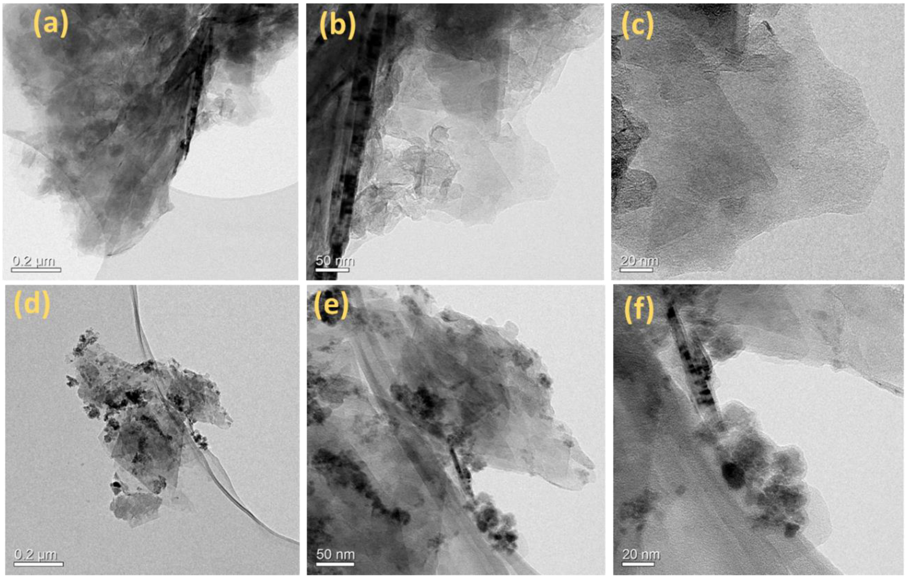
Figure 1. TEM images of GO (ac) and CoOx-Fe3O4/N-rGO (df). Scale bars are 0.2 µm (a,d), 50 nm (b,e), and 20 nm (c,f).
Energies 16 03425 g001
Figure 2. HAADF images of CoOx-Fe3O4/N-rGO (a). The corresponding STEM-EDS elemental maps of C (b), Fe (c), Co (d), N (e), and O (f).
Energies 16 03425 g002
Figure 3. XRD patterns of edge-oxidized GO (i) and CoOx-Fe3O4/N-rGO (ii) (a), Raman spectra of GO (i) and CoOx-Fe3O4/N-rGO (ii), * symbols indicate where the peaks arise from Fe2O3 and Co3O4. (b), N2 adsorption–desorption isotherm (c), and pore size distribution as a function of pore diameter for CoOx-Fe3O4/N-rGO, where dV/dD is the differential pore volume distribution (d).
Energies 16 03425 g003
Figure 4. Summarized XPS analysis of GO (a) and CoOx-Fe3O4/N-rGO (b). Insets show the high-resolution elemental scans.
Energies 16 03425 g004
Figure 5. ORR voltammograms of CoOx-Fe3O4/N-rGO with varied loadings of 0.15, 0.76, and 2.00 mg cm−2; GO (0.15 mg cm−2); and Pt/C (0.013 mgPt cm−2) (a); the corresponding H2O2 generation (b); the corresponding % H2O2 (c); the number of electrons transferred for ORR (d); 50 representative CVs of CoOx-Fe3O4/N-rGO loaded to 2.00 mg cm−2 at a scan rate of 100 mV s−1 in argon-saturated 0.1 M KOH electrolyte (inset of (d)); ORR voltammograms before and after 5000 AST load cycles with CoOx-Fe3O4/N-rGO (2.00 mg cm−2) (e); and Pt/C (f). The data were recorded with an O2-saturated 0.1 M KOH electrolyte solution at a scan rate of 2 mV s−1with 1600 RPM from 1.0 to 0.0 V.
Energies 16 03425 g005
Figure 6. Single-cell H2-O2 operando AEMFC fabricated using a CoOx-Fe3O4/N-rGO cathode and PtRu/C anode. The cell temperature was 80 °C, anode and cathode dew points of 73 and 75 °C were used, and anode and cathode gas flow rates were set to 1000 mL min−1 and pressurized to 1 barg on both sides. The anode and cathode catalyst loadings were 0.54 mgPtRu cm−2 and 0.27 mgCoOx-Fe3O4/N-rGO cm−2, respectively. Standard and iR-free polarization curves (a), ASR vs. current density during standard polarization (b), AEMFC longevity test under a constant current density of 300 mA cm−2 with the same machine conditions as in plot (a,c), and comparison of PGM-free cathode AEMFC Pmax per catalyst mass vs. current density @ 0.6 V during cell polarization: Fe/N/C-2 [40], Co3O4 [48], CNT/PC [39], Fe/N/C-1 [38], N-CoOx [43], Co/Fe-NCNW [33], HT-800 FeP [23], CF-VC [78], N-doped C [22], MnCo2O4/C [47], and MnCo-spinel [79] (d). For (d), the data values were estimated from the relevant literature.
Energies 16 03425 g006
Figure 7. AEMFC modeling results: A comparison of the calculated (solid lines) and measured (dots) initial performance of the AEMFC operated with a CoOx-Fe3O4/N-rGO cathode catalyst with 0.27 mg cm−2 loading (a). Simulated initial performance of AEMFCs operated with different cathode catalyst loadings (b). Calculated overpotential distribution of AEMFC cell performance for different cathode catalyst loadings (cf).
Energies 16 03425 g007
Table 1. Elemental composition data obtained from XPS analysis.
ElementsGO (at %)CoOx-Fe3O4/N-rGO (at %)
C93.3481.83
O6.0311.24
N0.631.70
Fe-2.62
Co-2.61
Table 2. Comparison of power density per mass for AEMFCs with PGM-free cathodes in the literature.
Cathode
Catalyst
Cathode Catalyst
Loading
(mg cm−2)
Power Density
per Catalyst Mass
(mW mg−1)
References
CoOx-Fe3O4/N-rGO0.272504This work
Fe-N-C cathode1.02005[77]
MnCo2O4/C0.801500[47]
MnCo-spinel0.581897[79]
N-doped C1.101036[22]
CF-VC2.40563[78]
HT800-FeP1.25464[23]
Ce/Fe-NCNW1.00372[33]
N-C-CoOx2.40304[43]
Fe/N/C-12.00225[38]
CNT/PC2.0090[39]
Co3O43.00129[48]
Fe/N/C-23.5040[40]
Table 3. A quantitative comparison of the contributions of the cell components to the overpotential distribution at current densities of 500 and 1000 mA cm−2.
Voltage Loss (mV) @ 500 mA cm−2
Loading (mg cm−2)HORORRAEMCCLACL
0.1530.5470.128.430.519.3
0.2730.5416.226.454.822.3
0.7630.5332.023.499.520.3
2.0031.5272.118.3111.720.3
Voltage Loss (mV) @ 1000 mA cm−2
Loading (mg cm−2)HORORRAEMCCLACL
0.1530.5498.553.884.318.3
0.2731.5442.650.8128.914.2
0.7630.5348.243.7195.914.2
2.0030.5286.335.5230.512.2
Disclaimer/Publisher’s Note: The statements, opinions and data contained in all publications are solely those of the individual author(s) and contributor(s) and not of MDPI and/or the editor(s). MDPI and/or the editor(s) disclaim responsibility for any injury to people or property resulting from any ideas, methods, instructions or products referred to in the content.