Article

Numerical Simulation of Flow and Heat Transfer Characteristics in Non-Closed Ring-Shaped Micro-Pin-Fin Arrays

1
Energy Research Institute, Qilu University of Technology (Shandong Academy of Sciences), Jinan 250014, China
2
Institute of Thermal Science and Technology, Shandong University, Jinan 250061, China
*
Author to whom correspondence should be addressed.
Energies 2023, 16(8), 3481; https://doi.org/10.3390/en16083481
Submission received: 22 February 2023 / Revised: 6 April 2023 / Accepted: 12 April 2023 / Published: 16 April 2023
(This article belongs to the Section B4: Nuclear Energy)

Abstract

:
In this study, flow and heat transfer characteristics in novel non-closed 3/4 ring-shaped micro-pin-fin arrays with in-line and staggered layouts were investigated numerically. The flow distribution, wake structure, vorticity field and pressure drop were examined in detail, and convective heat transfer features were explored. Results show that vortex pairs appeared earlier in the ring-shaped micro-pin-fin array compared with the traditional circular devices. Pressure drop across the microchannel varied with layout of the fins, while little difference in pressure drop was observed between ring-shaped and circular fins of the same layouts, with the maximum difference being 1.43%. The staggered ring-shaped array was found to outperform the in-line array and the circular arrays in convective heat transfer. A maximum increase of 21.34% in heat transfer coefficient was observed in the ring-shaped micro-pin-fin array in comparison with the circular micro-pin-fin array. The overall thermal-hydraulic performance of the microstructure was evaluated, and the staggered ring-shaped array with a fin height of 0.5 mm exhibited the best performance among the configurations studied.

1. Introduction

Advances in nuclear reactors, high-performance computers and optoelectronic devices towards high power density and compactness has posed a great challenge to efficient heat transfer and heat dissipation [1,2,3,4,5,6,7]. Micro-pin-fin heat sinks, characterized by enhanced flow mixing and expanded heat transfer area, have become an attractive solution to the problem [8,9,10].
Micro-pin-fin heat sinks have attracted growing research interest in the past twenty years. The arrangement and cross-section shapes of micro-pin-fins affect the thermal-hydraulic characteristics in the microchannels significantly. Zhang et al. [11] comparatively studied the flow boiling characteristics in micro-pin-fin channels with different fin heights, spacings and arrangements. The critical heat flux and heat transfer coefficient of the staggered array was higher than that in the in-line array. Jung et al. [12] found that the heat transfer coefficient of the staggered micro-pin-fin array depended on the mass flow rate, and the pressure drop rose with the increasing mass flow rate. Mohammadi et al. [13,14] explored flow and heat transfer in staggered and in-line micro-pin-fin arrays numerically, and found that the vertical split ratio had a significant effect on pressure drop, friction coefficient, thermal performance index and Nusselt number, while the diameter ratio, horizontal pitch ratio and minimum flow area of liquid exerted a lesser influence. Similar conclusions were also reached by Guan et al. [15,16]. Hithaish et al. [17] compared the thermal-hydraulic features in triangular micro-pin-fin arrays with different fin height and rotation angles through numerical simulation, and found that the pressure drop and frictional resistance increased with fin height. The comprehensive heat transfer effect was also enhanced with fin height. Hou et al. [18] studied heat transfer in microchannels with elliptical concave cavities through experimentation and numerical simulation. It was found that the total pressure drop of the channel first decreased and then increased with the increase of cavity ellipticity, with the lowest pressure drop achieved at an ellipticity of 1.0 when the vortex shape matched with the cavity. The heat transfer performance changed with ellipticity in an opposite manner, due to the tradeoff between the increasing velocity and the decreasing residence time. The best overall heat transfer effect was achieved when the ellipticity was 1.0. Bhandari et al. [19] compared the heat transfer performance of microchannels with square micro-pin-fins of different heights, and that of plain channels. Under certain conditions considered in the study, the tip clearance could effectively promote flow separation, facilitate full mixing of the flow, and thus improve heat transfer. The overall heat transfer performance was the best with a peak spacing of 50%. Lv et al. [20] examined the hydrodynamic performance in staggered micro-pin-fin arrays with different longitudinal spacings. Experiments were conducted with micro-PIV over the Reynolds number range of 100–800. The longitudinal spacing was found to influence the velocity field and the length of the wake significantly. Fluid mixing was most intense in the array with 2D longitudinal spacing. Vortex shedding was delayed in the pin-fin array compared with an isolated fin. Jia et al. [21] investigated the effect of micro-pin-fin geometry on the thermal-hydraulic performance of microchannels with oval-shaped fins. The results indicated that a more uniform temperature distribution was achieved with their novel design. They defined a thermal enhancement factor (η), and found that the factor first increased and then decreased with fin axial length ratio (α) and width ratio (β), while it decreased first and then increased with fin height ratio (γ). Variation of η vs. α resulted from the combined effects of friction resistance, pressure drag, flow separation and disturbance caused by the fins. Variation of η vs. β was attributed to the competition of increased heat transfer area and increased flow resistance and wake area. γ plays a role in changing the heat transfer area as well as flow distribution and disturbance, thus affecting the overall heat transfer performance. Lu et al. [2] proposed a swordfish finned microchannel heat exchanger, and compared its overall performance with the Zigzag microchannel design. The new design was shown to operate with high heat transfer efficiency and low flow resistance, and was therefore suitable for the recuperators in the supercritical carbon dioxide Brayton cycle in advanced fourth-generation nuclear power plants.
Regarding the cross-sectional shapes of micro-pin-fins, Wang et al. [22] explored the pressure drop and boiling characteristics in microchannels with circular, square, diamond and streamline fin arrays, and observed that the diamond micro-pin-fin array exhibited the best comprehensive heat transfer performance. Xu et al. [23] carried out a micro-PIV study on the flow characteristics in square and circular micro-pin-fin arrays with in-line and staggered layouts. Flow transition was only observed in the in-line array, and vortex shedding occurred later in the square array than in the circular one. Liu et al. [24] reported that elliptical and circular micro-pin-fins disrupted the flow easily and facilitated heat transfer. Xia et al. [25] studied the effect of fin cross-section shape on flow and heat transfer characteristics through experiments and numerical simulation. They found that the vortex first appeared downstream the diamond micro-pin-fins, which could promote fluid mixing and heat transfer. Dupuis et al. [26] pointed out that the cross-section shape of the micro-pin-fin was the main factor on pressure drop in the wake area, and turbulence intensity exerted a certain influence on the convective heat transfer coefficient. Hua et al. [27] carried out a visualization study on the staggered micro-pin-fin array with different cross section shapes, and found that the elliptical micro-pin-fin array exhibited the best thermal performance. Omri et al. [28] observed augmentation of overall thermal-hydraulic performance in a novel microchannel heat exchanger with triangular fins of various length. A maximum of 100% increase in thermal performance factor was achieved, with CNT-water nanofluid as the working fluid. Yan et al. [29] proposed three improved gradient distribution pin-fin arrays with different numbers and positions of fin components, and evaluated their performance numerically. A 28.7%–33.4% decrease in overall pressure drop and a 4.4 K–26.6 K decrease in maximum wall temperature were observed in three improved structures. The pin-fin arrays with improved gradient distribution were considered potential candidates for heat transfer enhancement in micro spaces.
The vast majority of previous studies have focused on solid micro-pin-fins, while there remains a lack of research into the flow and heat transfer characteristics in micro-pin-fin arrays with hollow or non-closed cross-section shapes. In this regard, Woodcock et al. [30,31] examined flow boiling in piranha pin-fin arrays, of which the opening of the fin faced the channel inlet. They visualized the flow pattern in the microdevice via a high-speed camera, and tested the pressure drop and heat transfer features. They observed heat transfer enhancement at the expense of higher pressure drop. Chien et al. [32] and Liao et al. [33] proposed square micro-pin-fins with pores and openings facing the downstream direction. A reduction in ONB superheat degree was achieved through the new microstructure. These designs have been shown to facilitate heat transfer in comparison with traditional solid micro-pin-fins. However, fundamental flow physics inside the microdevice, especially detailed distribution of velocity, development of the wake region, growth of vortex, etc., as well as its influence on heat transfer, still remains to be explored in depth.
In the present study, a new type of non-closed 3/4 ring-shaped micro-pin-fin array is proposed. A computational fluid dynamics method is utilized to explore the thermal-hydraulic characteristics in the novel microstructure. The flow distribution, wake structure, vorticity field and pressure drop are investigated, and heat transfer features are examined. Results are compared with traditional circular micro-pin-fin arrays, and the influence of fin cross-section shapes and layouts on thermal-hydraulic performance in the channel is analyzed. Effect of the fin height is also evaluated. The increased heat transfer area and enhanced flow mixing of the new microstructure outweighs the reduction in heat conduction due to the hollow design. The circular arc shape with no sharp corners on the upwind side of the pin-fin is expected not to introduce much additional flow resistance. Meanwhile, advanced microfabrication techniques make it possible to manufacture such complicated microstructures without a notable increase in cost. In addition, the new structure may produce very attractive features for flow boiling scenarios, as inferred from the aforementioned studies. The ring-shaped micro-pin-fin array, with a hollow cavity inside each fin, would be very competitive in serving as the basis of multi-layer composite micro heat exchangers in the future.

2. Establishment of the Model

2.1. Physical Model

The 3/4 ring-shaped micro-pin-fins have an internal diameter of 200 μm, an external diameter of 400 μm and an opening angle of 90°. For comparison, four types of fin arrays with different geometries were numerically studied–the staggered ring-shaped micro-pin-fin array (r-s), the in-line ring-shaped micro-pin-fin array (r-i), the staggered circular micro-pin-fin array (c-s), and the in-line circular micro-pin-fin array (c-i). The length, width and height of the microchannel were 35 mm × 5.2 mm × 0.5 mm. There were 20 rows of fins in total, and the distance between the channel entrance and the first row of micro-pin-fins was 6.2 mm. The specific geometric parameters of the microdevices are shown in Figure 1.

2.2. Numerical Simulation

Water was selected as the working fluid. The flow was assumed to be incompressible and laminar in the simulation, and fully developed before encountering the first row of micro-pin-fins.
The Reynolds number (Re) is given by:
Re = ρ U min D μ
where ρ is the density of water, kg/m3; μ denotes the dynamic viscosity of water, N·s/m2; D is the equivalent diameter of the micro-pin-fin, m; Umin represents the average velocity at the minimum section of the channel, m/s, as given by:
U min = q v A min
where qv is the volumetric flow rate, m3/s, and Amin is the minimum cross-sectional area of flow passage in the microchannel, m2.
The dynamic viscosity of water varies with temperature and is determined according to the following correlation [28]:
μ = 1 . 3799566804 0 . 021224019151 T + 1 . 3604562827 × 10 4 T 2 4 . 6454090319 × 10 7 T 3 + 8 . 9042735735 × 10 10 T 4 9 . 0790692686 × 10 13 T 5 + 3 . 8457331488 × 10 16 T 6
The governing equations are:
ρ t + ρ u = 0
ρ u t + ρ u u = p + μ u + u T
ρ E t + u ρ E + p = λ T
where u is the velocity, m/s; p represents pressure, Pa; and E represents energy. λ is the thermal conductivity of water, which is assumed constant in the simulation (0.6 W/(m·K)).
Velocity inlet was employed at the channel inlet, where the velocity value corresponds to a certain Reynolds number from 40 to 200, and calculated through:
u in = q v A
where A represents the cross-sectional area of the channel inlet. The temperature of liquid at the inlet is set as 293.15 K.
Pressure outlet was adopted at the channel outlet, with the pressure value equaling the atmospheric pressure of 101,325 Pa. The bottom channel wall was non-slip with a constant heat flux, qw, of 100 kW/m2. The top and side channel walls were set as adiabatic and non-slip.
The numerical model was solved by ANSYS Fluent. The SIMPLE scheme was used for pressure-velocity coupling. The second-order upwind scheme was adopted for spatial discretization.
The dimensionless vortex center location in the wake area is defined as:
L c = L c D
where Lc is the distance from the center of vortex to the rear stagnation point behind the micro-pin-fin, m.
The heat transfer coefficient (h) and the Nusselt number (Nu) are calculated by:
h = q w Δ T , N u = h D λ
where ΔT is the difference between the average temperature at the bottom wall and that of the liquid in the channel, K.

2.3. Verification of Mesh Independence

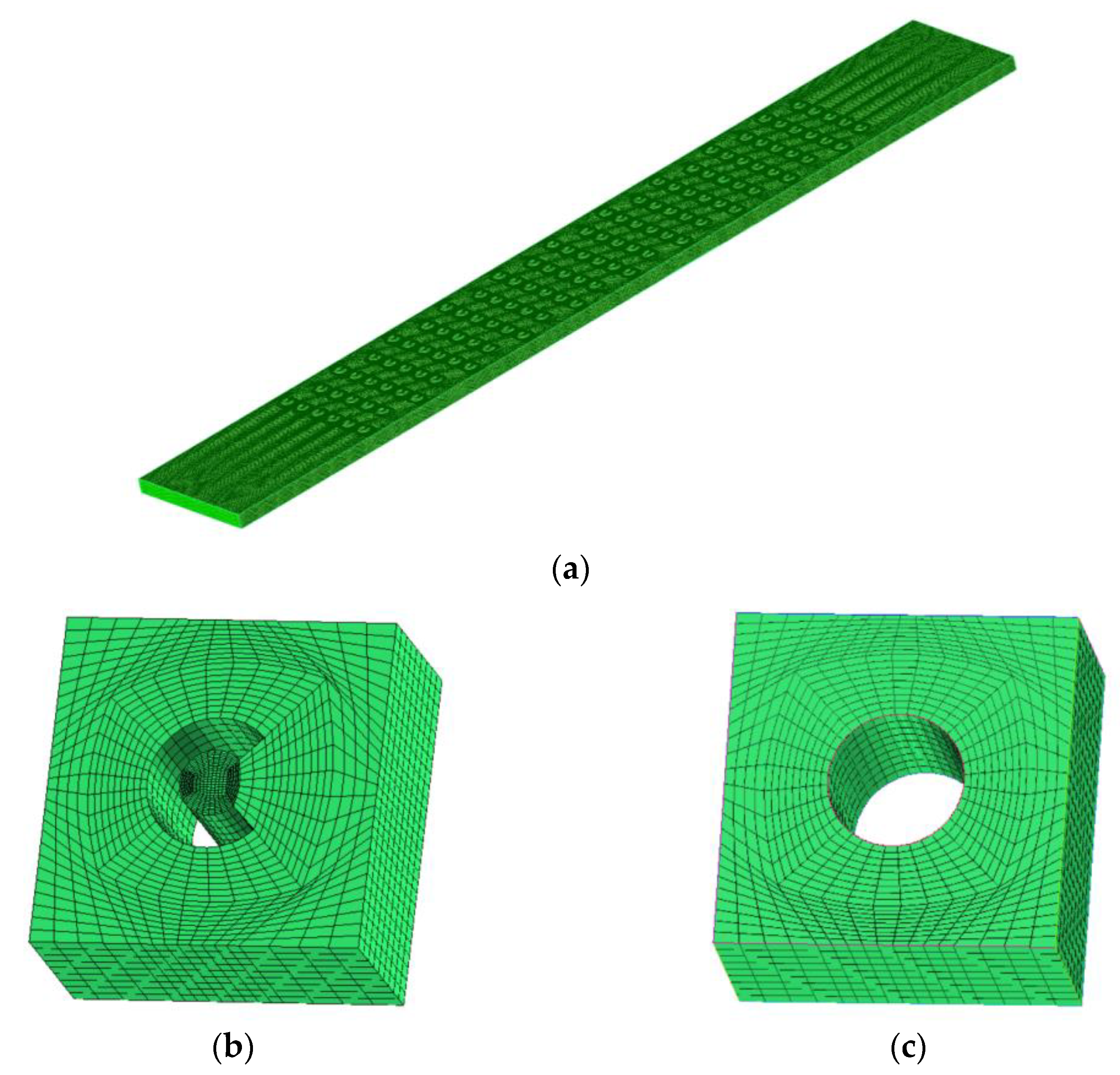
Structured hexahedral mesh was generated via ANSYS ICEM, and a mesh independence study was conducted on the four types of micro-structures. To take the meshing of the staggered ring-shaped micro-pin-fin array as an example, a total of five sets of mesh were generated, with the numbers of mesh elements of 0.96 × 10⁶, 1.30 × 10⁶, 1.61 × 10⁶, 2.02 × 10⁶ and 2.80 × 10⁶, respectively. A calculation was carried out based on different mesh densities, and the pressure drop across the channel was compared with that obtained from the finest mesh (2.80 × 10⁶). Relative errors of 2.73%, 1.70%, 1.17% and 0.39% were observed with the former four sets of mesh (0.96 × 10⁶, 1.30 × 10⁶, 1.61 × 10⁶, 2.02 × 10⁶). It could be concluded that the mesh with 2.02 × 10⁶ elements could meet the requirements of both calculation accuracy and calculation speed. A similar procedure was carried out on the other three geometric models, and the number of mesh elements employed in formal calculations is listed in Table 1. An overview of the computational domain with mesh and zoom-in views of the mesh elements adjacent to the micro-pin-fins is presented in Figure 2.

2.4. Model Validation

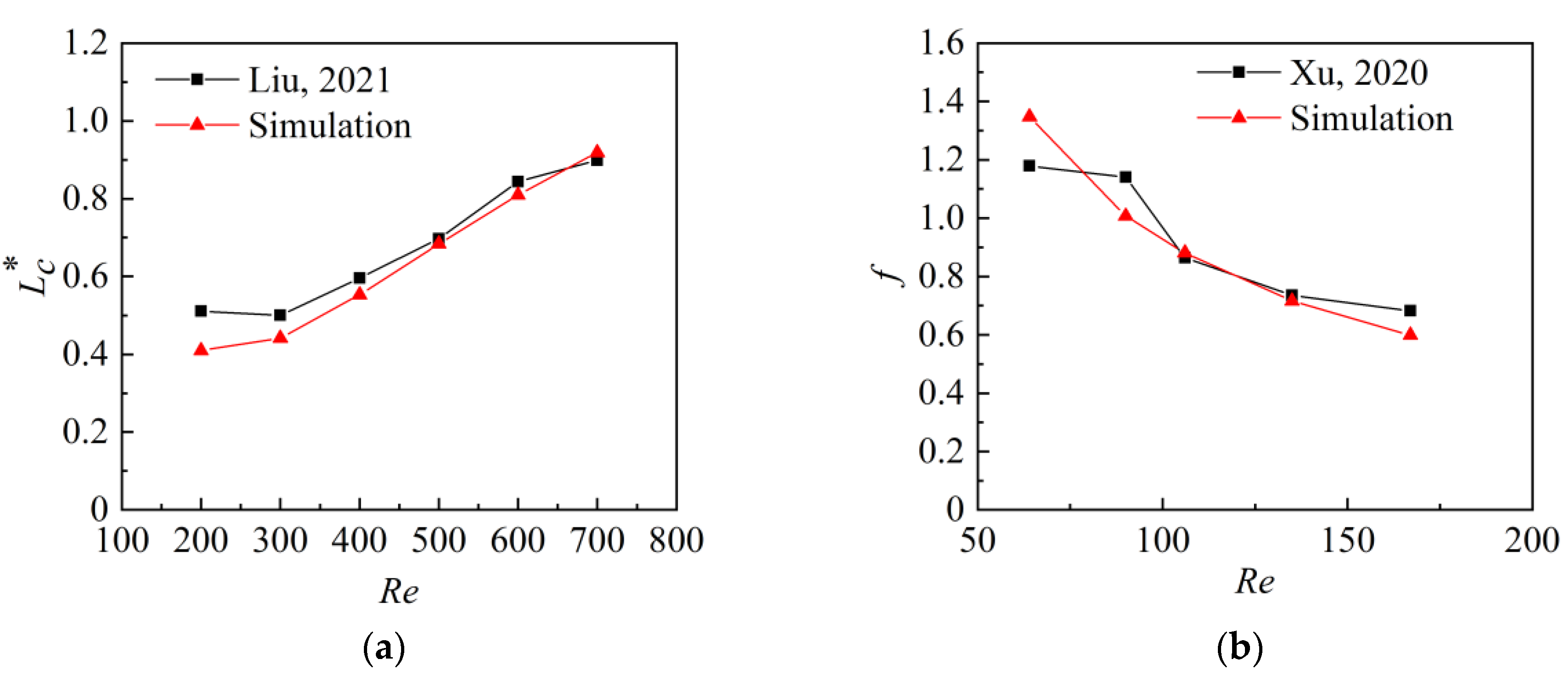
To validate the numerical model, the simulated results were compared with the experimental results in [34,35] for the channels with circular micro-pin-fin array. Good agreement could be observed from Figure 3. The maximum difference of the average dimensionless location of vortex center was 19.75%, and that of the friction factor was 14.3%, which proves the reliability of numerical simulation.

3. Results and Discussion

In this section, the flow field and vorticity distribution at the mid-plane of the channel height in the non-closed ring-shaped micro-pin-fin array is discussed. The pressure drop and heat transfer performance are explored. Results are compared with traditional circular micro-pin-fin arrays. Effects of pin-fins’ cross-section shape, layout and height are discussed.

3.1. Velocity Field and Distribution of Streamline

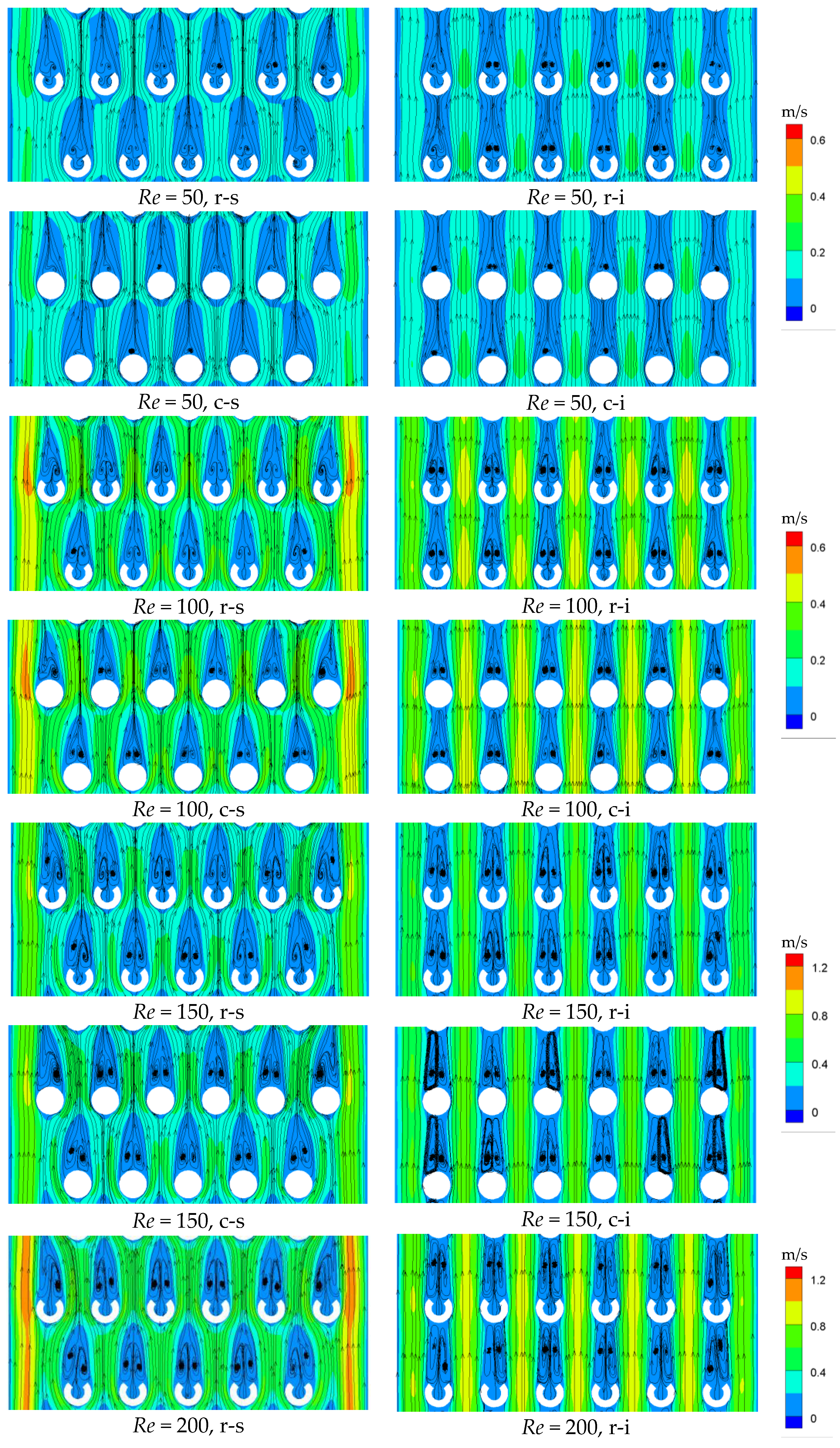
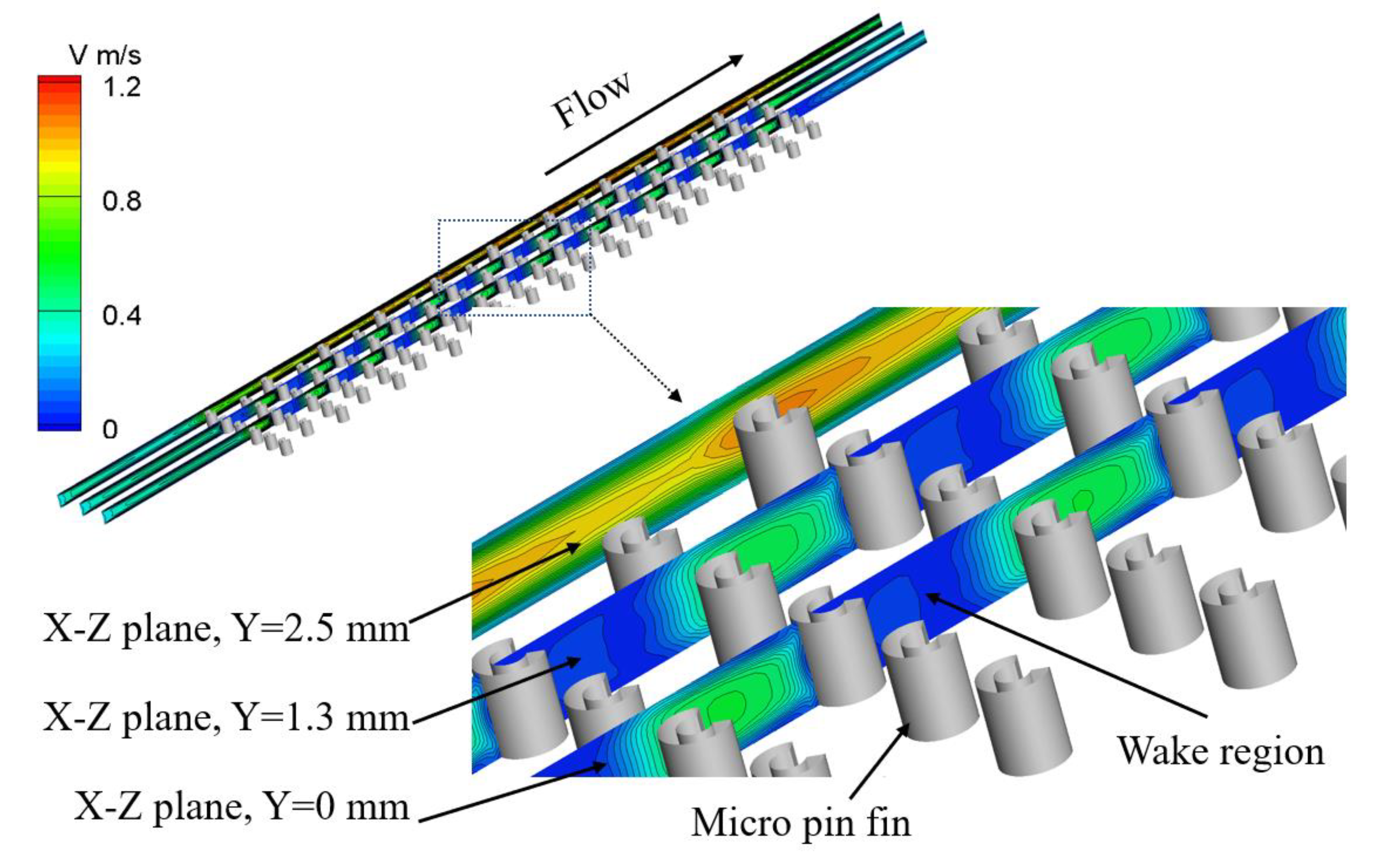
The velocity contour and streamline distribution around the 10th and 11th rows of micro-pin-fins at Reynolds numbers of 50, 100, 150 and 200 are presented in Figure 4. The velocity contour on three vertical planes in the microchannel with staggered ring-shaped micro-pin-fins at a Reynolds number of 200 is shown in Figure 5. It can be observed that when Re is low, the recirculation zone downstream of the pin-fin is inconspicuous, since the flow is dominated by viscous force. With the increase of Re, under the combined effect of reverse pressure gradient and frictional resistance, the boundary layer on the surface of the fins begins to separate, and the wake area becomes more noticeable. Single vortex and symmetrical vortex pairs appear sequentially behind the fins. In the four microstructures studied, vortex pairs appear earlier in the ring-shaped fin array than in the circular ones under the same layout. This is due to stronger disturbance caused by the opening of the non-closed ring-shaped pin-fin.
For both the ring-shaped and circular micro-pin-fin arrays, the wake area and vortex pairs in the in-line arrangement exhibit better symmetry than in the staggered arrangement. At Reynolds numbers higher than 100, boundary layer separation occurs earlier on the pin-fins adjacent to the side walls than on the internal ones in the staggered array, whereas in the in-line array, boundary layer separation occurs almost simultaneously on all the pin-fins. In addition, the wake area behind the outmost micro-pin-fins on the left and right sides is affected by the side walls, leading to an asymmetrical wake.
The increase of Reynolds number witnesses gradual expanding of the vortex and its movement downstream. As Re increases, the effect of viscous force weakens, and the location of boundary layer separation moves forward. More kinetic energy is supplemented to the boundary of the vortex, resulting in enlarged vortex size and downstream shifting of vortex center. However, as the fluid accelerates, the vortex in a pair starts to interact, gradually losing its symmetry until vortex shedding occurs.
By comparing the influence of pin-fin layouts on the velocity field, it is found that when the micro-pin-fins are staggered, only the back side of the pin-fin is in direct contact with low-speed fluid. The flow direction changes in a wavy manner, and the maximum velocity appears on two sides of the channel near the walls. In contrast, when the pin-fins are arranged in-line, the direction of the mainstream is not easily changed, and the overall velocity distribution is uniform. The main stream between two neighboring columns possesses the highest velocity, with its value lower than that of the staggered array. Both the front and back sides of the micro-pin-fins are surrounded by low-speed liquid, which becomes more obvious at higher Re. Therefore, the effective heat transfer area inside the in-line array is smaller than that of the staggered array.
The dimensionless average location of the vortex center in four types of micro-pin-fin arrays under different Reynolds numbers is shown in Figure 6. With the increase of Re, the vortices downstream the micro-pin-fins are stretched, and the vortex centers move downstream gradually, increasing the length of the wake region. Under the same Reynolds number, the distance from the rear stagnation point to the vortex center in the ring-shaped micro-pin-fin array is found to be greater than that in the circular array.
At Reynolds numbers lower than 150, for either cross-section shape of pin-fin, the dimensionless location of vortex center exhibits little difference between the staggered arrangement and the in-line arrangement, indicating that the pin-fins’ layout and spacing exert little influence on the vortex center location. At this low Reynolds number range, the size of vortex is relatively small, and the space is enough for the vortex to grow downstream each pin-fin. Effects from other pin-fins are rather negligible. However, for a given layout, the cross-section shape of the micro-pin-fin has a notable influence on the vortex center location, which is larger in the ring-shaped micro-pin-fin array than that in the circular array. This is because the existence of cavities behind the ring-shaped micro-pin-fins increases the flow area and makes the rear stagnation point move forward, lengthening the distance from the stagnation point to the vortex center. For Reynolds numbers higher than 150, a remarkable difference in vortex center location between in-line and staggered arrangements could be observed in the ring-shaped micro-pin-fin array. As can be seen in Figure 4, at Re = 200, the longitudinal span of the vortex in the in-line ring-shaped array approaches the spacing between two successive pins, which restricts its further growth in length. Kinetic energy from the main stream is therefore supplemented to the interior of the vortex, making its center move further downstream. In contrast, the vortex in the staggered ring-shaped micro-pin-fin array possesses a more sufficient space to develop, while its length is shorter than that in the in-line array due to higher transversal velocity in the main stream.

3.2. Pressure Drop Curve

The pressure along the four channels at different Reynolds numbers is depicted in Figure 7, taking the channel outlet as the reference plane. Mild pressure drop is observed along the first 6 mm of the channel since there are no micro-pin-fins in this part. At about 6 mm from the entrance, when the water flow encounters the first row of micro-pin-fins, the flow accelerates due to the reduction of flow area. The local resistance loss in the channel is approximately proportional to the flow velocity in the laminar regime. Therefore, as the velocity increases, local losses increase as well, thereby increasing the pressure drop in the channel. This phenomenon continues until the water leaves the last row of micro-pin-fins at approximately 30 mm downstream. Thereafter, there is no interference of micro-pin-fins in the channel, so the pressure changes slightly and the curve is again relatively smooth.
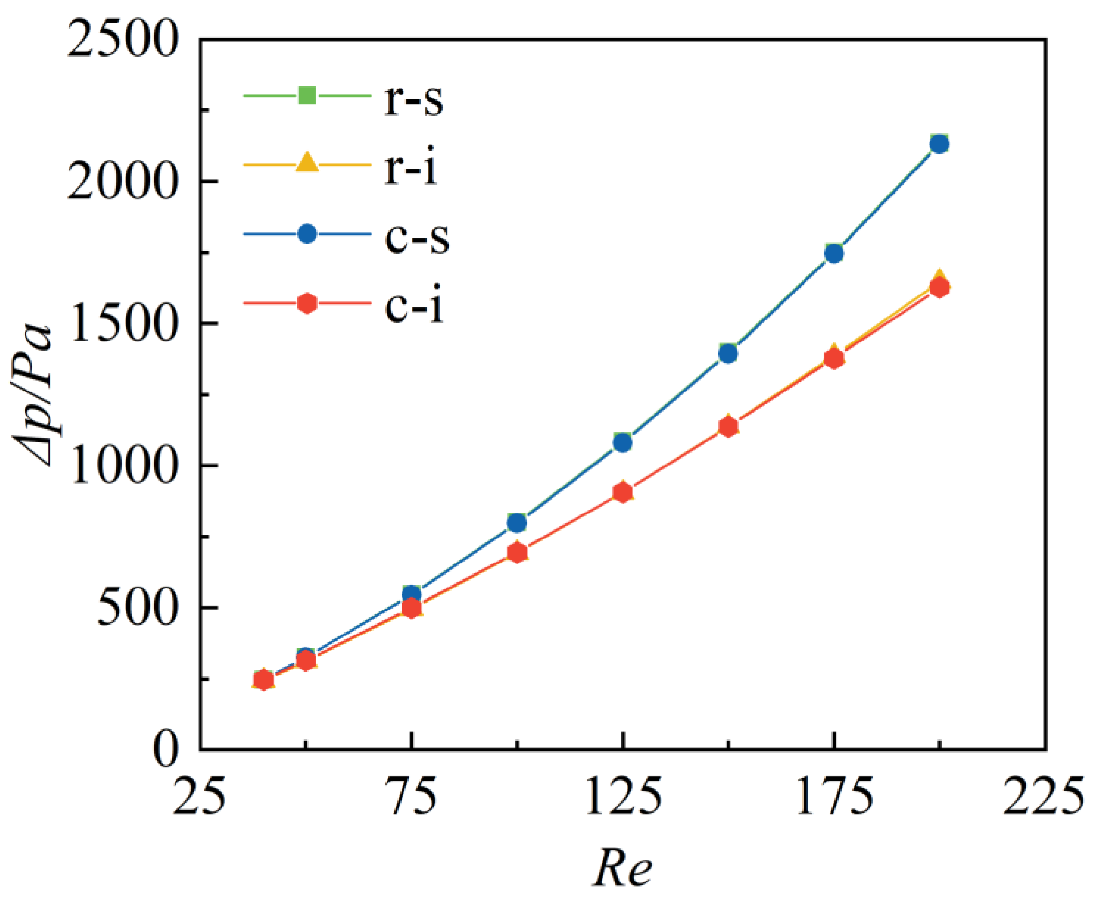
Figure 8 presents the overall pressure drop in four channels. At Re ≤ 75, there is no significant difference in pressure drop in different channels. With further increase of Re, the pressure drop rises, and the difference between in-line and staggered arrays becomes more obvious. This is because at rather low Reynolds numbers, viscous force dominates the flow, and the endwall effect is the main reason for pressure drop, while the layout and cross-sectional shape of the pin-fins play an insignificant role. As Re increases, the endwall effect gradually weakens. The development of the wake area and the growth of the vortex, which are closely related to the layout of the pin-fins, start to exert a greater influence on the overall pressure drop. More disturbance caused by the staggered arrangement produces a higher pressure drop than the in-line array. It is interesting to note that the cross-section shape of the pin-fin seems to exert little effect on pressure drop, compared with the layout. For the in-line arrangement, the maximum difference in pressure drop between ring-shaped and circular arrays is 1.43%, and it is 0.39% for the staggered array.

3.3. Vorticity Analysis

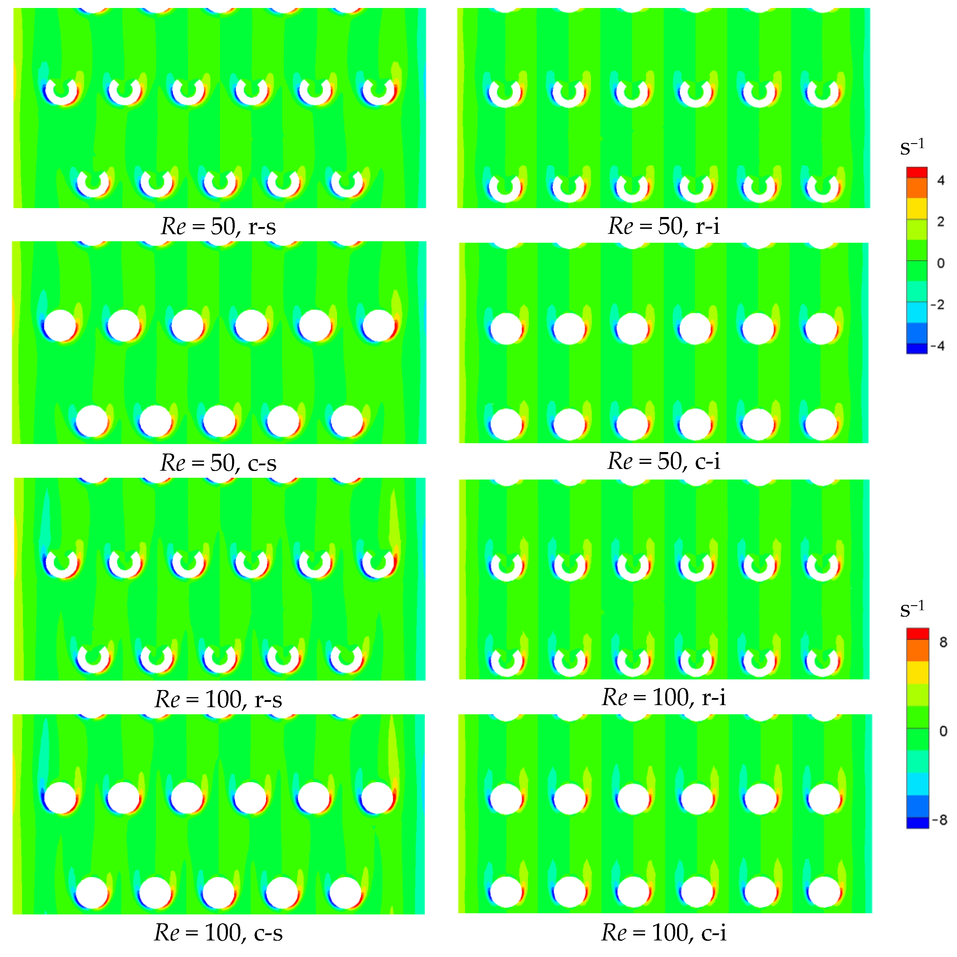
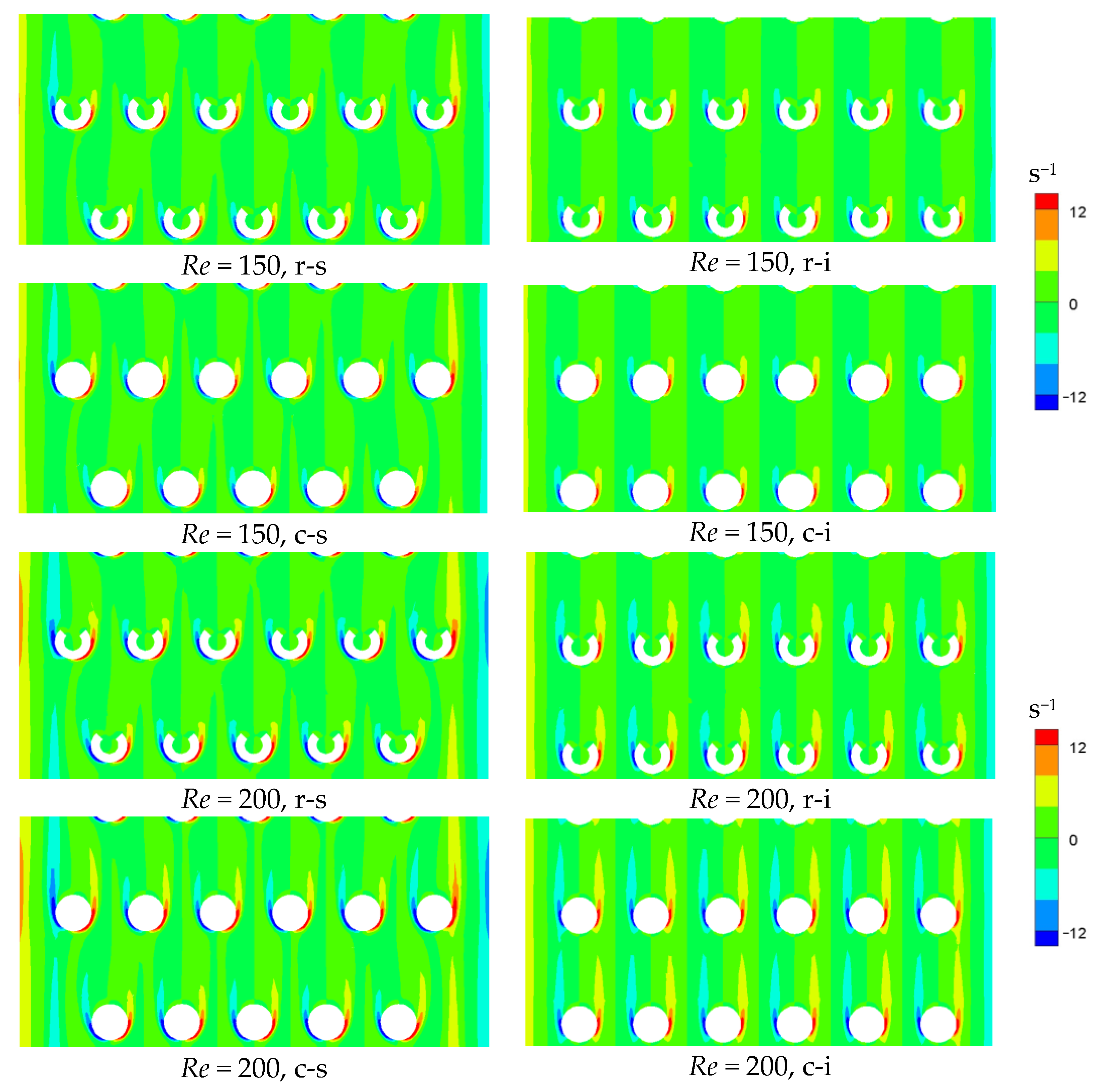
Figure 9 illustrates the vertical component of the vorticity vector around the 10th and 11th rows of micro-pin-fins at Reynolds numbers of 50, 100, 150 and 200 in four types of micro-pin-fin arrays. It is seen that symmetrical vorticity regions are formed on both sides along the micro-pin-fins, which are equal in intensity and opposite in direction (blue is negative and red is positive). Likewise, the vorticity distribution near the side walls of the channel exhibits a similar pattern. In addition, it is found that the vorticity direction along the same side of each pin-fin is consistent.
At low Reynolds numbers, the vorticity region already appears on both sides of the micro-pin-fins, and diffuses mainly along the lateral direction. With the increase of Re, the vorticity intensifies. The main direction of diffusion of vorticity gradually changes from lateral to streamwise, and the high vorticity region expands further downstream.
At a given Reynolds number, the maximum vorticity intensity in the staggered micro-pin-fin array is greater than that of the in-line array, but the downstream extension of vorticity bands is shorter. The reason is that the velocity gradient in the staggered array is larger, but the lateral velocity in the flow has hindered the streamwise diffusion of vorticity. For a given layout, the maximum vorticity intensity in the ring-shaped fin array is slightly higher than that of the circular one, while the downstream diffusion ability is slightly lower. This difference becomes more notable with the increase of Re.

3.4. Heat Transfer Characteristics

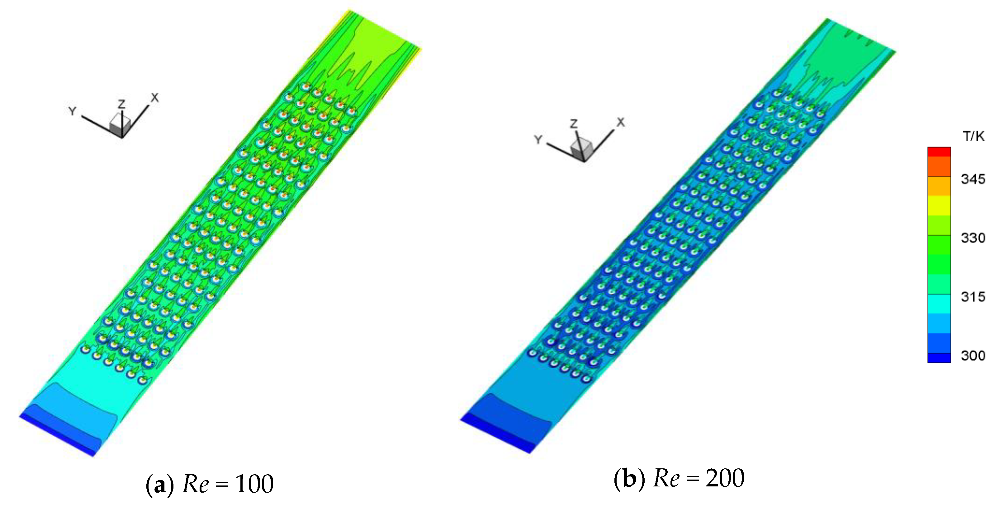
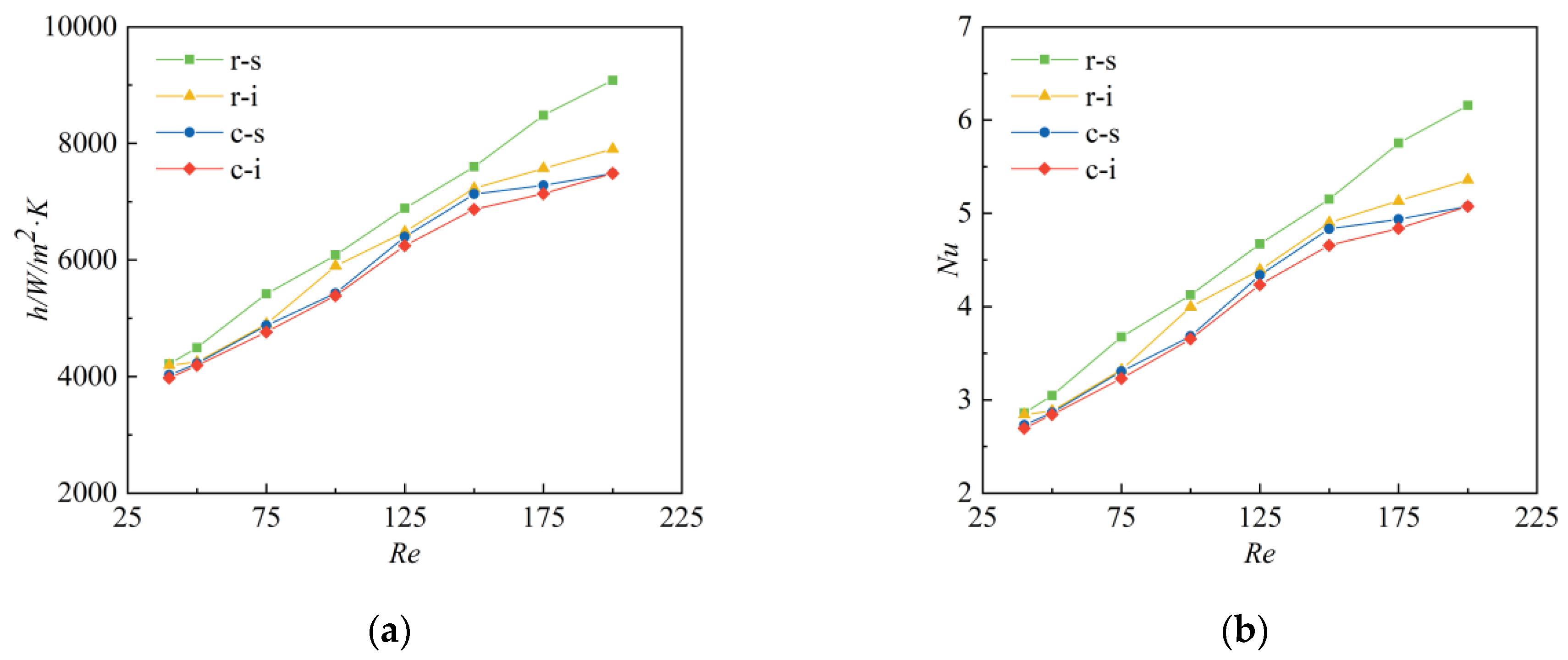
Heat transfer performance of the four configurations is evaluated at a constant heat flux of 100 kW/m2 at the bottom wall. Figure 10 depicts the temperature distribution on the bottom wall of the ring-shaped micro-pin-fin array at Reynolds numbers of 100 and 200. The existence of micro-pin-fins has interrupted the growth of the thermal boundary layer, and created local low temperature zones along the upwind side of the pin-fins. The temperature inside the cavity of each pin-fin is slightly hotter than the other regions, especially in the last few rows. Figure 11 shows the convective heat transfer coefficient and Nusselt number in four microstructures at different Reynolds numbers. Both heat transfer coefficient and Nu increase with the increase of Re. For either ring-shaped or circular micro-pin-fin, heat transfer in the staggered array outperforms that in the in-line array, which attributes to better fluid mixing in the flow and a larger effective heat transfer area, as discussed in Section 3.1. A maximum increase of 15% in heat transfer coefficient is observed in the staggered array in comparison with the in-line array. The best heat transfer performance is achieved by the staggered ring-shaped micro-pin-fin array. It can be inferred from the previous discussion that additional disturbance caused by the opening might facilitate fluid mixing in the ring-shaped array, thus enhancing heat transfer. Therefore, under the same layout, the heat transfer coefficient of the ring-shaped micro-pin-fin array is always higher than that of the circular array, with a maximum increase of 21.34%.

3.5. Thermal-Hydraulic Performance Evaluation

To comprehensively evaluate the flow and heat transfer performance of the microstructure, the thermal-hydraulic performance factor (TPF) is introduced to examine the effect of pin-fin’s cross-sectional shape and layout on the overall thermal-hydraulic performance of the system. TPF is expressed as:
TPF = N u fin / Nu 0 f fin / f 0 1 / 3
where Nu0 and f0 represent the Nusselt number and friction factor of a plain microchannel of the same size without fins.
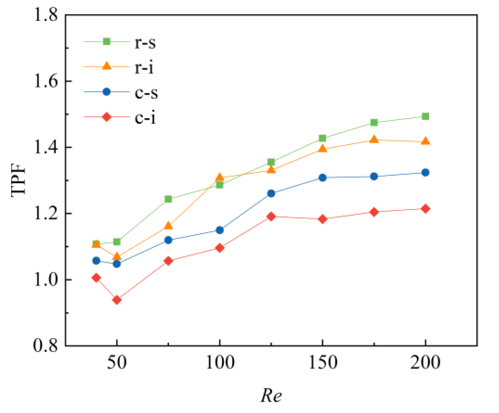
Figure 12 depicts the thermal-hydraulic performance factor in four types of micro-pin-fin array at various Reynolds numbers. In the Reynolds number range studied, TPF increases with Re in each configuration, except for the in-line arrays at low Reynolds numbers (<50). The TPF of the ring-shaped micro-pin-fin array always exceeds that of the circular micro-pin-fin array, indicating an augmentation in the overall thermal-hydraulic performance of the novel microstructure. This might also be inferred from the findings of the previous sections that the Nusselt number improves while change in pressure drop is negligibly small. The augmentation effect of the ring-shaped pin-fin becomes more obvious at higher Reynolds numbers. Of the four configurations studied, the staggered ring-shaped micro-pin-fin array exhibits the best comprehensive heat transfer performance, with a maximum increase of 12.83% in TPF compared with the staggered circular micro-pin-fin array, and a 49.4% increase compared with the plain microchannel.

3.6. Effect of the Pin-Fin Height

To further evaluate the effect of pin-fin height on the comprehensive thermal-hydraulic performance of the microstructure, TPF of the staggered ring-shaped and circular micro-pin-fin arrays with fin heights of 0.2 mm, 0.5 mm and 1.0 mm are compared. As depicted in Figure 13, TPF first increases and then decreases with the fin height in both the ring-shaped and circular fin arrays. Fins with a height of 0.5 mm exhibit the best overall performance of the three heights studied. TPF of fins with a height of 0.2 mm is less than unity in the Reynolds number range of 50–200, indicating that the heat transfer enhancement is less than the required pumping power. For micro-pin-fins with a height of 1.0 mm, the resistance loss penalty outweighs the heat transfer augmentation at low Reynolds numbers, but gradually this pattern gets reversed as the Reynolds number increases. In addition, it is noted that with very low fin height (0.2 mm), the cross-sectional shape of the pin-fin does not exert much influence on the performance of the microdevice, whereas the endwall effect originating from the top and bottom channel walls might play a more important role. As the fin height grows, differences in TPF become apparent between ring-shaped and circular pin-fin arrays, with the ring-shaped array always outperforming the circular array with fin heights of 0.5 mm and 1.0 mm. To conclude, the staggered ring-shaped micro-pin-fin with a height of 0.5 mm is the most feasible design among the studied microstructures.

4. Conclusions

A novel non-closed ring-shaped micro-pin-fin structure is proposed. The thermal-hydraulic characteristics in the novel micro-pin-fin array along with that of the circular micro-pin-fin array are investigated numerically. The key conclusions are as follows:
(1)
Vortex pairs appear at a lower Reynolds number downstream of the ring-shaped micro-pin-fin than in the traditional circular micro-pin-fin array under the same layout. With the increase of Reynolds number, the wake region expands and the vortex center shifts downstream. Better symmetry in the wake is observed in the in-line array for both cross-section shapes.
(2)
Difference in overall pressure drop in these four microchannels is subtle at low Reynolds numbers, but becomes noticeable as Re increases. The layout of the pin-fins, rather than the cross-section shape, plays a major role in influencing the pressure drop.
(3)
High vorticity regions appear on two sides of the pin-fins, with similar intensity and opposite direction. With the increase of Re, the vorticity intensifies and diffuses further downstream but narrows in width.
(4)
The staggered 3/4 ring-shaped micro-pin-fin array exhibits the best thermal performance among four types of micro-structure studied. Compared with the circular micro-pin-fin array, a maximum increase of 21.34% in heat transfer coefficient is observed in the ring-shaped micro-pin-fin array.
(5)
The best overall thermal-hydraulic performance is achieved with the staggered 3/4 ring-shaped micro-pin-fin array with a fin height of 0.5 mm, with a 49.4% increase in thermal-hydraulic performance factor compared with the plain microchannel.
(6)
On the basis of acquired findings of this investigation, future studies shall include experimental investigations on non-closed ring-shaped micro-pin-fin arrays with different heights, spacings and opening angles, exploration of flow boiling characteristics in the novel structure, integration of a multi-layer micro-pin-fin heat exchanger, etc.

Author Contributions

Investigation & writing—original draft preparation, M.C.; Writing—review and editing, C.J.; Supervision, Z.L. and N.W. All authors have read and agreed to the published version of the manuscript.

Funding

This research was funded by the National Natural Science Foundation of China (No. 52076113), the Natural Science Foundation of Shandong Province (No. ZR2021QE026), the Collaborative Innovation Project of Colleges in Jinan (No. 2021GXRC045), and the Science, Education & Industry Integration Program of Qilu University of Technology (No. 2022JBZ02-03).

Data Availability Statement

Not applicable.

Conflicts of Interest

The authors declare no conflict of interest.

Nomenclature

Roman symbols
Aminminimum cross-sectional area of flow passage in the microchannel, m2
Across-sectional area of the channel inlet, m2
c-iin-line circular micro-pin-fin array
c-sstaggered circular micro-pin-fin array
Ddiameter of the micro-pin-fin, m
ffriction factor
hheat transfer coefficient, W/(m2·K)
Lcdistance from the rear stagnation point to the center of vortex, m
Lc*dimensionless vortex center location
NuNusselt number
ppressure, Pa
qvvolumetric flow rate, m3/s
qwheat flux, kW/m2
ReReynolds number
r-iin-line ring-shaped micro-pin-fin array
r-sstaggered ring-shaped micro-pin-fin array
Ttemperature, K
TPFthermal-hydraulic performance factor
uinchannel inlet velocity, m/s
Uminaverage velocity at the minimum section of the channel, m/s
u velocity, m/s
Greek symbols
λthermal conductivity, W/(m·K)
μdynamic viscosity, N·s/m2
ρdensity, kg/m3

References

  1. Reda, S. 3D integration advances computing. Nature 2017, 547, 38–39. [Google Scholar] [CrossRef]
  2. Lu, Y.; Guo, Z.; Gong, Y.; Zhang, T.; Huang, Y.; Niu, F. Optimal study of swordfish fin microchannel heat exchanger for the next generation nuclear power conversion system of lead-based reactor. Ann. Nucl. Energy 2022, 165, 108679. [Google Scholar] [CrossRef]
  3. Yu, H.; Li, T.L.; Zeng, X.X.; He, T.B.; Mao, N. A critical review on geometric improvements for heat transfer augmentation of microchannels. Energies 2022, 15, 9474. [Google Scholar] [CrossRef]
  4. Kim, D.E.; Yu, D.I.; Jerng, D.W.; Kim, M.H.; Ahn, H.S. Review of boiling heat transfer enhancement on micro/nanostructured surfaces. Exp. Therm. Fluid Sci. 2015, 66, 173–196. [Google Scholar] [CrossRef]
  5. Xin, Z.Q.; Kong, X.Y.; Chen, J. Enhancement of heat transfer in a microchannel via passive and active control of a jet issued from the circular cylinder. Energies 2022, 15, 8287. [Google Scholar] [CrossRef]
  6. Siddiqa, S.; Molla, M.M.; Naqvi, S.B. Carreau ferrofluid flow with inclined magnetic field in an enclosure having heated cylinder. Phys. Scr. 2021, 96, 105007. [Google Scholar] [CrossRef]
  7. Roy, N.C.; Hossain, M.A.; Gorla, R.S.R.; Siddiqa, S. Natural convection around a locally heated circular cylinder placed in a rectangular enclosure. J. Non-Equilib. Thermodyn. 2021, 46, 45–59. [Google Scholar] [CrossRef]
  8. Wang, Y.Q.; Lyu, S.S.; Luo, J.L.; Luo, Z.Y.; Fu, Y.X.; Heng, Y.; Zhang, J.H.; Mo, D.C. Copper vertical micro dendrite fin arrays and their superior boiling heat transfer capability. Appl. Surf. Sci. 2017, 422, 388–393. [Google Scholar] [CrossRef]
  9. Mohammadi, A.; Koşar, A. Review on heat and fluid flow in micro pin fin heat sinks under single-phase and two-phase flow conditions. Nanoscale Microscale Thermophys. Eng. 2018, 22, 153–197. [Google Scholar] [CrossRef]
  10. Ji, C.; Liu, Z.G.; Lv, M.M. Micro-particle image velocimetry study on hydrodynamic characteristics of in-line and staggered micro pin fin arrays. Chem. Eng. Process.-Process Intensif. 2022, 179, 109058. [Google Scholar] [CrossRef]
  11. Zhang, Y.H.; Zhou, J.; Zhou, W.J.; Qi, B.J.; Wei, J.J. CHF correlation of boiling in FC-72 with micro-pin-fins for electronics cooling. Appl. Therm. Eng. 2018, 138, 494–500. [Google Scholar] [CrossRef]
  12. Jung, K.M.; Ajith, K.R.; Udaya, K.G.; Lee, H.J. Experimental study on two-phase pressure drop and flow boiling heat transfer in a micro pin fin channel heat sink under constant heat flux. Exp. Heat Transf. 2021, 34, 162–185. [Google Scholar] [CrossRef]
  13. Mohammadi, A.; Kosar, A. Hydrodynamic and thermal performance of microchannels with different staggered arrangements of cylindrical micro pin fins. J. Heat Transf. 2017, 139, 062402. [Google Scholar] [CrossRef]
  14. Mohammadi, A.; Kosar, A. Hydrodynamic and thermal performance of microchannels with different in-line arrangements of cylindrical micro pin fins. J. Heat Transf. 2016, 138, 122403. [Google Scholar] [CrossRef]
  15. Guan, N.; Liu, Z.G.; Zhang, C.W. Numerical investigation on heat transfer of liquid flow at low Reynolds number in micro-cylinder-groups. Heat Mass Transf. 2012, 48, 1141–1153. [Google Scholar] [CrossRef]
  16. Guan, N.; Luan, T.; Jiang, G.L.; Liu, Z.G.; Zhang, C.W. Influence of heating load on heat transfer characteristics in micro-pin-fin arrays. Heat Mass Transf. 2016, 52, 393–405. [Google Scholar] [CrossRef]
  17. Hithaish, D.; Saravanan, V.; Umesh, C.K.; Seetharamu, K.N. Thermal management of electronics: Numerical investigation of triangular finned heat sink. Therm. Sci. Eng. Prog. 2022, 30, 108679. [Google Scholar] [CrossRef]
  18. Hou, T.B.; Xu, D.M. Pressure drop and heat transfer performance of microchannel heat exchangers with elliptical concave cavities. Appl. Therm. Eng. 2023, 218, 119351. [Google Scholar] [CrossRef]
  19. Bhandari, P.; Prajapati, Y.K. Influences of tip clearance on flow and heat transfer characterstics of open type micro pin fin heat sink. Int. J. Therm. Sci. 2022, 179, 107714. [Google Scholar] [CrossRef]
  20. Lv, M.M.; Liu, Z.G.; Chi, W.T.; Ma, C.; Duan, L. Investigation on flow through staggered micro pin fin arrays with variable longitudinal spacings using Micro-PIV. Nanoscale Microscale Thermophys. Eng. 2022, 26, 198–217. [Google Scholar] [CrossRef]
  21. Jia, Y.T.; Huang, J.W.; Wang, J.T.; Li, H.W. Heat transfer and fluid flow characteristics of microchannel with oval-shaped micro pin fins. Entropy 2021, 23, 1482. [Google Scholar] [CrossRef] [PubMed]
  22. Wang, P.; Chen, L. Thermal and hydraulic performance of micro pin fin heat sinks with different pin fin shapes. IOP Conf. Ser. Mater. Sci. Eng. 2019, 542, 012053. [Google Scholar] [CrossRef]
  23. Xu, F.Y.; Pan, Z.H.; Wu, H.Y. Experimental investigation on the flow transition in different pin-fin arranged microchannels. Microfluid. Nanofluidics 2018, 22, 11. [Google Scholar] [CrossRef]
  24. Liu, Z.G.; Guan, N.; Zhang, C.W.; Jiang, G.L. The flow resistance and heat transfer characteristics of micro pin fins with different cross-sectional shapes. Nanoscale Microscale Thermophys. Eng. 2015, 19, 221–243. [Google Scholar] [CrossRef]
  25. Xia, G.D.; Chen, Z.; Cheng, L.X.; Ma, D.D.; Zhai, Y.L. Micro-PIV visualization and numerical simulation of flow and heat transfer in three micro pin-fin heat sinks. Int. J. Therm. Sci. 2017, 119, 9–23. [Google Scholar] [CrossRef]
  26. Dupuis, P.; Cormier, Y.; Fenech, M.; Jodoin, B. Heat transfer and flow structure characterization for pin fins produced by cold spray additive manufacturing. Int. J. Heat Mass Transf. 2016, 98, 650–661. [Google Scholar] [CrossRef]
  27. Hua, J.Y.; Li, G.; Zhao, X.B.; Li, Q.H. Experimental study on thermal performance of micro pin fin heat sinks with various shapes. Heat Mass Transf. 2017, 53, 1093–1104. [Google Scholar] [CrossRef]
  28. Omri, M.; Smaoui, H.; Frechette, L.; Kolsi, L. A new microchannel heat exchanger configuration using CNT-nanofluid and allowing uniform temperature on the active wall. Case Stud. Therm. Eng. 2022, 32, 101866. [Google Scholar] [CrossRef]
  29. Yan, Y.F.; Xue, Z.G.; Xu, F.L.; Li, L.X.; Shen, K.M.; Li, J.B.; Yang, Z.Q.; He, Z.Q. Numerical investigation on thermal-hydraulic characteristics of the micro heat sink with gradient distribution pin fin arrays and narrow slots. Appl. Therm. Eng. 2022, 202, 117836. [Google Scholar] [CrossRef]
  30. Woodcock, C.; Yu, X.; Plawsky, J.; Peles, Y. Piranha Pin Fin (PPF)—Advanced flow boiling microstructures with low surface tension dielectric fluids. Int. J. Heat Mass Transf. 2015, 90, 591–604. [Google Scholar] [CrossRef]
  31. Yu, X.; Woodcock, C.; Plawsky, J.; Peles, Y. An investigation of convective heat transfer in microchannel with Piranha Pin Fin. Int. J. Heat Mass Transf. 2016, 103, 1125–1132. [Google Scholar] [CrossRef]
  32. Chien, L.H.; Liao, W.R.; Ghalambaz, M.; Yan, W.M. Experimental study on convective boiling of micro-pin-finned channels with parallel arrangement fins for FC-72 dielectric fluid. Int. J. Heat Mass Transf. 2019, 138, 390–400. [Google Scholar] [CrossRef]
  33. Liao, W.R.; Chien, L.H.; Ghalambaz, M.; Yan, W.M. Experimental study of boiling heat transfer in a microchannel with nucleated-shape columnar micro-pin-fins. Int. Commun. Heat Mass Transf. 2019, 108, 104277. [Google Scholar] [CrossRef]
  34. Liu, Z.G.; Dong, K.M.; Lyu, M.M.; Ji, C.; Jiang, Y.K. Study on characteristics of flow field in micro pin fin array based on Micro-PIV. CIESC J. 2021, 72, 5094–5101. [Google Scholar]
  35. Xu, D. Simulation and Experimental Study on Flow and Heat Transfer Properties of Micro Pin Fins with Different Shapes; Nanjing Normal University: Nanjing, China, 2020. [Google Scholar]
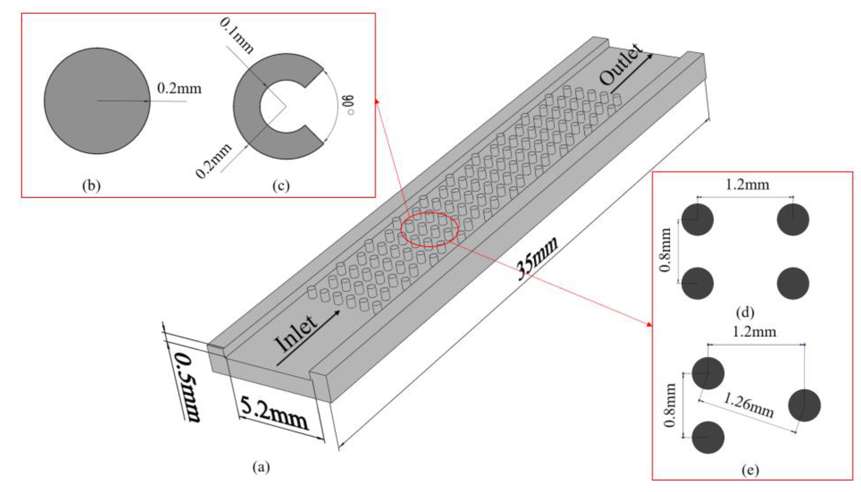
Figure 1. Sketch of the micro-pin-fin array (a) microchannel with pin-fins, (b) the circular micro-pin-fin, (c) the 3/4 ring-shaped micro-pin-fin, (d) in-line arrangement and (e) staggered arrangement.
Energies 16 03481 g001
Figure 2. Computational domain with mesh. (a) Computational domain with mesh; (b) Zoomed-in view around the ring-shaped micro-pin-fin; (c) Zoomed-in view around the circular micro-pin-fin.
Energies 16 03481 g002
Figure 3. Comparison of experimental results and simulation results (a) average dimensionless location of vortex center [34]; (b) friction factor [35].
Energies 16 03481 g003
Figure 4. Velocity contour and streamline distribution in four types of micro-pin-fin arrays at different Re.
Energies 16 03481 g004aEnergies 16 03481 g004b
Figure 5. Velocity contour on parallel vertical planes in the staggered ring-shaped micro-pin-fin channel at Re = 200.
Energies 16 03481 g005
Figure 6. Average dimensionless location of vortex center in four types of micro-pin-fin arrays at different Re.
Energies 16 03481 g006
Figure 7. Pressure along the microchannel with four types of micro-pin-fin array at Re of (a) 50, (b) 100, (c) 150 and (d) 200.
Energies 16 03481 g007
Figure 8. Variations of pressure drop vs. Reynolds number in four channels.
Energies 16 03481 g008
Figure 9. Vorticity distribution in four types of micro-pin-fin array at different Re.
Energies 16 03481 g009aEnergies 16 03481 g009b
Figure 10. Temperature distribution in the ring-shaped micro-pin-fin array.
Energies 16 03481 g010
Figure 11. Heat transfer coefficient (a) and Nusselt number (b) in four types of micro-pin-fin array at different Re.
Energies 16 03481 g011
Figure 12. Thermal-hydraulic performance factor in four types of micro-pin-fin array.
Energies 16 03481 g012
Figure 13. Variation of TPF vs. pin-fin height.
Energies 16 03481 g013
Table 1. Meshing of different micro models.
Micro-StructureNumber of Mesh Elements
r-s2.02 × 106
r-i2.00 × 106
c-s2.03 × 106
c-i1.85 × 106
Disclaimer/Publisher’s Note: The statements, opinions and data contained in all publications are solely those of the individual author(s) and contributor(s) and not of MDPI and/or the editor(s). MDPI and/or the editor(s) disclaim responsibility for any injury to people or property resulting from any ideas, methods, instructions or products referred to in the content.