Abstract
Recently, there has been a rise in the integration of renewable energy sources into power grids. As a result of this, there is a need to carry out new studies in order to understand the dynamics of power grids during disturbances that is mainly caused by the stochastic nature of wind energy. The operation of modern power grids that are tied to wind farms follows a stipulated grid requirement or grid codes, considering the allowable threshold frequency variation during grid dynamics. This paper presents a comparative study of two frequency control schemes considering grid frequency stability using two frequency control topologies. A novel dynamic flywheel scheme with a doubly fed induction generator (DFIG) variable-speed wind turbine with the coordinated control of excess kinetic energy and mechanical torque during operation was the first scheme, and a control strategy of an energy capacitor system (ECS) with a squirrel cage induction generator fixed-speed wind turbine (FSWT) was the second scheme. The salient part of this study was that the DFIG maximum point power tracking for effective smoothing of the output of the wind generator in the first scheme was designed based on the control strategy of its reference power to achieve smoothing of the wind power at the terminals of the wind generator. The model system employed in this work was a wind farm that is tied to a conventional power grid made of steam and hydro synchronous turbines. For an effective and fair comparison of results, the same natural wind speed was used in PSCAD/EMTDC for both schemes. When no control, Scheme 1, and Scheme 2 were implemented, the frequency dips were 47.20, 49.99, and 49.99 Hz with overshoots of 50.500, 50.005, and 50.001 Hz and recovery times of over 600.00, 0.01, 0.01 s, respectively, for the frequency variable.
1. Introduction
Traditional power networks mostly consist of fossil power plants that are not environmentally friendly because of emissions and pollution while in operation. Wind energy penetration into traditional grid networks, with the help of modern wind turbines, has been on the rise lately. However, one of the major drawbacks of wind energy penetration to existing grid networks is the dynamic disturbances that may occur as a result of wind speed change. Consequently, it is paramount to proffer solutions to this shortcoming so that grid operators can operate the grid networks effectively based on the stipulated grid codes or requirements.
The doubly fed induction generator (DFIG) variable-speed wind turbine system has several benefits in wind energy applications [1]. Some of the benefits of the DFIG wind generator, such as improved energy capture, the capability of decoupling active and reactive power, a requirement of only 20–30% of fractional rating power for the power converters interfacing of the rotor and grid circuits with low power loss and inexpensive converter circuitry, have made this type of wind generator very popular compared to others [2,3].
On the other hand, the fixed-speed squirrel cage induction generator (SCIG) has some merits as a wind turbine over the most popular DFIG variable-speed wind turbine system. Some of these merits are less maintenance required, low cost, rugged construction, and simple operation. Still, one of the major challenges of this wind generator technology is the large reactive power compensation requirement in its control strategy to help recover the air gap flux during scenarios of grid network disturbance. Consequently, this wind generator possesses a limited ability for grid frequency and voltage control. However, in order to overcome this wind generator shortcoming, reactive compensation devices known as flexible ac transmission systems (FACTS), such as static synchronous series compensators (SSSCs), static compensation (STATCOM) systems, or energy capacitor systems (ECSs), superconducting magnetic energy storage systems (SMESs), and battery energy storage system (BESSs), are normally used with it [4,5,6,7,8].
There are several suggested solutions regarding power network wind energy fluctuations in the literature. Some of these solutions utilize the SMES, flywheel energy storage (FES) or ECS, and BESS. Since a fast response is imperative in order to effectively compensate for and control the fluctuations of wind energy, the BESS solution may not be considered because of its slow charging/discharging processes [9,10]. In order to achieve a more efficient, fast response, an SMES, FES, or ECS can be used to effectively smooth the wind power from wind turbines [11,12,13,14,15,16]. However, the major hurdles of using FACTS devices for grid frequency control are initial and maintenance costs [17,18,19].
Among the several available solutions, FES is employed as a common solution to enhance the frequency and power quality control of grid-connected wind farms based on the stipulated grid requirements. Lower cost and more reliable short response lead time, as compared to other known frequency control solutions, may be some of the reasons why the FES is widely used. In references [20,21,22], it was reported that FESs could compensate for wind power disturbances considering wind energy penetrations into existing power networks. However, the large FES components may lead to high costs; a small FES can be used to store a fraction of energy in a small quantity that is suitable for controlling wind energy variations.
A control strategy using coordinated frequency control based on maximum power point tracking (MPPT) was reported in [23], while the implementation of a power electronics control strategy using a switching angle controller was presented in [24]. The two-area frequency control topology using DFIG with energy storage device was carried out in [25]. A cooperative control to improve the frequency dynamics of a grid system considering a DFIG wind generator incorporated with SMES was analyzed in [26]. In this study, it was found that the SMES could be used to further enhance the performance of the DFIG wind generator system during grid disturbances. In another study, the use of a FACTS device [27] and the effect of an ECS DC–DC chopper timing constant [28] on the performance of a grid-connected wind farm were investigated.
In the literature, many studies have been carried out in the area of electric power grids with large penetration levels of variable renewable energy, including wind generation and system frequency stability [29,30,31]. This has been necessary because the power grid frequency is usually jeopardized due to the high penetration of wind turbines, resulting in a lower frequency nadir and a prolonged settling of the frequency variable. Consequently, the wind farm must be disconnected to avoid damage to utilities. In order to overcome this shortcoming, the authors in [29] carried out a detailed state-of-the-art review of frequency support provision mechanisms for wind plants, while [30] suggested a DFIG-enhanced primary frequency control strategy considering pitch angle control. In their study, a de-loaded operation with a certain reserve power was investigated through the pitch angle controller of the DFIG wind turbine for power frequency regulation. The authors of the paper used a function of the pitch angle with respect to time to decrease its operation during dynamics by slowly feeding in the active power to the grid. This concept was able to improve the primary frequency response for faster recovery of the frequency variable. In a similar study carried out in [32], kinetic energy was stored and utilized in DFIG wind turbines on a wind farm to sustain the dynamics of the power grid frequency. In this study, the improvement of the frequency disturbance or nadir and smoothing of the output of the wind turbine was based on the principle of the maximum power point tracking (MPPT) operation to tackle a two-phase short-term frequency response.
In another study carried out in [33], an aggregated multi-machine model similar to that used in this current study was investigated in power system dynamic studies. The authors showed the effects of the dynamics of the various machines in power grids. Furthermore, in [34], an inertia cooperative control synthetic in nature was employed in regulating the frequency capability of wind farms instead of the traditional scheme based on the literature. In reference [35], the authors introduced a new scheme for embedded energy storage similar to the flywheel scheme employed in this study for the DFIG wind turbine system in order to boost its dynamic capabilities during power grid disturbance.
In light of the above, this paper presents a comparative study of improved grid frequency dynamic performance using a new dynamic flywheel scheme that is based on the derivation of excess kinetic energy during operation for DFIG wind generator control strategy (Scheme 1) and an ECS induction generator fixed-speed control strategy (Scheme 2). The model system in this paper comprises steam and hydro synchronous generators that are connected to two wind farms. Two scenarios were considered in evaluating the dynamic performance of the grid-connected wind farm and the entire power network. The first scenario uses Scheme 1 to improve the grid frequency dynamics of the power network by employing the coordinated MPPT controller of the DFIG wind generator system for smoothing the fluctuated wind power during periods of dynamics. The details of the controller design and control strategy of the DFIG are presented. During periods of wind speed change with values higher than the nominal rated wind turbine speed of the wind generators, there are possibilities of generating excess kinetic energy to enhance the grid frequency of the power network. However, when there are steady and low wind speeds, the generation of excess kinetic energy is not feasible. In this study, the wind farm in Scheme 2 is based on the traditional ECS that is tied to the wind farm terminal to help obtain smoothing of the fluctuated variables of the wind turbine. This is vital in order to keep the power supply steady during power grid disturbances. The evaluation of the system performance was achieved in the Power System Computer Aided Design and Electromagnetic Transient Including DC (PSCAD/EMTDC) environment [36], considering natural wind speed in Hokkaido Island, Japan, for the DFIG and fixed-speed induction generators, respectively, for both schemes. The simulation was carried out for three scenarios (Scheme 1 and Scheme 2) and an additional scenario where no grid frequency control was implemented. The wind farms were connected to the grid network at different times under the same conditions using the same wind speed for a fair comparative study. Based on the evaluation of the system, the control strategies in both schemes considered in this study enhanced the wind farms’ variables and performance, along with the existing traditional synchronous generators and the entire power grid. The comparative analysis in this paper reflects that the variables of the grid frequency and the entire power network were better enhanced during the grid dynamic periods using the proposed DFIG-coordinated Scheme 1 and the traditional ECS FACTS device in Scheme 2, considering the grid codes. Although there were considerable improvements in the frequency response in Scheme 2 due to the fast compensation of the ECS unit during dynamics, Scheme 2 did not have the capability of generating power to the grid while contributing to the stability of the power grid as with Scheme 1. This is the salient part and target of this study, as the proposed Scheme 1 is a more cost-effective means to achieve power grid stability during dynamics.
2. Model System of Study
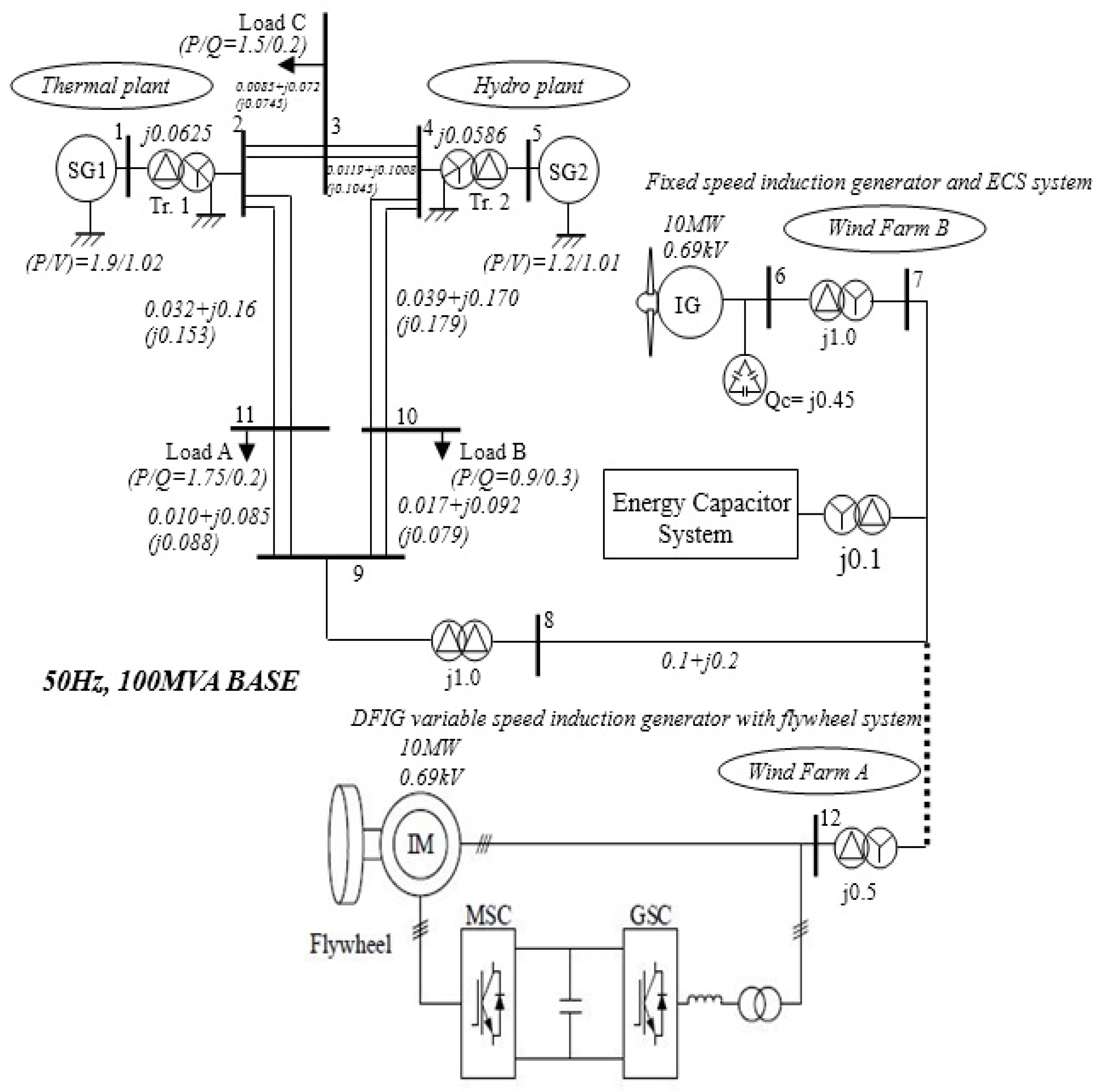
Figure 1 shows the model system of study used in this paper, with the wind turbines modeled based on [37]. The steam (SG1) and hydro turbines (SG2) were rated at 25 and 20 MW, respectively, and connected to wind farms A and B. The wind turbines in the wind farms for both schemes were each rated at 10 MW. The parameters of all the turbines in the model system are given in Table 1 [37,38]. From Figure 1, both wind farms were connected to an existing grid network made up of steam and hydro turbines. The topology and control system of the flywheel DFIG-based system is shown in wind farm A. In this wind farm, three DFIG wind turbines of smaller capacities with the same wind speed were present; however, for simulation purposes, an aggregated wind turbine of a larger capacity of 10 MW was considered in this study. The DFIG flywheel-based system in wind farm A had a machine side converter (MSC) and grid side converter (GSC) that were tied to the induction machine (IM). Wind farm B was made of an SCIG fixed-speed wind generator system with an ECS connected to its terminal to achieve smoothing of the wind power during periods of dynamics or wind speed changes. An aggregated fixed-speed induction wind turbine was also considered in this wind farm for simulation purposes.
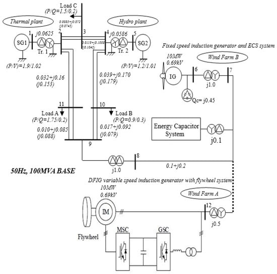
Figure 1.
Model system.

Table 1.
Generator Parameters [39].
The comparative study was carried out by connecting each wind farm to the grid network, one at a time, using the same natural wind speed for an effective comparison of the performance of the system. The parameters of the lines, transformers, and loads are shown in the model system. The power grid was assumed to be nominal with not too high or too low values of X/R. The ECS parameters are given in Table 2. Loads A, B, and C were connected between the bus bars connecting the wind farm and the other conventional synchronous generators, as shown in the model system. The grid-connected power network was operating at 100 MVA, 66 kV, and 50 Hz.

Table 2.
Energy Capacitor System Parameters [39].
3. DFIG Flywheel Control Strategy
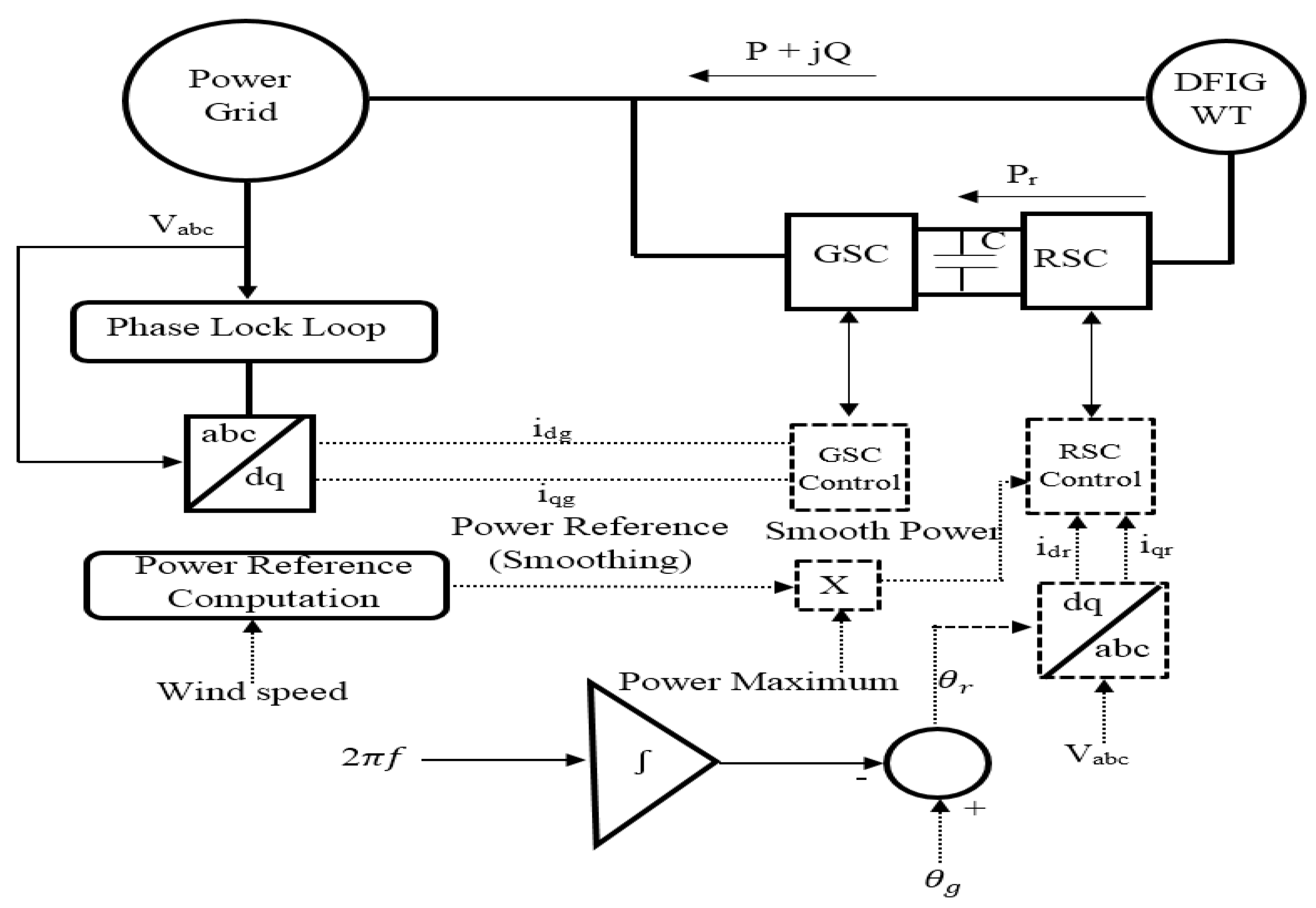
Figure 2 shows the control scheme for wind farm A. Based on the detections of the grid voltage, the phase lock loop (PLL) angle is computed for abc to dq conversion and vice versa. The calculator for the reference power ensures the smoothing of the fluctuated wind power based on the available natural wind speed. The flywheel DFIG-based scheme is typically made of a high-inertia induction generator having power converters that are connected back-to-back. These power converters are known as the rotor or machine side converter (RSC or MSC) and stator or grid side converter (SSC) or (GSC). The direct and quadrature currents, idg and iqg, are used to regulate the DFIG with the turbine for the GSC power converter for control of reactive power injection and voltage. The currents idr and iqr are used to regulate the RSC power converter for the control of the active power of the wind generator. The Scheme 1 operating principle is such that the wind generator rotating mass would be able to store and retrieve energy during dynamic operation. The flywheel scheme based on a wind generator has excess stored kinetic energy expressed as [40]
where is the flywheel rotational speed and is its moment of inertia. The available flywheel stored energy is
where and are the maximum and minimum speeds of the flywheel system, respectively. Regarding the electrical aspect of the system, the stator circuit power exchange and the electrical torque of the wind generator are given as [41,42]
where is the electrical angular velocity ( is the stator flux linkage, is the magnetizing inductance, is the stator inductance, and is the conjugate of the rotor current. From the principle of Clarke and Park transformation, the abc to dq conversion can be carried out using the rotor reference frame. Thus, Equations (3) and (4) above can be expressed based on dq frame as [43,44]
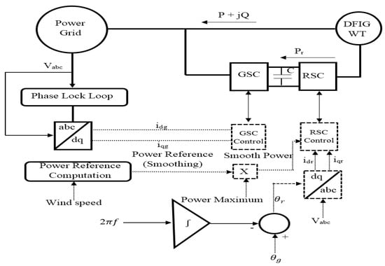
Figure 2.
DFIG variable-speed control.
Equations (3) and (4) can be expanded considering Equation (5) as
The stator active and reactive powers are equivalent to the real and imaginary components of Equation (6), expressed as
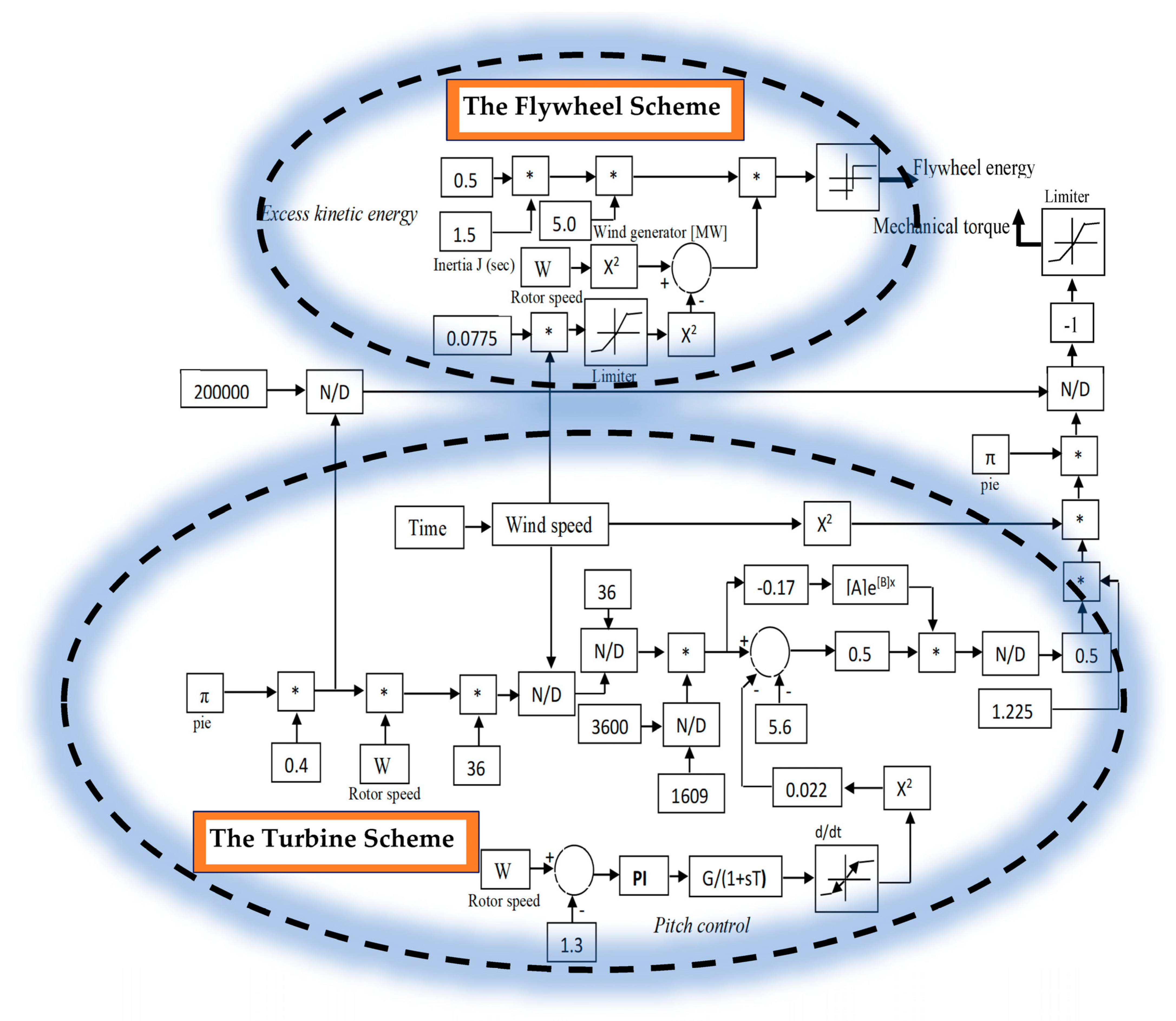
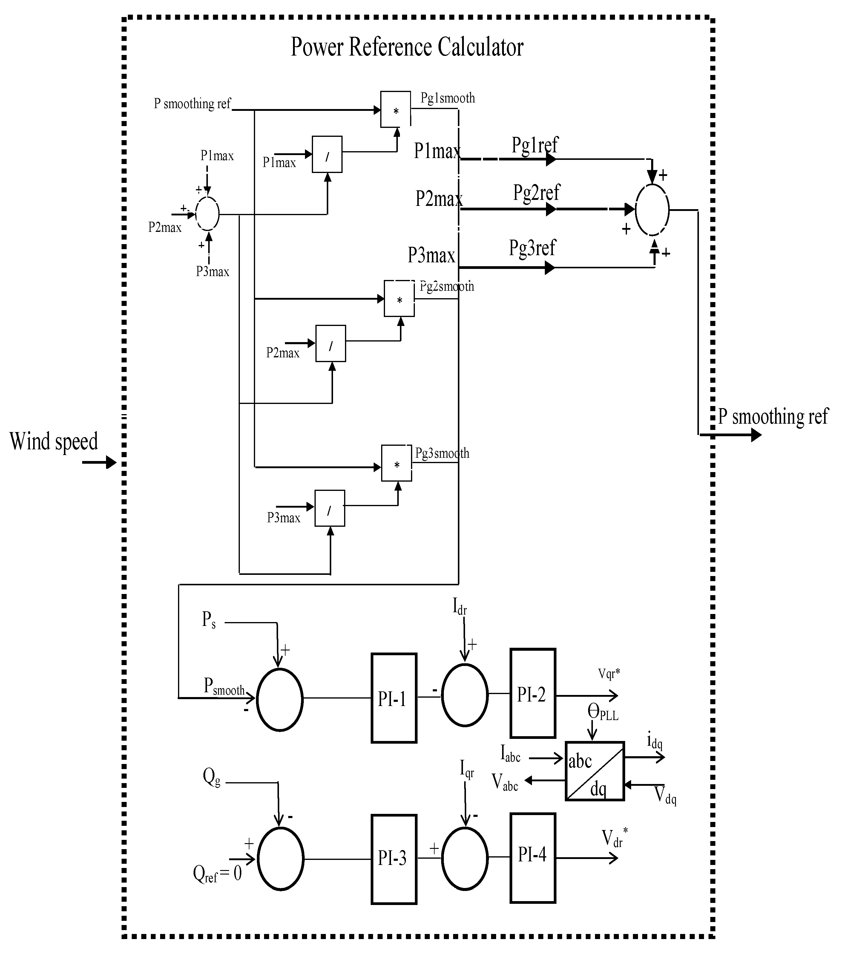
The controls of the electrical torque of the DFIG and its stator power are obtainable using the rotor current as depicted in Equations (7)–(9). In Figure 3, the computations of both the mechanical torque and the excess kinetic energy depend on the available natural wind speed. When the wind speeds are high above the nominal or rated wind turbine speed, excess kinetic energy is generated and stored in the flywheel system, which is then utilized as energy storage to enhance the grid frequency performance. In Figure 3, the design parameters and their numerical values in the control block help in the effective coordinated control of the pitch angle controller and the developed torque. Consequently, owing to motion, there is a generation of kinetic energy. Considering the wind turbine characteristics, the rated value of wind turbine rotor speed is 1.3 pu, and this is controlled by the pitch controller. The drive train scheme of the wind generator helps in transmitting the mechanical torque that is developed. The wind generator power capacity, available wind speed, and actual rotor speed and inertia are some of the variables that play important roles in the generation of kinetic energy in excess for energy storage. In Figure 4, the wind generator flywheel-based reference power calculator for Scheme 1 in wind farm A is shown. The three aggregated wind generator reference powers are Pg1ref, Pg2ref, and Pg3ref. These are generated from the wind speed via the P1max, P2 max, and P3 max, respectively, of each wind turbine and the effective Psmoothing power from the controller of the DFIG wind turbine. The functions of the reference signals are to act as set points and help in the control of the measured variables of the wind generator during dynamic operations.
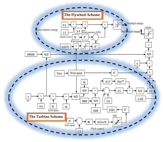
Figure 3.
MPPT flywheel control (* means reference signal).
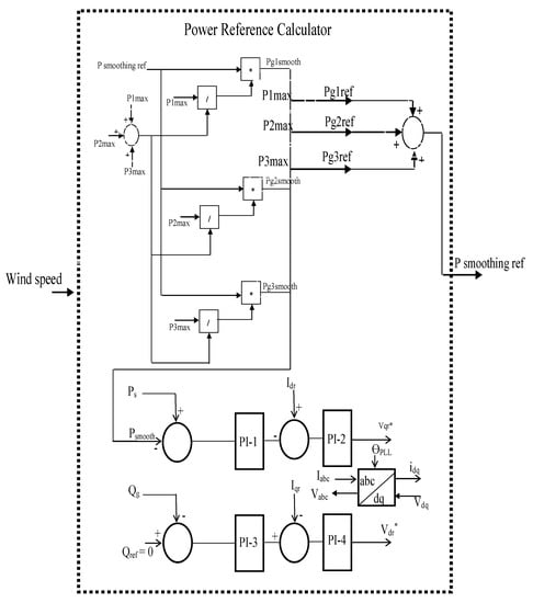
Figure 4.
DFIG flywheel reference power calculator (* means reference signal).
The reference power derivation is achieved via the same wind speed for the three wind generators with lower capacities. The resultant smooth reference power is used for the aggregated wind generator for simulation purposes in this study.
4. Energy Capacitor System for a Fixed-Speed Wind Turbine System
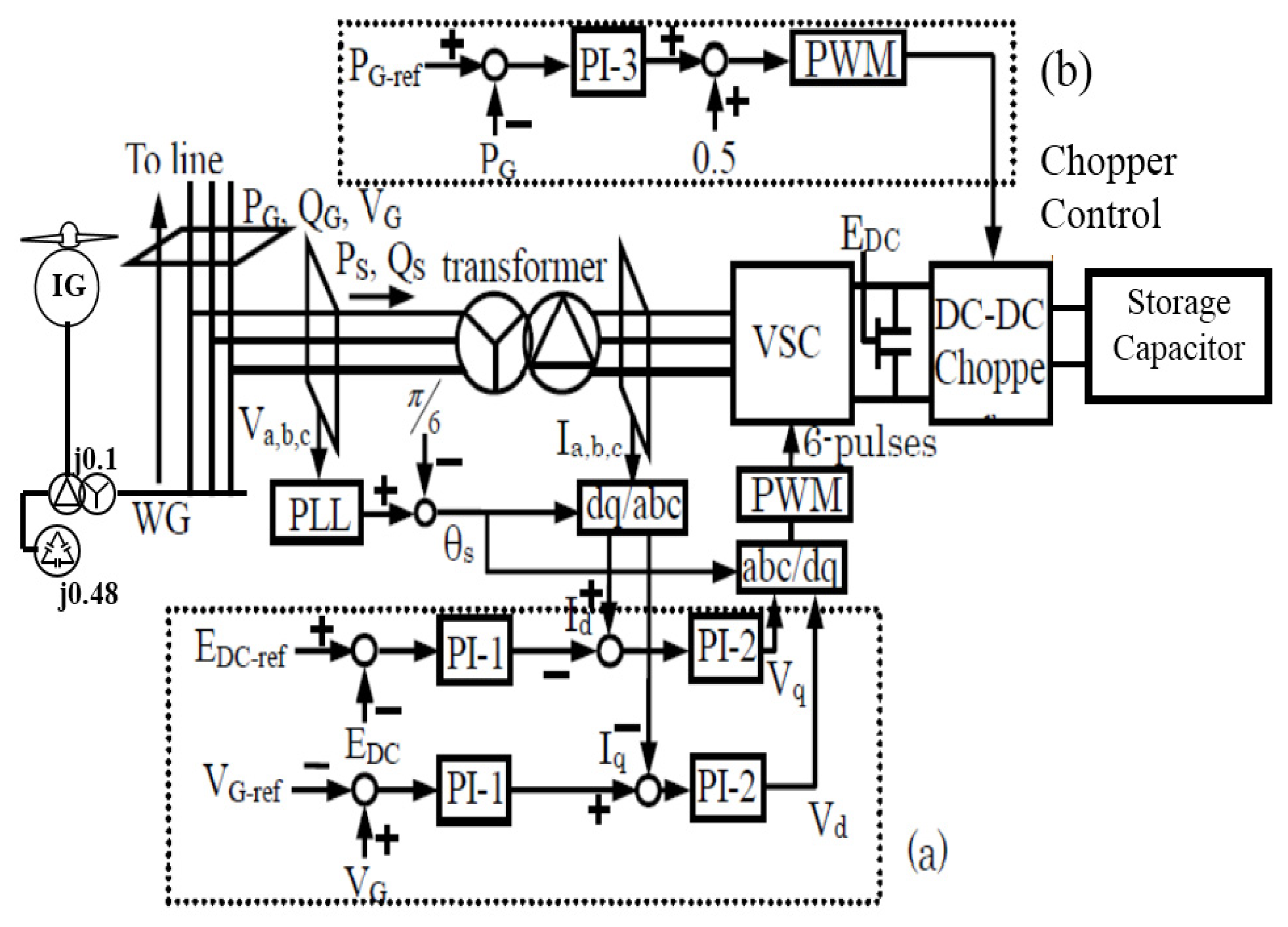
Figure 5 shows the control scheme for the ECS connected to the terminal of the fixed-speed SCIG. The PLL angle theta is used for the dq to abc transformation. The measured voltage and its reference are compared, then the proportional integral (PI) controller system is used to obtain their controlled signal. The generated resultant signal is matched with a signal generator to develop the IGBT pulse references. These reference-controlled variables are used to operate the ECS unit in order to control the wind farm in particular and the entire power network in general during dynamics. There exists a low pass filter (LPF) that is incorporated in the ECS scheme, as shown for DC–DC chopper circuitry. The reference signals for the LPF are the active powers of the grid and the wind generator. A PI controller helps control an output signal in conjuncture with a constant gain to generate a resultant signal, comparable with a triangular carrier signal generator. The DC–DC chopper for charging and discharging constraints is thus operated based on the resultant output signal.
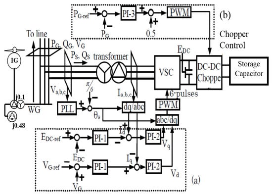
Figure 5.
Wind farm B frequency control strategy (a) ECS control scheme (b) Chopper control.
5. Simulation Results and Discussions
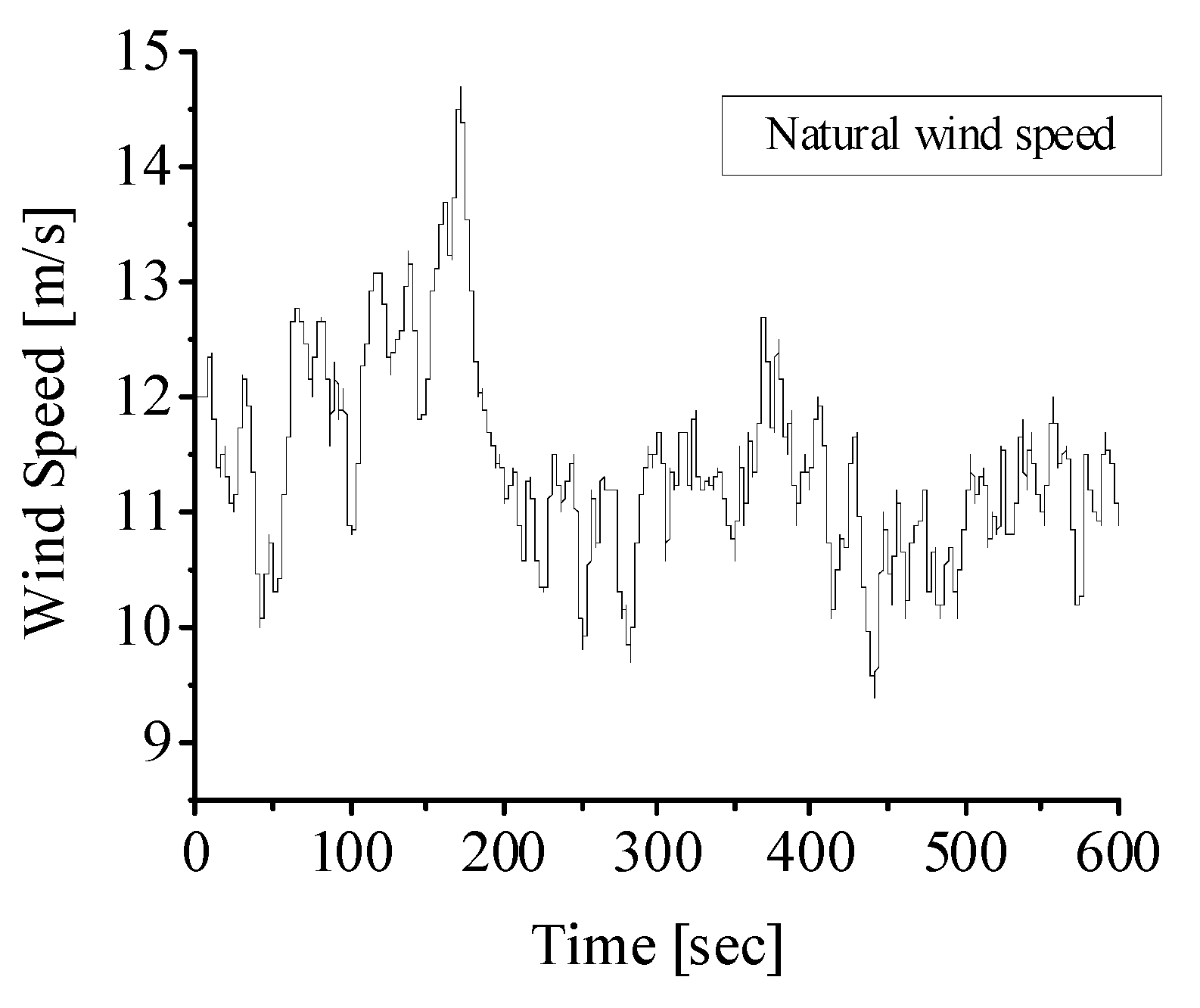
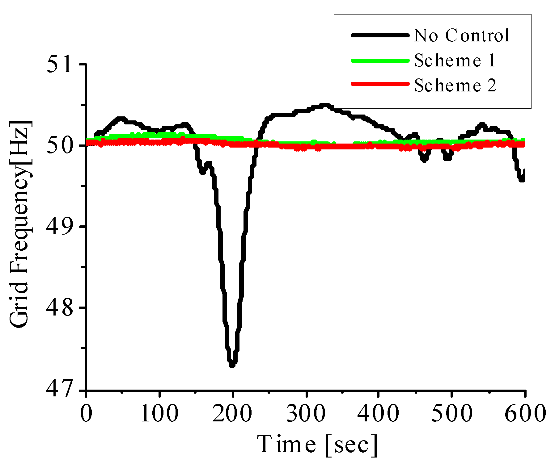
Simulations were run based on the model system in Figure 1 using the natural wind speed data shown in Figure 6, obtained from the Island of Hokkaido in Japan. The simulations were run for 600 s on the PSCAD/EMTDC platform to demonstrate the robustness of the controllers used in the study. The simulation of the grid-connected wind farm was achieved first considering no control strategy in the wind farm; in this case, the wind generator did not have an ECS unit connected nor a flywheel system embedded. Thereafter, wind farm A was connected to the grid network, and the flywheel DFIG-coordinated system (Scheme 1) was used to control the grid frequency dynamics of the power network. In the second scenario, the ECS and fixed-speed wind turbine (Scheme 2) was used to control the grid frequency dynamics of the system. The same wind speed data were used for both schemes for an effective comparative study. The wind farms were connected one at a time to the existing grid network made up of steam and hydro synchronous turbines. The responses for the grid frequency for all scenarios are shown in Figure 7.
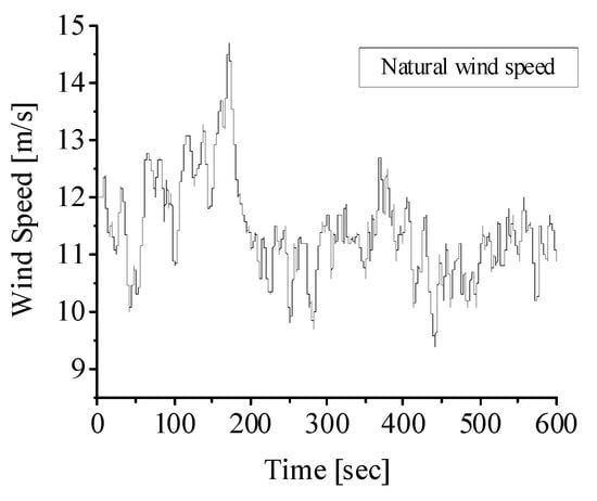
Figure 6.
Natural wind speed.
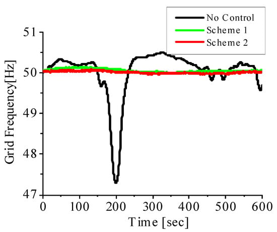
Figure 7.
Grid frequency.
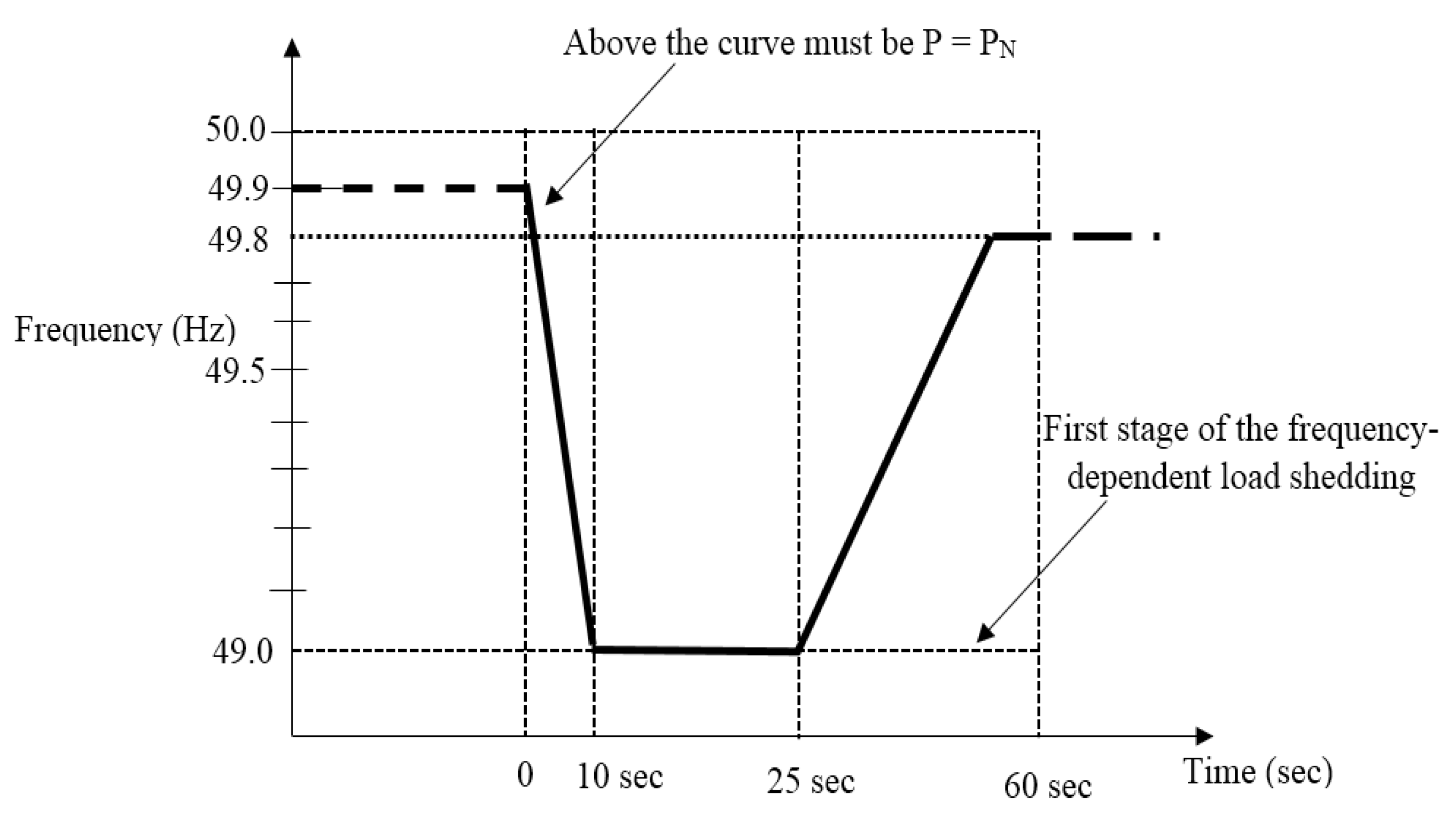
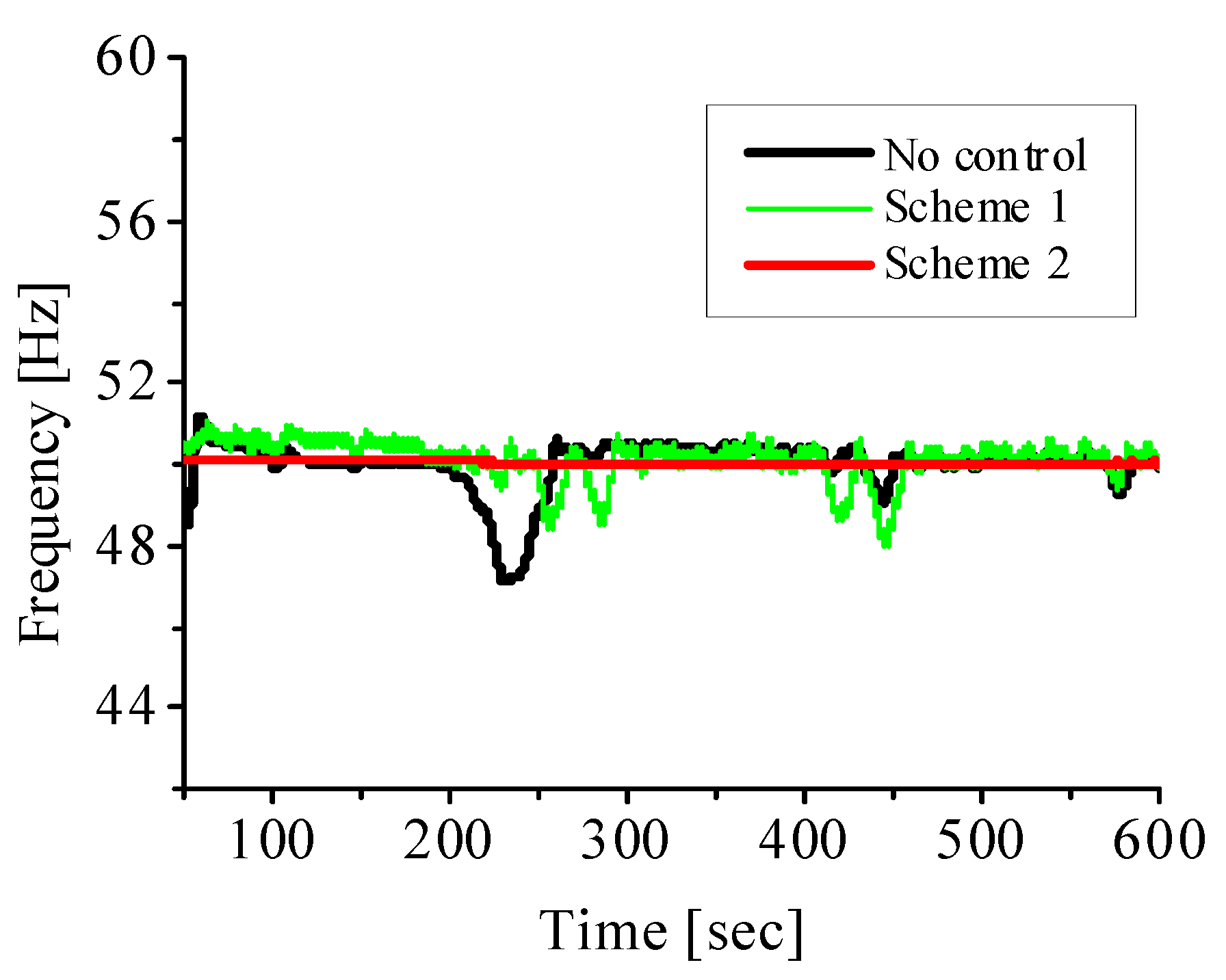
From Figure 7, when Scheme 2 was implemented based on the grid frequency control in wind farm B, better responses were achieved for the grid frequency dynamics during periods of wind speed change, with less distortion in the grid frequency of the power network during these periods compared to that of Scheme 1. A scenario in which no grid frequency control was employed in Figure 7 shows that the grid frequency could drop below 48 Hz, which is not healthy for the power network. In such a situation, the wind farm must be shut down or disconnected from the power network, based on the stipulated minimum requirement of grid frequency levels set by the grid codes for several countries, as shown in Figure 8. A typical grid requirement for grid frequency control during dynamics below 49 Hz requires the wind farm to be disconnected from the grid network.
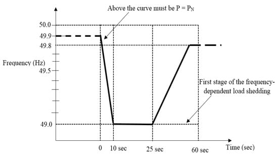
Figure 8.
Stipulated grid frequency requirement as set by E.ON NETZ GmbH.
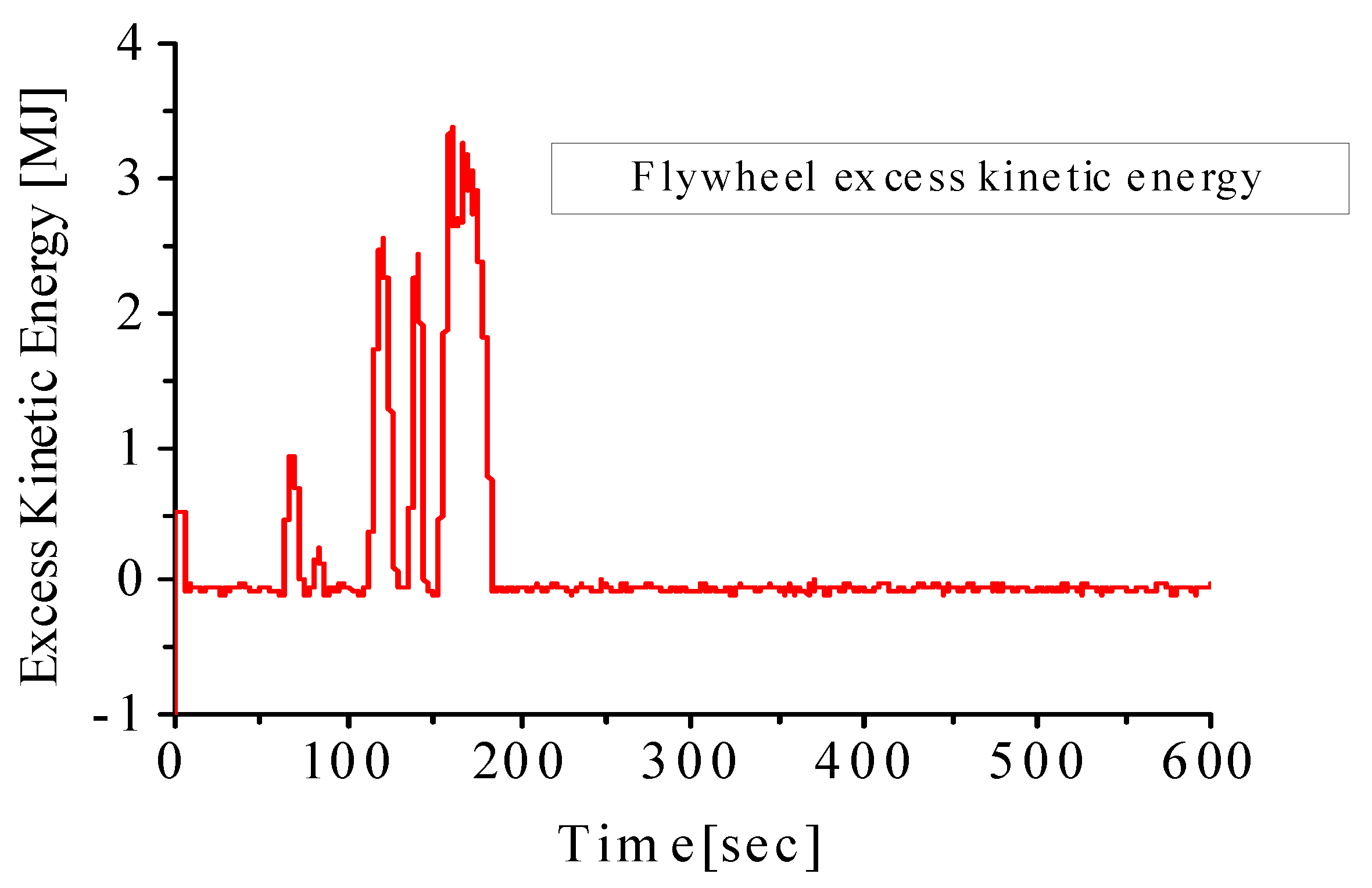
Scheme 1 was able to improve the performance of the power grid during grid dynamics by using the proposed coordinated control of the DFIG MPPT system in wind farm A, as shown in Figure 7, with good frequency performance that follows the same performance of the scenario in which the traditional use of ECS FACTS device in Scheme 2 was employed. There was considerable improvement in the frequency response in Scheme 2 due to the fast compensation during dynamics. However, Scheme 2 did not have the capability of generating power to the grid while contributing to the stability of the grid as in Scheme 1, thus making this one of the targets of this paper. Still, both schemes were able to suit the stipulated grid codes, which requires a minimum frequency dip of 49 Hz. A further investigation of the effects of proper tunning of the proportional integral (PI) controller is demonstrated in Figure 9 for a comparative study of the proposed scheme and the traditional scheme. When the DFIG wind turbine PI controllers were not properly tuned, constant oscillations of the frequency variable existed during dynamics, making the scheme unable to fulfill the required grid codes. However, proper tuning would give the result obtained in Figure 7, fulfilling the stipulated grid codes for effective frequency control. The excess kinetic energy developed by the wind turbine flywheel system based on the control strategy in Figure 3 is shown in Figure 10. From Figure 10, more kinetic energy was generated for energy storage in the flywheel system in Scheme 2 during periods of 100 to 200 s of high wind speed changes above the rated wind speed (12 m/s) of the fixed-speed wind generator based on the nature of the natural wind speed data shown in Figure 6. Thus, no kinetic energy was developed during low wind periods, showing the effectiveness of the controllers employed during the grid’s dynamic periods.
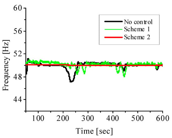
Figure 9.
Comparative study of grid frequency response without proper PI controller tuning.
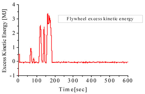
Figure 10.
Excess kinetic energy.
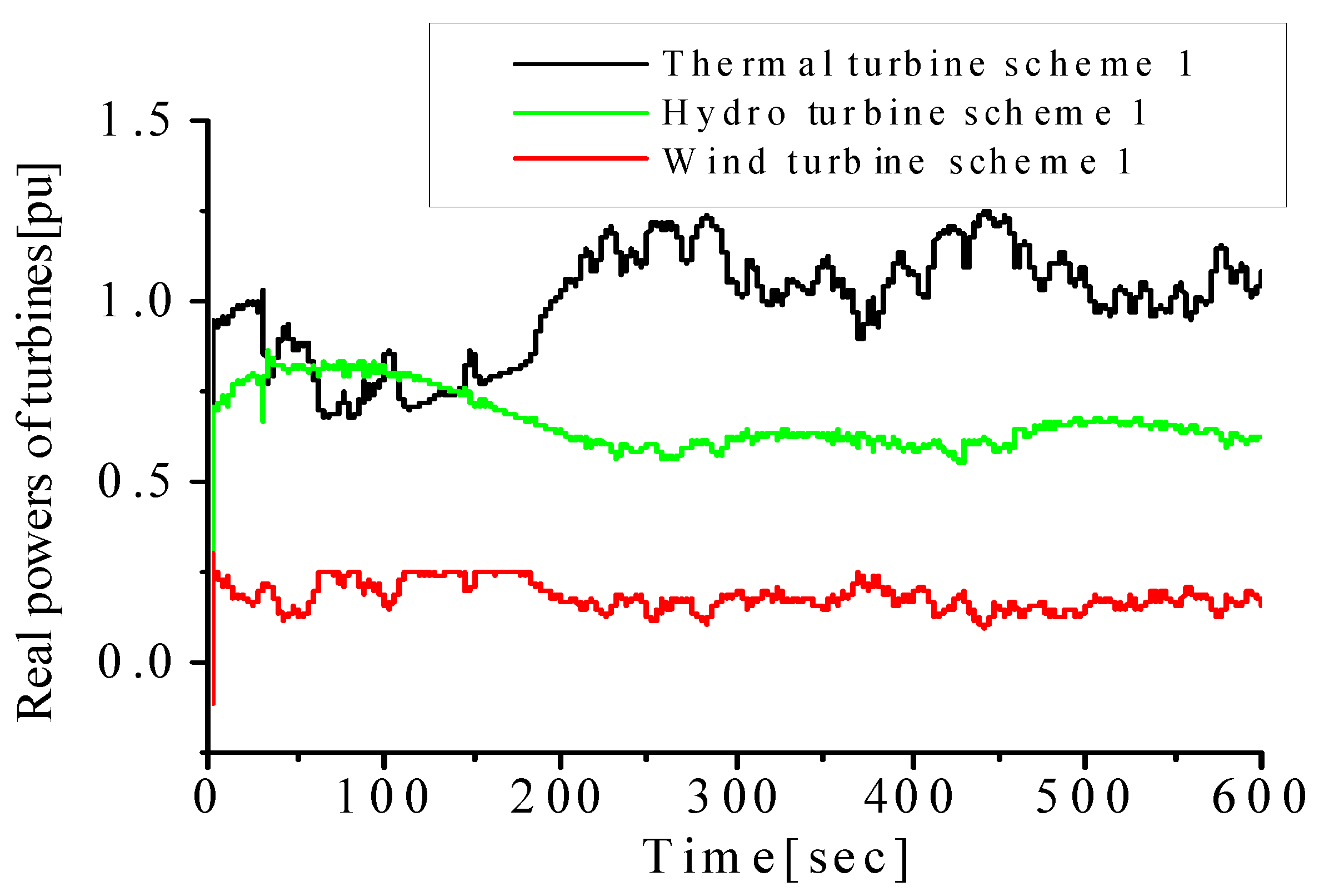
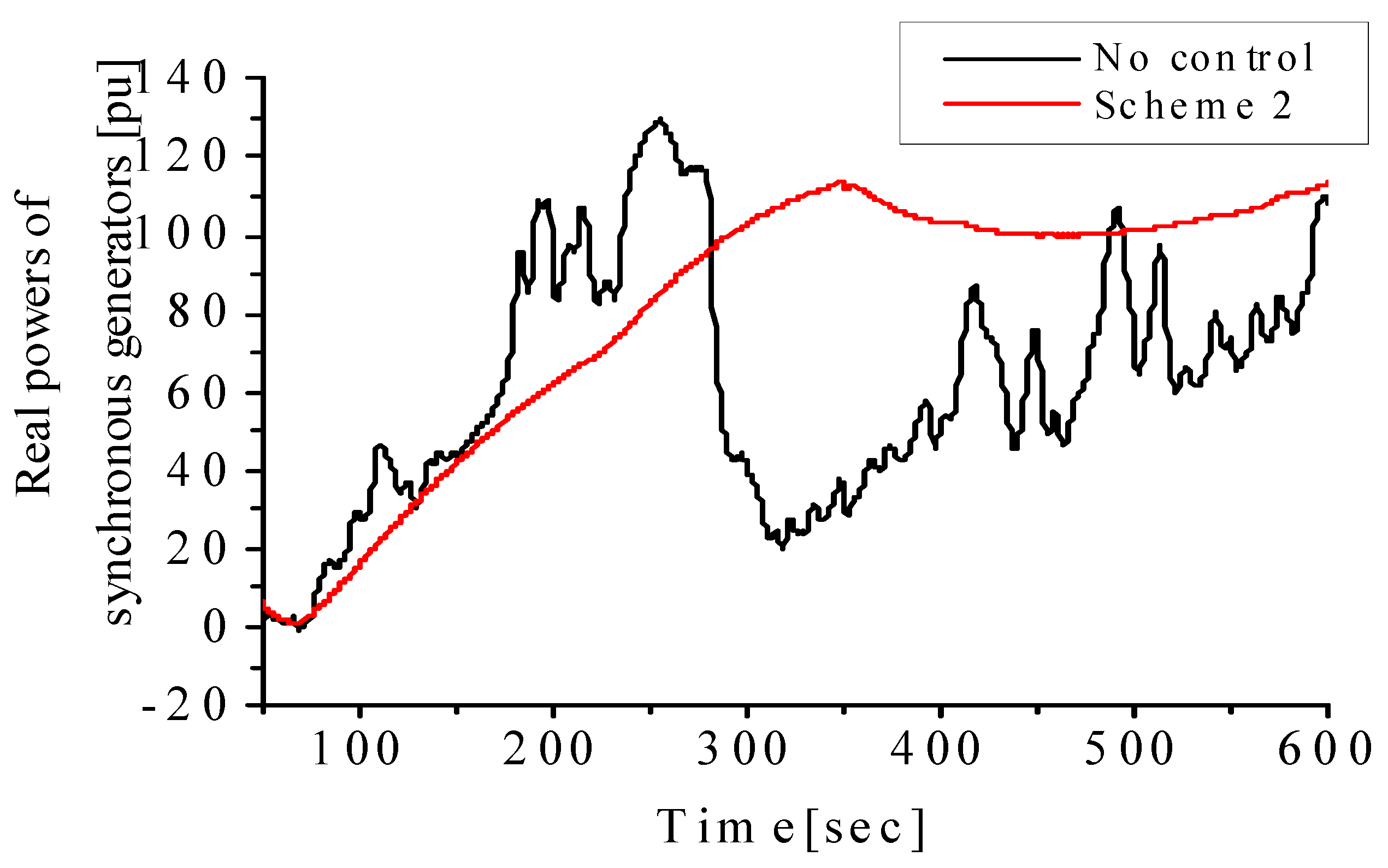
The dynamic responses of the variables of the synchronous generators in the power network are shown in Figure 11 and Figure 12. In Figure 11, the real powers of the steam and hydro synchronous turbines were controlled using the MPPT DFIG Scheme 1 control strategy in wind farm A. In Figure 12, more distortions in the variables of the thermal synchronous turbine were obtained during periods of grid dynamics when no frequency control strategy was implemented in the wind farm connected to the grid network. However, when the ECS scheme in Scheme 2 was employed, an improved response of the steam turbine variable was obtained.
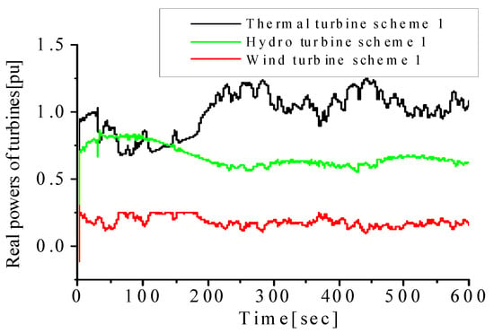
Figure 11.
Real powers of turbine using Scheme 1.
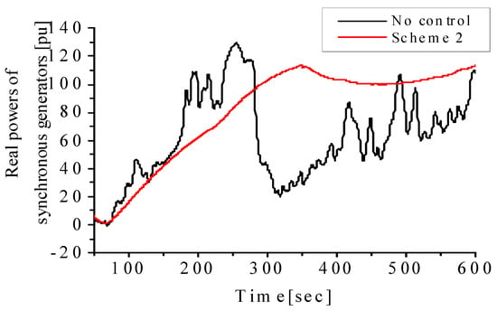
Figure 12.
Real powers of steam turbine using Scheme 2.
However, the grid frequency response was improved using Scheme 1, but the distortions were not totally eliminated. The implementation of Scheme 1 is less expensive than Scheme 2. This is because, apart from stabilizing the grid frequency, Scheme 1 has the additional benefit of generating power to the grid, compared to the expensive external unit of Scheme 2.
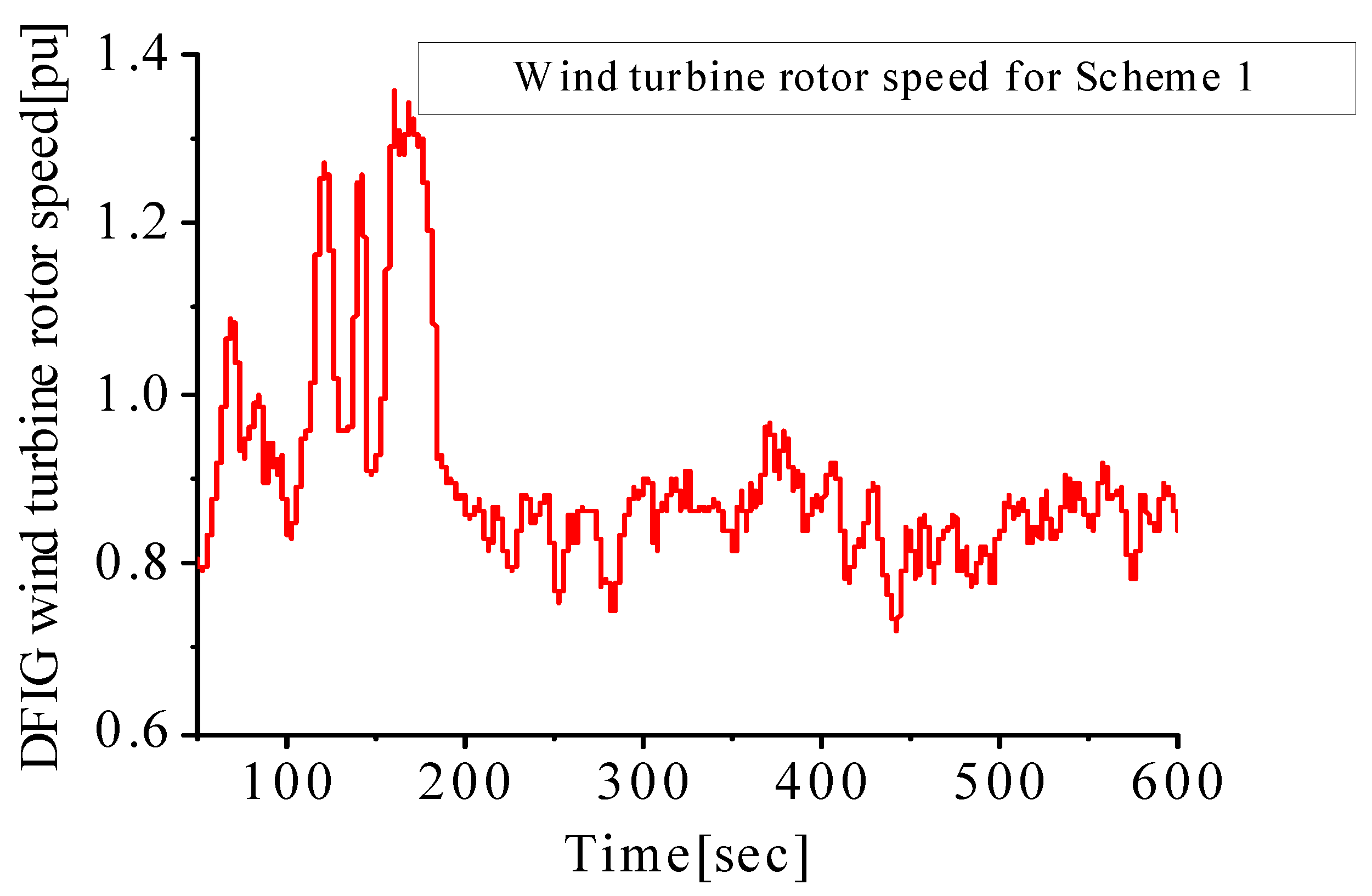
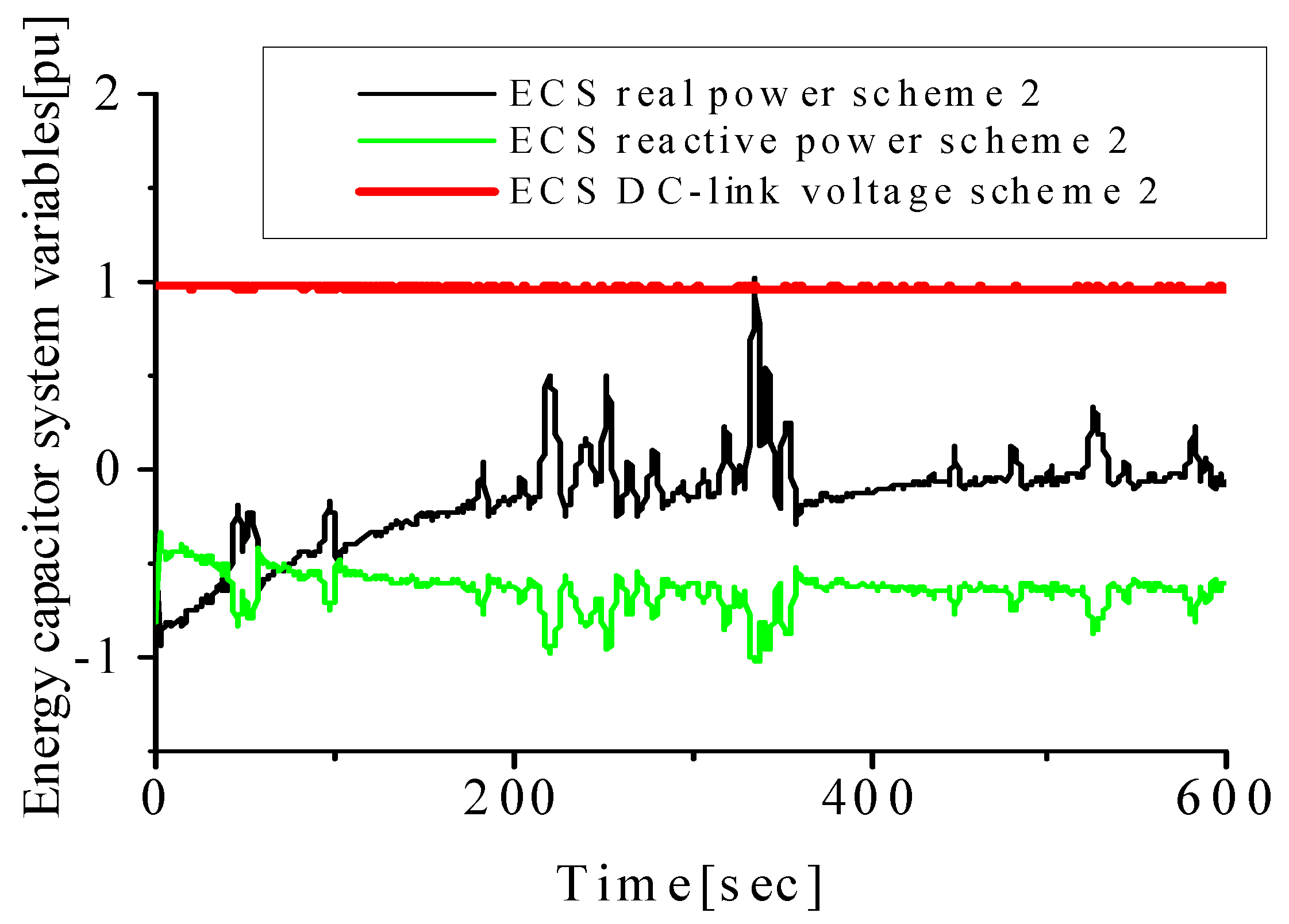
The response of the DFIG variable-speed wind generator rotor speed is shown in Figure 13, where it can be observed that the rotor speed follows the nature of the wind speed with a minimum operation value of 0.7 pu for the lowest wind speed and maximum value of 1.3 pu for the highest wind speed. This is based on the control strategy presented in Figure 2 and Figure 3, respectively, for the DFIG MPPT control scheme in wind farm A. The responses of the energy capacitor system variables during the periods of dynamics are shown in Figure 14. The DC-link voltage of the ECS is maintained at unity during the operation based on the control strategy employed in Figure 5. Additionally, the real and reactive power control to achieve the improved frequency performance of the grid system in Figure 14, based on the wind speed during dynamic periods, is shown in the same figure. The presented results show that the employed controllers used in the schemes are effective.
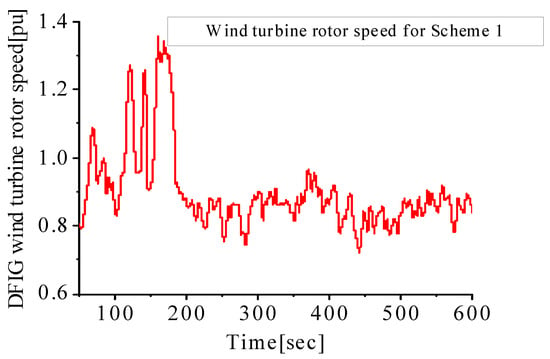
Figure 13.
Wind turbine speed in wind farm A.
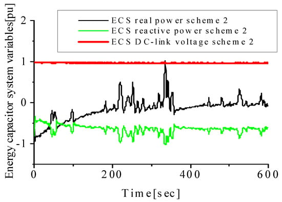
Figure 14.
Energy capacitor variables in wind farm B.
It should be noted that the wind turbine rotor speed in wind farm A, shown in Figure 13, where the minimum and maximum operation rotor speeds are 0.7 pu and 1.3 pu, respectively, is based on the lowest and highest wind speeds. The response of the rotor speed shows that it is tracking the natural wind speed used for the DFIG wind turbine since it has a variable speed of operation in nature. The DC-link voltage of the ECS is kept constant in Figure 14 by the control strategy of wind farm B despite the changes in wind speed. This is necessary in order to inject reactive power into the grid, as shown in Figure 14, for stability improvement of the system. The real and reactive powers of the ECS were also effectively controlled during disturbance using Scheme 2 in wind farm B.
In light of the results presented above, the variable-speed wind turbine incorporated with the flywheel technology and the fixed-speed wind turbine embedded with an energy capacitor system are two possible solutions to mitigate the fluctuations in grid-connected wind farms considering different wind turbine technologies. The main advantage of the earlier scheme is that the variable-speed wind turbine based on DFIG can generate and simultaneously stabilize the wind farm during dynamics owing to the flywheel technology since the active power can be controlled to achieve smoothing of the terminal of the wind farm. In the latter scheme, the fixed-speed wind turbine technology can also generate power, but an external FACTS device utilizing the ECS technology can increase the overall cost of the system compared to the earlier scheme. Therefore, it is suggested to encourage the use of variable-speed wind turbines such as DFIGs embedded with advanced flywheel technology to stabilize grid-connected wind farms during dynamics and mitigate frequency variations within the stipulated grid codes or requirements for the effective operation of power grids by grid operators.
6. Conclusions
The performance of a variable-speed wind turbine that is doubly fed induction generator (DFIG)-based considering a novel control scheme that is based on effective maximum power point tracking and smooth control of the reference power is presented in this paper. This DFIG control strategy uses the excess kinetic energy that is generated and stored based on the nature of available wind speed during dynamics. This scheme is further compared to a scheme using an energy capacitor system control strategy with a fixed-speed wind turbine system. The responses of the grid frequency and other variables of the grid-connected power network show improved performance of the grid frequency during dynamics. However, fewer distortions and better responses based on grid requirements are achieved using the latter scheme. The quantitative summary of the grid frequency response is as follows. With no control implemented, the frequency dip was 47.20 Hz with an overshoot of 50.500 Hz, and the time of recovery was more than 600.00 s. When Scheme 1 was implemented, the frequency dip was 49.99 Hz with an overshoot of 50.005 Hz, and the time of recovery was 0.01 s. When Scheme 2 was implemented, the frequency dip was 49.99 Hz with an overshoot of 50.001 Hz, and the time of recovery was 0.01 s.
The obtained results in the paper show considerable improvements in the power grid frequency compared to those obtained in the literature in references [30,32] with values of 59.42 Hz and 59.44 Hz, respectively, for their proposed schemes that were based on a 60 Hz frequency reference; as reported regarding frequency regulation, using DFIG as a primary frequency stability support is effective based on the concept of a pitch angle controller in settling frequency, frequency nadir, and DFIG-stored kinetic energy in a wind farm topology of maximum power point tracking.
As part of future work, the analysis of a permanent magnet synchronous generator (PMSG) with a flywheel energy system should be carried out using the results obtained here using the DFIG with a flywheel system. The outcome of these would properly guide wind farm developers, stakeholders, power grid operators, and policymakers to know the best variable-speed wind turbine to employ in modern wind farms.
Author Contributions
Conceptualization, K.E.O.; methodology, K.E.O.; software, K.E.O. and A.K; validation, K.E.O.; formal analysis, A.K.; investigation, K.E.O.; resources, A.K.; data curation, K.E.O.; writing—original draft preparation, K.E.O.; writing—review and editing, K.E.O. and A.K.; visualization, A.K.; funding acquisition, A.K. All authors have read and agreed to the published version of the manuscript.
Funding
This APC for this research was funded by the Smart Energy Research Unit, Victoria University, Ballarat Road, Footscray, Victoria, Australia.
Data Availability Statement
The data used in this study are available in the paper.
Conflicts of Interest
The authors declare no conflict of interest.
Nomenclature
| ra | armature resistance (Ω) |
| xa | armature reactance (Ω) |
| Xd | direct axis reactance (Ω) |
| Xq | quadrature axis reactance (Ω) |
| X′d | transient direct axis reactance (Ω) |
| X′q | transient quadrature axis reactance (Ω) |
| X″d | sub-transient direct axis reactance (Ω) |
| X″q | sub-transient quadrature axis reactance (Ω) |
| flywheel rotational speed (m/s) | |
| moment of inertia (kg·m2) | |
| T′do, T″do | direct axis transient and sub-transient time (s) |
| T′qo, T″do | quadrature axis transient and sub-transient time (s) |
| H | inertia (s) |
| maximum speed of the flywheel system (m/s) | |
| minimum speeds of the flywheel system (m/s) | |
| electrical angular velocity ( (m/s) | |
| stator flux linkage (Wb) | |
| magnetizing inductance (H) | |
| stator inductance (H) | |
| conjugate of the rotor current (A) | |
| Psmoothing ref | smoothing reference power (W) |
| Pmaximum | maximum power (W) |
| X/R | reactive power and ohmic ratio |
References
- Wu, B.; Lang, Y.; Zargari, N.; Kouro, S. Power Conversion and Control of Wind Energy Systems, 1st ed.; Wiley-IEEE Press: Hoboken, NJ, USA, 2011; pp. 153–170. [Google Scholar]
- Venkata, B.; Jayaram, P.; Kumar, S.V. Load frequency control for two area interconnected power system using robust genetic algorithm controller. J. Theor. Appl. Inf. Technol. 2008, 4, 1204–1212. [Google Scholar]
- Okedu, K.E. Enhancing the performance of DFIG variable speed wind turbine using parallel integrated capacitor and modified modulated braking resistor. IET Gener. Transm. Distrib. 2019, 13, 3378–3387. [Google Scholar] [CrossRef]
- Wilches-Bernal, F.; Chow, J.H. A fundamental study of applying wind turbines for power system frequency control. In Proceedings of the CFES Annual Conference, Troy, NY, USA, 26 February 2015. [Google Scholar]
- Singh, K.P. Load frequency control of multi-source power system with redox flow batteries: An analysis. Int. J. Comput. Appl. 2014, 88, 46–52. [Google Scholar]
- Kumar, I.; Kothari, D.P. Recent philosophies of automatic generation control strategies in power systems. IEEE Trans. Power Syst. 2005, 20, 346–357. [Google Scholar]
- Okedu, K.E. Enhancing DFIG wind turbine during three-phase fault using parallel interleaved converters and dynamic resistor. IET Renew. Power Gener. 2016, 10, 1211–1219. [Google Scholar] [CrossRef]
- Okedu, K.E. Augmenting DFIG wind turbine transient performance using alternative voltage source T-type grid side converter. Renew. Energy Focus 2017, 18, 1–10. [Google Scholar] [CrossRef]
- Adhikari, S.; Li, F. Coordinated V-f and P-Q control of solar photovoltaic generators with MPPT and battery storage in micro grids. IEEE Trans. Smart Grid 2014, 5, 1270–1281. [Google Scholar] [CrossRef]
- Serban, I.; Marinescu, C. Control strategy of three-phase battery energy storage systems for frequency support in micro grids and with uninterrupted supply of local loads. IEEE Trans. Power Electron. 2014, 29, 5010–5020. [Google Scholar] [CrossRef]
- Molina, M.G.; Mercado, P.E. Power flow stabilization and control of microgrid with wind generation by superconducting magnetic energy storage. IEEE Trans. Power Electron. 2011, 26, 910–922. [Google Scholar] [CrossRef]
- Ngamroo, I.; Karaipoom, T. Improving low-voltage ride-through performance and alleviating power fluctuation of DFIG wind turbine in DC microgrid by optimal SMES with fault current limiting function. IEEE Trans. Appl. Supercond. 2014, 24, 5700805. [Google Scholar] [CrossRef]
- Okedu, K.E. Enhancing the Transient Performance of DFIG Wind Turbine with Supercapacitor Control Strategy. In Proceedings of the 2022 IEEE 31st International Symposium on Industrial Electronics (ISIE), Anchorage, AK, USA, 31 May–3 June 2022; Paper ISIE22-000118. Volume 31, pp. 92–97. [Google Scholar]
- Inthamoussou, F.A.; Pegueroles-Queralt, J.; Bianchi, F.D. Control of a super-capacitor energy storage system for microgrid applications. IEEE Trans. Energy Convers. 2013, 28, 690–697. [Google Scholar] [CrossRef]
- Ghazanfari, A.; Hamzeh, M.; Mokhtari, H.; Karimi, H. Active power management of multihybrid fuel cell/supercapacitor power conversion system in a medium voltage microgrid. IEEE Trans. Smart Grid 2013, 3, 1903–1910. [Google Scholar] [CrossRef]
- Islam, F.; Al-Durra, A.; Muyeen, S.M. Smoothing of wind farm output by prediction and supervisory-control-unit-based FESS. IEEE Trans. Sustain. Energy 2013, 4, 925–933. [Google Scholar] [CrossRef]
- Suvire, G.O.; Molina, M.G.; Mercado, P.E. Improving the integration of wind power generation into AC microgrids using flywheel energy storage. IEEE Trans. Smart Grid 2012, 3, 1945–1954. [Google Scholar] [CrossRef]
- Sebastián, R.; Peña Alzola, R. Flywheel energy storage systems: Review and simulation for an isolated wind power system. Renew. Sustain. Energy Rev. 2012, 16, 6803–6813. [Google Scholar] [CrossRef]
- Jerbi LKrichen Ouali, A. A fuzzy logic supervisor for active and reactive power control of a variable speed wind energy conversion system associated to a flywheel storage system. Electr. Power Syst. Res. 2009, 79, 919–925. [Google Scholar] [CrossRef]
- Zhang, Y.; Liu, X.; Qu, B. Distributed model predictive load frequency control of multi-area power system with DFIGs. IEEE/CAA J. Autom. Sin. 2017, 4, 125–135. [Google Scholar] [CrossRef]
- Okedu, K.E. A variable speed wind turbine flywheel based coordinated control system for enhancing grid frequency dynamics. Int. J. Smart Grid 2018, 2, 123–134. [Google Scholar]
- Wang, L.; Yu, J.; Chen, Y.T. Dynamic stability improvement of an integrated offshore wind and marine-current farm using a flywheel energy-storage system. Renew. Power Gener. 2011, 5, 387–396. [Google Scholar] [CrossRef]
- Huang, L.; Xin, H.; Zhang, L.; Wang, Z.; Wu, K.; Wang, H. Synchronization and frequency regulation of DFIG-based wind turbine generators with synchronized control. IEEE Trans. Energy Convers. 2017, 32, 1251–1262. [Google Scholar] [CrossRef]
- Liu, Y.; Jiang, L.; Wu, Q.; Zhou, X. Frequency control of DFIG-based wind power penetrated power systems using switching angle controller and AGC. IEEE Trans. Power Syst. 2016, 32, 1553–1567. [Google Scholar] [CrossRef]
- Ananth, D.V.; Kumar, G.V.N.; Chowdary, D.D.; Naidu, K.A. Two area load frequency control for DFIG-based wind turbine system using modern energy storage devices. Int. J. Pure Appl. Math. 2017, 114, 113–123. [Google Scholar]
- Gu, W.; Liu, W.; Wu, Z.; Zhao, B.; Chen, W. Cooperative control to enhance the frequency stability of islanded microgrids with DFIG-SMES. Energies 2013, 6, 3951–3971. [Google Scholar] [CrossRef]
- Okedu, K.E.; Muyeen, S.M.; Takahashi, R.; Tamura, J. Wind Farm Stabilization by using DFIG with Current Controlled Voltage Source Converters Taking Grid Codes into Consideration. IEEJ Trans. Power Energy 2012, 132, 251–259. [Google Scholar] [CrossRef]
- Okedu, K.E. Effect of ECS low pass filter timing on grid frequency dynamics of a power network considering wind energy penetration. IET Renew. Power Gener. 2017, 11, 1194–1199. [Google Scholar] [CrossRef]
- Attya, A.B.; Dominguez-Garcia, J.L.; Anaya-lara, O. A Review on Frequency Support Provision by Wind Power Plants: Current and Future Challenges. Renew. Sust. Energ. Rev. 2018, 81, 2071–2087. [Google Scholar] [CrossRef]
- Xiuli, S.; Xiaoxin, W.; Feng, Y.; Hongliang, Y.; Yien, X.; Dejian, Y. Primary Frequency Stability Support of a DFIG in Association with Pitch Angle Control. Front. Energy Res. 2022, 9, 798037. [Google Scholar] [CrossRef]
- Aziz, A.; Oo, A.T.; Stojcevski, A. Frequency Regulation Capabilities in Wind Power Plant. Sustain. Energ. Technol. Assess. 2018, 26, 47–76. [Google Scholar] [CrossRef]
- Dejian, Y.; Shun, S.; Xinsong, Z. Two-Phase Short-Term Frequency Response Scheme of a DFIG-Based Wind Farm. Front. Energy Res. 2021, 9, 781989. [Google Scholar] [CrossRef]
- Shi, Q.; Li, F.; Cui, H. Analytical Method to Aggregate MultiMachine SFR Model with Applications in Power System Dynamic Studies. IEEE Trans. Power Syst. 2018, 33, 6355–6367. [Google Scholar] [CrossRef]
- Shi, Q.; Liu, L.; Wang, Y.; Lu, Y.; Zou, Q.; Zhang, Q.; Liu, H. Cooperative Synthetic Inertia Control for Wind Farms Considering Frequency Regulation Capability. Front. Energy Res. 2021, 9, 738857. [Google Scholar] [CrossRef]
- Kim, J.; Muljadi, E.; Gevorgian, V.; Hoke, A.F. Dynamic Capabilities of an Energy Storage-Embedded DFIG System. IEEE Trans. Ind. Applicat. 2019, 55, 4124–4134. [Google Scholar] [CrossRef]
- PSCAD/EMTDC Manual; Manitoba HVDC Research Center: Winnipeg, MB, Canada, 2006.
- Okedu, K.E.; Muyeen, S.M.; Takahashi, R.; Tamura, J. Wind farms fault ride through using DFIG with new protection scheme. IEEE Trans. Sustain. Energy 2012, 3, 242–254. [Google Scholar] [CrossRef]
- Okedu, K.E.; Muyeen, S.M.; Takahashi, R.; Tamura, J. Protection schemes for DFIG considering rotor current and DC-link voltage. In Proceedings of the 24th IEEE—ICEMS (International Conference on Electrical Machines and System), Beijing, China, 20–23 August 2011; pp. 1–6. [Google Scholar]
- Mitsuru, S.; Ikuo, T.; Junichi, S.; Takashi, S. Development of 5-MW Offshore Wind Turbine and 2-MW Floating Offshore Wind Turbine Technology. Hitachi Rev. 2014, 63, 414–421. [Google Scholar]
- Genta, G. Application of Flywheel Energy Storage System in Kinetic Energy Storage: Theory and Practice of Advanced Flywheel Systems; Butterworth: London, UK, 1985; pp. 27–46. [Google Scholar]
- Yazdani, A.; Iravani, R. Voltage-Sourced Converters in Power Systems: Modeling, Control and Applications, 1st ed.; Wiley-IEEE Press: Hoboken, NJ, USA, 2010; pp. 204–245. [Google Scholar]
- Thai-Thanh, N.; Hyeong-Jun, Y.; Hak-Man, K. A flywheel energy storage system based on a doubly fed induction machine and battery for microgrid control. Energies 2015, 8, 5074–5089. [Google Scholar]
- Okedu, K.E. Smoothing of Wind Farms for Frequency Regulation using DFIG Flywheel and FACTS Strategies. In Proceedings of the 2022 IEEE 31st International Symposium on Industrial Electronics (ISIE), Anchorage, AL, USA, 31 May–3 June 2022; Paper ISIE22-000120. Volume 31, pp. 442–447. [Google Scholar]
- Krause, P.; Wasynczuk, O.; Sudhoff, S.; Pekarek, D. Analysis of Electric Machinery and Drive Systems, 3rd ed.; Wiley-IEEE Press: Hoboken, NJ, USA, 2013; pp. 215–267. [Google Scholar]
Disclaimer/Publisher’s Note: The statements, opinions and data contained in all publications are solely those of the individual author(s) and contributor(s) and not of MDPI and/or the editor(s). MDPI and/or the editor(s) disclaim responsibility for any injury to people or property resulting from any ideas, methods, instructions or products referred to in the content. |
© 2023 by the authors. Licensee MDPI, Basel, Switzerland. This article is an open access article distributed under the terms and conditions of the Creative Commons Attribution (CC BY) license (https://creativecommons.org/licenses/by/4.0/).

