Article

Numerical Investigation of Compression and Expansion Process of Twin-Screw Machine Using R-134a

1
Department of Mechanical Engineering, National Yang Ming Chiao Tung University, Hsinchu 300093, Taiwan
2
Fu Sheng Industrial Co., Ltd., New Taipei City 241020, Taiwan
3
Green Energy and Environment Research Laboratories, Industrial Technology Research Institute, Hsinchu 310401, Taiwan
*
Author to whom correspondence should be addressed.
Energies 2023, 16(8), 3599; https://doi.org/10.3390/en16083599
Submission received: 2 March 2023 / Revised: 12 April 2023 / Accepted: 17 April 2023 / Published: 21 April 2023

Abstract

:
Increasing the efficiency of twin-screw machines is beneficial for gas compression and expansion applications. We used a computation fluid dynamic approach to obtain the flow field and efficiency of a twin-screw machine that used R-134a as the working fluid. The leakage flow and sealing lines were obtained to study their geometrical effects during the compression and expansion process. The effects of the wrap angle (280°, 290°, and 300°) and pressure ratios on the compression efficiency were studied. During the compression process, the volumetric efficiency was more than 70% regardless of the wrap angle. We found that the volumetric efficiency slightly decreased when the wrap angle increased. However, the effect of the wrap angle on the isentropic efficiency was not substantial. An increase in the pressure ratio decreased the mass flow rate and increased the leakage flow. This screw machine can also be operated in an expansion process, and the simulated expansion ratio was 3:1. However, this expansion ratio contributed to an underexpanded condition, which led to a lower volumetric and isentropic efficiencies compared with the original built-in expansion ratio scenario.

1. Introduction

Twin-screw compressors have a high reliability, are easy to maintain, and have a favorable dynamic balance, and they are commonly used in gas and refrigeration applications. The main components of twin-screw compressors are male and female rotors, and the volume sealed between the rotors changes as the rotor rotates, which leads to pressure variations. Therefore, the size and geometry of the helical-lobed rotors dictate the pressure ratio and efficiency of the screw compressors.
The rotor profile should be designed to minimize the leakage flow while attaining the maximal flow area in the screw chamber. To achieve this goal, the mathematical model of the rotor typically considers the influences from the fluid flow, compressor layout, and thermodynamics properties [1,2]. Stošić et al. [3] proposed a new rotor profile for twin-screw compressors, and its power input requirement was lower than that of other commercially available compressors. For a pressurized process of up to 8 bar, the required power input is 5.6 kW·m−3·min−1. You et al. [4] discovered that the geometrical parameters of a rotor, such as the lobe combination, length-to-diameter ratio, and wrap angle, have a noticeable effect on the compressor performance. A lobe combination of 5/6 contributed to the highest overall performance, although it may lead to female rotor deflection if operated in high-pressure conditions. In addition, the peak isentropic efficiency was observed at a wrap angle of 325° for all the lobe combinations. Furthermore, the optimization of the profile design and advancement of the rotor manufacturing can increase the competitiveness of the screw compressors [5]. For this oil-injected compressor, an increase in the rotational speed decreased the flow leakage and increased the volumetric efficiency. In addition, the volumetric efficiency was influenced by the injected oil temperature and injection angle. Lee et al. [6] found that the compressor efficiency increased with the injection temperature until an optimum oil temperature was reached.
To increase the compressor efficiency, the variable lead rotors generated a greater discharge area than the constant lead rotors, which can reduce the throttling losses in the discharge port as mentioned by Rane et al. [7]. For a given rotor length, the wrap angle can be specified according to the variable rotor lead. The rotor lead is typically defined as the axial advance of the helix of the rotor in one full revolution. Utri and Brümmer [8] concluded that the dual lead rotors successfully increased the compressor efficiency of refrigeration applications. When the wrap angles were in the optimal range of 300° to 400°, a lobe combination of 4/6 resulted in the highest isentropic efficiency of 88%, whereas a lobe combination of 3/5 resulted in the highest delivery rate.
Preliminary designs of screw compressors have generally relied on one-dimensional mathematical and theoretical models. As the computational fluid dynamics (CFD) advance, scholars could utilize this tool when designing the compressor in order to conduct more accurate parametric studies and performance evaluations. Despite the authors of numerous studies using CFD, numerically predicting the screw compressor is still challenging and scarce because of the geometrical complexity within the lobed rotors [9]. Particularly, the dimension and geometry experience substantial changes during the compression process, and the stretching and shrinking of the fluid domain complicates the generation of high-quality dynamic meshes. Therefore, a specific grid generation method should be applied to resolve this issue, such as the SCORG (screw compressor rotor grid generator) [10]. The computational meshes were generated on the meshes in the vicinity of the male and female rotors, and the grid orthogonality and smoothness were assured by using the appropriate transfinite interpolation and stretching function. These generated grids can be imported into the commercial software ANSYS-CFX to numerically investigate the screw compressors [11]. The grids generated by using the SCORG can be used to numerically model oil-injected screw compressors, and the oil and gas distribution can be visualized in the compression chamber [12]. Another grid generator, TwinMesh, can produce dynamic meshes for positive displacement machines [13]. The effects of the control edge, throttling, chamber refilling, and leakage flow can be numerically studied, and the results are comparable to experimental measurements. The twin-screw compressor was also favorable for refrigerant compression [14,15]. For oil-injected compressors, the oil injection method was studied to optimize the energy efficiency. The distribution of the velocity, pressure, and temperature in the internal chamber of the compressor was useful when analyzing the compressor efficiency and performance.
The screw compressor can be conveniently modified into an expander by reversing the rotor rotation direction, which thus transports the working fluid from the high to low-pressure port. The single screw expander can be applied for the low-temperature waste-heat recovery process because it has the advantages of low leakage, noise, and vibration and a long working life [16]. Particularly, the screw expander has been frequently used in the organic Rankine cycle (ORC) for heat recovery. Compared with typical turbine expanders, the volumetric expanders are more suitable for small-scale power generation [17]. Papes et al. [18] conducted a numerical analysis on the use of twin-screw expanders for small-scale ORC applications using refrigerant R245fa. They found that the highest pressure losses were caused by the throttling loss at the inlet; therefore, optimizing the design of the inlet port could be beneficial. An oil-less twin-screw expander was numerically studied by using ANSYS-CFX, and the grids were generated by using TwinMesh [19]. The numerical results were compared by using the experimental data as the pressure changed from 4 to 1 bar during the expansion process. To account for the change in the fluid properties of the twin-screw expander, a real gas equation of state was applied to replace the use of the REFPROP database [20]. This approach saved more computational time, and the difference in the computed results was insignificant (<2.2%).
We studied both the compression and expansion process of an oil-less twin-screw machine. First, the compressor mode was numerically studied, and the mass flow rate, pressure, temperature, and efficiency were reported. In addition, the effect of the wrap angle and pressure ratio on the compressor performance was studied. Reducing the leakage flow is beneficial for increasing the operational efficiency; additionally, achieving a shorter sealing line and smaller blow-hole area is desirable. Afterward, this screw-type machine was converted into an expander by reversing the rotation direction, and the performance was evaluated and compared.

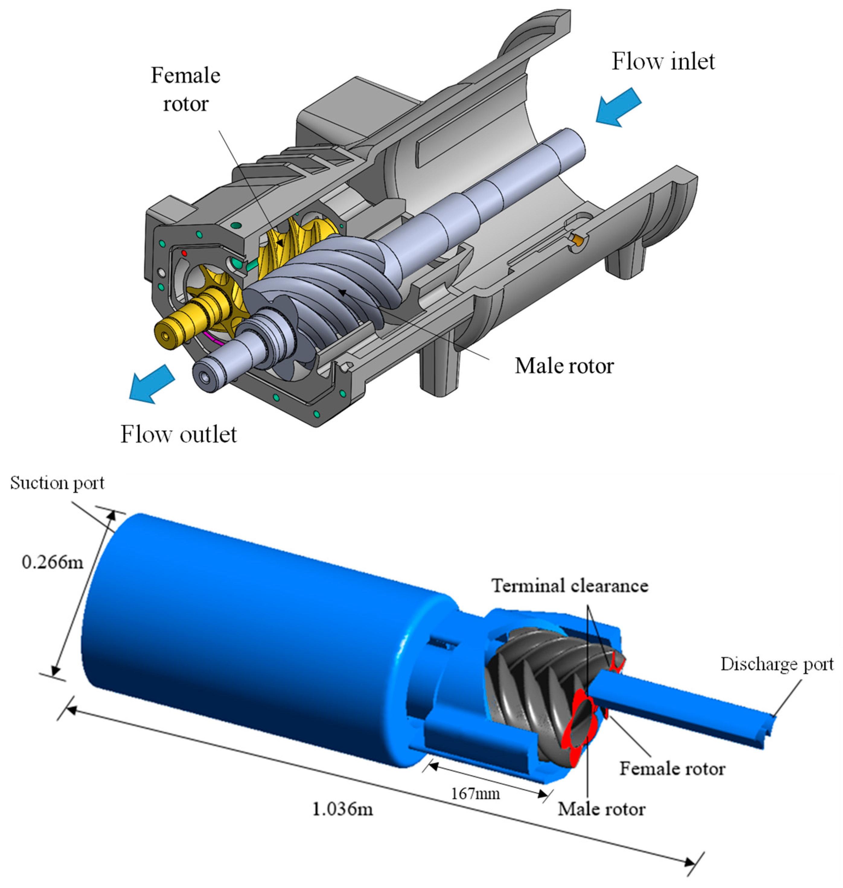
2. Geometric Modeling and Meshing

We used an oil-less twin-screw machine to study refrigerant compression and expansion, and this type of positive displacement machine exhibited a complex geometry, as shown in Figure 1. To simulate the operation process, four primary computational domains were constructed; namely, the high- and low-pressure side, the casing, and the lobed rotor section. During the compression process, the fluid inlet was located in the low-pressure suction port, and the volume of the compression chamber varied as the lobed rotor rotated. The suction and discharge ports were arranged in an axial manner. The high-pressure fluid compressed by the rotors was discharged through the high-pressure outlet port. To enhance the numerical stability, the discharge port at the outlet of the rotor was elongated.
The lobe combination of the rotor was 5/6 and the rotor profile was provided by Fusheng industries. The male rotor had five lobes, a 138.54 mm outer diameter, and the designated wrap angle was 290°. The female rotor had six lobes and the outer diameter was 109.86 mm. The geometrical parameters of the screw machine are listed in Table 1. The interlobe and radial clearances between the lobe and casing were 0.06 mm and 0.04 mm, respectively. Two additional wrap angles (280° and 300°) were tested by maintaining the same rotor length of 167 mm. The wrap angle is defined as the degree of twist between the front and the rear surface of the male rotor [8]. The sketch of the wrap angle of the rotor is shown in Figure 2.

3. Simulation Settings

3.1. Governing Equations and Boundary Conditions

ANSYS-CFX [21] was used for the flow simulations, and this commercial software is based on a finite-volume solver. Conservation equations of mass, momentum, and energy were solved. When conducting our numerical simulation, we considered a three-dimensional, unsteady, and compressible flow. The detailed governing equations can be found in the ANSYS-CFX manual [21]. In general, transient simulations are frequently used for positive displacement machines, particularly for the expanders or compressors of twin-screws. The internal volume changes when the machine is operating. During the simulation, the dynamic mesh was used to account for the boundary motion caused by the rotors. The motion of the dynamic mesh was described by using the angular velocity of the rotor, and the mesh was updated according to the 5/6 lobe combinations.
The compressor was operated under turbulent flow conditions; therefore, a turbulence model was applied, and the turbulence transport equations were also solved. The k-omega shear stress transport turbulence model (SST model), which combines the advantages of different turbulence models, was implemented in the computation and was viable for the screw-compressor simulation. For the R134a working fluid, the real gas model (Aungier–Redlich–Kwong) was employed to obtain the refrigerant property. This model was considered an improvement over the traditional ideal gas model. Based on the literature survey [20,22], this model is appropriate to use when estimating the refrigerant properties in the screw compressor, and it reduces the computational time. The adiabatic boundary condition was employed on the external wall; therefore, the heat lost to the surroundings was excluded in the computation.
The volumetric and isentropic efficiencies are commonly used to evaluate the performance of twin-screw compressors. The volumetric efficiency is defined as the ratio of the actual flow rate to the ideal flow rate delivered by the compressor. The ideal flow rate can be determined by using the geometrical parameters of the rotor profile. The isentropic efficiency of the compressor was calculated by using the ratio of the actual work input and the work input during the isentropic process. The inlet and outlet boundary conditions were enacted at the ports, which were openings where the fluid could move in and out of the chamber. A personal computer (Intel i9-1040X, 256GB RAM) was used for the computations, and the computational time for each revolution was approximately 35 h. The boundary conditions and the test parameters for the compression and expansion processes are summarized in Table 2.

3.2. Meshing of the Fluid Domains

Meshes of the stationary and moving parts of the screw machines were generated separately. The suction and discharge port and the casing were stationary, and those meshes were generated using ANSYS, as shown in Figure 3. To reduce the backflow problem, the discharge port was elongated during the compression process. Because of the complexity and skewed nature of the geometry, the tetrahedral and hexahedral meshes were employed to achieve a stronger connectivity between the fluid domains. Because of the small clearances within the rotors, the high-quality dynamic meshes were required to resolve the rotation motion and the extension and shrinkage issues in the flow area. TwinMesh was used to generate the meshes for the male and female lobed rotors. Using a minimum of 20 layers along the radial direction is recommended to reduce the grid skewness [15]; therefore, 40 layers were used for the current rotor boundary. The interface between the stationary and rotating parts were connected using the same grid size (1.5 mm) as recommended by previous authors [22], and this controlled the skewness of the stationary grids (<0.79). The grid-quality check was also conducted to satisfy the requirements of the ANSYS, including the minimum angle, aspect ratio, and skewness.

3.3. Grid Independence Verification

A grid independence study was conducted to ensure that the number of mesh points was sufficient for the simulation. The number of computational grid points ranged from 5.5 to 8.5 million. The predicted mass flow rate and power were compared. We found that the grid independence was achieved when the number of grid points was higher than 7.0 million, as demonstrated in Figure 4. To save computational time, we used 7.0 million grids for all the simulation cases. The computed results were also compared to the experimental data provided by the manufacturer, and the difference was about 6.4%.

4. Simulation Results

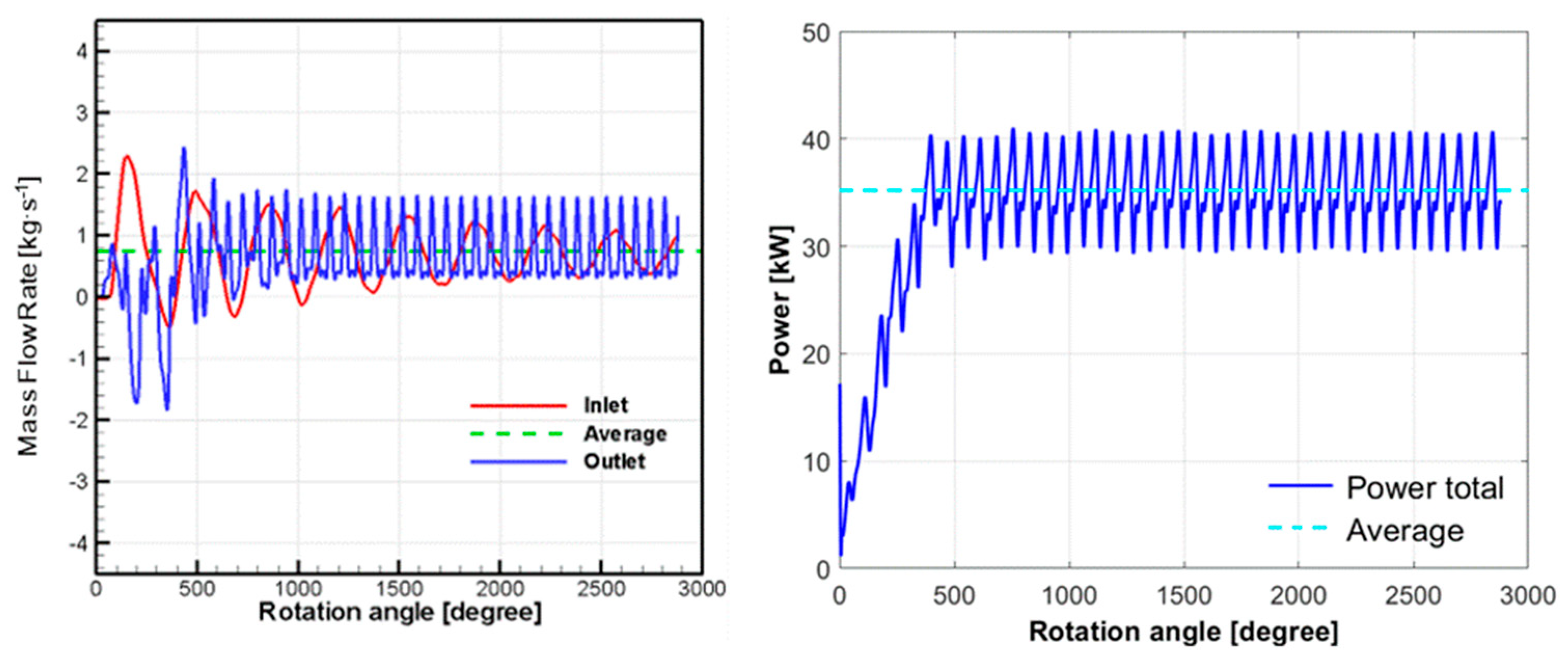
4.1. Twin-Screw Compressor

The geometrical parameters and operating conditions had a noticeable effect on the compressor performance. The pressure and flow distribution in the compression chamber can be used to evaluate the compressor efficiency. The transient simulation was conducted for eight rotor revolutions (2880°), after which the compressor reached a stable fluctuating condition. The predicted inlet and outlet mass flow rates at a wrap angle of 290° are presented in Figure 5. In the initial stage, large fluctuations in the mass flow rate were observed, and the mass flow rate gradually converged to a periodically stable value after six revolutions. The outlet constantly opened and closed during the real situation, which generated a stronger fluctuation in the mass flow rate. Consequently, the average mass flow rate in each revolution reached a stable value as more revolutions were reached. Therefore, the computed results after six revolutions were used to evaluate the compressor performance. According to the average mass flow rate over one revolution, the difference between the inlet and outlet values were approximately 1.6%. This was primarily caused by the relatively coarse meshes at the sliding interface between the lobed rotors and the large aspect ratio meshes in the clearance gap [23]. Although the accuracy could be increased by using more revolutions, the difference between the inlet and outlet mass flow was still expected based on the literature [24,25,26]. The shaft power was calculated by using the torque generated by the rotors, and the overall power input required was 35.2 kW.
The pressure distribution on the rotor surface after seven revolutions at a pressure ratio of 3.17 is shown in Figure 6. These results were presented at several rotation angles during one revolution. For a converged solution, the time-resolved results should produce a periodic pattern over a section of 72° due to the periodicity of the rotors. The air entered the compressor at a pressure of 2.5 bar, and the pressure increased along the axial direction. The pressure variation was related to the volume change in the compression chamber during the rotation, and the pressure peaks were reached before the flow left the screw section.
Figure 7 shows the sealing line on the screws that separated the suction and discharge sides. The sealing lines were constructed by connecting the continuous contact points between the male and female screws during the rotation. A shorter sealing line reduced the leakage flow and had a strong impact on the rotor efficiency. The sealing line at different wrap angles is presented in Figure 8, and the sealing lines were almost identical near the suction port (Z = 0). However, as the pressure increased, the wrap angles altered the location and length of the sealing lines, which led to a different flow delivery. From the current rotor profile, the sealing line length was shortened at the suction port, and the length increased toward the discharge port.
For the twin-screw compressor, the leakage flow occurred in the housing clearances and the front gaps, and the interclearances between the rotors were remarkable [13]. Figure 9 demonstrates the leakage flow from the interface between the male and female rotors. The flow was accelerated as it passed through the small gap, and the velocity was higher than 100 m·s−1. High velocities were primarily observed at the interface and hosing gaps. The leakage flow from the housing clearance was plotted, and it was primarily caused by the pressure difference in the axial direction. According to this figure, the leaking flow near the suction port was not strong. The high-velocity leakage flow was observed near the discharge port because of the increased pressure difference. This leakage flow could lead to backflow problems when the discharge pressure is less than the outlet pressure boundary condition and an increase in the required power input occurs.
The temperature of the working fluid increased as the pressure increased during the compression process, as indicated in Figure 10. The high gas temperature regions only formed in the high-pressure region and were primarily caused by the highly compressed volume. This finding is consistent with the literature [27]. In addition, the fluid temperature could be further increased by the accumulation of the leakage flow in the compression chamber. For the oil-injected compressor, the temperature distribution was a reliable reference when determining the injection location.
Table 3 shows the effect of the wrap angle on the mass flow rate, required power input, and efficiency. The mass flow rate was affected by the variation in the wrap angle, up to 1.7%. This was mainly caused by the displacement of the sealing lines, which led to a different leakage flow. An increase in the wrap angle also decreased the required power input. However, the volumetric efficiency decreased from 75% to 72% as the wrap angel increased from 280°to 300°, and this trend was consistent with the literature data [4]. An increase in the wrap angle also led to a larger leakage flow and reduced the volumetric efficiency. Regarding the isentropic efficiency, it typically increased with the wrap angle until an optimum value was reached, and then it decreased. However, the variation in the isentropic efficiency was less than 1% as the wrap angle increased from 270° to 350° [4]. We found that the wrap angle did not have a strong effect on the isentropic efficiency.
The effects of the pressure ratios (3.16 and 4) were also studied while the other boundary and operating conditions were maintained. As the pressure ratio increased up to 4.0, the delivery flow rate was reduced down to 0.619 kg·s−1, as shown in Figure 11. Regarding the outlet mass flow rate, an increase in the pressure ratio did not cause undercompression even though a larger leakage flow was experienced, which also resulted in a lower volumetric efficiency of 69.7%. A power input that was approximately 15% higher was required for the high-pressure-ratio case. However, the effect of the pressure ratio on the isentropic efficiency was not substantial.

4.2. Twin-Screw Expander

This screw machine was operated as an expander by reversing the rotational direction of the rotors. The expansion ratio was three and the boundary conditions were as listed in Table 2. To avoid a phase change during the expansion process, the inlet and outlet flow were maintained at a superheated state. Figure 12 shows the mass flow fluctuation during the process, and this fluctuation reached a stable pattern after five revolutions. In the expander, the screw motion had little impact on the upstream inlet flow; therefore, the inlet flow fluctuation was not substantial. Unlike the compression mode, the fluid was driven by the rotary motion of the screw, and the flow fluctuation was experienced at both the inlet and outlet. The outlet mass flow became negative at certain angles, which indicated that the backflow was encountered. The averaged inlet and outlet mass rates were 0.25 kg·s−1 and 0.24 kg·s−1, respectively. The difference was primarily caused by the leakage flow and backflow.
The pressure distribution at different angles is shown in Figure 13. Because the built-in expansion ratio was approximately seven, the screw expander experienced an underexpanded condition. In this scenario, the pressure was gradually decreased and the minimum pressure was smaller than the outlet pressure. Afterward, the pressure gradually increased after the fourth and fifth screw until the pressure recovered to the outlet pressure level. The pressure fluctuation was not substantial in the discharge and suction ports.
The leakage flow is plotted in Figure 14, and primary leakage spots are marked by red rectangles. These leakage spots were mainly observed at the front gap, rotor-tip housing, and interlobe gaps. The high-velocity leakages, above 150 m·s−1, were found within the front and interlobe gaps. The leakage flow through the blow hole can also be observed, and this was mainly caused by the pressure difference between the high- and low-pressure working chambers in the axial direction. The leakage flow through the blow hole was a jet of fluid ejected from the high-pressure chamber to the low-pressure side. This leakage flow and the underexpanded conditions had a detrimental effect on the efficiency of the screw expander. The volumetric and isentropic efficiencies were 69.2% and 42.5%, respectively.

5. Conclusions

A numerical study was conducted to evaluate the feasibility of using a twin-screw machine for both compression and expansion processes. The effects of different wrap angles (280°, 290°, and 300°) and pressure ratios (3.16 and 4) were studied. The flow field, pressure, and temperature distributions were determined for the male and female rotors. The volumetric and isentropic efficiencies were also calculated by using the simulated results. The conclusions can be summarized as follows:
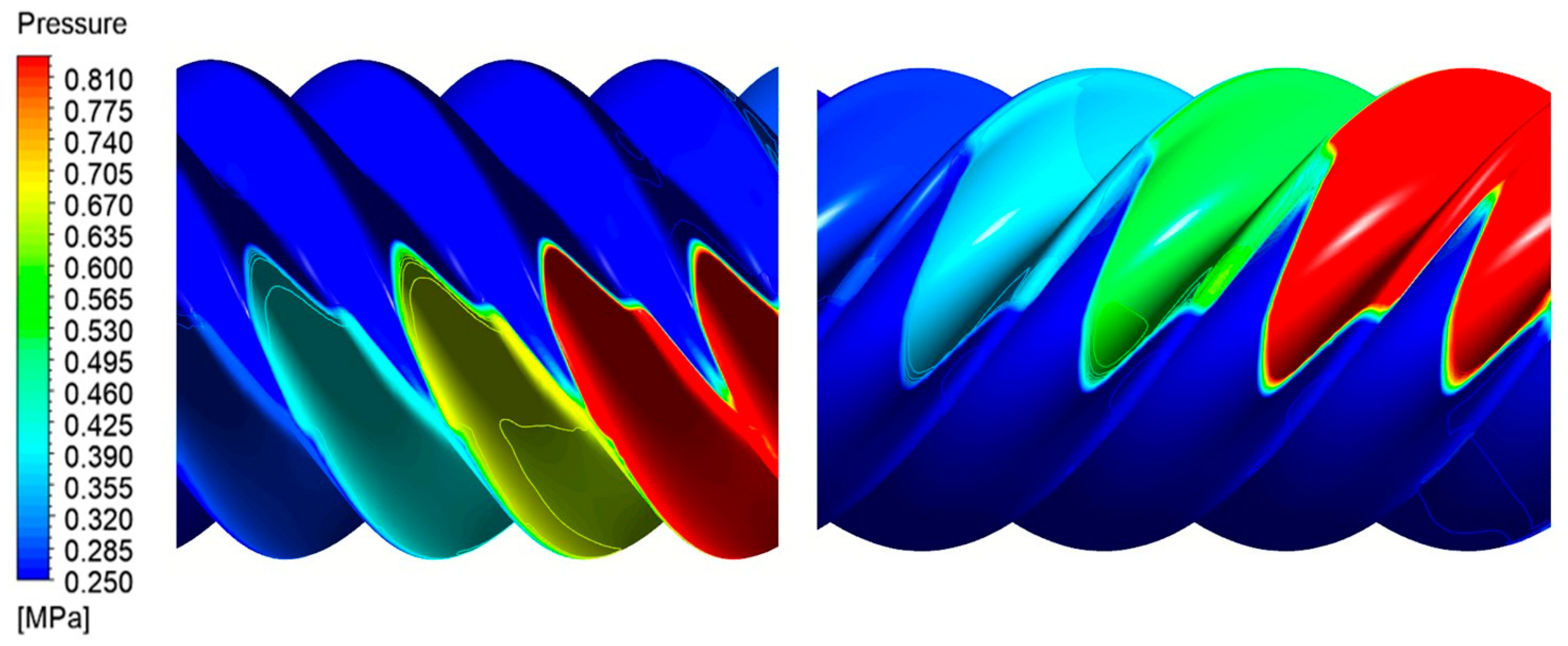
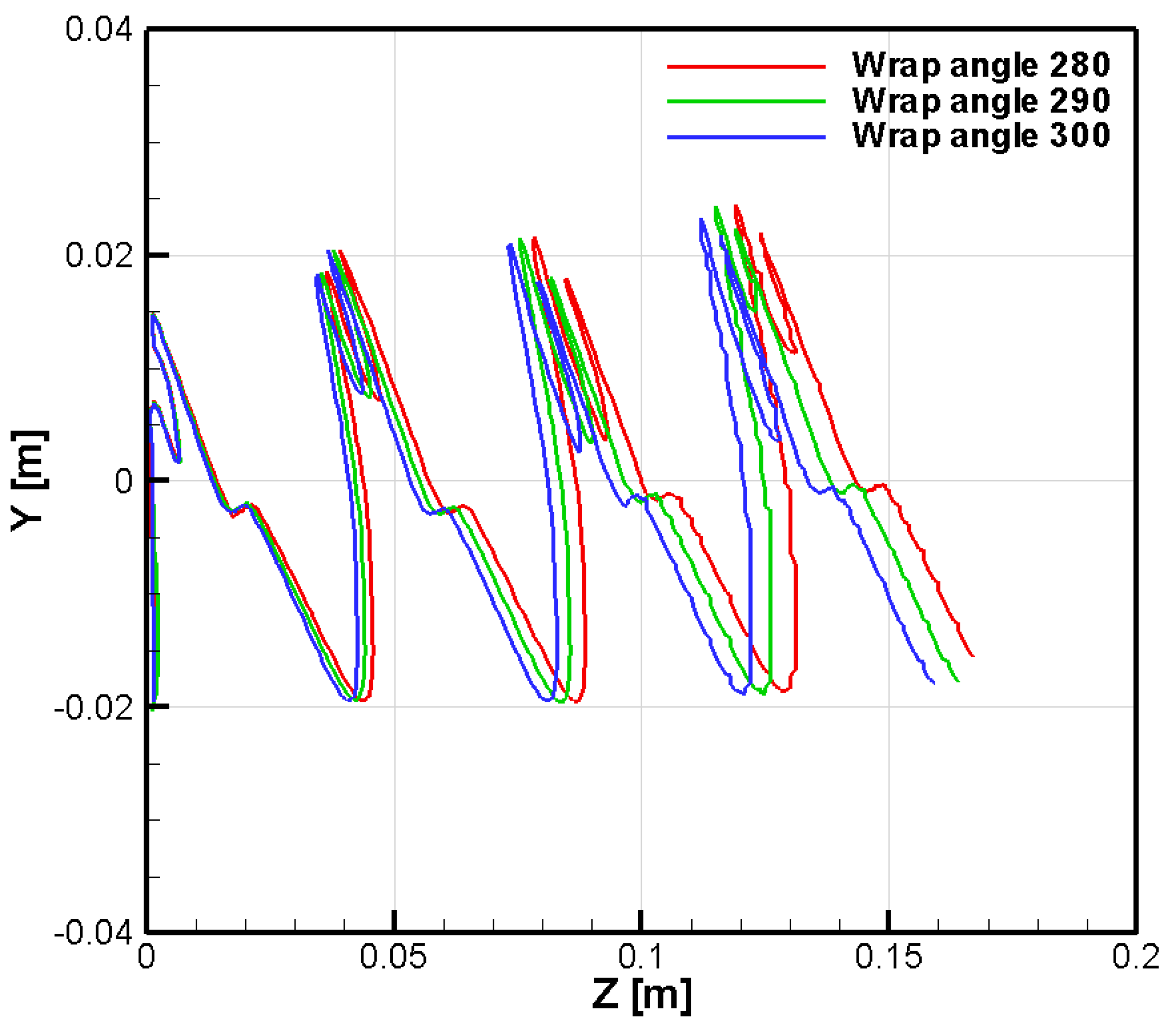
  • The wrap angle influenced the distribution of the sealing lines and altered the leakage flow, which affected the delivery rate and volumetric efficiency by up to 2%.
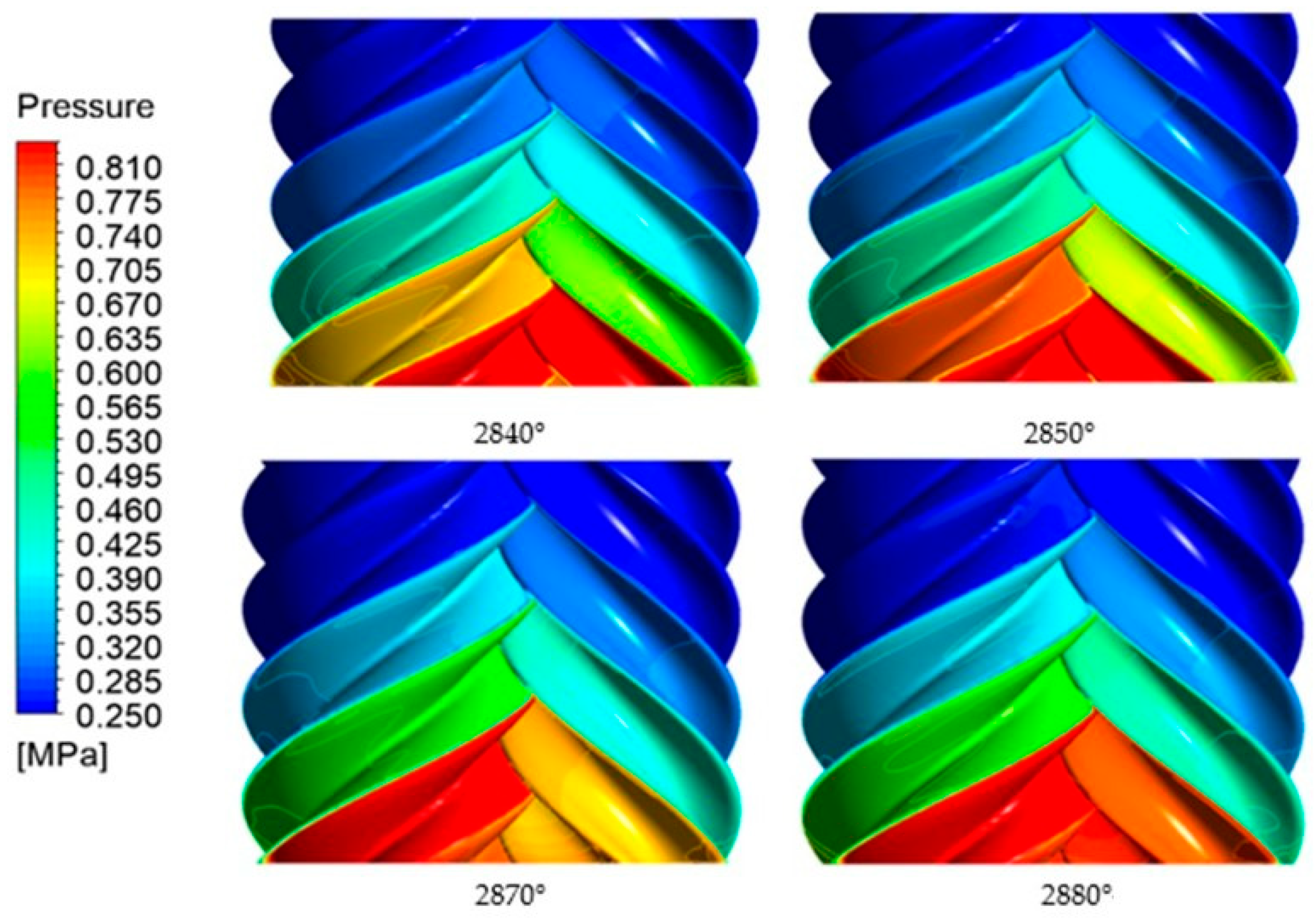
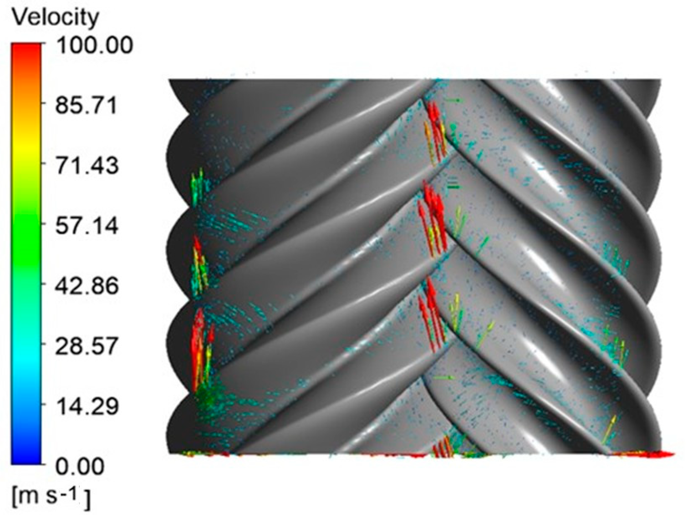
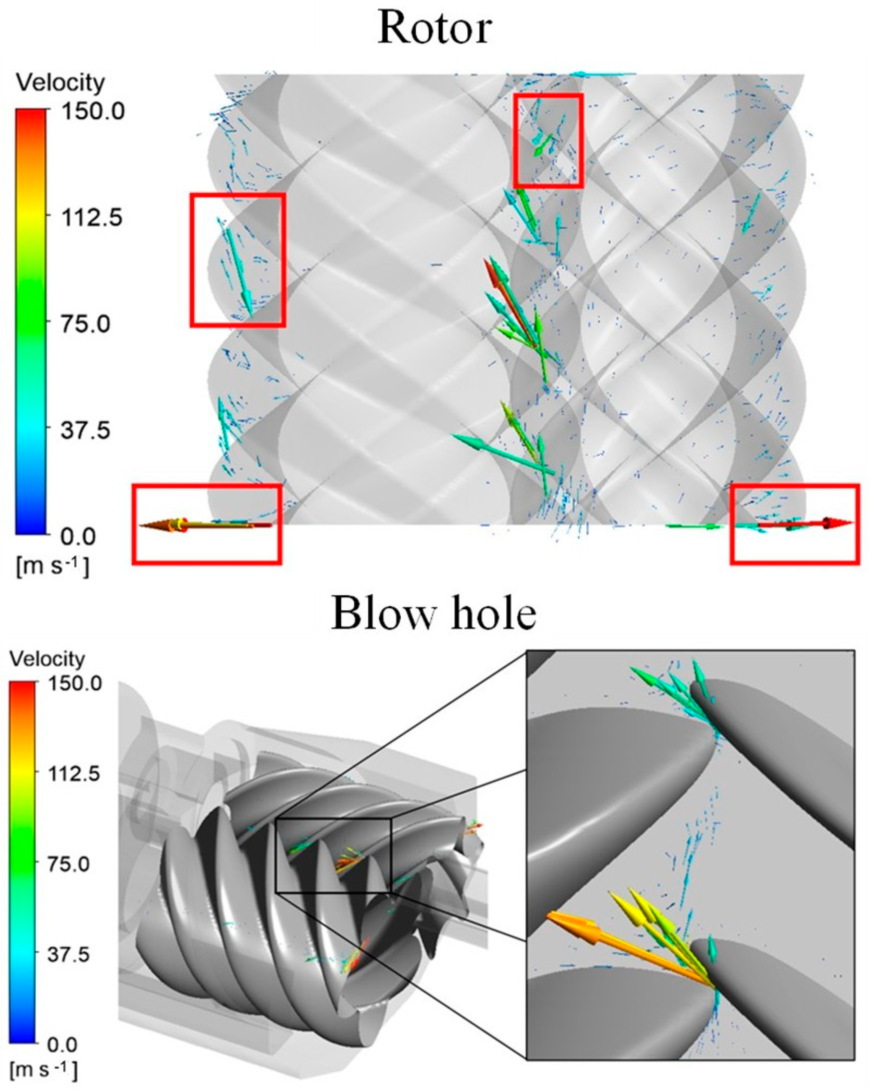
  • The leakage flow could be determined from the predicted flow distribution, and the highest velocity was above 100 m·s−1 during the compression process as a result of the small gap clearance.
  • The isentropic efficiency was not sensitive to the change in the wrap angle, and the difference was within 1%.
  • An increase in the pressure ratio led to a decrease in the mass flow rate and volumetric efficiency because of the higher leakage flow rate. However, its influence on the isentropic efficiency was also unnoticeable.
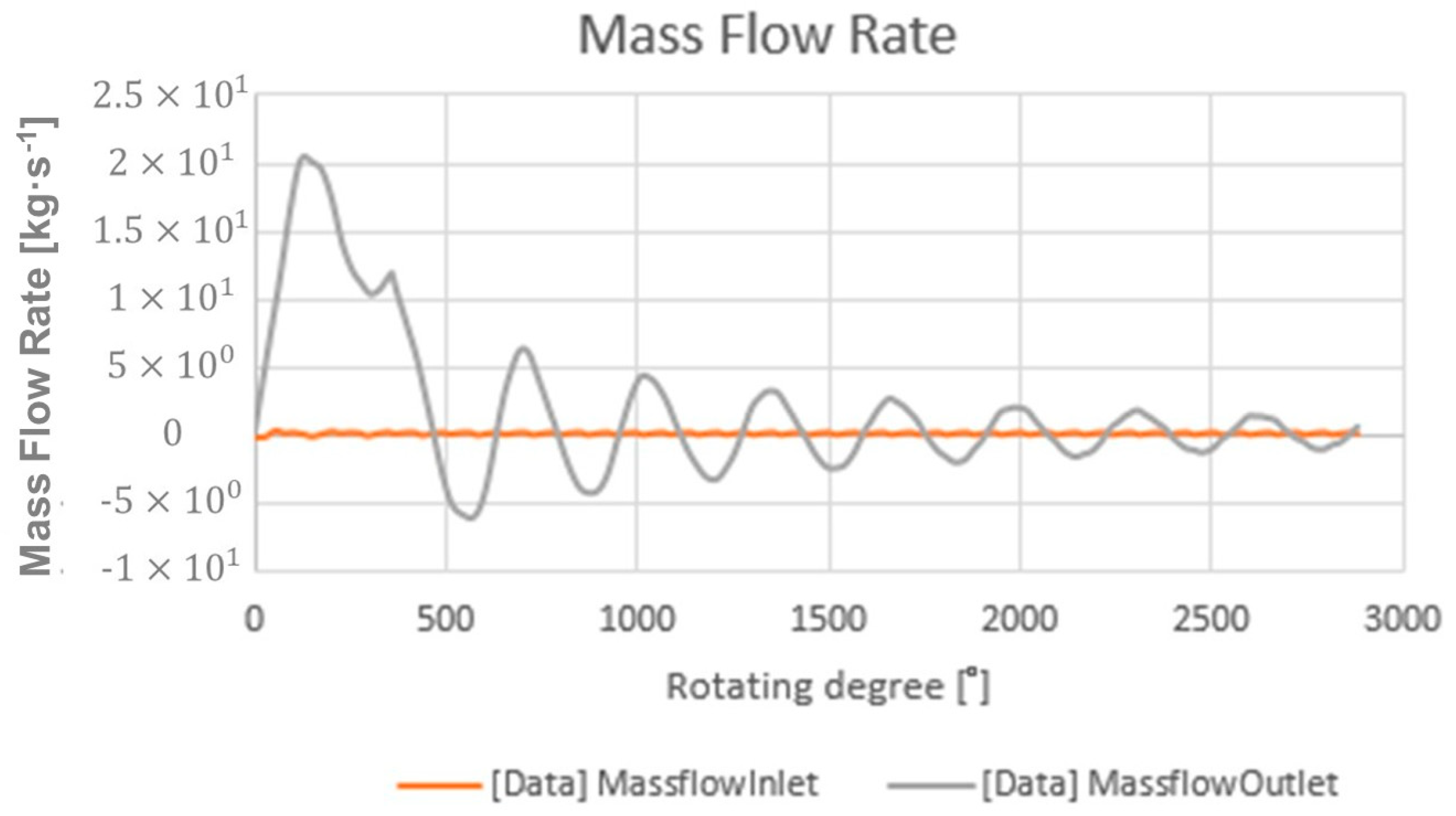
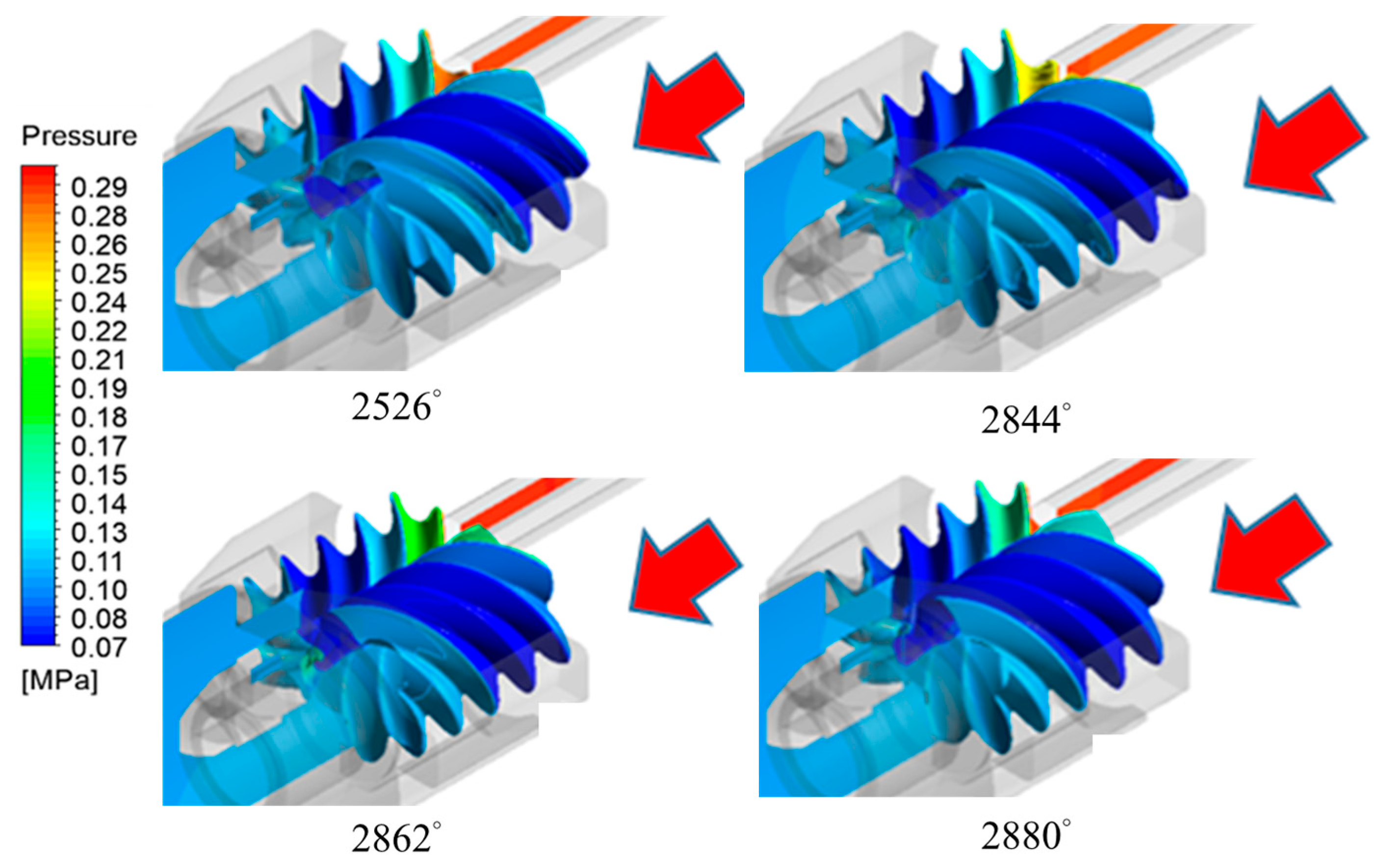
  • This screw expander was operated in underexpanded conditions, and the pressure contours demonstrated a minimum pressure level below the outlet pressure. Higher volumetric and isentropic efficiencies could be achieved if the expander was operated at a ratio that was close to the built-in expansion ratio.

Author Contributions

Conceptualization, C.-C.T., W.-K.L., K.-Y.L., S.Y. and Y.-H.L.; methodology, C.-C.T. and W.-K.L.; software, C.-C.T. and W.-K.L.; validation, C.-C.T. and W.-K.L.; investigation, C.-C.T., W.-K.L. and K.-Y.L.; data curation, C.-C.T. and W.-K.L.; writing—original draft preparation, C.-C.T., S.Y. and Y.-H.L.; writing—review and editing, C.-C.T., S.Y. and Y.-H.L.; supervision, S.Y. and Y.-H.L.; funding acquisition, Y.-H.L. All authors have read and agreed to the published version of the manuscript.

Funding

Funding was provided by the Energy R&D Foundation, Bureau of Energy, Ministry of Economic Affairs, Taiwan, under the grant number 110-E0202.

Conflicts of Interest

The authors declare no conflict of interest.

Nomenclature

C p Specific heat capacity
KThermal conductivity
PPressure
RGas constant
S T Internal heat source and the viscous dissipation term
TTemperature
u, v, wVelocity
μViscosity
ρDensity
τComponent of the viscous stress

References

  1. Stošić, N.; Hanjalić, K. Contribution towards modelling of two-stage reciprocating compressors. Int. J. Mech. Sci. 1977, 19, 439–445. [Google Scholar] [CrossRef]
  2. Stošic, N.; Milutinović, L.; Hanjalić, K.; Kovačević, A. Investigation of the influence of oil injection upon the screw compressor working process. Int. J. Refrig. 1992, 15, 206–220. [Google Scholar] [CrossRef]
  3. Stošić, N.; Smith, I.K.; Kovačević, A.; Aldis, C.A. The design of a twin-screw compressor based on a new rotor profile. J. Eng. Des. 1997, 8, 389–399. [Google Scholar] [CrossRef]
  4. You, C.; Tang, Y.; Fleming, J.S. Optimum rotor geometrical parameters in refrigeration helical twin screw compressors. In Proceedings of the International Compressor Engineering Conference, West Lafayette, IN, USA, 23–26 July 1996; p. 1074. [Google Scholar]
  5. Fleming, J.S.; Tang, Y.; Cook, G. The twin helical screw compressor Part 1: Development, applications and competitive position. Proc. Inst. Mech. Eng. Part C J. Mech. Eng. Sci. 1998, 212, 355–367. [Google Scholar] [CrossRef]
  6. Lee, W.S.; Ma, R.H.; Chen, S.L.; Wu, W.F.; Hsia, H.W. Numerical simulation and performance analysis of twin screws air compressors. Int. J. Rotating Mach. 2001, 7, 132087. [Google Scholar] [CrossRef]
  7. Rane, S.; Kovacevic, A.; Stosic, N.; Kethidi, M. Deforming grid generation and CFD analysis of variable geometry screw compressors. Comput. Fluids 2014, 99, 124–141. [Google Scholar] [CrossRef]
  8. Utri, M.; Brümmer, A. Improvement of the efficiency of twin-screw refrigeration compressors by means of dual lead rotors. In Proceedings of the International Compressor Engineering Conference, West Lafayette, IN, USA, 11–14 July 2016; p. 2474. [Google Scholar]
  9. Kovačević, A.; Stošić, N.; Smith, I.K. Grid aspects of screw compressor flow calculations. In Proceedings of the 2000 International Mechanical Engineering Congress & Exposition, Orlando, FL, USA, 5–10 November 2000. [Google Scholar]
  10. Kovacevic, A.; Stosic, N.; Smith, I.K. Screw Compressors: Three Dimensional Computational Fluid Dynamics and Solid Fluid Interaction; Springer Science & Business Media: Berlin/Heidelberg, Germany, 2007. [Google Scholar]
  11. Pascu, M.; Kovacevic, A.; Udo, N. Performance optimization of Screw Compressors based on numerical investigation of the flow behaviour in the discharge chamber. In Proceedings of the International Compressor Conference, West Lafayette, IN, USA, 16–19 July 2012; p. 2051. [Google Scholar]
  12. Kovacevic, A.; Stosic, N. CFD analysis of oil flooded twin screw compressors. In Proceedings of the International Compressor Engineering Conference, West Lafayette, IN, USA, 11–14 July 2016; p. 2392. [Google Scholar]
  13. Wu, H.; Lin, K.; Huang, H.; Xiong, B.; Zhang, B.; Xing, Z. Research on effects of vapor injection on twin-screw compressor performance. Int. J. Refrig. 2020, 118, 483–490. [Google Scholar] [CrossRef]
  14. Wu, X.; Xing, Z.; He, Z.; Wang, X.; Chen, W. Effects of lubricating oil on the performance of a semi-hermetic twin screw refrigeration compressor. Appl. Therm. Eng. 2017, 112, 340–351. [Google Scholar] [CrossRef]
  15. Wu, H.; Huang, H.; Zhang, B.; Xiong, B.; Lin, K. CFD Simulation and Experimental Study of Working Process of Screw Refrigeration Compressor with R134a. Energies 2019, 12, 2054. [Google Scholar] [CrossRef]
  16. Wang, W.; Wu, Y.T.; Ma, C.F.; Liu, L.D.; Yu, J. Preliminary experimental study of single screw expander prototype. Appl. Therm. Eng. 2011, 31, 3684–3688. [Google Scholar] [CrossRef]
  17. Zhang, Y.Q.; Wu, Y.T.; Xia, G.D.; Ma, C.F.; Ji, W.N.; Liu, S.W.; Yang, K.; Yang, F.B. Development and experimental study on organic Rankine cycle system with single-screw expander for waste heat recovery from exhaust of diesel engine. Energy 2014, 77, 499–508. [Google Scholar] [CrossRef]
  18. Papes, I.; Degroote, J.; Vierendeels, J. New insights in twin screw expander performance for small scale ORC systems from 3D CFD analysis. Appl. Therm. Eng. 2015, 91, 535–546. [Google Scholar] [CrossRef]
  19. Andres, R.; Hesse, J.; Babic, H.; Salecker, U.; Spille-kohoff, A.; Nikolov, A.; Bruemmer, A. CFD Simulation of a twin screw expander including leakage flows. In Proceedings of the International Compressor Engineering Conference, West Lafayette, IN, USA, 11–14 July 2016; p. 2497. [Google Scholar]
  20. Rane, S.; Kovačević, A.; Stošić, N.; Smith, I. Analysis of real gas equation of state for CFD modelling of twin screw expanders with R245fa, R290, R1336mzz (Z) and R1233zd (E). Int. J. Refrig. 2021, 121, 313–326. [Google Scholar] [CrossRef]
  21. Ansys, C.F.X. 10.0 User’s Manual; ANSYS Inc.: Canonsburg, PA, USA, 2013. [Google Scholar]
  22. Yang, S.; Ouyang, H.; Wu, Y.; Wang, L.; Mei, L.; Wang, H. CFD simulation for the internal pressure characteristics of an oil-injected twin-screw refrigeration compressor. Int. J. Refrig. 2021, 126, 143–154. [Google Scholar] [CrossRef]
  23. Rane, S.; Kovacevic, A.; Stosic, N.; Kethidi, M. Grid deformation strategies for CFD analysis of screw compressors. Int. J. Refrig. 2013, 36, 1883–1893. [Google Scholar] [CrossRef]
  24. Rane, S.; Kovacevic, A.; Stosic, N.; Kethidi, M. CFD grid generation and analysis of screw compressor with variable geometry rotors. In Proceedings of the Institution of Mechanical Engineers-8th International Conference on Compressors and Their Systems, London, UK, 9–10 September 2013; pp. 601–612. [Google Scholar]
  25. Kovacevic, A.; Rane, S.; Stosic, N. Computational fluid dynamics in rotary positive displacement screw machines. In Proceedings of the 16th International Symposium on Transport Phenomena and Dynamics of Rotating Machinery, Honolulu, JI, USA, 10–15 April 2016. [Google Scholar]
  26. Papes, I.; Degroote, J.; Vierendeels, J. 3D CFD analysis of a twin screw expander for small scale ORC systems. In Proceedings of the 11th World Congress on Computational Mechanics, Barcelona, Spain, 20–25 July 2014; pp. 7207–7217. [Google Scholar]
  27. Stosic, N. On heat transfer in screw compressors. Int. J. Heat Fluid Flow 2015, 51, 285–297. [Google Scholar] [CrossRef]
Figure 1. The geometry of the screw compressor and the fluid domain.
Energies 16 03599 g001
Figure 2. Wrap angle of male rotor.
Energies 16 03599 g002
Figure 3. Mesh of fluid domain and rotor screw.
Energies 16 03599 g003
Figure 4. Mesh independence verification of mass flow rate and power.
Energies 16 03599 g004
Figure 5. CFD results vs. rotation angle of male rotor for mass flow rate and power input.
Energies 16 03599 g005
Figure 6. Pressure contours on the rotors at different angles.
Energies 16 03599 g006
Figure 7. Sealing line on rotor surfaces of male rotor and female rotor.
Energies 16 03599 g007
Figure 8. Comparison of sealing line length.
Energies 16 03599 g008
Figure 9. The leakage flows at the rotors.
Energies 16 03599 g009aEnergies 16 03599 g009b
Figure 10. Temperature contours in male and female rotors.
Energies 16 03599 g010
Figure 11. Comparison of mass flow rates at different pressure ratios at inlet and outlet.
Energies 16 03599 g011
Figure 12. The mass flow rate at inlet and outlet.
Energies 16 03599 g012
Figure 13. The pressure distribution at different angles (Red arrow: the inlet flow direction).
Energies 16 03599 g013
Figure 14. The leakage flow at rotors and blow hole.
Energies 16 03599 g014
Table 1. Rotor geometry.
ParametersValue
Lobe combination5/6
Rotor length (mm)167
Inlet angle (°)280.52
Outlet angle (°)60.48
Male rotor head diameter (mm)138.54
Female rotor head diameter (mm)109.86
Center distance (mm)98
Wrap angle (male rotor) (°)280, 290, 300
Table 2. Boundary conditions.
ParametersValue
Compressor (R134a)Wrap angle (degree)280, 290, 300
Inlet pressure (bar)2.55
Inlet temperature (K)288.47
Discharge pressure (bar)8.05, 10.24
Discharge temperature (K)328.98, 337.45
Rotational speed (rpm)3600
Expander (R134a)Inlet pressure (bar)3
Inlet temperature (K)350.15
Discharge pressure (bar)1
Discharge temperature (K)311.03
Rotational speed (rpm)3600
Table 3. Comparison of different wrap angles.
Wrap AngleFlow Rate (kg·s−1)Power (kW)Volumetric
Efficiency (%)
Isentropic
Efficiency (%)
280°0.74235.674.554.6
290°0.73235.273.8554.5
300°0.71934.8372.954.1
Disclaimer/Publisher’s Note: The statements, opinions and data contained in all publications are solely those of the individual author(s) and contributor(s) and not of MDPI and/or the editor(s). MDPI and/or the editor(s) disclaim responsibility for any injury to people or property resulting from any ideas, methods, instructions or products referred to in the content.

