Abstract
In this paper, the oscillation phenomena of the scalar magnetic potential of iron pieces of spoke permanent magnet (PM) machines are analyzed and the effects of the oscillation on the air gap flux and back electro-motive force (EMF) are deeply investigated, especially for flux modulation machines such as vernier and flux switching PM (FSPM) machines. To these ends, the formula of the scalar magnetic potential is derived for a generalized spoke PM structure. It reveals that the oscillation phenomena depend on the slot/pole combination, consequently resulting in different behavior according to the machine types such as vernier and FSPM machines. Next, each core’s potential given as a discrete function is developed into a continuous function of an air gap magneto-motive force (MMF) rotating and oscillating through Fourier series expansion. Making use of the developed MMF and the specific permeance of air gap, the equations of air gap flux density and back EMF are derived, which enable accurately estimating the suppression of the modulation flux and the back EMF due to the potential oscillation for different types of spoke PM machines. For validation, various magnetic characteristics are quantitatively examined for different type of spoke PM structures, including PM vernier and FSPM machines, and verified by comparing with FEM simulation results.
1. Introduction
Flux modulation machines (FMMs), due to their higher torque density, are receiving considerable research attention [1,2,3,4,5,6]. FMMs, due to their higher torque densities, are promising for direct drive applications such as wind turbines [5,7]. FMMs operates on the principle of the magnetic gearing effect, where the gear ratio defines the degree of the magnetic gearing effect [7].
The FMM family, with various topologies, can be classified with PM position and the general surface PM topology; the consequent pole is famous for its magnet saving capability [8], while the spoke PM structure has the advantage of the flux focusing effect, due to which spoke-type topology is often discussed for conventional PM machines [9,10]. The representative FMM spoke types are the spoke PM vernier machine [10] and the flux switching PM (FSPM) machine [11,12]. However, FSPM has the PMs between the stator core pieces in the form of spoke-arrays. In contrast, the PMV machines has the PM on the rotor side.
The slot harmonics of air gap permeance which cause the magnetic gearing effect significantly depend on the effective air gap length [13]. In this respect, a spoke PM vernier machine with an inherently short air gap was tried, and for the first time a phenomenon named as magnetic potential oscillation was found, due to which the modulation flux is rather greatly reduced. This phenomenon of magnetic potential oscillation is actually due to the separation of rotor core pieces, and the previous authors have explained the leading cause with the harmonic permeance of air gaps that vary with rotor position. Thus, a dual air gap spoke PM structure was recommended to overcome the problem of harmonic permeance variation and, consequently, the magnetic potential oscillation [14]. Later, the phenomenon of magnetic potential oscillation was re-experienced in [15], and a new name, ‘flux-barrier effect,’ was given to the same phenomenon based on numerical analysis. It was shown that the modulation flux is suppressed by the additional reluctance introduced by an oppositely polarized magnet which acts as a flux barrier in spoke-type FMMs, especially with higher gear ratios. However, for FSPM machines, despite having a spoke structure the same as a vernier machine, it was confirmed through numerical analysis that the reduction of modulation effects severely occurs exceptionally only in a specific gear ratio [15,16]. Unfortunately, in the previous works so far, due to lack of a well-defined analytical approach, it was not possible to analytically explain the development of potential oscillation and, thus, the problem was analyzed based only on the numerical analysis, which greatly limits deep insights into the problem. Moreover, due to the paradoxical nature of magnetic potential oscillation, it was not unified for the class of spoke PM machines. In view of all of these concerns, a generalized analytical model is necessary.
This study presents a generic analytical approach to the phenomena of potential oscillations by improving previous work that was insufficient for predicting the phenomena precisely [14]. In particular, the derived analytical expressions are applicable to any spoke PM machine, although the focus of this study is on FMMs. To this end, first, a general spoke structure is considered and the equation of the magnetic potential of iron pieces is derived from an appropriate hypothesis. The derived equation reveals that the potential oscillation phenomena of iron pieces significantly depend on the slot pole combination. It indicates that the effects of a potential oscillation problem vary with the type of machines, as the criteria for slot-pole selection is different for machine topologies. Next, to obtain the air gap flux density and the back EMF expressions, the potentials of core pieces given as discrete function are developed into a continuous function through Fourier series expansion. The derived expressions are not only helpful to clearly understand the nature of potentials oscillation but also make it possible to quantitatively analyze its effects on the performance of any given spoke PM machine regardless of the slot pole combination. Finally, for validation, magnetic characteristics of various spoke PM prototypes are analyzed analytically and compared with the results obtained by FEM.
2. Characteristic Equations Considering Magnetic Potential Oscillation
2.1. Generalized Equivalent Circuit Model of a Spoke-Array PM Machine
Figure 1 shows three representative spoke-array PM machines, and each has a different operating principle, specific criteria for the selection of the slot-pole depending on winding configurations. In this study, to obtain a universal expression for potential of any spoke-arrayed core pieces, a generalized model is assumed consisting of an upper core with ZU slots and a lower core with ZL iron pieces and spoke-arrayed PMs, as shown in Figure 2a, where Ωk is the scalar magnetic potential, Φk is the air gap flux, Φm.k is the flux of PM and Φleak is leakage flux. Compared with three in Figure 1, the upper core of Figure 2a acts as the stators of conventional PM and vernier machines and as the rotor of FSPM machine.
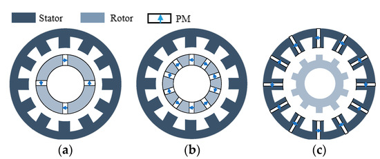
Figure 1.
Various PM motors with spoke structure. (a) Conventional, (b) Vernier, (c) Flux switching.
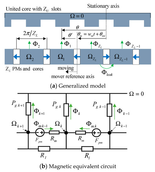
Figure 2.
Generalized model of PM motors with spoke structure.
The magnetic equivalent circuit of the model of Figure 2a is constructed as Figure 2b where is the lumped permeance of air gap connected with the kth core piece between PMs with MMF Fpm and the magnetic reluctance Rm, and the reluctance Rl is for the leakage. In particular, is calculated using the specific permeance as follows.
For ease, the center of the upper slot is set as stationary axis, as shown in Figure 2a. Assuming the lower moves, whose air gap position is θm, the upper and the lower sided permeance functions ΛU and ΛL are given respectively as
where λ in (1) and (2) are determined by air gap geometries [17]. The net air gap permeance is approximated as
where g is the air gap length, , . With the core stack length lstk, and the air gap radius rg, the kth lumped permeance of Figure 2b is obtained as (4) where θk is .
Letting as the angle in mover reference, as shown in Figure 2a, θk can be expressed as . Solving (4) with (1)~(3), one can get (5)
where , , , and . It should be noticed that oscillates with the mover position θm due to the 2nd term in (5).
2.2. Analytical Expressions of Scalar Magnetic Potential
From Figure 2b, the following relations for flux Φ, (6), and (7) can be obtained for the kth core piece.
where and . Substituting (7) into (6) yields the following.
If without PΔ in (5), is constant with respect to mover position and the core pieces have the same magnitude of magnetic scalar potentials but alternating signs. Then, the potential Ωk given as the form of (−1)k−1Ωav is easily solved from (8). However, with PΔ varies with mover position; causing Ωk also does, and it is tricky to directly achieve the analytical solution of Ωk using (8). Thus, in this study, a trial function is assumed to get the proper expression of Ωk.
Under the hypothesis that the harmonics of ZU and ZL/2 of produces the modulation harmonic of |ZU − ZL/2| in Ωk, the function (9) neglecting high order harmonics is tried, where ZL/2 is replaced with the PM pole pairs ZPM and (−1)k−1 is replaced with because of . The magnitudes Ωav and ΩΔ1 need to be determined to satisfy (8), and using (9), with consideration of the PM direction, Ωk−1 + Ωk+1 in (8) can be calculated as (10).
Solving (8) for Ωk using (10), one gets
where the coefficient in the second multiplication term,
To determine Ωav and ΩΔ1 by comparing (11) and (9), the 2nd factor of (11) is changed into Fourier series as
where and .
Substituting (13) into (11), one gets
Ωk of (14) contains additional higher harmonics neglected in (9), which confirms that Ωk of (9) is an approximate solution as assumed. Finally, from (14) and (9), Ωav and ΩΔ1 are given as
Now, the potential Ωk of (9) is apparently defined with (15) and (16), which indicates both the fixed potential value Ωav and the oscillation amplitude Ω∆1 are affected by γz because Kp of (12) is also dependent on γz. In particular, Kp must be much smaller than unity because Pav is much larger than PΔ in (12). Hence, it can be said that γz (ZU/ZL); that is, the combination of slots and PM poles has much larger effects on Ω∆1 than Ωav.
2.3. Air Gap Magneto-Motive Force
It is necessary to multiply the air gap MMF with specific air gap permeance in order to get the air gap flux density and the back EMF. The air gap MMF is the difference of the magnetic potentials of the upper and the lower cores, and the potential of the upper core is zero (see Figure 2), so the obtained potential of (9) can be directly used for the air gap MMF Fg given as
which is a piecewise function expressed in mover reference frame using the angular position . However, Fg of (17) is in a very inconvenient form to multiply with the permeance of (3). Therefore, it is helpful to change it into a continuous series function, especially in stationary reference frame as (3). Let the 1st and the 2nd term of (17) be and , respectively. Since is a square wave with the period of 2π/(ZL/2) in mover reference frame, it can be easily changed into Fourier series form and into the stationary reference frame using the relation as follows
Similarly, using the Fourier series , can be represented as (19), the detailed derivation procedure of , is in Appendix A.
Now, letting the modulation pole pairs as
using (18) and (19), the air gap MMF Fg is finally obtained as
where , , and .
The 1st term of (21) is the general MMF wave of every PM machine with (=ZL/2) pole pairs including the surface PM vernier. However, the 2nd and the 3rd term are unique waves that appeared in a spoke-array PM structured machine due to the oscillation of the scalar magnetic potential of each core. Thus, there is inevitable influences on the air gap flux density and back EMF predominantly due to the MMF waves.
2.4. Air Gap Flux Density and Back EMF
Multiplying the air gap permeance of (3) and the MMF of (21) the air gap flux density is approximated as
The flux density Bg of (22) has been derived with the lower body as a mover in Figure 2a, so it can be used for a vernier and a conventional machine since their windings are installed in the upper body. However, the frequency of the back EMF in the stator winding by the flux of (22) is determined by the coefficient of. Since vernier and conventional PM machines use the fundamental PM flux in common, the coefficient of should be the same as . In addition, one in the 2nd term in (22) induces negligible voltage due to its low speed of . Consequently, the working flux for the conventional and vernier machines are as follows.
where the 1st term is commonly called the main flux and the 2nd is the modulation flux. Their back EMF is the time derivative of the flux linkage due to (23) so it has a relation given as
where Kc is the coefficient related to the number of turn (Nph), machine geometry that is radius of airgap (rg) and stack length (lstk), and rotational speed (ωm). is the gear ratio given as for the conventional and vernier PM machines. The coefficients and are the winding factors for two fluxes in (24) and depend on the coil span of winding, so the span needs to be properly chosen. In case of 3-phase concentrated windings, the winding factor for each harmonic can be obtained by where is the mechanical angular span of each coil.
On the other hand, in the case of an FSPM, whose PMs and windings are installed in a stator, (22) should be modified considering the motion of the upper body instead of the lower, which is achieved by changing θ with θ + θm given as,
It is evident that in the 1st term of (25), the main flux remains static, and thus only the modulation fluxes are able to produce the back EMF. In particular, it should be noted that the frequencies of back EMF due to the modulation fluxes are all the same, ZU. As results the working flux and the back EMF for the FSPM are given by
where is the gear ratio given as . Comparing the back EMF expressions of (24) and (27), the FSPM machine does not utilize the main flux but does various harmonic modulation fluxes to get the back EMF while the conventional and the vernier machines make use of just the fundamental fluxes of the main and the modulation fluxes.
2.5. Suppression Characteristics of Modulation Flux Due to Magnetic Potential’s Oscillation
From (22) to (27), it is also evident that the term in the parenthesis, arisen due to the potentials oscillation in spoke array PM structure, suppresses the modulation flux and, thus, results in the reduction of back EMF. In particular, this unique phenomenon occurs differently for the types of the machines because is dependent on γz (slot-pole combination). To quantitatively evaluate the suppression of the modulation flux when the coefficient is defined as
and then the back EMF due to the modulation flux in (24) and (27) can be given as (29). Thus, indicates the reduction rate of the modulation flux with the nth harmonic order
In order to quantitatively calculate with variation of the ratio γz, the realistic geometries of spoke PM structures are assumed for which the PM thickness wm is 1/5 of the pole arc length and the PM height hm is the pole arc length. Under these assumptions the PM reluctance, Rm becomes . In addition, assuming that the ratio rg/g is 100, one gets and where kc is Carter’s coefficient considering both the upper and the lower slots, and then Kp of (12) becomes
Consequently, the reduction rate is given as (31), which reveals the reduction rate of modulation depends on ZL as well as γz, that is, ZU/ZL. For 0 ≤ γz ≤ 2.5 and various values of ZL, the values of are calculated and shown in Figure 3 in which the gear ratios for a vernier machine and | for FSPM are also depicted.
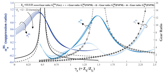
Figure 3.
Suppression ratio and gear ratio of harmonic modulation fluxes with γz (=ZU/ZL).
Figure 3 shows that when γz gets closer to 0.5 n where n is an odd integer, the ratio for nth harmonic approaches infinity but the reduction rate also gets unity (meaning most of the nth modulation flux are lost). Conversely, when γz is an integer, all are zero (no reduction for any modulation flux), but most gear ratios are quite small. To be exact, as the integer γz increases, the ratio gradually increases although its corresponding harmonic MMF in (26) reduces.
It can be concluded that in the case of a spoke-array PM FMMs, the gear ratio and the reduction rate of the nth modulation flux tend to be proportional to each other. Therefore, it is difficult to obtain high magnetic gear effects due to the potential oscillation phenomena, and this phenomenon is more severe for the 1st harmonic (n = 1).
3. Potentials Oscillation Behavior in Various Spoke PM Machines
The three spoke PM machines in Figure 1 have unique operation principles and specific criteria for selection of slot-pole combination. In this section, using the derived Equations (22)–(27), the reduction coefficient and the results of Figure 3, the nature of potential oscillations for each spoke PM machine is discussed in which the machine’s own criteria of slot-pole combination is separately considered for the integral slot (IS) and fractional slot concentrated (FSC) windings.
3.1. Conventional Spoke PM Machine
Conventional PM machines were classically devised to utilize the main flux only, and the modulation flux has a negligible contribution [18], due to the small values of in (24) regardless the presence of the potential oscillation. Thus, potential oscillations are briefly discussed.
In case of the IS windings, the slot-pole combination is as follows; the PM Pole pairs, (=ZL/2) of (23) is same to the winding pole pairs. To obtain the pole pairs, the stator slots, ZU in Figure 2 should 6 pwm in 3-phase windings where m is a positive integer. Hence, must be an integer, and the modulation fluxes have no suppression as shown in Figure 3.
For FSC winding, available slot-pole combinations are numerous and the concept of winding pole pair becomes unclear, making it difficult to define the combination criteria in a simple manner. Thus, as examples the most popular slots/PMs ratio of 3/4 and 3/2 are examined. From Figure 3, when is 3/4, is about 2 and is about 0.3, resulting in trivial contribution to the back EMF. Also, for = 3/2, is 0.5 negligibly small. In conclusion, the conventional machine is free from potential oscillation issues, but the magnetic gear effect is also small enough to be ignored.
3.2. Spoke PM Vernier Machine
The windings of FMMs are configured to use the modulation flux in (23). It leads to the condition for IS winding, under which . The condition can be rewritten as (32). Replacing the stator slots ZU in (32) with 6 pwm, the PM poles ZL can be obtained as 2 pw (6 m − 1). The ratio becomes 3 m/(6 m − 1) and the ranges of with a positive integer m can be given by (33)
According to Figure 3, the gear ratio, is 5 at = 0.6 (for m = 1) and significantly increases as m increases. Therefore, it is beneficial to use larger m for surface PM vernier machines. For the spoke PM structure, however, the corresponding reduction ratio is also greater than about 0.75, so the back EMF achieved from the modulation flux is severely reduced, as discussed in [15].
Additionally, from (24), it is worth noting that both main and modulation flux simultaneously contribute to the back EMF. The PM pole pairs ZL/2 is pw(6 m − 1), an odd multiple of the winding pole pairs , yielding of (24) close to 1. As the permeance is quite large compared to the harmonic one , the PM vernier machine additionally receives back EMF from the main flux, this is why the back EMF of a surface PM vernier machine is superior to the conventional machine’s [19].
The FSC winding can be configured to use the 1st harmonic modulation flux. In the conventional fluxes discussed previously, the slots-PMs ratio of 3/2 (or 3/4) implies that 2 (or 4) pole length of the main flux is divided by 3 stator slots. Similarly, in the vernier machine with ZU stator slots and ZL rotor PMs, the stator slots in the 2 (or 4) pole length of the modulation flux with pole-pairs is divided into thirds. The condition for these is given as in which α is 3/4 or 3/2 and replacing with ZU − 0.5 ZL, one gets
It is interesting that for m = 1, becomes 3/2 and 3/4 when α = 3/4 and 3/2, respectively, which are the same of the conventional PM machine. In other words, two vernier machines for m = 1 belong to the conventional PM machines. In addition, for m = 2 and α = 3/4, also becomes 3/4 of conventional machines. Thus, they have very small gear ratio less than 2 or useless infinity. For m ≥ 2 except 3 cases above, the range of is given as 0.5 < < 0.6 which are same to that for the IS windings (33) and, thus, the same phenomena happen to the machine.
3.3. Flux Switching PM Machine
Different from a PM vernier, an FSPM has both the excitation sources on the stator represented by the lower body of Figure 2a. Hence, ZU and ZL represent the number of rotor teeth and PM poles, respectively, in FSPM structure, and only the modulation fluxes are responsible for back EMF production as discussed. Recalling that the spoke PM vernier machine hardly uses the gear effects due to potential oscillations, it seems natural to guess the similar conclusion for FSPM with spoke PMs. But the existing literature on FSPMs have rarely mentioned the problems related with potentials oscillation. Thus, the investigations on potentials oscillation and its effects on the FSPM is worthwhile.
As shown in (26) and (27), the back EMF of FSPM is the sum of each back EMF caused by various harmonic modulated magnetic fluxes excluding the main flux. Therefore, in order to predict the back EMF, for each harmonic component it is necessary to consider the gear ratio, the reduction rate and the winding factor for a given winding. The relation (20) can be given as in which ZL is the number of stator slots of FSPM, so ZL varies depending on the winding configurations and the number of poles of the modulation flux.
First, in the case of an FSPM having integral (m) slot distributed winding with the winding pole pairs , the stator slots ZL is 6 pwm, so the rotor slots ZU becomes (3 m + 1)pw and finally the ratio γz (=ZU/ZL) is given as
In the range of (35) in Figure 3, is larger than 4, and for the modulation flux with pole pairs is close to 1. However, the corresponding is also quite large as 0.5 or more, reducing the gear effects. In addition, both and are less than 1 and their winding factors become also much smaller since is not the multiples of . Therefore, there is little contribution from the harmonic modulation fluxes regardless . Consequently, the IS winding is improper for FSPM even if it has a considerable gear ratio for .
Second, for the FSC winding, assuming that 2 or 4 poles of the 1st modulation flux wave are equally divided into 3 slots, one gets the relation and γz of ZU/ZL is calculated as 5/6 and 7/6 for the ratio of 3/2 and 3/4 respectively.
Examining the gear ratios and reduction ratios, when γz = 5/6, = 2.5, 1.25, 0.5 and = 0.15, −0.23, −0.15, and when γz = 7/6, = 3.5, 1.75, 0.87 and = −0.07, 0.4, 0.16. It indicates, for FSC windings, the gear ratios for various harmonic modulation fluxes are neither too large nor too small. In addition, some of the reduction ratios have negative values that increase the modulation fluxes. Considering the coil span for FSC windings, the winding factor for all harmonics is equally 0.87 as given by
Based on the above, every harmonic modulation flux contributes to back EMF production with almost no reduction, which is why most common FSPMs have FSC despite their non-significant gear ratio .
4. Validation with Case Studies
4.1. Analysis Models
For validation, four prototype models shown in Figure 4 are designed, the main design parameters are given in Table 1. For each prototype the PM dimensions are selected as per the predefined assumption.
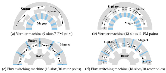
Figure 4.
Designed spoke PM machines for analysis.

Table 1.
Main Design Parameters of the Prototype Models.
The conventional spoke PM machine is not chosen for analysis as it has negligible contribution form the modulation flux, so the suppression of modulation flux is irrelevant. However, for spoke PM FMMs, where the modulation flux plays an important role, the modulation flux is expected to be suppressed very differently depending on the gear ratio. To prove this, for each spoke PM vernier machine and FSPM, two models with lower/higher gear ratio are selected, as shown in Figure 4, and their gear ratios, γz and the suppression ratios are given in Table 1 as well as depicted in Figure 5. It can be noticed that models with higher gear ratios have relatively higher.
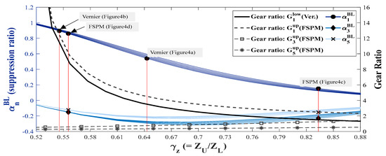
Figure 5.
Suppression ratio and gear ratio of harmonic modulation fluxes with γz (=ZU/ZL) of all analysis models (reproduced from Figure 3).
As far as the winding configuration is concerned, γz of spoke vernier is irrespective of the winding configuration. But for FSPM, γz and, hence, depend on the winding configuration and usually FSPM with higher gear ratios are feasible with IS winding. Thus, FSPM with lower and higher gear ratio are designed with FSC and IS windings.
4.2. Procedure for Verification with FEM
In order to demonstrate the suppression phenomena of the spoke FMMs, both the magnetic characteristics with/without considering the potential oscillations for each prototype are analytically obtained and are compared, including FEM results.
As discussed, the suppression of the modulation flux is fundamentally caused by the potentials oscillation of the iron core pieces and its effect in analytical expressions starts from the existence of Kp in (14) and (15). If Kp = 0, the oscillation magnitude Ω∆1 of (16) and in (21) are made to 0, and the effects of potentials oscillation are neglected on the air gap MMF and flux density. With/without Kp, for each model, the flux density and the back EMF is obtained and compared with the FEM results. The discussion clearly reveals the effect of potentials oscillation on suppression for each prototype.
4.2.1. Vernier Machine
The two spoke vernier prototypes of Figure 4a,b have of 7 and 11, of 2 and 1, and gear ratio of 3.5 and 11, respectively. For both the models, the air gap MMF of (21) has been obtained with/without the potentials oscillation (their waveform is depicted in Appendix B, Figure A1), and their harmonics are illustrated in Figure 6(,). There is a slight increase in when potential oscillations are considered due to non-zero Kp in (15). It should be noticed that the th oscillating MMF for both models expected to suppress the modulation flux is considerable, and that of Figure 4b with higher is larger.
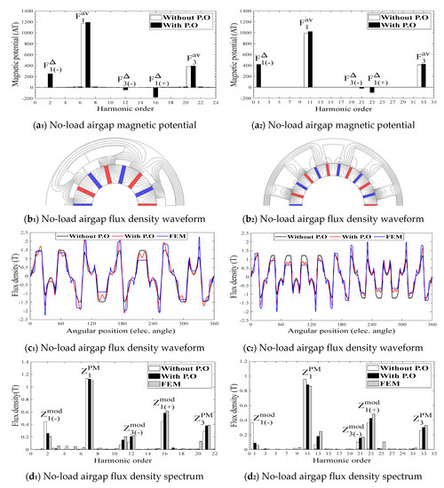
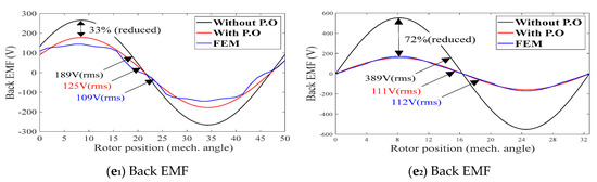
Figure 6.
Spoke PM veriner (Subscript 1 and 2 represents the model with 9–slots/7–PM pairs and model with 12–slots/11–PM pairs, respectively).
Then, for each machine the no-load flux lines are shown in Figure 6(b1,b2) and the air gap flux density waveforms obtained using the proposed expression (22) in both the manners are compared in Figure 6(,). Figure 6(,), the spectrum of air gap flux density harmonics, which clearly shows the suppression of working modulation flux. From the results of Figure 5, the magnitude of the th modulation flux harmonic is expected to be suppressed about 58% and 89% for of 3.5, and 11, respectively, from those without considering the potentials oscillation. The FEM results in Figure 6(,) validate the accuracy of the predicted suppression of modulation flux harmonic of order, in both models. Furthermore, the modulation fluxes with the harmonic order of such as the 16th in Figure 6() and the 24th in Figure 6(), though having little contribution to the back-EMF, are oppositely increased by the potentials oscillation as predicted in (22), which proves the accuracy of the proposed equations.
Finally, Figure 6(,) compares the no-load back EMF waveforms from FEM and the analytical calculation using (24), where the analytically obtained ones have no distortion since no time harmonics are included in the calculations. Additionally, the rms values of the fundamental component of back EMF are expressed in Figure 6(,). It can be seen that the calculated back EMFs with potential oscillation is much closer to the FEM results. Indeed, it is because the modulation flux harmonics much reduced and is more serious as the gear ratio is larger as anticipated from the air gap flux density results.
4.2.2. Flux Switching Machine
To verify the effects of potential oscillations on the FSPM machine, two FSPM models of Figure 4c,d are investigated. The one has 12–slots/10–rotor poles (γz = 0.833) with FSC winding, commonly used model in literature [20], with a quite low gear ratio of = 2.5.
Unlike vernier machines, various th modulation fluxes contribute to the back EMF. In this regard, = 1.25 for the th is not negligible. The other has IS windings, 18-slots/10-rotor poles (γz = 0.55), gear ratio = 10 much larger and = 0.58 smaller than the prior’s. As before, the air gap MMF of both models are calculated analytically (their waveform is shown in Appendix B), and their Fourier representation is illustrated in Figure 7(,) which clearly show that the oscillating MMF of the model with = 10 is much larger than that of one with = 2.5. Also, the th MMF of both models are negligible, so it is expected to not to suppress the modulation flux with = 1.25 and 0.58, respectively.
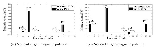
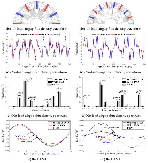
Figure 7.
FSPM (Subscript 1 and 2 represents the model with 12–slots/10–rotor poles model with 18–slots/10–rotor poles, respectively).
Next, the no-load flux lines are shown in Figure 7(,), and then the air-gap flux density waveforms are compared with those obtained using (25) in Figure 7(,). The harmonic spectra of the air gap flux density waveforms are shown in Figure 7(,). According to the results for γz = 0.833 and 0.55 in Figure 5, the th modulation flux harmonics is suppressed about 15% and 84%, respectively, due to the potential oscillations. Meanwhile, the th modulation flux harmonic is predicted to slightly increase for both. The FEM results compared in Figure 7d evidently validate those predictions. It is also notable the th modulation fluxes, though their negligible contribution to the back EMF, increase due to the MMF , as can be expected from (25). These results endorse the accuracy of the proposed analytical equations for potential oscillations.
Finally, Figure 7(,) compares the no-load back EMF waveforms from FEM and the analytical calculation using (26). The rms value of the fundamental component of back EMF is also stated in Figure 7(,). It is seen that the machine with 12-slots/10 rotor poles (= 2.5, 1.25) has insignificant difference in the analytically calculated back EMF values, because the modulation fluxes with moderate gear ratios are little suppressed by the potential oscillations and they produce a back EMF in cooperations.
However, the one with 18-slots/10-rotor poles (= 10, 0.55) has a huge difference between the back EMF values, which is evidently due to considerable reduction of the th modulation flux and negligible gear ratio of . It is evident that the analytically calculated back EMFs with consideration of oscillations are in very good accordance with the FEM results which validates the proposed method. It is interesting to note that both the FSPM machines with very different finally have almost same back EMF. In this case, of course, the FSC winding would be preferred over the IS winding with a much longer end turn length.
5. Conclusions
This study presents an accurate analytical modeling of the scalar magnetic potential oscillation phenomena that uniquely occur in spoke PM flux modulation machines and cause the suppression of modulation fluxes. An air gap MMF equation clearly explaining the phenomena is newly proposed and is further utilized to derive the accurate expression for the air gap flux density and back EMF for each spoke PM machine. By using the derived expressions for each spoke PM machine type, the effects of the potential oscillations on the flux modulation characteristics are quantitatively investigated for various slot-pole combinations. The high accuracy of the calculation results are confirmed by comparing them with the FEM results. After comprehensively investigating the potential magnetic oscillations for each spoke PM machine type, the following conclusions were obtained:
First, in the case of conventional spoke PM machines, the modulation flux has negligible contribution in the back EMF production, thus, the phenomenon of potential oscillations seems irrelevant. The proposed equations clearly show that conventional spoke PM machine with IS winding has zero suppression, however, with FSC winding there exists a certain suppression ratio, but the associated gear ratio is too small to have any significant impact on machine performance. Therefore, it is deduced that the potential oscillations have no effect on the performance of conventional spoke PM machine.
Secondly, the spoke PM vernier machine has considerable suppression of modulation flux due to the potential oscillations. Furthermore, it is revealed that the degree of suppression is interlinked with the machine’s slot-pole combination and the resulting gear ratio; however, it is independent with the winding configuration. For instance, for a gear ratio of 5 the suppression ratio is 65% and for a gear ratio of 11 it is as high as 89%, which clearly shows that the suppression increases as the gear ratio gets higher.
Finally, for the flux-switching PM (FSPM) machine, the case is more appealing because there are multiple modulation fluxes with various gear ratios and winding factors, and for each modulation flux there exists a certain suppression ratio. It is revealed that FSPM machine with IS winding, despite having a higher gear ratio, has poor back EMF characteristics, mainly due to a higher suppression ratio of 50% or higher. In contrast, unlike the previous case, FSPM machines with FSC winding have same high winding factor for every working harmonic, in addition, the suppression ratios are relatively low and, more interestingly, it is found that some modulation fluxes have even positive impact due to the potential oscillation phenomenon. Therefore, it is clear that FSPM with FSC winding, despite their lower gear ratios, are more desirable than that of the FSPM with IS winding.
Author Contributions
Conceptualization, L.U.R., A.R. and B.K.; methodology, L.U.R. and B.K.; software, L.U.R.; validation, L.U.R.; formal analysis, L.U.R.; investigation, L.U.R.; resources, B.K.; data curation, L.U.R.; writing—original draft preparation, L.U.R.; writing—review and editing, L.U.R., A.R. and B.K.; supervision, B.K.; project administration, B.K.; funding acquisition, B.K. All authors have read and agreed to the published version of the manuscript.
Funding
This research was supported in part by Basic Science Research Program through the National Research Foundation of Korea (NRF) funded by the Ministry of Education Grant NRF-2016R1A6A1A03013567 and in part by Korea Electric Power Corporation Grant number: R21XO01-6”.
Data Availability Statement
Not applicable.
Conflicts of Interest
The authors declare no conflict of interest.
Nomenclature
| Number of slots | |
| PMs/Number of iron core pieces | |
| PM Pole pairs | |
| Modulation pole pair | |
| Air gap length | |
| Radius of air gap | |
| Stack length | |
| PM magneto magneto-motive force | |
| Magnetic reluctance | |
| Leakage reluctance | |
| Scalar magnetic potential | |
| Average/fixed potential value | |
| Oscillating potential value | |
| Air gap flux | |
| Flux from PM | |
| Leakage flux | |
| Lumped permeance connected to kth core piece. | |
| Average value Lumped permeance | |
| Harmonic permeance | |
| Permeance function of upper side | |
| Permeance function of lower side | |
| Permeance′ coefficient | |
| Stationary axis | |
| Mover position in the air gap | |
| Angle in mover reference | |
| Winding factor | |
| Mechanical angular span of coil | |
| Gear ratio of vernier machine | |
| Gear ratio of FSPM machine | |
| Ratio of slots and PMs | |
| Suppression ratio | |
| FSC | Fractional slot oncentrate winding |
| IS | Integral slot winding |
| P. O | Potential oscillation |
Appendix A
FgΔ can be also expressed as Fourier series as
where i = 1, 2, 3, …
The coefficient can be obtained as
where .
Similarly, bi can be given as
where .
and can be obtained by solving the sum of a geometric sequence through Euler’s therom, and they have non-zero values of (A2) and (A3) when (where n is a positive odd integer).
By using (A2) and (A3) and replacing in (A1) with , FgΔ can obtained as
Finally, replacing with , equation (19) can be obtained.
Appendix B
Illustration of oscillation phenomena of scalar magnetic potential of rotor and stator core pieces of spoke PM vernier and FSPM machine, respectively. The Fourier representation of these waveform is shown in Section 4.

Figure A1.
Illustration of scalar magnetic potential oscillation of core pieces.
Figure A1.
Illustration of scalar magnetic potential oscillation of core pieces.

References
- Vukotić, M.; Miljavec, D. Design of a Permanent-magnet Flux-modulated Machine with a High Torque Density and High Power Factor. IET Electr. Power Appl. 2016, 10, 36–44. [Google Scholar] [CrossRef]
- Liu, C. Emerging Electric Machines and Drives—An Overview. IEEE Trans. Energy Convers. 2018, 33, 2270–2280. [Google Scholar] [CrossRef]
- Ur Rahman, L.; Khan, F.; Khan, M.A.; Ahmad, N.; Khan, H.A.; Shahzad, M.; Ali, S.; Ali, H. Modular Rotor Single Phase Field Excited Flux Switching Machine with Non-Overlapped Windings. Energies 2019, 12, 1576. [Google Scholar] [CrossRef]
- Niu, S.; Ho, S.L.; Fu, W.N.; Wang, L.L. Quantitative Comparison of Novel Vernier Permanent Magnet Machines. IEEE Trans. Magn. 2010, 46, 2032–2035. [Google Scholar] [CrossRef]
- Li, J.; Chau, K.T.; Jiang, J.Z.; Liu, C.; Li, W. A New Efficient Permanent-Magnet Vernier Machine for Wind Power Generation. IEEE Trans. Magn. 2010, 46, 1475–1478. [Google Scholar] [CrossRef]
- Zhu, X.; Lee, C.H.T.; Chan, C.C.; Xu, L.; Zhao, W. Overview of Flux-Modulation Machines Based on Flux-Modulation Principle: Topology, Theory, and Development Prospects. IEEE Trans. Transp. Electrif. 2020, 6, 612–624. [Google Scholar] [CrossRef]
- Kim, B. Design Method of a Direct-Drive Permanent Magnet Vernier Generator for a Wind Turbine System. IEEE Trans. Ind. Appl. 2019, 55, 4665–4675. [Google Scholar] [CrossRef]
- Rehman, A.; Kim, B. Characteristics Analysis of Consequent-Pole Ferrite Magnet Vernier Machine Using Novel Equivalent Magnetic Circuit. IEEE J. Emerg. Sel. Top. Power Electron. 2022, 10, 1823–1833. [Google Scholar] [CrossRef]
- Chen, Q.; Liu, G.; Zhao, W.; Shao, M. Nonlinear Adaptive Lumped Parameter Magnetic Circuit Analysis for Spoke-Type Fault-Tolerant Permanent-Magnet Motors. IEEE Trans. Magn. 2013, 49, 5150–5157. [Google Scholar] [CrossRef]
- Carraro, E.; Bianchi, N.; Zhang, S.; Koch, M. Design and Performance Comparison of Fractional Slot Concentrated Winding Spoke Type Synchronous Motors with Different Slot-Pole Combinations. IEEE Trans. Ind. Appl. 2018, 54, 2276–2284. [Google Scholar] [CrossRef]
- Azeem, M.; Kim, B. Electromagnetic Analysis and Performance Investigation of a Flux-Switching Permanent Magnet Machine. Energies 2019, 12, 3362. [Google Scholar] [CrossRef]
- Li, D.; Qu, R.; Li, J.; Xu, W.; Wu, L. Synthesis of Flux Switching Permanent Magnet Machines. IEEE Trans. Energy Convers. 2016, 31, 106–117. [Google Scholar] [CrossRef]
- Kim, B.; Lipo, T.A. Operation and Design Principles of a PM Vernier Motor. IEEE Trans. Ind. Appl. 2014, 50, 3656–3663. [Google Scholar] [CrossRef]
- Kim, B.; Lipo, T.A. Analysis of a PM Vernier Motor with Spoke Structure. IEEE Trans. Ind. Appl. 2016, 52, 217–225. [Google Scholar] [CrossRef]
- Zou, T.; Li, D.; Qu, R.; Jiang, D. Performance Comparison of Surface and Spoke-Type Flux-Modulation Machines with Different Pole Ratios. IEEE Trans. Magn. 2017, 53, 1–5. [Google Scholar] [CrossRef]
- Ren, X.; Li, D.; Qu, R.; Yu, Z.; Gao, Y. Investigation of Spoke Array Permanent Magnet Vernier Machine with Alternate Flux Bridges. IEEE Trans. Energy Convers. 2018, 33, 2112–2121. [Google Scholar] [CrossRef]
- Zhu, Z.Q.; Howe, D. Instantaneous Magnetic Field Distribution in Brushless Permanent Magnet DC Motors. III. Effect of Stator Slotting. IEEE Trans. Magn. 1993, 29, 143–151. [Google Scholar] [CrossRef]
- Kim, B. Investigation on Slot–Pole Combinations of a PM Vernier Motor with Fractional-Slot Concentrated Winding Configurations. Energies 2017, 10, 1310. [Google Scholar] [CrossRef]
- Tlali, P.M.; Wang, R.-J.; Gerber, S.; Botha, C.D.; Kamper, M.J. Design and Performance Comparison of Vernier and Conventional PM Synchronous Wind Generators. IEEE Trans. Ind. Appl. 2020, 56, 2570–2579. [Google Scholar] [CrossRef]
- Chen, J.T.; Zhu, Z.Q. Winding Configurations and Optimal Stator and Rotor Pole Combination of Flux-Switching PM Brushless AC Machines. IEEE Trans. Energy Convers. 2010, 25, 293–302. [Google Scholar] [CrossRef]


Disclaimer/Publisher’s Note: The statements, opinions and data contained in all publications are solely those of the individual author(s) and contributor(s) and not of MDPI and/or the editor(s). MDPI and/or the editor(s) disclaim responsibility for any injury to people or property resulting from any ideas, methods, instructions or products referred to in the content. |
© 2023 by the authors. Licensee MDPI, Basel, Switzerland. This article is an open access article distributed under the terms and conditions of the Creative Commons Attribution (CC BY) license (https://creativecommons.org/licenses/by/4.0/).