Article

Optimization of Rectifiers in Firefighting Monitors Used in UHV Fire Safety Applications

1
Anhui Province Key Laboratory for Electric Fire and Safety Protection State Grid Anhui Electric Power Research Institute, Hefei 230601, China
2
State Grid Anhui Electric Power Co., Ltd., Hefei 230061, China
3
School of Energy and Mechanical Engineering, Nanjing Normal University, Nanjing 210046, China
*
Authors to whom correspondence should be addressed.
Energies 2023, 16(9), 3898; https://doi.org/10.3390/en16093898
Submission received: 22 March 2023 / Revised: 21 April 2023 / Accepted: 28 April 2023 / Published: 5 May 2023
(This article belongs to the Special Issue Advances and Optimization of Electric Energy System)

Abstract

:
An electric power system is an important factor in national economic development. However, as an electric power system requires more electric equipment in its operation process, it is prone to short circuits, faults and other problems, which can lead to fires. To help prevent fires in such power systems, the hydraulic performance of the existing firefighting monitor should be optimized. A rectifier is an important structure which affects the performance of the firefighting monitor. In this paper, numerical simulations based on CFD (computational fluid dynamics) are carried out to analyze the fluid flow inside firefighting monitors with five different rectifier structures. In addition, the effects of rectifier structure on both the turbulent kinetic energy and axial velocity of the fluid inside the firefighting monitor are analyzed. The results show that rectifier installation can reduce the turbulent energy of the inlet and outlet of the firefighting monitor and improve the axial velocity distribution inside the firefighting monitor. Specifically, a forked row rectifier arrangement can significantly improve the effect of flow stabilization. However, there are limits to improving rectifier stabilization performance by changing the number of blades, as too many blades can cause reverse direction flow and large pressure losses.

1. Introduction

UHV (ultra-high voltage) transmission technology has an important role to play in optimizing China’s energy allocation; its advantages include large power transmission, long transmission distance, low energy loss and the saving of land resources [1]. However, due to limitations in technology development, oil-immersed transformers are still widely used in UHV DC (ultra-high-voltage direct-current) transmission projects. Oil-immersed transformers are prone to excessive local temperatures when operating for long periods of time under high loads, which leads to the formation of flammable and explosive gases via pyrolysis of transformer oil. This can result in major transformer fire accidents, which makes the fire safety of ultra-high-voltage converter transformers a key concern [2,3,4,5].
A firefighting monitor is a fluid machine that takes water as a jet medium and then converts its pressure energy into kinetic energy [6]. Firefighting monitors are long-distance firefighting equipment; their advantages include a large coverage area, high flow rate, fast velocity and high fire-extinguishing efficiency [7,8,9]. Firefighting monitors used in maximum horizontal range, highest jet flow rate or other such aspects of performance put forward more stringent requirements, because in ultra-high voltage transmission fire accidents fires present intense combustion and secondary deflagration characteristics that firefighters can find difficult to control [10]. Firefighting monitors can classified as direct current type or infusion type based on the structure of the nozzle; an infusion-type nozzle can be adjusted via a telescopic device to switch between two jet modes (direct current and spray), and therefore has been more widely used in actual firefighting operations. This paper studies the direct current operation mode of an infusion-type water cannon.
Current research mainly focuses on improving the comprehensive performance of firefighting monitors by reducing their internal flow loss and obtaining good flow, which in turn improves their firefighting efficiency. Xue et al. [11]. studied the optimal flow velocity of different winding firefighting monitors, and by comparing the flow characteristics of outlet fluid under three different winding structure forms discovered that the large rotary-type water cannon tube has the smallest average turbulent energy value at its outlet, as well as the smallest outlet cyclonic intensity. Yuan et al. [12]. examined the location and number of deflector sheets in the bend pipe under five different radii of curvature, and found that the installation of deflector sheets can both improve fluid flow state and reduce outlet turbulent kinetic energy. When the radius of curvature is smaller than the inner radius of the pipe, deflector sheets reduce the degree of turbulence in the pipe more efficiently. In addition, placing deflector sheets in the half runner near the inner wall surface can reduce the rotation and vibration of the fluid in the pipe. Compared with the installation of double deflector sheets, a single sheet has the advantages of both good compactness and generating a smaller pressure difference. Chandratilleke et al. [13]. investigated the flow of a non-circular cross-section pipe. Though its energy loss was slightly increased compared with that of a conventional circular pipe, the non-circular cross-section pipe’s outlet flow improved the performance of the firefighting water cannon. Therefore, the effect of a cross-sectional shape on outlet flow needs further in-depth study.
In addition, Wang et al. [14]. simulated eight turbulence models and a curvature-corrected model at two different Re and compared the velocity, turbulent kinetic energy and turbulent shear stress of the two cases. They found that curvature correction improved the predicted performance of the SKE (standard k-epsilon) turbulence model for larger Reynolds numbers. Laribi et al. [15]. studied the effective length problem of Etoile-type flow straighteners and concluded that the best hydrodynamic performance was obtained using a flow stabilizer with twice the length of the pipe diameter when the valve opening was 50%. Xue et al. [6]. investigated the hydraulic losses and outlet flow patterns in firefighting water cannon tubes with different eccentricity elliptical cross-sections. Their results showed that outlet turbulent energy increased as the elliptical eccentricity of the tube cross-section increased. Hu et al. [16]. used Fluent to simulate and analyze the two modes of firefighting monitor operation, and conducted experiments to determine optimal nozzle structure parameters as well.
A rectifier is a component that adjusts the internal fluid state of the firefighting monitor; it can convert the radial velocity component of the water flow in the tube into the axial velocity component to improve the uniformity and stability of fluid velocity, resulting in an increase in the range of the firefighting monitor [17]. Common firefighting monitor rectifiers can be classified by cross-sectional shape: star-shaped flow stabilizers, multi-rectangular flow stabilizers, honeycomb-shaped flow stabilizers, bullet-tailed flow stabilizers, plum-shaped flow stabilizers and combined forms of these flow stabilizers. Yehia A. El Drainy et al. [18]. carried out a simulation study of the axial velocity distribution and peak turbulent shear stress of the Zanker flow regulator plate by using a new evaluation criterion to analyze the near-field and far-field noise levels of stabilizers, as well as other issues. Xiang et al. [19]. used surrogate modeling and a hybrid multi-objective genetic algorithm to perform multi-objective optimization of flow straighteners and increase jet range in firefighting water cannons. Hu et al. [20]. investigated the influence of the shape and installation position of multi-rectangular and star-shaped rectifiers on the performance of water jets, and they showed that the simultaneous installation of multi-rectangular flow stabilizers and star-shaped flow stabilizers can significantly improve the range of firefighting monitors. Xiang et al. [21]. investigated the effect of installing a splitter plate with different placement forms and different offset distances in the tube using numerical simulation. Their results showed that turbulent fluctuation at the outlet is greatly reduced after a splitter plate is installed. Yuan et al. [17]. investigated the effects of the number of uniform blades, fillet size and axial length on the hydrodynamic performance of the star-shaped rectifier; they found that an improved star-shaped stabilizer with six uniform blades had the optimal comprehensive performance during hydrodynamic performance experiments. Yan Haijun et al. [22]. concluded that both the outlet flow velocity and flow field distribution of a sprinkler with a stabilizer are better than those without a stabilizer, and that while the length of a stabilizer can effectively reduce the turbulence state inside the sprinkler, it has a limited effect on outlet flow velocity.
The above studies examined the effect of rectifier structure on firefighting monitor performance. At present, there are relatively few studies of the influence the characteristics of the flow stabilizer can have on the flow field inside the inflow-type fire cannon. Therefore, in this paper a numerical simulation of the flow of water in an inflow firefighting monitor with a star-type rectifier is carried out, and the effects of the arrangement and structure of the rectifier on fluid flow characteristics are analyzed.

2. Numerical Simulation Calculation Method

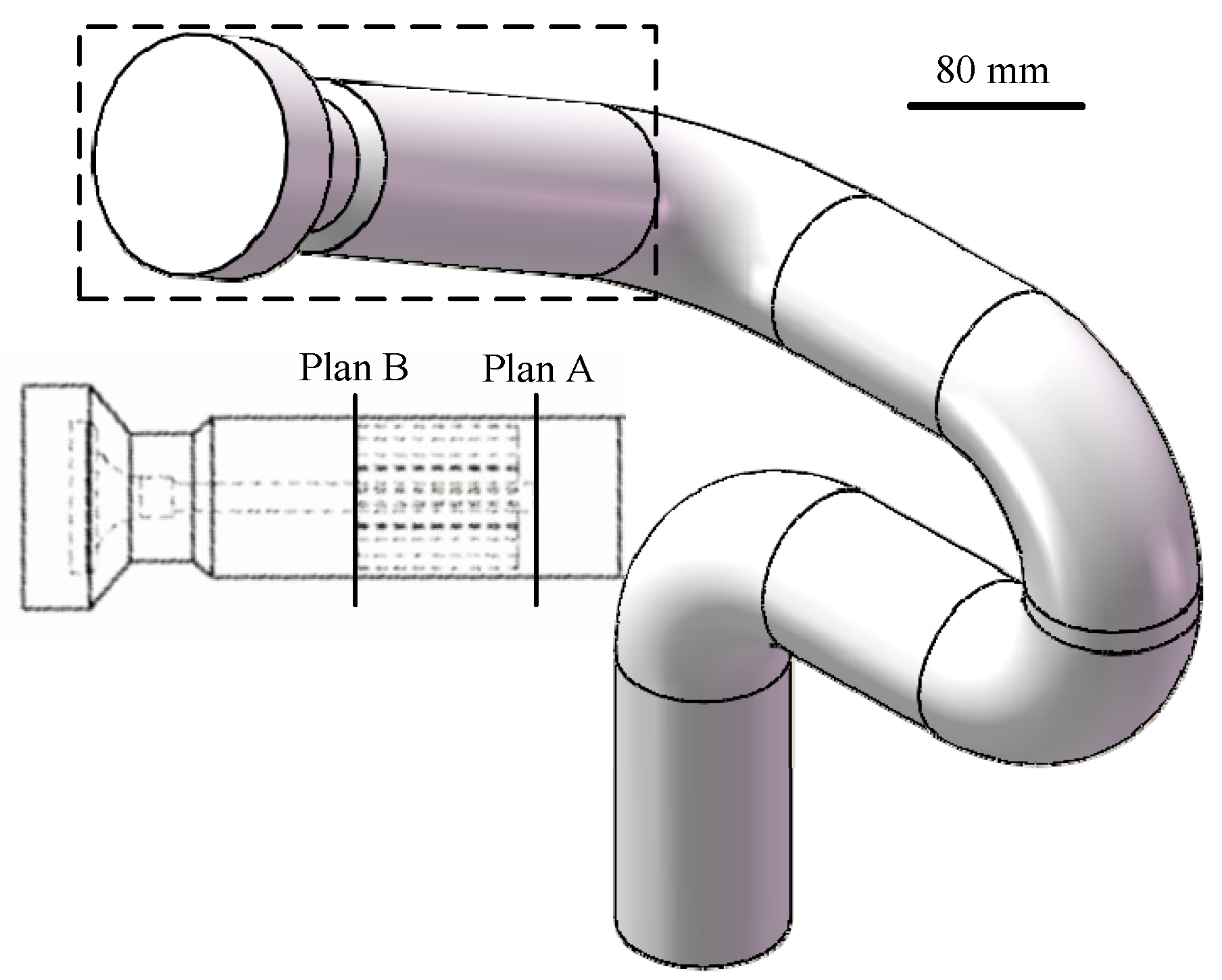
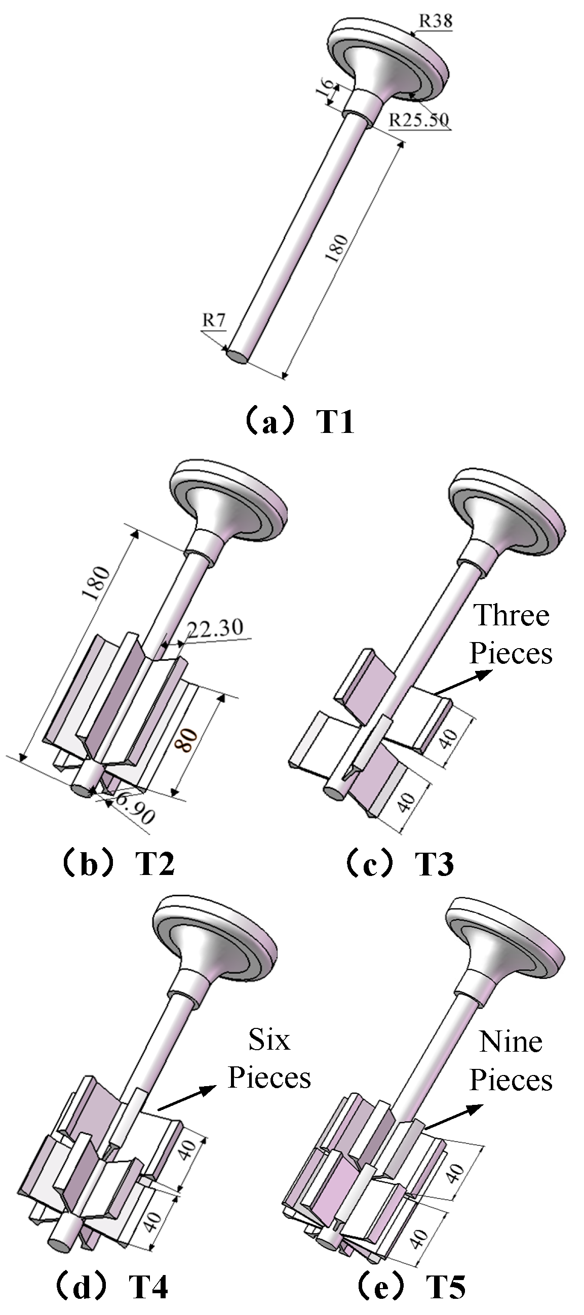
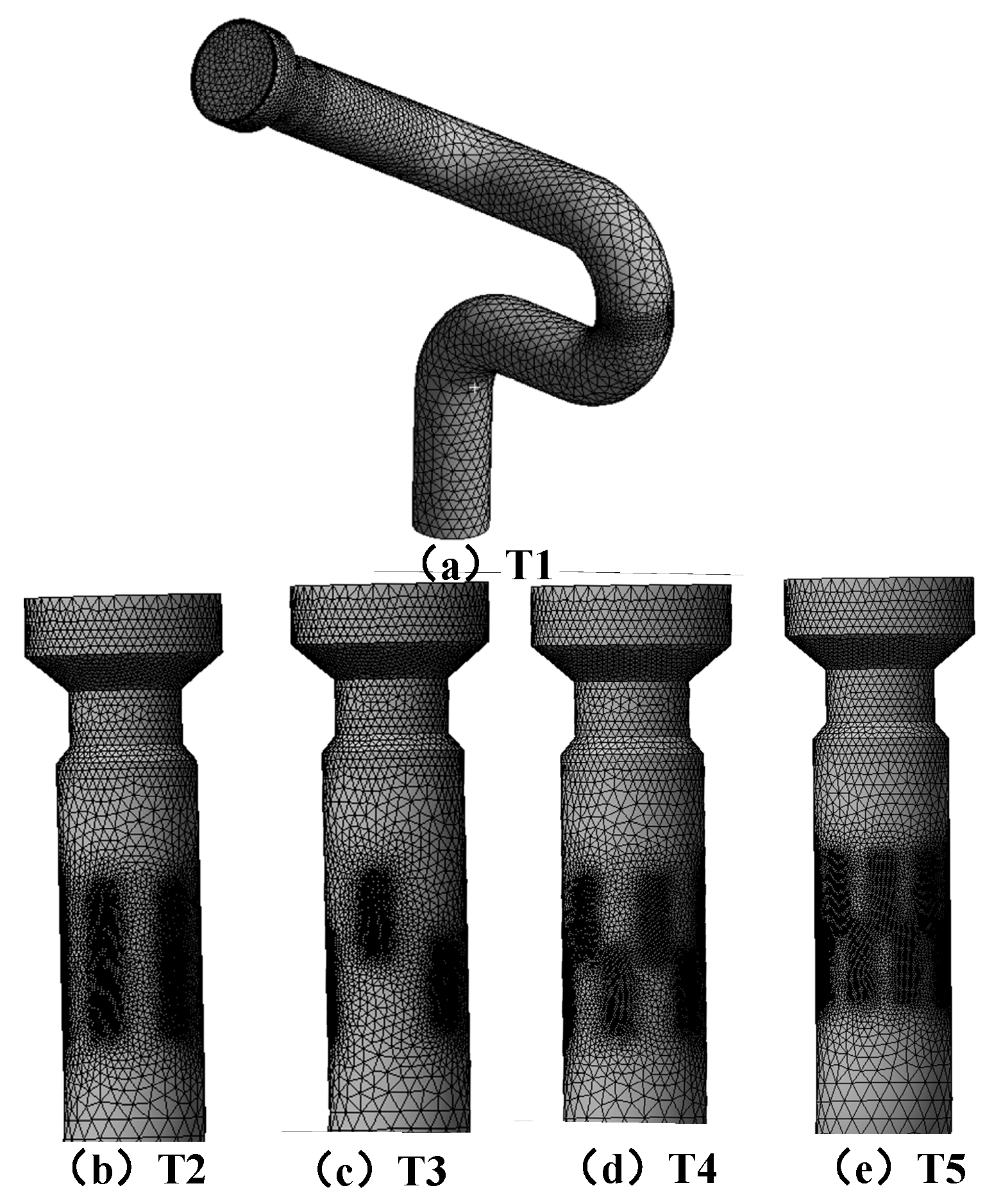
2.1. Geometric Model and Meshing

In this method, a specific model of firefighting monitor head is selected as the object of study, in which key parameters such as nozzle inlet, outlet diameter, throat radius, throat length, throat expansion and contraction angle of the firefighting monitor are certain. This paper mainly explores the influence of both the rectifier arrangement and the number of blades on firefighting monitor performance. A six-ribbed star rectifier of different lengths is installed at the end of the nozzle core of the firefighting monitor using Solidworks; the specific dimensions of the firefighting monitor and rectifier are shown in Figure 1. There are five types of flow stabilizers (T1–T5) in the firefighting monitor, as shown in Figure 2.
This paper uses the Meshing module of Ansys to mesh the physical model of the firefighting monitor, as shown in Figure 3; the number of meshes range from 700,000 to 1,100,000.

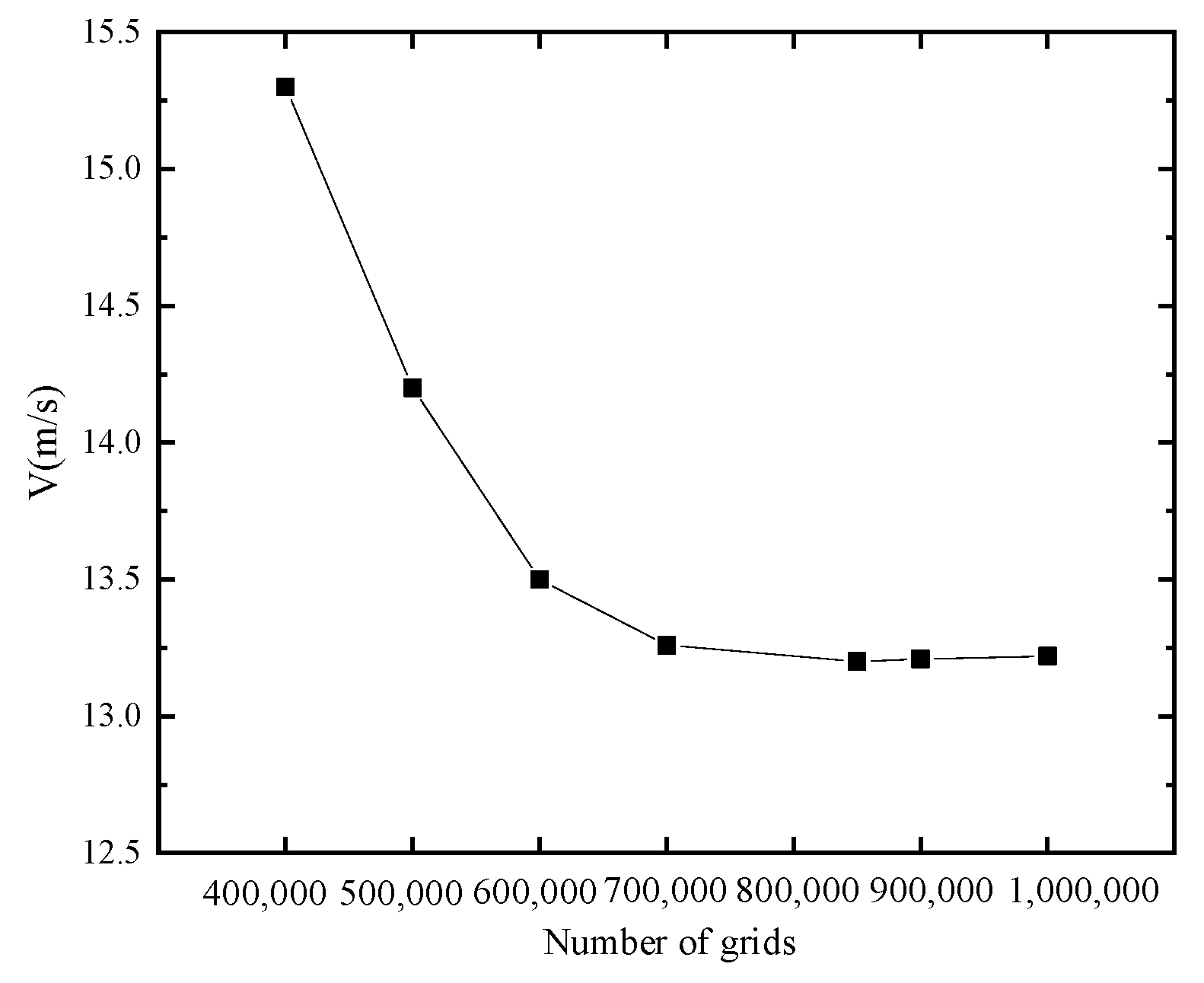
2.2. Grid Irrelevance Verification

A verification of the effect of the number size of the grid on the calculated results was carried out before studying the flow inside the firefighting monitor. As an example, the average velocity of section A is close to constant as the grid volume increases for a firefighting monitor with the T4 rectifier installed, as shown in Figure 4. In this paper, the grid number of 850,000 is chosen for numerical calculation.

2.3. Mathematical Model

In turbulent form, water flow is fast, and under high pressure. In this paper, the RNG k—ε model is chosen to simulate the flow of water in the pipe, and the k equation and ε equation are as follows:
ρ k t + ρ k u i x i = x i α k μ e f f k x j + G k + ρ ε
ρ ε t + ρ ε u i x i = x i α ε μ e f f ε x j + C 1 ε ε k G k C 2 ε ε 2 k
Among them:
u e f = u + u t ,   μ t = ρ C μ k 2 ε ,   η 0 = 4.377 ,   C 2 ε = 1.68 ,   E i j = 1 2 u i x j + u j x i
C μ = 0.0845 ,   α k = α ε = 1.39 ,   C 1 ε = 1.42
η = 2 E i j g E i j 1 2 k ε ,   β = 0.012
In these formulas, k is turbulent energy, ε is dissipation rate, ui is fluid flow velocity in the x-direction, ρ is fluid density and μ is the fluid viscosity coefficient.

2.4. Boundary Condition Setting

The inlet of the firefighting monitor model is the pressure inlet, which is set to 0.8, 1.0, and 1.2 Mpa; the outlet of the pipe is the pressure outlet, which is set to standard atmospheric pressure. The boundary condition of the wall is set to no slip, the coupled solution method of the pressure and velocity fields uses the SIMPLE algorithm, the relaxation factor of the iteration uses the software default value, and the convergence residual of each variable is set to 10−4.

3. Analysis and Discussion of Results

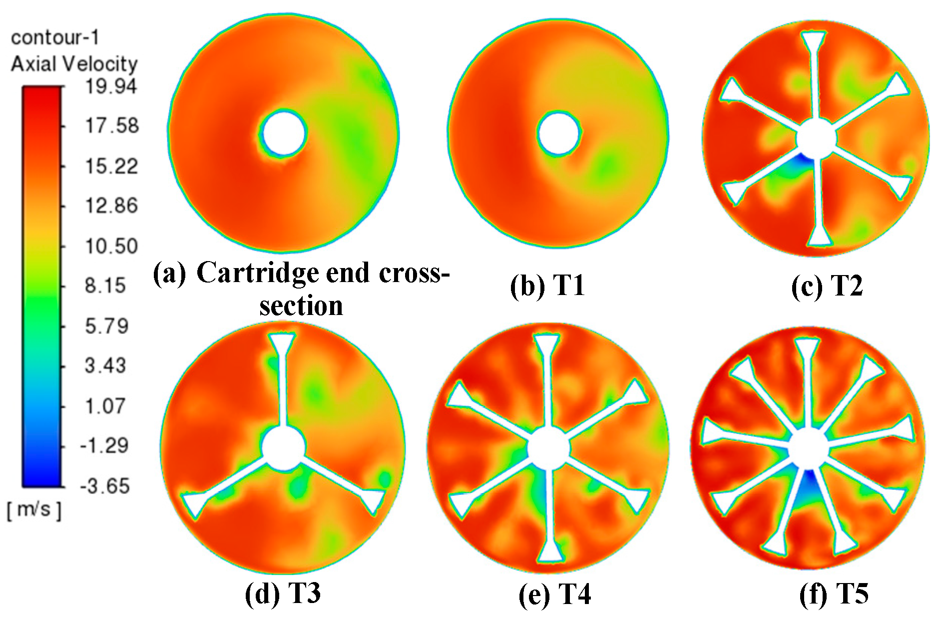
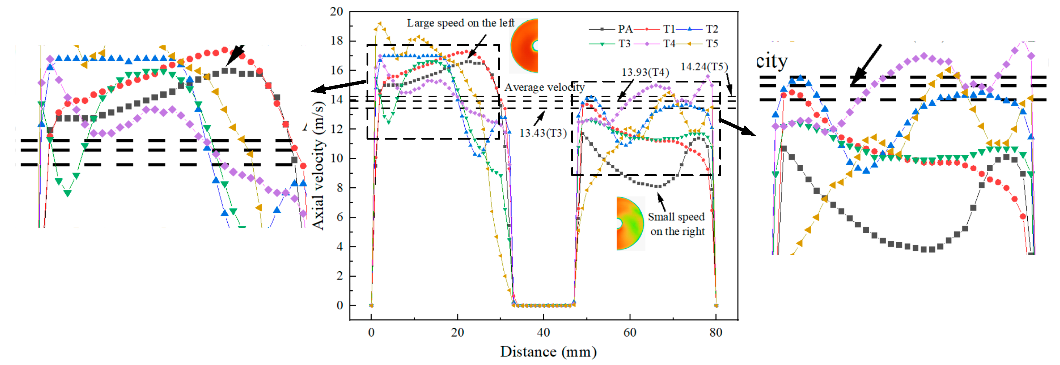
3.1. The Effect of Rectifier Structure on Axial Velocity

Numerical simulations were performed for firefighting monitors with different structures of rectifiers installed. Figure 5a shows the velocity flow diagram of a firefighting monitor without a rectifier. The streamlines in the diagram indicate the direction of velocity, and the color of the streamlines indicates the magnitude of velocity. We mainly observed the flow direction of the fluid in the pipe via the direction of the flow line in the diagram. The diagram shows that the water flow enters from the inlet of the water cannon and passes through four elbows while making bends and rotations [23]. When the fluid flows through the 90° bend, Dean vortices appear in the axial section, which can reflect fluid rotation and local loss [24]. When the stream reaches the straight pipe section of the outlet, it has high radial velocity and a large vortex, which in turn affects the range of the firefighting monitor. Figure 5d illustrates a streamline diagram of the velocity of the firefighting monitor with a type IV rectifier installed. After comparison, it is evident that the installation of a rectifier in a firefighting monitor can optimize the flow of fluid along the axis direction. Installing a flow stabilizer in a firefighting water cannon can reduce the flow vortex in the outlet section and make the axial velocity distribution of the outlet more uniform, thus improving the range of the firefighting water cannon and achieving hydraulic performance optimization.
The axial velocity of the fluid inside the firefighting monitor is an important factor affecting jet distance. In this paper, the axial velocities of firefighting monitors equipped with different types of rectifiers at plan A and plan B positions are compared and analyzed when inlet pressure is set to 1 Mpa, as shown in Figure 6.
The installation of a rectifier can improve the axial velocity distribution of the fluid in a firefighting monitor. As can be seen in Figure 6a, when the fluid does not flow through a rectifier, the axial velocity on the right side of the firefighting monitor is significantly smaller than the velocity on the left side. When no rectifier is installed (T1), as shown in Figure 6b, the uneven axial velocity of the fluid is does not improve and the velocity on the right side remains relatively small. When the type II star rectifier (T2) is installed (Figure 6c), the axial velocity on the right side of the fluid flowing through the rectifier significantly increases, but there is still a large area of low flow velocity between some of the blades. To further enhance the stabilization effect of the rectifier, the rectifier is divided into two sections of the same length and arranged crosswise so that the volume of the rectifier is certain, as shown in Figure 2d. When the fluid is flowing through plan B of the stabilizer, the axial velocity on the right side of T4 (forked row arrangement) is significantly greater than that of T2 (down-row arrangement). To improve the stabilization effect of the rectifier, the number of rectifier blades is changed based on the cross-arrangement of the rectifier. From the axial velocity clouds of T3, T4 and T5, it is clear that the steady flow performance of a rectifier is not proportional to the number of blades. As shown with T3 and T4, reducing the number of rectifier blades does not enhance the stabilization effect of the rectifier, as there is a large regional axis velocity gap. T4 and T5 demonstrate that there is a limit to improving the stabilization effect via increasing the number of blades in a rectifier. The right axis velocity of T5 had a slight increase, but localized fluid disturbance occurred in the center of the pipe, as well as reverse direction flow.
To better illustrate the stabilization effect of the rectifier, the axial velocities on the transverse axes of plan A and plan B are quantified and analyzed, as shown in Figure 7. When fluid is not flowing through the rectifier, the flow velocity on the left side is higher, with a maximum velocity of 17.3 m/s, while the velocity on the right side is smaller, with a velocity concentration of 10–11.5 m/s in the interval. When the fluid flows through the stabilizer, the average velocities of T3–T5 at plan B are approximately 13.43 m/s, 13.93 m/s and 14.24 m/s, respectively. It is clear from the Figure 7 that the flow velocity on the right side increases to different degrees after stabilizer installation; T4, a forked row, six-piece stabilizer, has the best stabilization effect. With a T4 rectifier, overall fluid velocity on both the left and right sides is closer to the average velocity, which significantly improves the uniformity of fluid velocity distribution.

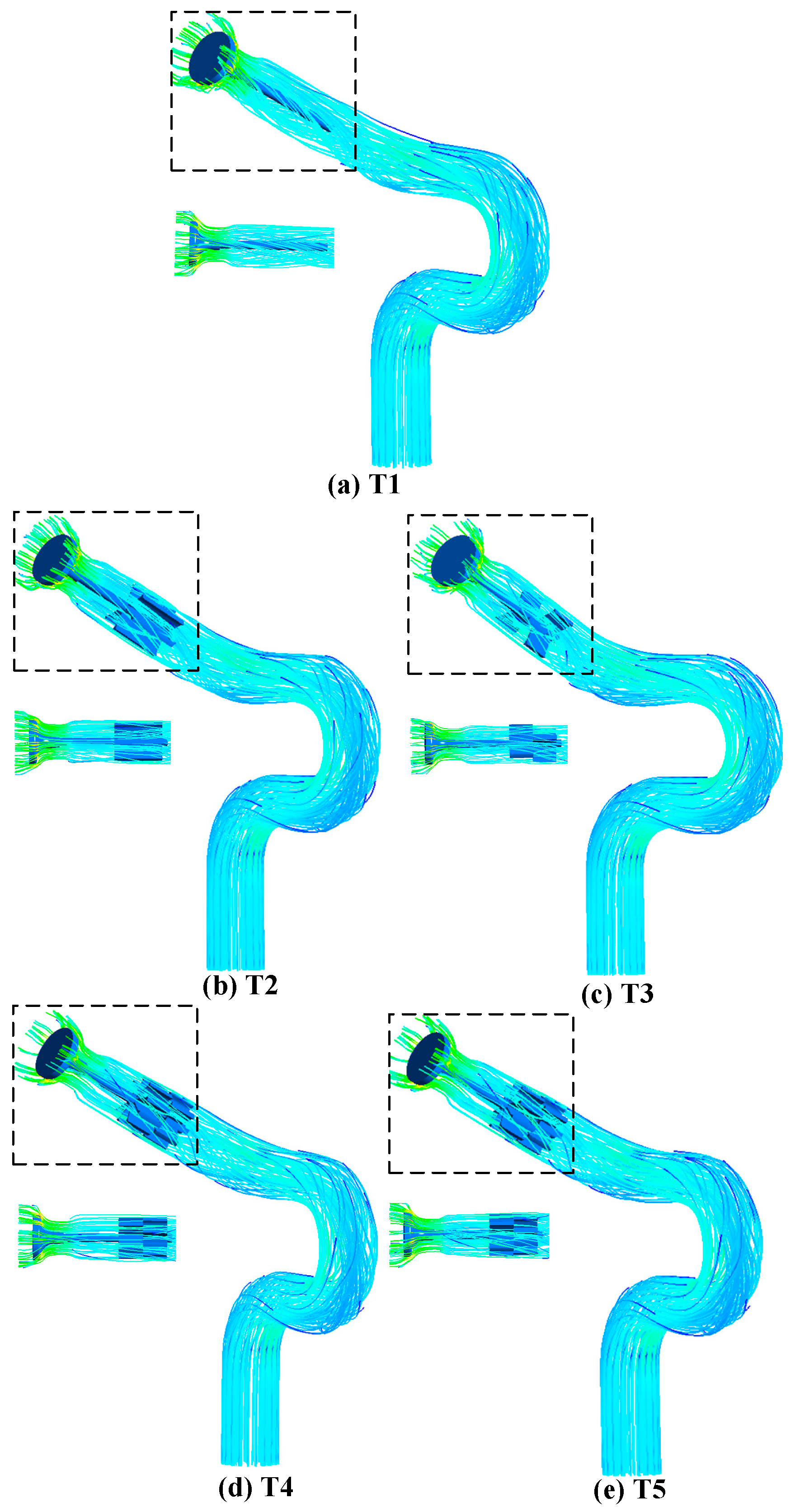
3.2. Reverse Flow and Vortex in Firefighting Monitors

In Figure 6 it can be seen that when the number of rectifier blades is increased to 9, the minimum fluid velocity near the center of the cross-section is −3.6 m/s. The vector analysis of this local area, as shown in Figure 8a, demonstrates a reverse flow with a vortex near a central wall position; the T4 rectifier, as shown in Figure 8b, has no reverse direction flow at its outlet section. When the fluid flows through the rectifier blade, the fluid flow rate drops and the pressure increases due to an obstructive effect, which forms a smooth pressure zone in front of the blade. When the fluid flows from both sides of the blade, the flow rate begins to increase, making the pressure behind the blade decrease, thus forming a back pressure zone behind the blade. The differential pressure distribution in front of and behind the rectifier vanes caused a reverse flow at the exit of the rectifier.

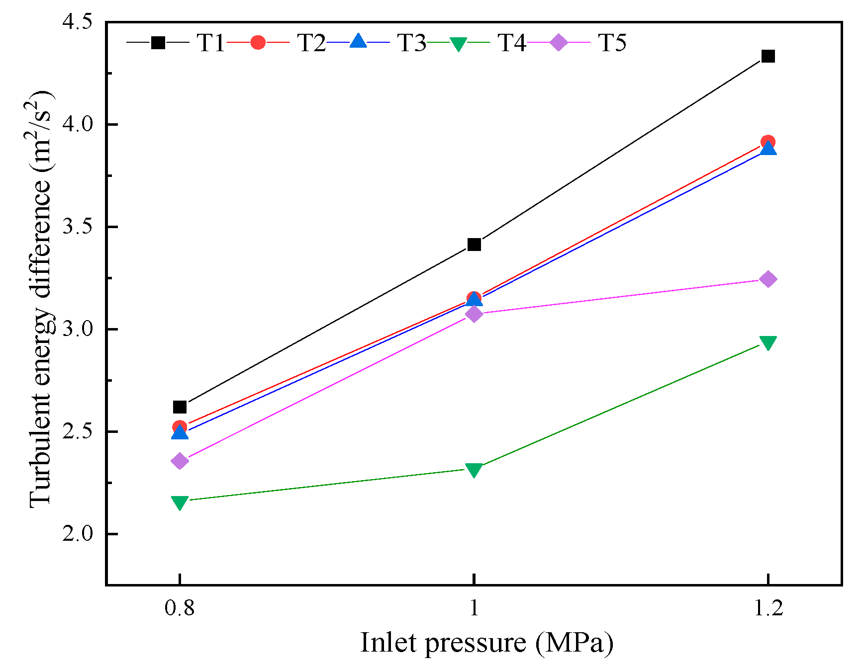
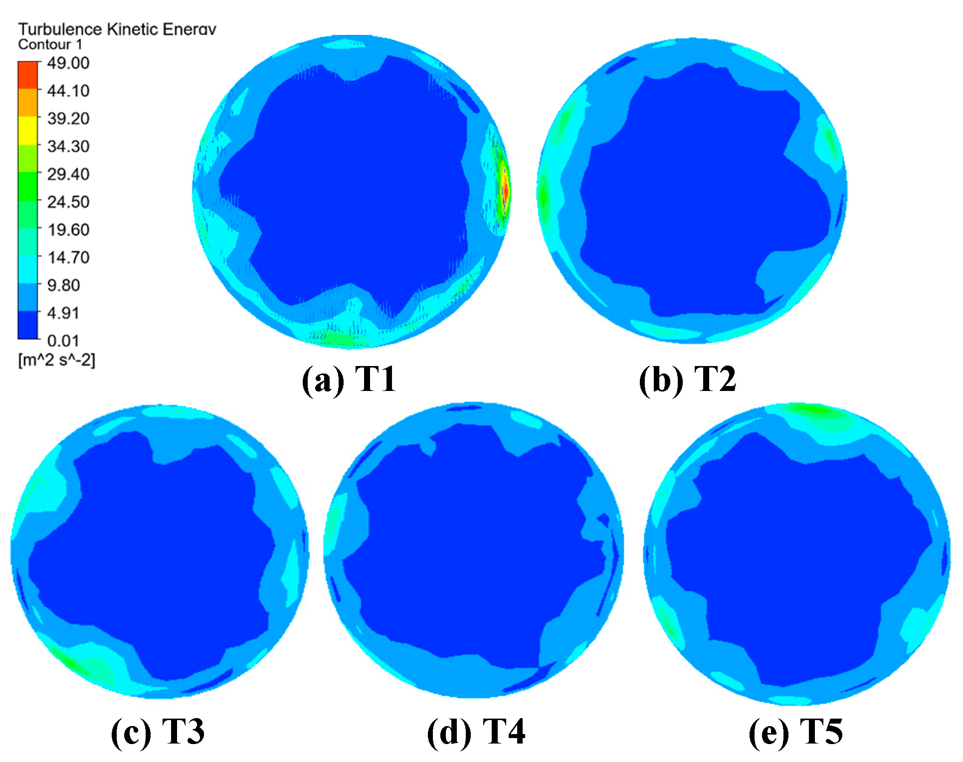
3.3. Effect of Rectifier Structure on Turbulent Energy and Pressure Drop of Firefighting Monitor

Outlet turbulence energy represents the turbulent pulsation kinetic energy per unit mass of fluid. This paper quantifies the turbulent energy values of the import and export of different types of firefighting monitors in order to further analyze the influence of rectifier type on firefighting monitor performance (all area-weighted).
As shown in Figure 9, installing a rectifier can reduce the turbulent energy of the inlet and outlet of a firefighting monitor to varying degrees. Using the working condition of 1 Mpa inlet pressure as an example, when a firefighting monitor does not have a flow stabilizer installed, the maximum turbulent energy difference between the import and export is 3.41 m2.s−2. In contrast, the turbulence energy of firefighting monitors equipped with four types of rectifiers was reduced; among these four the T4 firefighting monitor, with a turbulence energy of only 2.31 m2.s−2, showed the most significant reduction. Compared with the firefighting monitor without flow rectifiers, the difference in turbulence energy between the import and export of T4 was optimized by 32.3%. In addition, the turbulent energy of the import and export of firefighting monitors equipped with different types of rectifiers shows an upward trend as inlet pressure increases.
Figure 10 shows the turbulent kinetic energy clouds at the outlet of firefighting monitors equipped with different rectifiers. When the firefighting monitor does not have a rectifier installed, the export turbulent kinetic energy is larger and the nozzle exit wall has a high degree of turbulence and turbulence energy gradient change near the wall of the circular tube; this outflow accelerates the fragmentation of the jet. After the four rectifiers were installed, the turbulent energy at the outlet was greatly improved; among these four the rectification effect of T4 was the most obvious. The turbulent kinetic energy clouds show results that correspond to the conclusions of the data analysis.
In order to investigate the effect of different rectifiers on pressure loss inside firefighting monitors, the pressure variation between plan A and plan B was quantitatively analyzed: as shown in Figure 11, the installation of rectifiers increases the pressure loss inside the firefighting monitor. Not only does the forked row arrangement of the rectifier increase the pressure loss, but the pressure loss of the fluid increases as the number of rectifier blades increases. As shown in Figure 11, with 3 rectifier blades arranged in forked rows, the pressure loss is 23.5 kPa; with 9 rectifier blades arranged in crosses, the pressure loss reaches a maximum of 77.2 kPa. Therefore, in actual rectifier design, increasing the number of rectifier blades to enhance the performance of firefighting monitors should be limited, as too many blades will cause a large pressure loss.

4. Conclusions

In this paper, numerical simulations of firefighting monitors with different rectifier structures are carried out, and the turbulent energy of the inlet and outlet of the firefighting monitor and the axial velocity are analyzed, leading to the following conclusions:
(1)
The installation of a rectifier can improve axial velocity distribution within a firefighting monitor and reduce the turbulent energy of a firefighting monitor’s inlet and outlet.
(2)
A forked row rectifier arrangement can significantly improve its stabilization effect.
(3)
There are limits to improving rectifier stabilization performance by changing the number of blades; too many blades can cause reverse direction flow and large pressure losses.

Author Contributions

Conceptualization, J.Z. (Jiaqing Zhang); methodology, S.L.; validation, Y.H.; formal analysis, J.Z. (Jiaqing Zhang); investigation, Y.G.; resources, Y.G.; data curation, S.L.; writing—original draft preparation, J.Z. (Jiafei Zhang); writing—review and editing, D.L.; visualization, C.Z.; supervision, Y.H.; project administration, S.L. All authors have read and agreed to the published version of the manuscript.

Funding

This research was funded by the Science and Technology Project for State Grid Anhui Electric Power Co., Ltd. (No. 52120520005A) and Anhui Provincial Natural Science Foundation (No. 2008085UD13).

Data Availability Statement

The data that support the findings of this study are available from the author, [Jiafei Zhang], upon reasonable request.

Acknowledgments

This work was supported by the Science and Technology Project for State Grid Anhui Electric Power Co., Ltd. (No. 52120520005A) and Anhui Provincial Natural Science Foundation (No. 2008085UD13).

Conflicts of Interest

The authors declare no conflict of interest.

References

  1. Zhang, J.Q.; Li, G.H.; Wang, Y.L.; Li, C.H.; Shang, F.J.; Lu, S.X. Numerical simulation study of a typical extra-high voltage transformer fire. Fire Sci. Technol. 2020, 39, 1115–1120. [Google Scholar]
  2. Wang, Y.L.; Li, C.H.; Zhang, J.Q.; Shang, F.J.; Lu, S.X.; Fan, M.H.; Wang, L.F. Research on the characteristics of oil-immersed transformer fire accidents and countermeasures for fire extinguishing. Saf. Environ. Eng. 2019, 26, 166–171. [Google Scholar]
  3. Chen, T.; Zhao, L.; Fu, X.; Zhang, J.; Wang, Q.; Hu, C. Fire accident characteristics and firefighting solutions of large converter transformer. Fire Sci. Technol. 2020, 39, 1138–1141. [Google Scholar]
  4. Wang, H.F.; Chen, C.; Hu, L.; Wang, X.J. Reflection and prevention of transformer fire typical case. Distrib. Util. 2018, 35, 78–82. [Google Scholar]
  5. Zhao, Z.; Xu, Z.; Wang, J.; Guan, J.; Yu, X. Research on the fire safety of large power transformer. High Volt. Eng. 2015, 41, 3378–3384. [Google Scholar]
  6. Xu, J.; Yuan, S.; Xue, L.; Xiang, Q. Numerical simulation of internal flow in large-turning fire water cannon barrel with elliptical cross-sectional shapes. J. Drain. Irrig. Mach. Eng. JDIME 2022, 40, 39–397. [Google Scholar]
  7. Min, Y.; Chen, X.; Chen, C.; Hu, C. Pitching angle-based theoretical model for the track simulation of water jet out from water fire monitors. J. Mech. Eng. 2011, 47, 135–137. [Google Scholar] [CrossRef]
  8. Xin, Y.; Thumuluru, S.; Jiang, F.; Yin, R.; Yao, B.; Zhang, K.; Liu, B. An experimental study of automatic water cannon systems for fire protection of large open spaces. Fire Technol. 2014, 50, 233–248. [Google Scholar] [CrossRef]
  9. Liu, L.T.; Ma, Z.M. Study on influencing factors of nozzle performance of the fire water monitor. Energy Res. Inf. 2011, 27, 105–109. [Google Scholar]
  10. Yuan, X.M.; Wang, C.; Zhao, B.; Yang, Q.X. Review of hydraulic performance of fire water monitor. J. Mach. Des. 2017, 34, 1–8. [Google Scholar]
  11. Xue, L.; Yuan, S.Q.; Xiang, Q.J.; Xu, J. Analysis of outlet flow state of firefighting monitor rotary main structure. J. Drain. Irrig. Mach. Eng. JDIME 2020, 38, 378–383. [Google Scholar]
  12. Yuan, D.Q.; Shi, R.; Cong, X. Performance analysis of guide vane in long-rang fire-fighting water cannon. J. Drain. Irrig. Mach. Eng. 2017, 35, 333–339. [Google Scholar]
  13. Chandratilleke, T.T.; Nadim, N.; Narayanaswamy, R. Analysis of Secondary Flow Instability and Forced Convection in Fluid Flow Through Rectangular and Elliptical Curved Ducts. Heat Transf. Eng. 2013, 34, 1237–1248. [Google Scholar] [CrossRef]
  14. Wang, J.; Yong, X.S.; Liu, Y.W.; Lu, L. Performance study of the turbulence models in a two-dimensional U-bend duct. J. Eng. Thermophys. 2017, 38, 710–718. [Google Scholar]
  15. Laribi, B.; Youcefi, A.; Matene, E. Length Efficiency of the Etoile Flow Straightener: Numerical Experimentation. In Proceedings of the ASME—JSME—KSME 2011 Joint Fluids Engineering Conference, Hamamatsu, Japan, 24–29 July 2011; pp. 1–7. [Google Scholar]
  16. Hu, G.L.; Long, M.; Gao, Z.G. Jet characteristics analysis of fire water monitor’s nozzle. Chin. Hydraul. Pneum. 2012, 251, 93–97. [Google Scholar]
  17. Yuan, X.M.; Wang, C.; Zhu, X.; Yang, X.; Wang, C. Hydraulic Performance of Star-shaped Regulator and Its Improved Structure. Mach. Tool Hydraul. 2019, 47, 58–64. [Google Scholar]
  18. El Drainy, Y.A.; Saqr, K.M.; Aly, H.S.; Nazri Mohd, J.M. CFD Analysis of Incompressible Turbulent Swirling Flow through Zanker Plate. Eng. Appl. Comput. Fluid Mech. 2014, 3, 562–572. [Google Scholar] [CrossRef]
  19. Xiang, Q.J.; Xue, L.; Kim, K.Y.; Shi, Z.F. Multi-objective optimization of a flow straightener in a large capacity firefighting water cannon. J. Hydrodyn. 2019, 31, 137–144. [Google Scholar] [CrossRef]
  20. Hu, G.L.; Liu, S.H.; Li, G.; Xu, M. Effects of Straightener Structure of Fire Monitor on the Jet Performance. Chin. Hydraul. Pneum. 2015, 41–45. [Google Scholar]
  21. Xiang, Q.J.; Liu, J.; Ye, D.X.; Wang, X.K. Influence of splitter plate on the hydraulic performance of the curved barrel of firefighting water cannon. J. Mech. Sci. Technol. 2022, 36, 775–784. [Google Scholar] [CrossRef]
  22. Yan, H.; Ou, Y.; Nakano, K.; Xu, C. Numerical and Experimental Investigations on Intemal Flow Characteristic in the Impact Sprinkler. Irrig. Drain. Syst. 2009, 23, 11–23. [Google Scholar] [CrossRef]
  23. Yan, H.J.; Wang, M.; Yang, X.G.; Ouyang, J.; Yu, F.F. Effect of bulletshaped straightener on hydraulic performances in internal flow of the impact sprinkle. Trans. Chin. Soc. Agric. Mach. 2007, 40–43. [Google Scholar]
  24. Zhu, H.; Zhan, H.; Li, C.; Peng, B. Numerical investigation on the characteristics of dean vortices. J. Hunan Univ. Technol. 2009, 23, 58–62. [Google Scholar]
Figure 1. Physical model diagram of firefighting monitor.
Energies 16 03898 g001
Figure 2. Schematic diagram of the rectifiers in the firefighting monitor.
Energies 16 03898 g002
Figure 3. Geometric model meshing.
Energies 16 03898 g003
Figure 4. Grid independence verification.
Energies 16 03898 g004
Figure 5. Firefighting monitor streamline diagrams.
Energies 16 03898 g005
Figure 6. Cross-sectional axial velocity clouds of firefighting monitors with different rectifiers (a) velocity cloud of plane A without rectifier; (bf) velocity of plane B clouds for five types of rectifiers (T1–T5).
Energies 16 03898 g006
Figure 7. Cross-sectional axial velocity clouds of firefighting monitors with different rectifiers.
Energies 16 03898 g007
Figure 8. Firefighting monitor internal speed vector diagram.
Energies 16 03898 g008
Figure 9. Inlet and outlet turbulence energy of firefighting monitor with different rectifier.
Energies 16 03898 g009
Figure 10. Turbulent kinetic energy clouds at the outlet of firefighting monitors with different rectifiers installed.
Energies 16 03898 g010
Figure 11. Pressure variation in firefighting monitors with different rectifiers. (The red star is the pressure difference between plan A and plan B).
Energies 16 03898 g011
Disclaimer/Publisher’s Note: The statements, opinions and data contained in all publications are solely those of the individual author(s) and contributor(s) and not of MDPI and/or the editor(s). MDPI and/or the editor(s) disclaim responsibility for any injury to people or property resulting from any ideas, methods, instructions or products referred to in the content.

