Article

Investigation into Pressure Appearances and Hydraulic Fracturing Roof-Cutting Technology in Mining Working Face under Residual Pillars: A Case Study

1
College of Mining Engineering, Taiyuan University of Technology, Taiyuan 030024, China
2
Xuzhou Coal Mining Group Co., Ltd., Xuzhou 221116, China
3
Key Laboratory of Shanxi Province for Mine Rock Strata Control and Disaster Prevention, Taiyuan 030024, China
4
School of Materials Science and Engineering, Taiyuan University of Science and Technology, Taiyuan 030024, China
5
State Key Laboratory of Coal Resources and Safe Mining, Xuzhou 221116, China
6
Shaanxi Yanchang Petroleum Balasu Coal Industry Co., Ltd., Yulin 719000, China
*
Author to whom correspondence should be addressed.
Energies 2023, 16(9), 3914; https://doi.org/10.3390/en16093914
Submission received: 7 April 2023 / Revised: 29 April 2023 / Accepted: 3 May 2023 / Published: 5 May 2023

Abstract

:
Strong mining pressure disasters are prone to happen when the mining working face is under residual pillars (MWFRPs). The purpose of this study was to experimentally investigate and evaluate pressure manifestations and hydraulic fracture roof-cutting technology in the development of a working face under residual pillars using a physical model and numerical modelling tools. A scheme for hydraulic fracturing cutting technology was proposed and carried out on-site at the 31106 working face. The results show that the instability of the overlying residual pillar causes the upper thick, hard strata (THS II) to rupture and form a “T-shaped structure”. The rotation and sinking movement of the structure leads to the transmission of the dynamic load downwards, causing shear failure in the lower thick, hard strata (THS I) along the boundary of the residual pillar. The smaller the length of the THS II fracture block, the smaller the shear damage of THS I, and the lesser the mining pressure in the working face. Field trials proved that hydraulic fracture roof cutting can effectively destroy the integrity of the thick hard strata and promote their collapse, which reduces the strong dynamic load borne by the hydraulic support. This research provides a reference for safe mining at a working face under similar conditions.

1. Introduction

Coal seams have the characteristics of a shallow burial, simple geological conditions, and multiple coal-seam mining in the western mining areas of China [1,2,3]. In the early stages of mining, the upper coal seams were extracted using room-and-pillar mining or fully mechanized mining methods, which left a large number of residual coal pillars. When the lower coal seams are mined underneath the upper residual pillars, it is easy for this to cause disasters, such as roof caving, support crushing, and water inrush, which seriously affect safe production [4,5,6,7]. In particular, when the mining working face is under residual pillars (MWFRPs), a large area of the roof collapses, resulting in a rapid influx of methane and other hazardous gases from the goaf into the working face, which easily causes explosions from dust–methane–air mixtures, and fire hazards occur in working developments that pose a threat to the life and safety of miners [8,9]. Therefore, conducting research on the appearance of mining pressure and understanding the control technology for MWFRPs is of great significance.
The strong mining pressure mechanism for MWFRPs has always been a main research topic. According to a lot of analyses on support crushing accidents in the Shendong mining area in China, Xu and Zhu [10,11,12] proposed that the reason for the impact dynamic load on the working face is the combination rupture of the double key strata, which is caused by the instant rotation instability of the key block above the residual pillar during WFMRP-type mining. Wang et al. [13] used the cusp catastrophe theory to analyze the instability mechanism of the room pillar and believed that the room pillar formed a chain of instability under the disturbance of lower coal-seam mining, which led to a large number of roof collapses and support-crushing disasters. Guo et al. [14] established a FLAC3D numerical model to study the stress distribution of the longwall working face during mining under residual pillars and goaf, and found that the stress beneath the boundary of the coal pillar was higher than that beneath the middle. The stress range at the edge of the coal pillar was 10 m. Zhou et al. [15] established a mechanical model to study the zoning characteristics of MWFRP mining pressures. Huo et al. [16] discussed MWFRPs’ overburdened roof structures and revealed the combined dynamic action compression mechanism of “high stress-coal pillar-overlying strata movement” in the lower coal seam working face under the influence of the residual pillar. Tian et al. [17] created a physical model to study overburden movement and stress evolution in multiseam mining with residual pillars. Fu et al. [18] employed theoretical analysis and on-site measurement methods to study the overlying rock structure and dynamic characteristics of MWFRPs, and the results show that, under large leading support stress, the upper residual coal pillars become unstable under the action of an advanced abutment pressure, leading to widespread fractures in the overlying strata and the transfer of the dynamic load to the lower working face. Moreover, many scholars have carried out extensive research on the instability of residual pillars [19,20,21,22]. Tian et al. [23] adopted simulation and engineering test methods to study the instability timing problem of residual coal pillars under mining disturbance. Based on the pressure arch theory, Hashiba and Fukui [24] analyzed the stability of room coal pillars, and the results indicated that the failure of a single pillar causes the overburden of the load to be transferred to an adjacent pillar. This lateral transfer effect of overburdened loads results in group failures of the pillars, leading to a large-scale collapse of the roof. Zhou et al. [25,26] gave experimental and numerical results on the failure process of double-pillar specimens and found that the magnitude of the dynamic disturbance to adjacent pillars was closely related to the extraction time of the residual pillar. Dong et al. [27] conducted a series of compressive tests on treble-pillar specimens under soft and stiff loading conditions in order to reveal the load transfer mechanism among pillars and to optimize the design of room-and-pillar stopes during underground mining.
Many scholars have proposed measures, such as presplitting blasting, grouting filling, increasing the support resistance, and accelerating the mining speed to control strong mining pressure in MWFRPs [28,29,30,31]. However, hydraulic fracturing has been initiated in the oil industry and is now being used widely in the coal mining industry as a relief technology for hard roof strata [32,33,34]. Jeffrey and Mills described the first successful use of hydraulic fracturing to induce a goaf event and control the timing of caving events in Moonee Colliery, Australia [35]. Klishin et al. developed a scheme for roof weakening with directional hydraulic fracturing technology at the longwall exit from the installation chamber to reduce the rock-heaving intensity in the development opening of the following longwall face in the S.M. Kirov Mine, Russia [36]. Jendry et al. analyzed the effectiveness of directional hydraulic fracturing as a method of rock-burst prevention, which was used in the “Rydultowy” Black Coal Mine (Upper Silesia, Poland) on a longwall system [37]. Based on previous studies and numerical modeling, He et al. [38] studied the prescribed hydraulic fracture propagation and reorientation process by considering the in situ stress and mechanical rock properties. Zhang et al. [39] concluded that roof cutting with a vertical hydraulic fracture at a specified position, also known as fixed-length roof cutting, can reduce the support load and keep the immediate roof intact. Liu et al. [40] proposed a directional hydraulic fracturing roof-cutting technology for controlled rock bursts induced by thick, hard roofs and residual coal pillars under repeated mining in close coal seam groups. Gao et al. [41] presented a method for subjecting hard roofs to ground fracturing in the Datong mining area in China, and physical simulations were used to study the control effect of ground fracturing on strata structure and energy release. Yang et al. [42] proposed a technology for weakening and relieving stress via a high-pressure water jet to solve the problem of strong ground pressure behavior under a residual coal pillar in the overlying goaf of a close-distance coal seam. The aforementioned studies, as well as the successful application of hydraulic fracturing technology, provide valuable references for the control of strong mining pressures in MWFRPs.
The purpose of this paper is to experimentally investigate and evaluate the pressure manifestation and cutting technology regarding hydraulic roof fractures for the development of a working face under residual pillars using a physical model and numerical modeling tools. A scheme for hydraulic fracturing cutting technology was proposed and was carried out on-site at the 31106 working face.

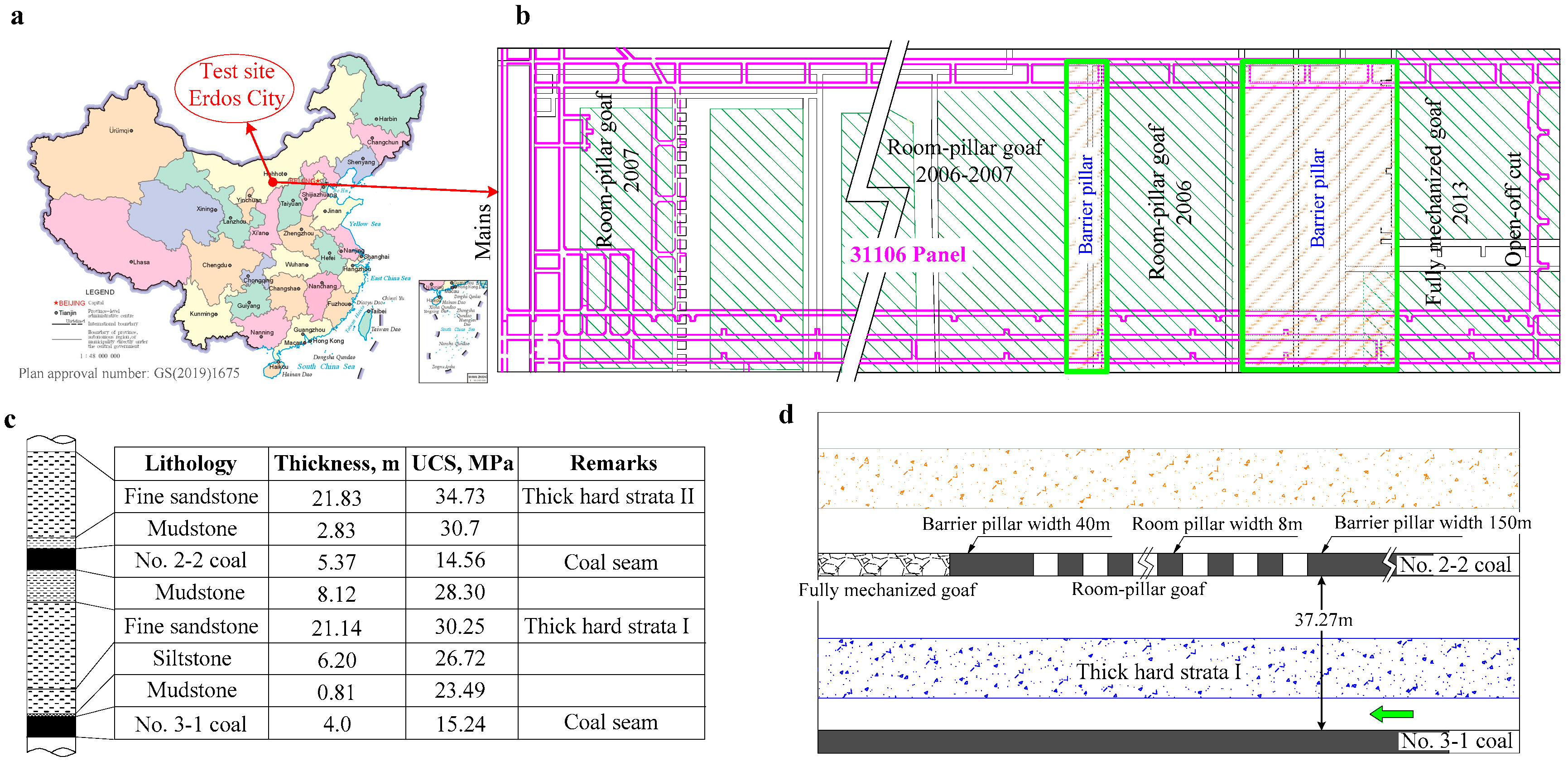
2. Engineering Background

2.1. Geological Conditions

The Huoluowan coal mine is situated in Ordos, Inner Mongolia, China (Figure 1a). Panel 31106 is 240 m wide and 3365 m long and primarily extracts the 3-1 coal seam using fully mechanized mining with the full-height method (Figure 1b). The 3-1 coal seam is nearly horizontal with a dip angle of 2–4°. The average buried depth and thickness are 180 m and 4 m, respectively. The generalized stratigraphy column is presented in Figure 1c. The 3-1 coal seam roof is composed of mainly fine sandstone, with a thickness of 21.14 m and a uniaxial compressive strength of 30.25 MPa (THS I). The upper 2-2 coal seam is 5.37 m thick, and its main roof is 21.83 m thick, made of fine sandstone with a uniaxial compressive strength of 34.73 MPa (THS II). The vertical distance between these two coal seams is 37.27 m. The 2-2 coal seam was mined using the room-and-pillar fully mechanized mining method from 2000 to 2017, resulting in a large number of residual coal pillars left behind. During the mining of the 31106 panel, work needs to pass through the upper residual coal pillars (Figure 1d). Moreover, it will be affected by two thick and hard strata (THS I and THS II), which will result in significantly strong mining pressures in the working face.

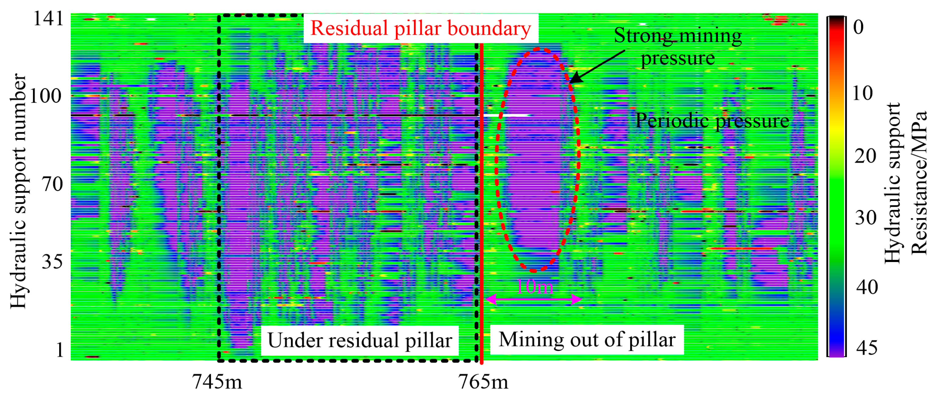
2.2. Mining Pressure Characteristics

The hydraulic support resistance real-time online monitoring system was installed to monitor the support resistance. Figure 2 shows the contour of the hydraulic support resistance during 31106 working face mining under the residual pillar with a width of 20 m. When the working face is under the pillar, the support resistance is distributed within the range of 40–45 MPa by 44.7%, and the safety valve opening rate reaches 21.3% (the safety valve opening pressure set at 43 MPa), which is characterized by continuous high-static loads. When the working face is below the pillar boundary, the distribution of support resistance within the range of 40–45 MPa increases to 66.7%, and the safety valve opening rate increases to 31.2%. A large-scale and strong pressure surge occurs when the working face advances out of the upper pillar boundary (about 10 m away), where the proportion of support resistance exceeding 40 MPa reaches 70.9%. As the working face advances under the fully mechanized goaf area, the normal periodic pressure is restored. Therefore, the appearance of strong mining pressure in MWFRPs can potentially cause support crushing accidents.

3. Physical Simulation of Pressure Appearances in MWFRPs

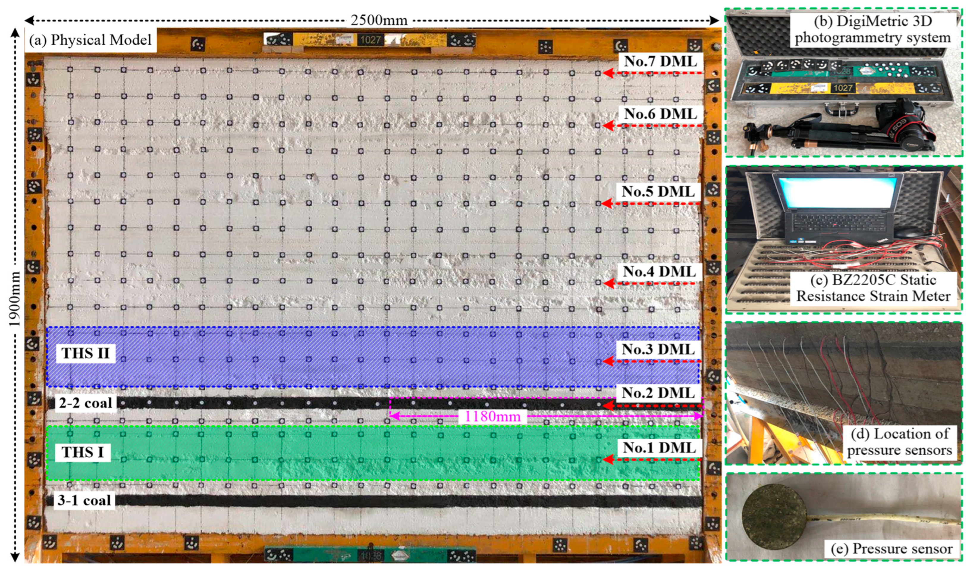
3.1. Physical Model Design

A physical model was established based on the geological conditions of the 31106 panel to study the pressure appearance in MWFRPs, as depicted in Figure 3a. The physical model has dimensions of 2500 mm in length, 1900 mm in height, and 200 mm in thickness. The similarity ratios used in the physical simulation were a geometric similarity ratio α L = 1:100, a bulk density similarity ratio α γ = 1:1.5, and a stress similarity ratio α r = 1:150 ( α L × α γ ). The physical model was horizontally placed from the floor of the 3-1 coal seam to the top of the model, including 22 layers and simulating a depth of 190 m. There is no external load applied to the top of the model. The width of the 2-2 coal seam mining area is 118 m (room pillar width is 8 m; coal room width is 6 m, with a total of 8 room pillars and 9 coal rooms), and the barrier coal pillar area is 100 m long. The strata were simulated using similar materials, which include natural river sand as the aggregate, lime (CaCO3) and gypsum as the cementing materials, water as the cohesive agent, and muscovite powder as the bedding interface. According to the mechanical properties of each rock layer in the stratigraphic prototype, the appropriate proportion (matching number) was selected, and Equation (1) was used to calculate the amount of each layer of material in the model, respectively. The proportioning parameters of the rock strata in the physical model are listed in Table 1.
G = l b h γ m
G is the model delamination material quality, kg; l is the model length, m; b is the model width, m; h is the thickness of each layer in the model, m; γm is the bulk density of each layer in the model, kg/m3.
The excavation of the model was divided into two steps. Firstly, the 2-2 coal seam was excavated from left to right to form eight room pillars. Next, the 3-1 coal seam was excavated from left to right through the upper residual coal pillars. The displacement of the overlying strata caused by mining was monitored using the DigiMetric 3D photogrammetry system (Figure 3b). A total of seven strata vertical displacement monitoring lines (DML) were set up. Mining stress was monitored during the excavation process using the BZ2205C programmable static electric resistance strain gauge data acquisition system and the BW-type flat-pressure sensor (Figure 3b–d).

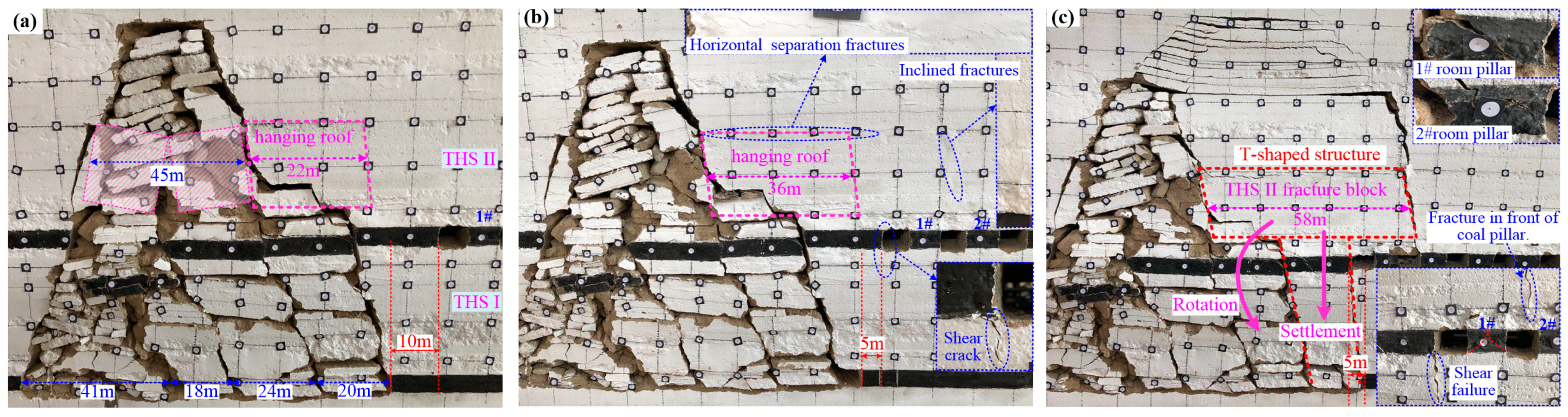
3.2. Overlying Strata Fracture Characteristics

The characteristics of the overlying strata fracture for MWFRPs are illustrated in Figure 4. Following the excavation of the 2-2 coal seam, the room pillars and THS II remained stable. When the 31106 working face advanced 83 m, THS II ruptured first with a span of 45 m (Figure 4a). When the 31106 panel advanced to a distance of 10 m from the boundary of the barrier pillar (Stage I), the working face experienced the third period of pressure, causing THS I to fracture and its upper rock layer to collapse onto the lower surface of THS II. A hanging roof 22 m long was formed by THS II at the edge of the barrier pillar (Figure 4a). As the 31106 working face continued to be excavated to a distance of 5 m from the boundary of the barrier pillar (Stage II), the hanging roof length of THS II increased to 36 m. Obvious horizontal separation fractures appeared at the upper surface of THS II, and tiny inclined fractures developed between the #1 and #2 room pillars. Simultaneously, vertical shear fractures occurred along the edge of the barrier pillar, and the hanging roof structure of THS II transmitted stress downward through the coal pillar (Figure 4b). When the 31106 working face advanced to a position 5 m away from the barrier pillar boundary (Stage III), the #1 and #2 room pillars became unstable under high abutment stress, losing their load-bearing capacity and causing an increase in the span of THS II above the room-and-pillar goaf. THS II ruptured above the #1 and #2 room pillars, and the length of the hanging roof fracture reached 58 m. The THS II cantilever formed a “T-shaped structure” under the support of the barrier pillar (Figure 4c). The “T-shaped structure” controlled the overall sinking of the upper rock layer, turning it toward the goaf while transmitting loads to the lower working face through the barrier pillar. This resulted in the vertical shear failure of THS I along the edge of the barrier pillar, leading to a wide range of increases in the hydraulic support resistance of the 31106 working face. This situation can easily cause support-crushing accidents in MWFRPs.

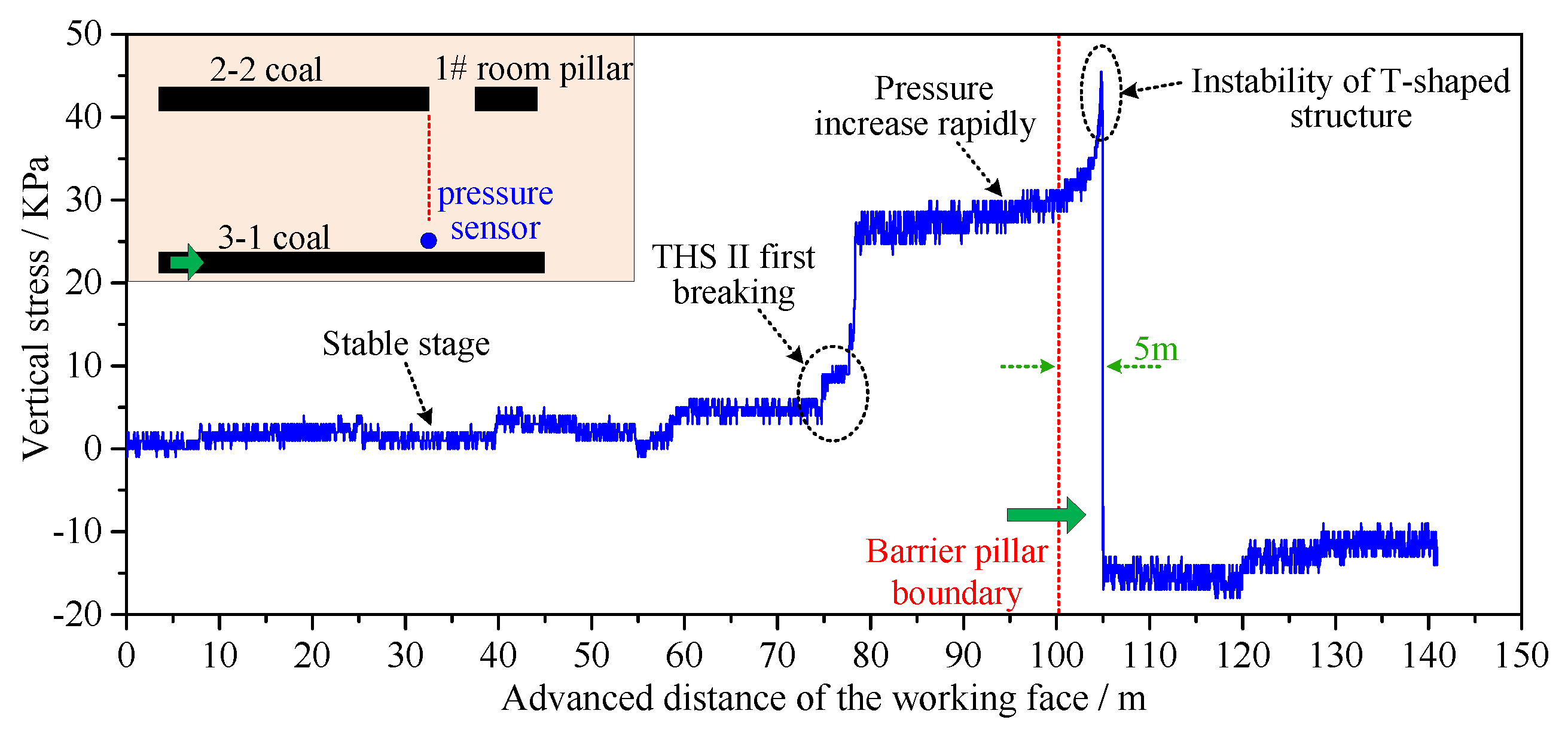
3.3. Evolution Characteristics of Mining Stress

Figure 5 presents the stress curve of the 3-1 coal roof in MWFRPs. It is evident that the stress was in a stable stage after the room-pillar excavation of the 2-2 coal seam. However, when the 31106 working face advanced, causing the first breaking of THS II, the stress increased from 4.86 kPa to 9.98 kPa, which indicates that the THS II fracture had an impact on the lower 31106 working face. Furthermore, the hanging roof formed by THS II transmitted the load to the lower working face. The stress rapidly increased from 9.98 kPa to 26 kPa and continued for a distance of 20 m in the high-pressure interval. As the 31106 working face advanced to a position 5 m away from the barrier pillar boundary, the unstable “T-shaped structure” formed by THS II caused the fracture of THS I, which resulted in the stress increasing to 46 kPa, which was an increase of 70.4% compared to before the excavation without the upper barrier pillar. The working face continued to move away from the coal pillar, and the stress rapidly decreased, indicating a significant dynamic load impact during the period of mining under the residual coal pillars.

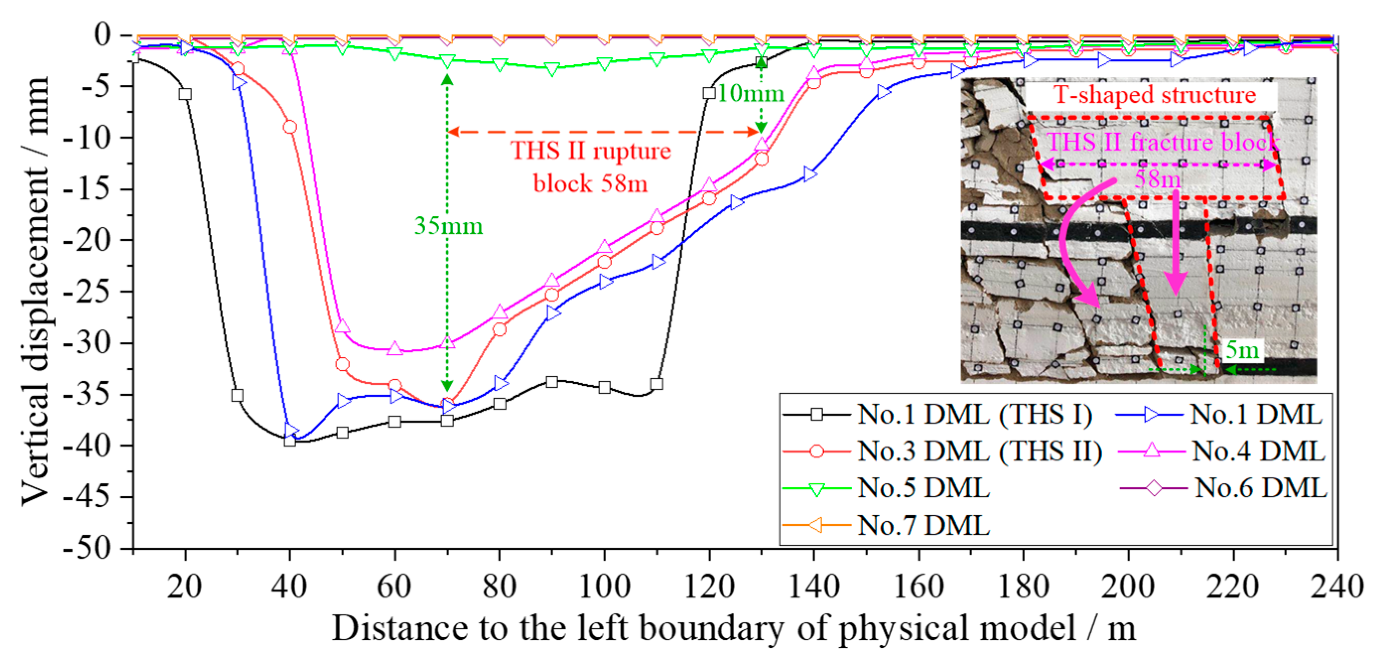
3.4. Displacement of Overlying Strata

Figure 6 shows the vertical displacement curve of the overlying strata for MWFRPs. It can be seen that THS II ruptured above the #1 and #2 room pillars, forming a ruptured block with a length of 58 m, which further rotated and sunk. The sinking was 10 mm (actual 1.0 m) at the fracture line position and 35 mm (actual 3.5 m) at the free end, causing a barrier pillar sinkage of 20 mm (actual 2.0 m). THS I vertically cut along the edge of the barrier pillar, and the displacement reached 34 mm (actual 3.4 m), accounting for 85% of the 3-1 coal seam mining height. Therefore, the rupture of THS II caused THS I to collapse and generated dynamic loading effects, which can easily cause support-crushing accidents.

4. Numerical Simulation of the Influence of Rupture Length of THS II

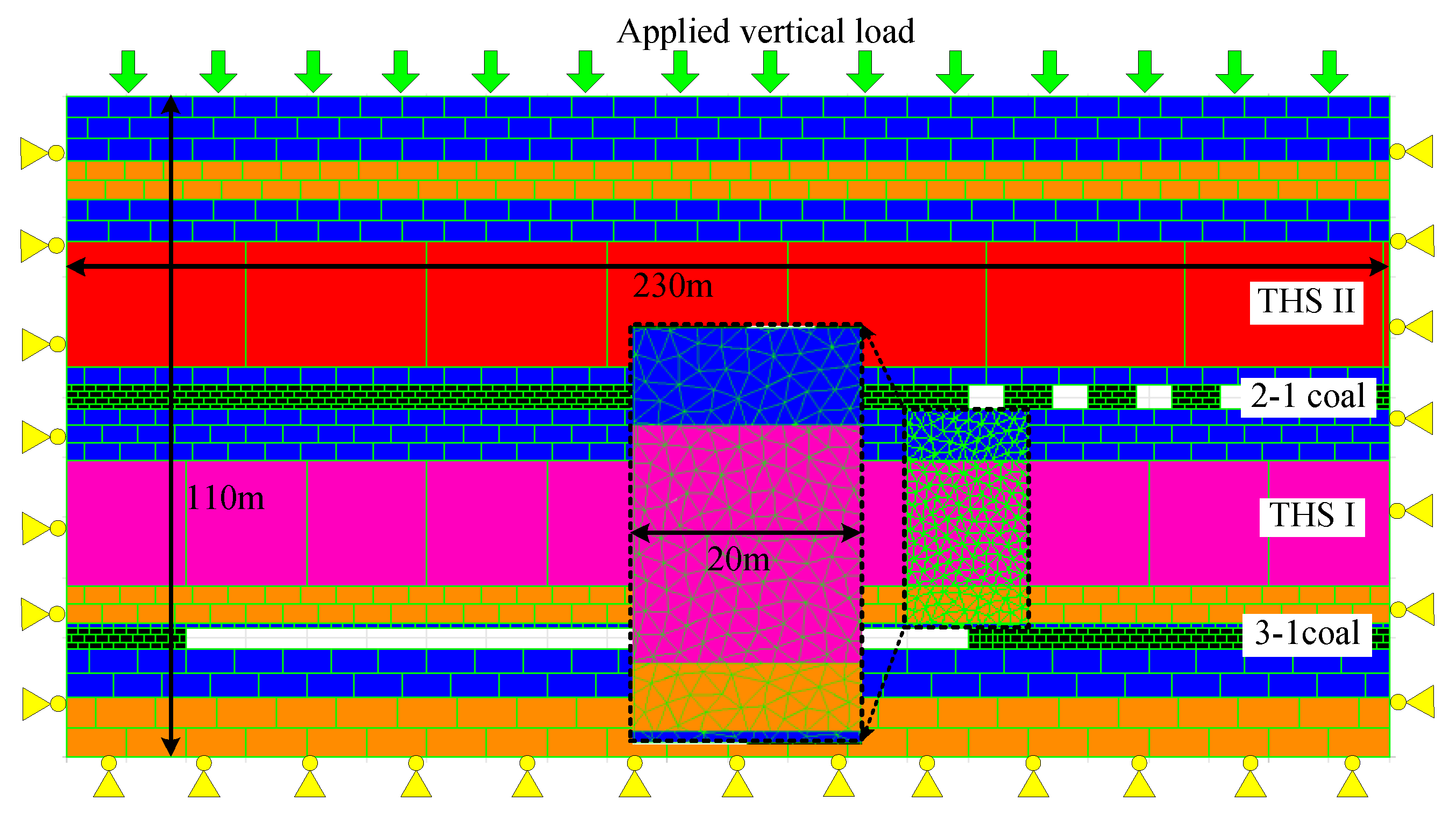
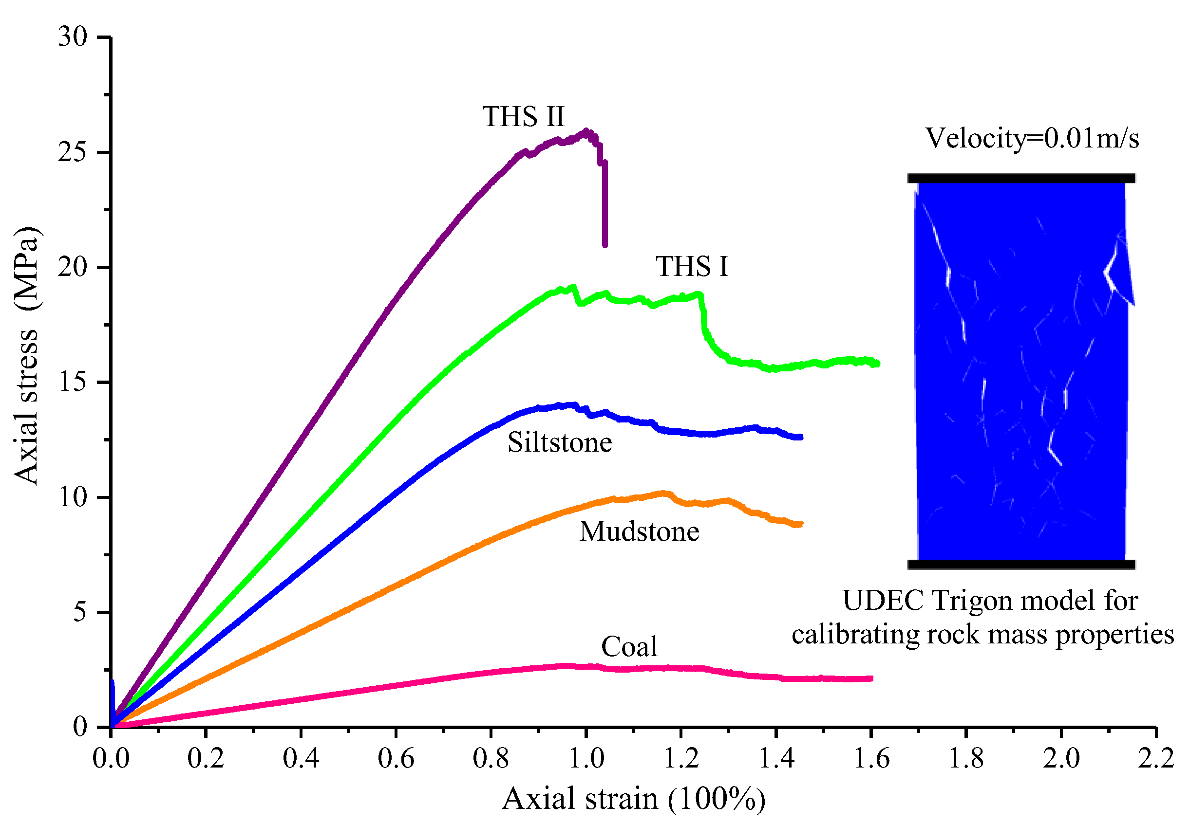
4.1. Model Construction

Two-dimensional UDEC software was used to analyze the influence of the hanging length of THS II on the appearance of mining pressure in the 31106 working face. The model size was 230 m in length and 110 m in height, as shown in Figure 7. In order to improve computing efficiency, UDEC Trigon logic was used to generate triangular blocks in the area of interest (strata) between the two layers of the coal seam. The average edge length of these triangular blocks was set at 2 m to capture the shear damage of the strata. The bottom and lateral boundaries were fixed in displacement in the vertical and horizontal directions, respectively. The state of in situ stress obtained through the in situ stress measurement of σ V = 4.35 MPa, σ h = 3.70 MPa and σ H = 6.29 MPa was applied to the model [43]. σ H is parallel to the longwall advance direction, and σ h is perpendicular to the longwall advance direction. A vertical stress of 2.25 MPa was applied on the upper model boundary, which is equivalent to the overburden weight. Each triangular block is assumed to be elastic material and is divided into triangular finite difference zones that cannot fail in the model. Failure caused by shear or tensile stress can only occur along the contacts, depending on the strength of the contact surface. Mechanical interactions between two triangular blocks are controlled by the Mohr–Coulomb criteria.
A series of uniaxial compressive strength tests were conducted using UDEC Trigon logic to calibrate the rationality of the micromechanical parameters of the coal mass and the rock mass. Figure 8 displays the calibrated stress-strain curves obtained from the unconfined compression tests. The calibrated properties in the numerical model are listed in Table 2. In order to monitor the failure of THS I for MWFRPs, a FISH function was used to record the total length of cracks in THS I, as well as the length of shear cracks caused by mining-induced stress. The damage parameter was set according to Gao [44]. The variation in THS I shear damage was studied under the three stages, with the rupture block length of THS II above the barrier pillar set to 50 m, 40 m, and 30 m, respectively.

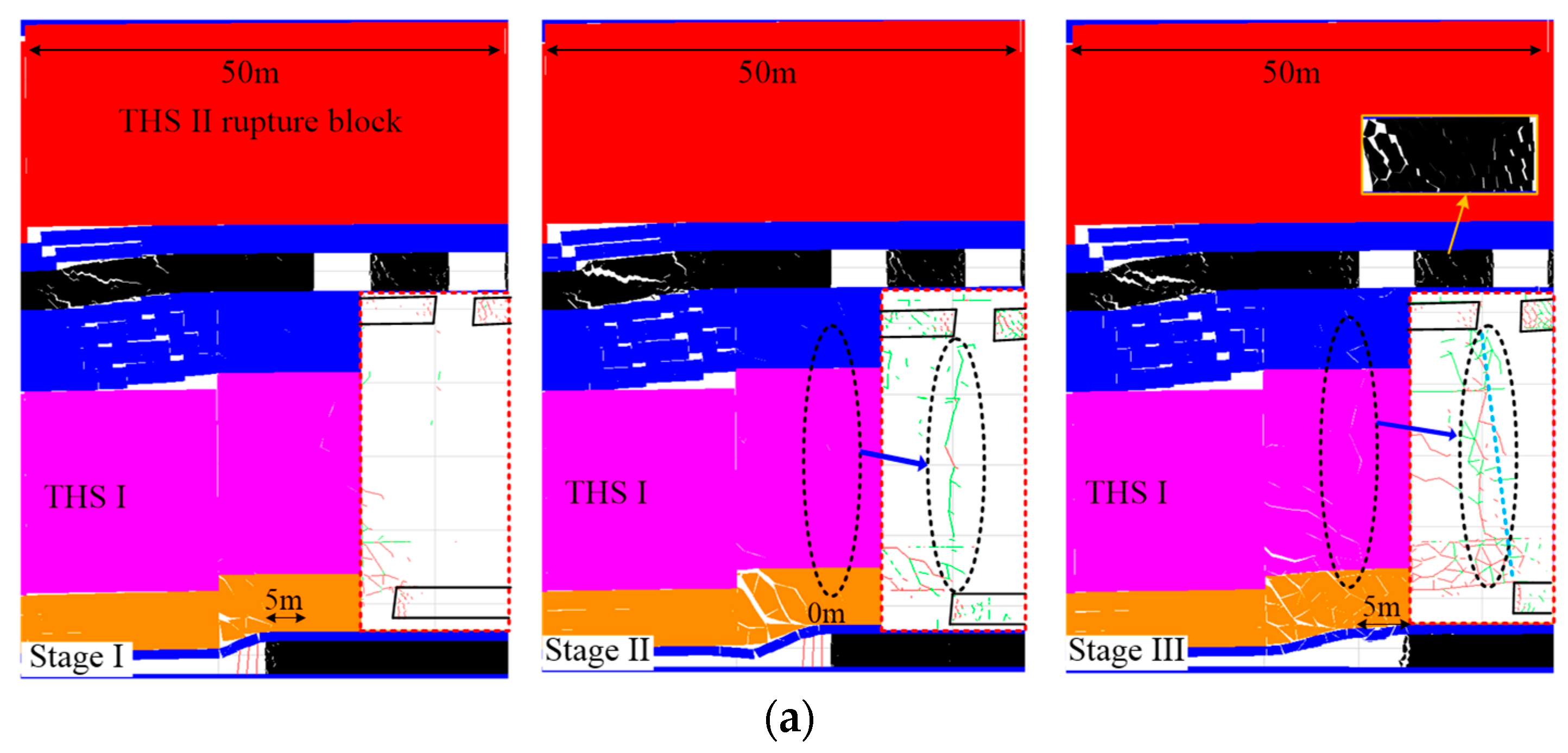
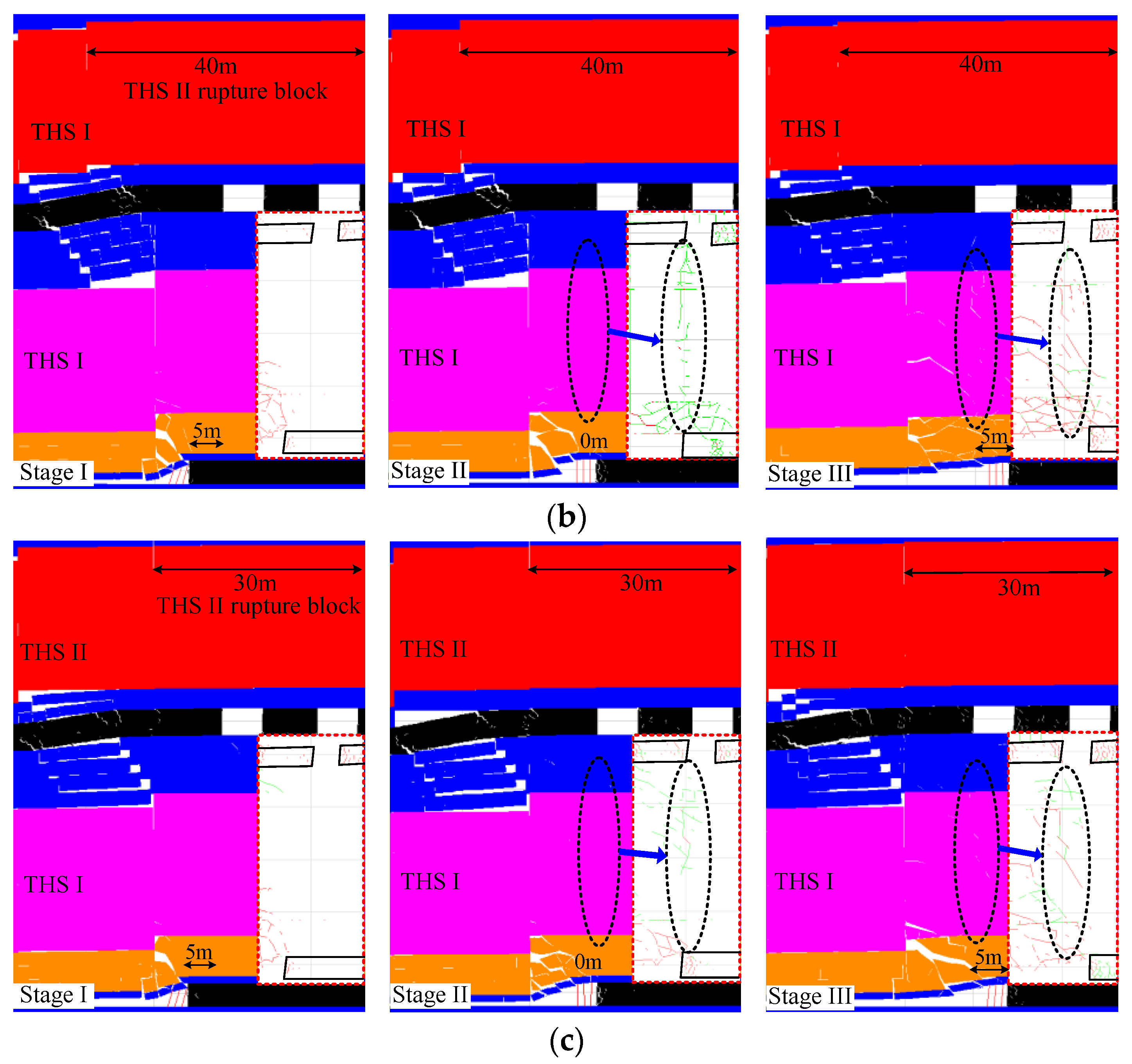
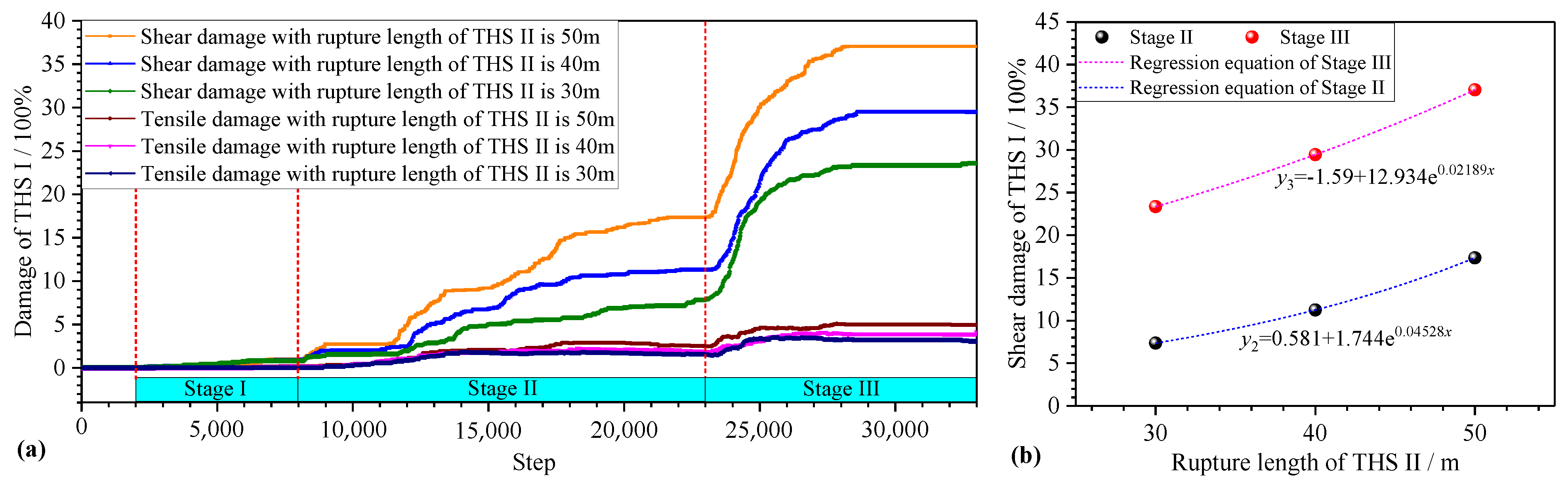
4.2. Failure Characteristics of THS I

Figure 8 and Figure 9 illustrate the shear characteristics and damage of THS I with different THS II rupture lengths (the red lines in Figure 8 indicate the tensile cracks and the green lines indicate the shear cracks). Stage I: the working face is 5 m in front of the residual pillar boundary; Stage II: the working face is below the boundary of the residual pillar; and Stage III: the working face is 5 m away from the boundary of the coal pillar.
According to the simulation results, when the rupture length of THS II was 50 m, tiny cracks began to appear in THS I during Stage I, and the shear damage reached 1%. During Stage II, the shear failure of THS I became more apparent, producing a large number of shear cracks and a small number of tensile fractures. The shear damage also increased to 17.4% (Figure 10), and a continuous shear fracture was formed along the edge of the residual barrier pillar. In Stage III, the load transmitted by the barrier pillar caused shear failure in THS I. The shear damage further increased to 37%, and the shear fractures in THS I further expanded, ultimately forming macroscopic opening fractures with a slip surface angle of about 75°. These results greatly increase the risk of support-crushing accidents (Figure 9a).
When the rupture length of THS II was 40 m, the shear damage of THS I during Stage I and Stage II was 0.87% and 11.25%, respectively (Figure 10). A small number of shear cracks appeared during Stage II but did not coalesce. In Stage III, THS I underwent shear failure, and the shear damage reached 29.43%. The THS I shear slid along the edge of the barrier pillar to the roof of the 3-1 coal seam and formed a macroscopic sliding surface, which is also prone to support-crushing accidents (Figure 9b).
When the rupture length of THS II was 20 m, the shear damage of THS I during the three different stages was 0.84%, 7.83%, and 23.59%, respectively (Figure 10). During Stage III, only a few scattered shear cracks appeared in THS I, but there was no obvious macroscopic sliding surface formed. The damage to the lower working face was minimal, making it less prone to support-crushing accidents (Figure 9c).
As shown in Figure 10, the shear damage of THS I is much greater than the tensile damage, and shear cracks played a predominant role in the failure of THS I. The room-and-pillar mining of the upper 2-2 coal seam has little effect on the damage of THS I. During Stage I, the damage was not significant, whereas it gradually increased during Stage II. In Stage III, the damage increased rapidly to its maximum value (Figure 10a). The regression models of shear damage for THS I are presented in Figure 10b. It can be seen that as the rupture length of THS II increases, the shear damage of THS I increases exponentially during Stage II and Stage III. Evidently, for MWFRPs, the longer the rupture length of THS II, the more severe the shear damage of THS I and the greater risk of support-crushing accidents. Therefore, it is recommended to adopt artificial roof-cutting technologies to reduce the rupture length of THS II.

5. Hydraulic Roof-Cutting Control Technology

5.1. Hydraulic Roof Cutting Scheme

Based on the aforementioned study, for MWFRPs, the superimposed rotational movement of the THS II long-hanging roof and the internal concentrated stress of the residual pillar affect the appearance of mining pressure in the 31106 working face. Therefore, hydraulic roof-cutting technology was proposed for the working face being mined for the next 40 m of residual pillars to reduce the length of the hanging roof formed by the THS II rupture and alleviate the pressure on the working face. The primary target of hydraulic roof cutting is a THS I with a thickness of 21.4 m and a THS II with a thickness of 21.8 m above the 3-1 and 2-2 coal seams, respectively. The arrangement of the hydraulic roof-cutting drill holes is presented in Figure 11. Ten drill holes were symmetrically arranged in the headgate and tailgate of the 31106 working face. The drill holes in the tailgate were numbered B1–B5, and those in the headgate were numbered B6–B10. The spacing between the drill holes within the same group was 2 m, with the first drill hole (B1 and B6) located 6 m in front of the residual pillar boundary. The drilling direction was perpendicular to the axis direction of the roadway. The depths of the boreholes of B1–B5 were 73 m, 101 m, 120 m, 83 m, and 121 m, with inclination angles of 65, 40, 27, 52, and 33°, respectively.

5.2. Hydraulic Roof-Cutting Control Effect

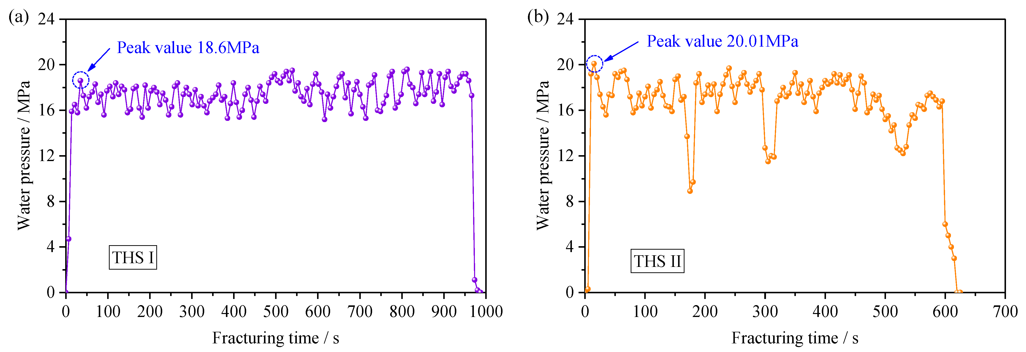
5.2.1. Hydraulic Fracturing Water Pressure

Figure 12 displays the hydraulic fracturing water pressure data. It can be found that the peak rock fracturing pressures at THS I and THS II were 18.6 MPa and 20.01 MPa, respectively. When the water pump started, high-pressure water filled the pipeline with low pressure in the 0–8 s range. From 20–30 s, the pressure reached its peak value, indicating that the rock was fractured. After the rock was fractured, the pressure decreased by about 2–4 MPa and then stabilized in the range of 16–18 MPa. During this time, the fractures inside the rock continued to expand under the action of high-pressure water. The fracturing duration of THS I and THS II was 660 s and 1000 s, respectively.

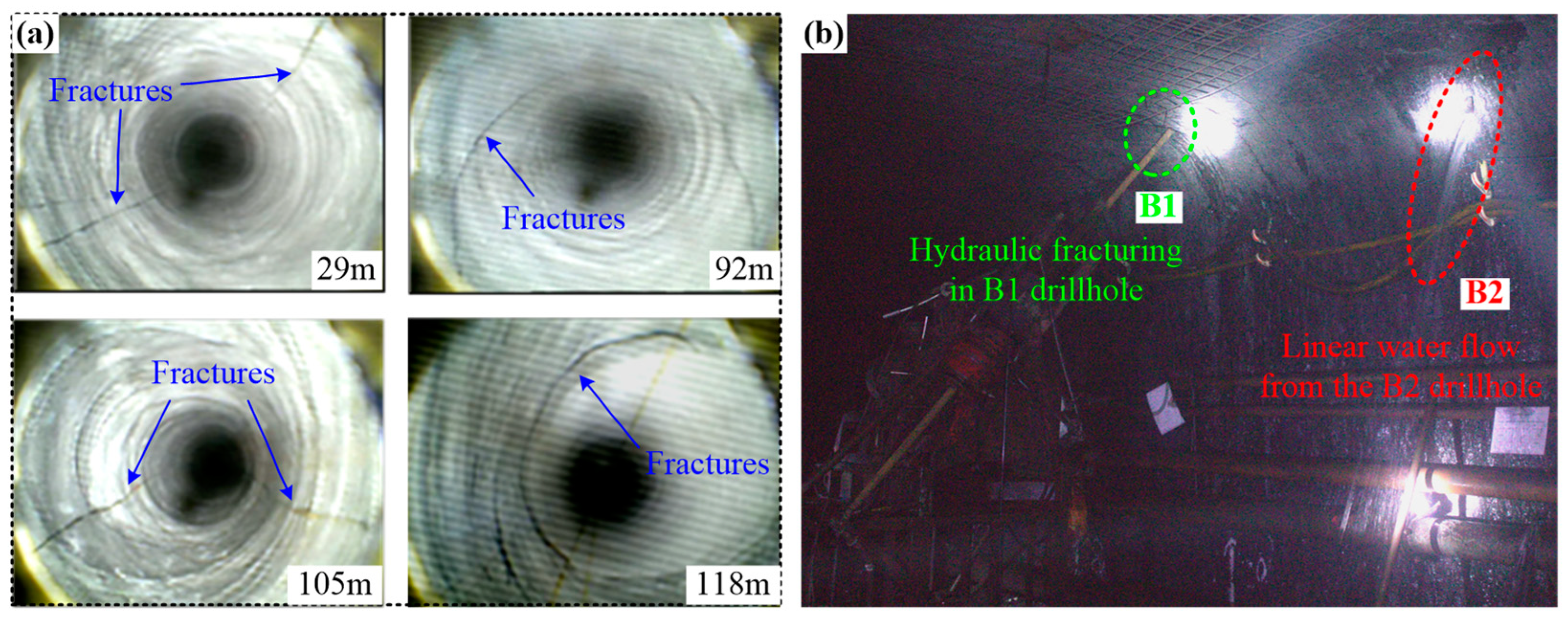
5.2.2. Borehole Camera Exploration for Hydraulic Fractures

A DC-10 borehole camera exploration device was used to monitor the hydraulic fractures after fracturing, as shown in Figure 13. The equipment consists of a host, camera, optical fiber, battery, and transmission rod (Figure 13a). The camera is composed of a front camera and a side camera (Figure 13b). The front camera is mainly used to observe the distribution and morphology of fractures on the borehole wall, and the image is displayed on the large screen of the host. The side camera is equipped with a high-magnification zoom device, which is used to assist the front camera in accurately identifying hydraulic fractures. The image is displayed on a dedicated external small screen (Figure 13c). Then, the camera probe is inserted into the borehole slowly with the transfer rod. The transfer rod can be used to record the location of the camera probe and the failure patterns at different depths. The working principle of the borehole camera is to convert the images captured by the camera into electronic signals through optical fibers and display the images on the screen. It not only has the advantages of convenient portability but also can accurately observe the length and expansion direction of fractures.
The morphology of the fractures on the borehole walls was obtained by using a borehole camera after hydraulic fracturing, as shown in Figure 14. The fractures appeared on the borehole walls at different depths (Figure 14a). In particular, there are several fine cracks within a depth of 29 m, and depths ranging from 92–118 m correspond to the positions of THS I and THS II, respectively. It can be observed from Figure 14b that when high-pressure water was injected in borehole B1, water flowed out from borehole B2, indicating that the radius of the expanded fractures exceeded 10 m. Hydraulic fracturing roof cutting can effectively destroy the integrity of the thick hard strata and promote their collapse.

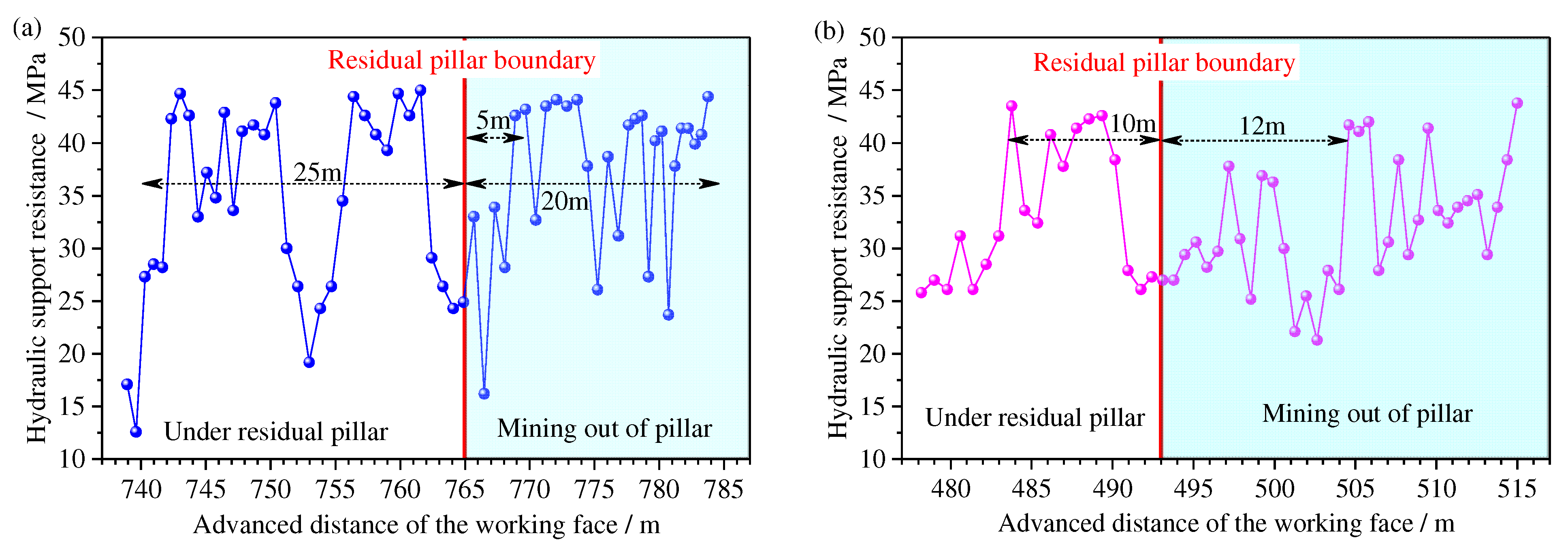
5.2.3. Working Resistance of Hydraulic Support

The hydraulic support working resistance curve before and after hydraulic fracturing for MWFRPs is shown in Figure 15. Before the hydraulic roof cutting, the support resistance was relatively high (within the range of 25 m) in front of the residual pillar boundary, with an average value of 45 MPa. After the working face mining of the pillar boundary of 5 m, the support resistance increased, resulting in a continuous length of 15 m, and coal-wall spalling appeared on-site (Figure 15a). After hydraulic roof cutting, THS II was ruptured above the residual barrier pillar, and the support resistance was relatively low, with an average value of 41 MPa within 10 m of the front of the pillar boundary. There were no strong mining pressure appearances within a range of 12 m after the working face moved away from the residual pillar boundary, and the support pressure was all less than 40 MPa (Figure 15b). Evidently, the hydraulic roof-cutting control technology effectively reduces the strong dynamic load borne by the hydraulic support.

6. Discussion

Hydraulic fracturing (HF) technology was initiated in the oil industry and is now being used in the cave mining industry as a preconditioning method and to enhance gas drainage and roof rock cave-ins in underground coal mines, as listed in Table 3. In the United States, HF has also been successfully applied to stimulating the release of entrapped hydrocarbons from unconventional (i.e., shale or carbonate) formations in shale oil and gas fields [45]. HF and directional hydraulic fracturing (DHF) have been widely applied to induce cave-ins in conglomerate roof rock behind a longwall face and to precondition a conglomerate roof ahead of mining. Preconditioning is undertaken to allow cave-ins to occur soon after longwall startup to avoid a windblast hazard. In this paper, HF, as a preconditioning method, was used to destroy the integrity of thick and hard strata and release stress in MWFRPs in the Huoluowan Coal Mine, China. Field practice has proved that hydraulic fracturing roof cutting produces good results. However, DHF can be used to control the propagation direction of hydraulic fractures by grooving specified rock formations [36]. Another method is to construct directional drilling according to the position of hard rock and then use hydraulic fracturing [40,46,47]. In future studies, the directional hydraulic fracturing scheme for roofs above residual coal pillars should be studied, and the control effect of HF and DHF on strong mining pressures should be comparatively analyzed.

7. Conclusions

A physical model and numerical simulation were combined to investigate the appearance of strong mining pressures in the 31106 working face under residual pillars (MWFRPs), and a hydraulic fracturing roof-cutting technology was proposed. We draw the following conclusions:
(1)
For MWFRPs, the distribution of hydraulic support resistance within the range of 40–45 MPa increases to 66.7%, and the safety valve opening rate increases to 31.2% (the safety valve opening pressure is 43 MPa). Therefore, the appearance of strong mining pressures in MWFRPs can easily cause hydraulic support-crushing accidents.
(2)
During the mining period of MWFRPs, the instability of overlying residual pillars caused the upper thick hard strata (THS II) to rupture and form a “T-shaped structure”. The rotation and sinking deformation of the structure lead to the dynamic load being transmitted downwards, leading to the shear failure in lower thick strata (THS I) along the boundary of the residual pillar. This led to a 70.4% increase in mining pressure in the working face, resulting in the appearance of strong mining pressures.
(3)
The numerical simulation shows that the shear damage of THS I corresponding to a fracture length of 50 m, 40 m, and 30 m in THS II was 37, 29.43, and 23.59%, respectively. During the mining period of MWFRPs, the smaller the length of the THS II fracture block, the smaller the shear damage of THS I, and the lower the mining pressure in the working face.
(4)
A hydraulic fracturing roof-cutting pressure-relief technology was proposed to destroy the integrity of THS I and THS I in MWFRPs. The field applications show that THS II ruptured above the residual pillar. All the support pressures were less than 40 MPa, which means that the strong dynamic load borne by the hydraulic support was reduced, proving the effectiveness of the hydraulic roof-cutting control technology.
In this study, a hydraulic fracturing cutting technology was used in the Huoluowan coal mine, and successful outcomes from industrial tests were obtained. This research provides a reference for safe mining at working faces under similar conditions. However, this research presents the application of hydro-fracturing at the field scale. The influence of concentrated stress from the pillars, natural fractures, rock strata interfaces, etc. on hydraulic fracturing propagation should be further investigated on the basis of this research.

Author Contributions

Conceptualization, X.W. and W.W.; methodology, W.W.; software, X.Y.; validation, G.F. and W.W.; formal analysis, X.Y.; investigation, W.W.; resources, J.B.; data curation, X.Z.; writing—original draft preparation, W.W.; writing—review and editing, X.Y.; visualization, X.Y.; supervision, G.F.; project administration, G.F. and J.B.; funding acquisition, W.W., J.B. and G.F. All authors have read and agreed to the published version of the manuscript.

Funding

This research has been supported by the National Natural Science Foundation of China (Grant No. 52204150, U21A20107), Fundamental Research Program of Shanxi Province (202103021223051), Youth Foundation of TYUT (2022QN069), Science and Technology Innovation Program Project of Higher Education Institutions in Shanxi Province (2021L065) and Tencent Foundation or XPLORER PRIZE.

Acknowledgments

The authors thank Huoluowan coal mine for their support during the field test.

Conflicts of Interest

The authors declare no conflict of interest.

Correction Statement

This article has been republished with a minor correction to the readability of Figure 1. This change does not affect the scientific content of the article.

References

  1. Zhang, Y.Q.; Wang, X.Y.; Zhang, F.T.; Li, M.L.; Wang, G.H.; Chen, D.C.; Li, G.J.; Zhao, X.Q. Retracement ground pressure appearance and control of the working face under the overlying residual pillar: A case study. Energies 2023, 16, 1701. [Google Scholar] [CrossRef]
  2. Zhu, D.F.; Tu, S.H.; Tu, H.S.; Yang, Z.Q. Mechanisms of support failure and prevention measures under double-layer room mining gobs—A case study: Shigetai coal mine. Int. J. Min. Sci. Technol. 2019, 29, 955–962. [Google Scholar] [CrossRef]
  3. Liu, H.F.; Sun, Q.; Zhou, N.; Wu, Z.Y. Risk Assessment and control strategy of residual coal pillar in room mining: Case study in ecologically fragile mining areas, China. Sustainability 2021, 13, 2712. [Google Scholar] [CrossRef]
  4. Ju, J.F.; Xu, J.L.; Zhu, W.B.; Liu, K. Influence of cut-hole position on support crushing during mining out coal pillar at the side of upper goaf in close distance of shallow seams. Chin. J. Rock Mech. Eng. 2014, 33, 2018–2029. [Google Scholar]
  5. Wu, W.D.; Bai, J.B.; Wang, X.Y.; Zhu, Z.J.; Yan, S. Field investigation of fractures evolution in overlying strata caused by extraction of the jurassic and carboniferous coal seams and its application: Case study. Int. J. Coal Geol. 2019, 208, 12–23. [Google Scholar] [CrossRef]
  6. Bai, J.W.; Song, C.; Wang, H.W.; Qi, T.Y.; Feng, G.R.; Cao, G.M.; Wang, K.; Guo, J.; Shi, X.D.; Cui, B.Q. Identification method and software of key pillar in the residual pillar system. J. China Coal Soc. 2022, 47, 651–661. [Google Scholar]
  7. Liang, Y.P.; Li, B.; Zou, Q.L. Movement type of the first subordinate key stratum and its influence on strata behavior in the fully mechanized face with large mining height. Arab. J. Geosci. 2019, 12, 12–31. [Google Scholar] [CrossRef]
  8. Bosikov, I.I.; Martyushev, N.V.; Klyuev, R.V.; Savchenko, I.A.; Kukartsev, V.V.; Kukartsev, V.A.; Tynchenko, Y.A. Modeling and complex analysis of the topology parameters of ventilation networks when ensuring fire safety while developing coal and gas deposits. Fire 2023, 6, 95. [Google Scholar] [CrossRef]
  9. Balovtsev, S.V.; Skopintseva, O.V.; Kolikov, K.S. Aerological risk management in preparation for mining of coal mines. Sustain. Dev. Mt. Territ. 2022, 14, 107–116. [Google Scholar] [CrossRef]
  10. Zhu, W.B.; Xu, J.M.; Li, Y.C. Mechanism of the dynamic pressure caused by the instability of upper chamber coal pillars in Shendong coalfield, China. Geosci. J. 2017, 21, 1–13. [Google Scholar] [CrossRef]
  11. Xu, J.M.; Zhu, W.B.; Ju, J.F. Mechanism of dynamic mine pressure occurring below adjacent upper chamber mining goaf with shallow cover depth. J. China Coal Soc. 2017, 42, 500–509. [Google Scholar]
  12. Zhu, W.B.; Chen, L.; Zhou, Z.L.; Shen, B.T.; Xu, Y. Failure propagation of pillars and roof in a room and pillar mine induced by longwall mining in the lower seam. Rock Mech. Rock Eng. 2019, 52, 1193–1209. [Google Scholar] [CrossRef]
  13. Wang, F.T.; Zhang, C. Reasonable coal pillar design and remote control mining technology for highwall residual coal resources. Roy. Soc. Open Sci. 2019, 6, 181817. [Google Scholar] [CrossRef] [PubMed] [Green Version]
  14. Guo, F.; Gao, B.; Niu, G.Q.; Wang, Z.G. Study on mine strata pressure law of fully mechanized coal mining face under coal pillars and goaf in contiguous seams. Coal Sci. Technol. 2017, 45, 92–97. [Google Scholar]
  15. Zhou, K.Y.; Zhang, H.W.; Li, Y.P.; Fu, X.; Cao, Y. Study on the zoning characteristics of strata behaviors during the primary mining of mining face under contiguous goaf. Coal Sci. Technol. 2018, 46, 54–60. [Google Scholar]
  16. Huo, B.J.; Jing, X.D.; Fan, Z.L.; Xie, W.; Duan, Z.H.; Xie, Z.H. Mechanism of dynamic load of longwall mining under shallow room mining goaf. China J. Geo. Eng. 2019, 41, 1116–1123. [Google Scholar]
  17. Tian, C.L.; Yang, X.L.; Sun, H.T.; Liu, Y.B.; Hu, Q.T. Experimental study on the overburden movement and stress evolution in multi-seam mining with residual pillars. Energy Sci. Eng. 2019, 7, 3095–3110. [Google Scholar] [CrossRef] [Green Version]
  18. Fu, X.Y.; Li, H.Y.; Li, F.M.; Li, S.G.; Zhang, B.; Li, H.J.; Wei, L.K. Mechanism and prevention of strong strata behaviors induced by the concentration coal pillar of a room mining goaf. J. China Coal Soc. 2016, 41, 1375–1383. [Google Scholar]
  19. Poulsen, B.A. Coal pillar load calculation by pressure arch theory and near field extraction ratio. Int. J. Rock Mech. Min. Sci. 2010, 47, 1158–1165. [Google Scholar] [CrossRef]
  20. Zhang, C.; Zhao, Y.X.; Han, P.H.; Bai, Q.S. Coal pillar failure analysis and instability evaluation methods: A short review and prospect. Eng. Fail. Anal. 2022, 138, 106344. [Google Scholar] [CrossRef]
  21. Wu, W.D.; Bai, J.B.; Wang, X.Y.; Yan, S.; Wu, S.X. Numerical study of failure mechanisms and control techniques for a gob-side yield pillar in the Sijiazhuang coal mine, China. Rock Mech. Rock Eng. 2019, 52, 1231–1245. [Google Scholar] [CrossRef]
  22. Esterhuizen, G.S.; Tyrna, P.L.; Murphy, M.M. A case study of the collapse of slender pillars affected by through-going discontinuities at a limestone mine in Pennsylvania. Rock Mech. Rock Eng. 2019, 52, 4941–4952. [Google Scholar] [CrossRef] [PubMed]
  23. Tian, Y.; Gong, P.L.; Zhao, T.; Yi, K.; Wen, G. Instability prediction model of remaining coal pillars under remining disturbance. Energy Sci. Eng. 2023, 1–16. [Google Scholar] [CrossRef]
  24. Hashiba, K.; Fukui, K. Time—Dependent behaviors of granite: Loading-rate dependence, creep, and relaxation. Rock Mech. Rock Eng. 2016, 49, 2569–2580. [Google Scholar] [CrossRef]
  25. Zhou, Z.L.; Chen, L.; Cai, X.; Shen, B.T.; Zhou, J.; Du, K. Experimental investigation of the progressive failure of multiple pillar-roof system. Rock Mech. Rock Eng. 2018, 51, 1629–1636. [Google Scholar] [CrossRef]
  26. Zhou, Z.L.; Zang, H.Z.; Cao, W.Z.; Du, X.M.; Chen, L.; Ke, C.T. Risk assessment for the cascading failure of underground pillar sections considering interaction between pillars. Int. J. Rock Mech. Min. Sci. 2019, 124, 104142. [Google Scholar] [CrossRef]
  27. Dong, H.Y.; Zhu, W.C.; Hou, C.; Liu, X.G. Load transfer behavior during cascading pillar failure: An experimental study. Rock Mech. Rock Eng. 2022, 55, 1445–1460. [Google Scholar] [CrossRef]
  28. Meng, N.K.; Chen, Y.; Bai, J.B.; Wang, X.Y.; Wu, W.D.; Wu, B.W. Numerical simulation of directional fracturing by shaped charge blasting. Energy Sci. Eng. 2020, 8, 1824–1839. [Google Scholar] [CrossRef]
  29. Zhou, N.; Yan, H.; Jiang, S.Y.; Sun, Q.; Ouyang, S.Y. Stability Analysis of Surrounding Rock in Paste Backfill Recovery of Residual Room Pillars. Sustainability 2019, 11, 478. [Google Scholar] [CrossRef] [Green Version]
  30. Miao, K.J.; Wang, D.P.; Tu, S.H.; Tu, H.S.; Zhu, D.F.; Liu, X.W.; Li, W.L.; Tang, L. The principle and practice of strong mine pressure control in the initial mining and caving stages under multiple key strata. Sustainability 2022, 14, 5772. [Google Scholar] [CrossRef]
  31. Li, Y.; Yang, T.H.; Hao, N.; Song, W.D.; Fu, J.X.; Yu, L. Mining rate effect of high-intensity working face based on stress release rate and microseismic monitoring. J. Min. Saf. Eng. 2022, 38, 295–303. [Google Scholar]
  32. Dehghan, A.N. An experimental investigation into the influence of pre-existing natural fracture on the behavior and length of propagating hydraulic fracture. Eng. Fract. Mech. 2020, 24, 107330. [Google Scholar] [CrossRef]
  33. Huang, B.X.; Wang, Y.Z.; Cao, S.G. Cavability control by hydraulic fracturing for top coal caving in hard thick coal seams. Int. J. Rock Mech. Min. Sci. 2015, 74, 45–57. [Google Scholar] [CrossRef]
  34. Chang, Q.L.; Yao, X.J.; Wang, X.Y.; Yang, S.; Sun, Y.T. Investigation on hydraulic fracturing and cutting roof Pressure relief technology for underground mines: A case study. Lithosphere 2021, 2021, 4277645. [Google Scholar] [CrossRef]
  35. Jeffrey, R.G.; Mills, K.W. Hydraulic fracturing applied to inducing longwall coal mine goaf falls. In Proceedings of the 4th North American Rock Mechanics Symposium, Seattle, WA, USA, 31 July–3 August 2000; pp. 423–430. [Google Scholar]
  36. Klishin, V.; Opruk, G.; Ponizov, A. Directional hydraulic fracturing application for reduction of rock heaving intensity in the development opening under conditions of S.M. Kirov Mine. In Proceedings of the Russian-Chinese Symposium on Coal in the 21st century, Qingdao, China, 18–21 October 2018. [Google Scholar]
  37. Jendry, M.; Hadam, A.; Wikaa, M. Directional hydraulic fracturing (DHF) of the roof, as an element of rock burst prevention in the light of underground observations and numerical modelling. Energies 2021, 14, 562. [Google Scholar] [CrossRef]
  38. He, Q.Y.; Suorineni, F.T.; Oh, J. Strategies for creating prescribed hydraulic fractures in cave mining. Rock Mech. Rock Eng. 2017, 50, 967–993. [Google Scholar] [CrossRef]
  39. Zhang, F.T.; Wang, X.Y.; Bai, J.B.; Wu, W.D.; Wu, B.W.; Wang, G.H. Fixed-length roof cutting with vertical hydraulic fracture based on the stress shadow effect: A case study. Int. J. Min. Sci. Technol. 2022, 32, 295–308. [Google Scholar] [CrossRef]
  40. Liu, W.J.; Yang, K.; He, X.; Zhang, Z.N.; Xu, R.J. Mechanism and control technology of rockburst induced by thick hard roof and residual coal pillar: A case study. Geofluids 2023, 2023, 3523592. [Google Scholar] [CrossRef]
  41. Gao, R.; Kuang, T.J.; Zhang, Y.Q.; Zhang, W.Y.; Quan, C.Y. Controlling mine pressure by subjecting high-level hard rock strata to ground fracturing. Int. J. Coal Sci. Technol. 2021, 8, 1336–1350. [Google Scholar] [CrossRef]
  42. Yang, S.; Li, X.H.; Wang, J.; Yang, S.H.; Shen, Z.; Xu, G.Z. Study on pressure relief technology of high-pressure water jet of residual coal pillar in overlying goaf in close seam mining. Shock Vib. 2022, 2022, 7842921. [Google Scholar] [CrossRef]
  43. Kang, H.P.; Si, L.P.; Zhang, X. Characteristics of underground in-situ stress distribution in shallow coal mines and its applications. J. China Coal Soc. 2016, 41, 1332–1340. [Google Scholar]
  44. Gao, F.Q. Simulation of Failure Mechanisms around Underground Coal Mine Openings Using Discrete Element Modelling. Ph.D. Thesis, Simon Fraster University, Burnaby, BC, Canada, 2013. [Google Scholar]
  45. Coonrod, C.L.; Yin, Y.B.; Hanna, T.; Atkinson, A.J.; Wong, M.S. Fit-for-purpose treatment goals for produced waters in shale oil and gas fields. Water Res. 2020, 173, 115467. [Google Scholar] [CrossRef] [PubMed]
  46. Lekontsev, Y.M.; Sazhin, P.V.; Ushakov, S.Y. Interval hydraulic fracturing to weaken dirt bands in coal. J. Min. Sci. 2013, 48, 525–532. [Google Scholar] [CrossRef]
  47. Lekontsev, Y.M.; Sazhin, P.V. Directional hydraulic fracturing in difficult caving roof control and coal degassing. J. Min. Sci. 2014, 50, 525–532. [Google Scholar] [CrossRef]
  48. Subrahmanyam, D.S.; Shyam, G.; Vamshidhar, K.; Vikram, S. State-of-the-art technique to conduct in situ stress measurements in deep proposed coal-mining blocks of Singareni collieries, India. Curr. Sci. India 2020, 119, 1027–1030. [Google Scholar] [CrossRef]
  49. Cheng, Q.Y.; Huang, B.X.; Shao, L.Y.; Chen, S.L.; Li, H.Z.; Wang, C.W. Combination of pre-pulse and constant pumping rate hydraulic fracturing for weakening hard coal and rock mass. Energies 2020, 13, 5534. [Google Scholar] [CrossRef]
  50. Mahdavian, D.; Javadi, A. Study of hydraulic fracturing for gas drainage in a coal mine in Iran. Environ. Geotech. 2022, 8, 547–558. [Google Scholar] [CrossRef]
Figure 1. Layout of the No. 31106 longwall panel. (a) Mine location. (b) Panel layout. (c) Generalized stratigraphy column. (d) The 2-2 coal seam residual coal pillars.
Energies 16 03914 g001
Figure 2. Contour of hydraulic support resistance during the 31106 working face mining under a residual pillar.
Energies 16 03914 g002
Figure 3. Physical model and monitoring plans.
Energies 16 03914 g003
Figure 4. Characteristics of overlying strata fracture. (a) Stage I. (b) Stage II. (c) Stage III.
Energies 16 03914 g004
Figure 5. Stress curve of the 3-1 coal seam roof.
Energies 16 03914 g005
Figure 6. Vertical displacement curve of the overlying strata.
Energies 16 03914 g006
Figure 7. Two-dimensional numerical model.
Energies 16 03914 g007
Figure 8. The calibrated stress-strain curves obtained from UCS using the UDEC Trigon model.
Energies 16 03914 g008
Figure 9. Shear characteristics of THS I with different THS II rupture lengths. (a) Rupture length of THS II is 50 m; (b) Rupture length of THS II is 40 m; (c) Rupture length of THS II is 30 m.
Energies 16 03914 g009aEnergies 16 03914 g009b
Figure 10. Damage to THS I with different THS II rupture lengths. (a) Damage of THS I for MWFRPs; (b) Regression models of shear damage for THS I.
Energies 16 03914 g010
Figure 11. Drillhole layout scheme for hydraulic fracturing in the region of the residual pillars.
Energies 16 03914 g011
Figure 12. Curve of hydraulic fracturing water pressure vs. time. (a) THS I; (b) THS II.
Energies 16 03914 g012
Figure 13. The DC-10 borehole camera exploration device. (a) Major structure of the device. (b) Front and side camera. (c) Fractures observed.
Energies 16 03914 g013
Figure 14. Borehole camera exploration results. (a) Fracture morphology. (b) Construction in the field.
Energies 16 03914 g014
Figure 15. Curve of hydraulic support resistance before and after hydraulic fracturing. (a) Before hydraulic fracturing. (b) After hydraulic fracturing.
Energies 16 03914 g015
Table 1. Proportioning parameters of rock strata in the physical model.
Bed No.LithologyThickness
(cm)
Matching
Number
Gross Weight
(kg)
Sand
(kg)
CaCO3
(kg)
Gypsum
(kg)
Water
(L)
22Loess layer877374.8065.456.552.818.31
21Medium-grained sandstone537346.7535.068.183.515.19
20Siltstone11455102.8582.2810.2910.2911.43
19Sandy mudstone12637112.2096.174.8111.2212.47
18Medium-grained sandstone14373130.9098.1822.919.8214.54
17Sandy mudstone663756.1048.092.405.616.23
16Medium-grained sandstone12373112.2084.1519.648.4212.47
15Fine sandstone12355112.2084.1514.0314.0312.47
14Medium-grained sandstone737365.4549.0911.454.917.27
13Sandy mudstone563746.7540.072.004.685.19
12Fine sandstone11355102.8577.1412.8612.8611.43
11Medium-grained sandstone337328.0521.044.912.103.12
10Siltstone445537.4029.923.743.744.16
9Fine sandstone22437205.70164.5612.3428.8022.86
8Mudstone355528.0523.382.342.343.12
7No. 2-2 coal557346.7538.965.452.345.19
6Mudstone855574.8062.336.236.238.31
5Fine sandstone21355196.35147.2624.5424.5421.82
4Siltstone645556.1044.885.615.616.23
3Mudstone15559.357.790.780.781.04
2No. 3-1 coal457337.4031.174.361.874.16
1Sandy mudstone1063793.5080.144.019.3510.39
Table 2. Properties of blocks and joints in the numerical model.
Rock StrataBlock PropertiesJoint Properties
Density
(kg/m3)
E
(GPa)
Poisson’s RatioKn
(GPa/m)
Ks
(GPa/m)
Cohesion
(MPa)
Friction Angle
(°)
Tensile Strength
(MPa)
THS II23582.880.2937.7315.094.65324.00
THS I22812.130.2525.6010.243.82293.59
Siltstone22671.600.2619.627.853.31233.27
Sandy mudstone21820.950.2812.124.852.49202.79
Coal seam12630.310.2611.514.591.55171.92
Table 3. Application case statistics for hydraulic fracturing technology.
No.TechnologyCoal MinePurposeRegionReference
1Hydraulic fracturingMoonee CollieryInducing a goaf event and controlling the timing of caving eventsAustralia[35]
2Singareni collieriesIn-situ stress measurementIndia[48]
4Bailu Coal MineWeakening hard coal and rock massChina[49]
Parvadeh 4 coal mineGas drainageIran[50]
5Yanzishan coal mineWeakening and relieving stressChina[42]
6Shale oil and
gas fields
Stimulating the release of entrapped hydrocarbons from formationsUSA[45]
7gas fieldsRoof PressureChina[34]
8Directional hydraulic fracturingS.M. Kirov MineReducing rock-heaving intensity in the development openingRussian[36]
9Romanovsky MineWeakening a dirt band in Abramovsky coal seamRussian[46]
10Kuzbass Coal MineCaving roof control in production faces and coal bed degassingRussian[47]
11“Rydultowy” Black Coal MineRock burst preventionPoland[37]
12Boertai Coal MineBlock caving and rock burst preventionChina[40]
Disclaimer/Publisher’s Note: The statements, opinions and data contained in all publications are solely those of the individual author(s) and contributor(s) and not of MDPI and/or the editor(s). MDPI and/or the editor(s) disclaim responsibility for any injury to people or property resulting from any ideas, methods, instructions or products referred to in the content.

