Abstract
Background and Purpose: The stator vibration characteristics are comprehensively mastered by considering the influence of winding and the housing structure on the stator modes. This effect is neglected in the research field of electromagnetic vibration of permanent magnet synchronous motors (PMSMs). Methods: The radial air-gap flux density equations and PMSM’s electromagnetic force density are derived, and then the harmonic characteristics of electromagnetic force density are studied. An equivalent finite element model of the stator is proposed that investigates the impacts of the winding and stator housing rules on the stator modal frequency. Finally, the harmonic response and acoustic analyses of electromagnetic vibration are carried out based on multi-physics field coupling. Results: The equivalent radiated power distribution laws and acoustic field of motor electromagnetic vibration under transient operating conditions are obtained. The theoretical analysis results are consistent with the experimental results. Conclusion: The obtained results show that the spatial order of the radial electromagnetic force is not equal to the order of the radial mode of the motor stator. The reason for this is that structural resonance is induced when the frequency components of the spatial radial electromagnetic force are coupled with the intrinsic frequency of the stator.
1. Introduction
A permanent magnet synchronous motor (PMSM) has various advantages (small volume, lightweight, low loss, high efficiency, reliable operation, etc.) [1]. They can be designed to operate over a wide torque-speed range with superior torque density and power density [2], and have been widely used in industrial and agricultural production [3]. However, the complex rotor structure of the PMSM leads to a large amount of torque ripple and rich space harmonics, which can cause significant noise and vibration [4]. For this reason, the motors’ noise control capability requirements are much higher than before in certain conditions [5]. Higher vibration severity will aggravate rotor material fatigue and reduce the motor’s lifetime and operational reliability. Thus, research on the vibration and noise of motors has attracted the wide attention of researchers and has become a popular research topic [6].
Electromagnetic noise, as the most prominent factor in the process of motor rotation [7], is induced due to electromagnetic vibration, mechanical vibration, aerodynamics, etc. Therefore, researchers have pointed out that radial electromagnetic force is one of the main factors of electromagnetic vibration [8]. Moreover, [9] found that the electromagnetic force with small harmonic order greatly influences the vibration, and [10] concluded the electromagnetic vibrations are mainly caused by two kinds of magnetic force harmonics whose circumferential spatial order are zero and six. Ref. [11] proposed a method to calculate the magnetic density of the motor air gap, and derived an analytical formula for the electromagnetic force wave, which considered the effect of stator slotting using the magnetic potential multiplied by the magnetic permeability. However, the effect of the motor armature reaction on the magnetic field was ignored. Ref. [12] developed an analytical model for analyzing the radial vibration force, and concluded that the low-order harmonic component of the radial force is mainly due to the interaction between the magnet field and the armature-reaction field, which is largely determined by the combination of the pole and slot numbers.
Ref. [13] calculated the electromagnetic force of an armature-rotating PMSM, and analyzed the influence law of its spatial distribution on motor vibration. The conclusion was that the spatial distribution of the electromagnetic force is not the only decisive factor for the vibration mode shapes. Ref. [14] studied the influence law of the pole slot combination on the electromagnetic vibration and noise of the PMSM, and the results showed that the motor with fractional-slot winding has lower non-zero minimum force wave order and is more prone to resonance. Ref. [15] established the transfer function between the sound field and electromagnetic force and calculated the noise spectrum of the motor under transient conditions. Ref. [16] investigated the electromagnetic vibration characteristics of high-speed (HS) permanent magnet synchronous machines (PMSMs) with amorphous metal stator cores (AMSCs) considering current harmonics.
The existing literature on motor vibration analysis has not considered the influence of the characteristics of winding, the shell, and its composite materials on the stator mode, and thus has not comprehensively evaluated the vibration characteristics of the motor. Moreover, the vibration response of the motor under transient conditions has rarely been reported in recent papers. In this paper, a 65 kW high-power PMSM fan with 36 slots and 12 poles is used. The periodicity of the air-gap flux density, spatiotemporal harmonic components, and electromagnetic force density are analyzed by combining the magnetic potential multiplication method and permeability method with the periodic method. The vibration characteristics of the motor when increasing the speed are studied, and the vibration condition of the motor is analyzed comprehensively.
2. Radial Electromagnetic Force and the Harmonic Characteristics of PMSM
There are currents and magnetic fields in a motor’s circuit and magnetic circuit, and their mutual coupling produces a complex series of forces, which generally include three major categories: Maxwell force, Lorentz force, and magneto strictive force. The Maxwell tension of the iron core is the main part that induces the electromagnetic vibration. Since the amplitude of the radial electromagnetic force on the tip of the stator tooth is much larger than the tangential electromagnetic force, excessive radial electromagnetic force on the tooth tip leads to the circumferential deformation of the stator collar. Therefore, the dominant harmonic content in the electromagnetic force signal will lead to the vibration of the stator and the casing.
2.1. Air-Gap Flux Density
The radial electromagnetic force on the stator teeth is approximately replaced by the electromagnetic force calculated by the air-gap flux density to simplify the solution of the air-gap magnetic field. Neglecting the influence of core reluctance and magnetic saturation, according to [17], the radial flux density of the PMSM can be expressed by Equation (1):
where is the combined air-gap magnetomotive force and is the air-gap ratio permeability.
The air-gap flux density of a permanent magnet motor is determined by the interaction between the permanent magnets and the armature windings. The combined air-gap magnetomotive force can be written as Equation (2):
where is the force of the permanent magnet, is the magnetomotive force of the armature magnetic field. Equation (3) represents the magnetic field magnetomotive force:
where is the harmonic number of the rotor. As the generated magnetic field by the rotor permanent magnet is an odd harmonic function, the harmonic number is . is the subharmonic magnetomotive force amplitude in level , is the number of poles, is the electrical angular frequency, and is the angle difference between the permanent magnet and the winding magnetic potential.
When the excitation current is sinusoidal, the magnetomotive force of the armature magnetic field can be obtained by Equations (4) and (5):
where is the harmonic number of the armature field, is the number of current harmonics, is the amplitude of the -th harmonic magnetomotive force, is the phase angle of times current, , is the number of poles. Considering the slot and rotor salient pole effects, Equation (6) represents the air-gap ratio permeance for built-in motors:
where is the mean value of air-gap specific magnetic conductivity, is the amplitude of the stator tooth harmonic wave, is the amplitude of the rotor tooth harmonic wave, and is the number of stator teeth.
Therefore, the magnetic density of the built-in synthetic air gap can be expressed by Equation (7):
Table 1 shows the air-gap flux density distribution by expanding and analyzing Equation (7), where is the fundamental frequency. In Table 1, the spatial order of the radial air-gap flux density in a built-in PMSM is mainly related to the number of motor poles , the number of stator slots , the number of rotor harmonics , and the number of armature field harmonics . The temporal frequency is impacted by the number of motor poles , the number of rotor harmonics , and the number of current harmonics . Moreover, the spatial order of the air-gap magnetic field increases the component due to the influence of stator slotting t but does not affect time and frequency. Considering the rotor salient pole effect, the component of the air-gap magnetic field spatial order and the component of the temporal frequency increase.

Table 1.
Radial air-gap flux density source, magnitude, spatial order, and temporal frequency.
2.2. Radial Electromagnetic Force Wave
This paper focuses on the spatial order and harmonic frequency of the electromagnetic force wave of the PMSM. In no-load conditions, there is only a magnetic field effect of the permanent magnet in the air gap. Combined with Table 1, the radial air-gap magnetic field under no-load conditions can be expressed by Equation (8):
where is the magnetic density magnitude of the air-gap magnetic field under no-load conditions.
Considering the stator slotting and the rotor salient pole effect, the magnetic field of a permanent magnet and its spatial order have components of , , , and , and the temporal frequency has components of and .
Similarly, the radial air-gap magnetic field of the armature reaction can be approximately written as Equation (9):
where is the magnetic density amplitude of the armature-reaction air-gap magnetic field.
According to the Maxwell stress tensor method, Equation (10) represents the radial electromagnetic force wave:
When the PMSM is under the no-load condition, the radial air-gap flux density can be defined by Equation (11):
Combining Equations (8), (10) and (11), the radial electromagnetic force wave under no-load conditions can be obtained by Equation (12):
Hence, the spatial order of the radial electromagnetic force wave of a built-in PMSM is and the temporal frequency is under no-load conditions.
When the PMSM is under loaded conditions, the radial air-gap flux density can be expressed by Equation (13):
where is the interaction between harmonics of air-gap magnetic field under the no-load condition, is the armature reaction to the interaction between the harmonics of the magnetic field.
The radial electromagnetic force wave in loading conditions can be analyzed from the following aspects:
The interaction between the air-gap magnetic field harmonics produces the radial electromagnetic force wave of the motor under loading conditions, which is expressed by Equation (12). Equation (13) represents the interaction between the armature reaction and air-gap magnetic field harmonics:
Interaction between the air-gap magnetic field and armature-reaction air-gap magnetic field harmonics under no-load conditions can be expressed by Equation (15):
It can be concluded that the spatial order of the radial electromagnetic force wave for a loaded built-in PMSM has three terms: , , and . There are three terms of time and frequency: , , and . Since , , , , , and are odd numbers, the temporal frequency of the load radial electromagnetic force wave needs to be multiplied by , which means the time order is even.
2.3. The Harmonic Characteristics of an Integer-Slot PMSM
For integer-slot motors, is a whole number and can be calculated by . From Equation (8), it can be derived that the magnetic field space order is in the no-load condition. Moreover, considering , and , it can be written that . Therefore, is odd. Furthermore, the space order of the unloaded magnetic field can be expressed as , and the temporal frequency of can be expressed as , . From Equation (9), the space order of the load field is known as , for integer-slot motors of . Considering , , temporal frequency is , , and , . The combined analysis shows that the space order of the air-gap magnetic field in an integer-slot PMSM is , and the temporal frequency is , . For electromagnetic force waves, the space order in a no-load condition is expressed by Equation (16):
Moreover, the space order and the temporal frequency of the electromagnetic force wave for an integer-slotted PMSM are mainly and , , respectively.
For integer-slot motors, the harmonic space order of the rotor permanent magnet magnetic field is , the harmonic space order of the stator winding magnetic field is , and the radial electromagnetic force harmonic space order is . For a 12-pole, 36-slot motor, the lowest order of radial force wave is shown in Table 2. It should be noted that the space order is the minimum value after adding or subtracting .
Table 2.
Space order of radial electromagnetic force and corresponding temporal frequency.
When the PMSM is under the loaded condition, the harmonics generated by the main pole magnetic field of the permanent magnet rotor will interact with the generated first-order and second-order permeability tooth harmonics generated by the armature magnetic field, and the larger electromagnetic force will be induced. The number of first-order tooth harmonics for the motor stator winding is 42, −30, as marked by “ “ in Table 2.
Table 2 shows that the frequency corresponding to the 0th order spatial harmonics is 36 and 72 , in which the 36 frequency is mainly generated by the stator winding first-order tooth harmonic action.
Consequently, there may be a larger amplitude of the radial electromagnetic force density when its frequency is 36 and 72 and its space order is 0.
To verify the correctness of the wave time frequency law of the electromagnetic force of the integer-slot motor based on the above theoretical study of the frequency distribution law of radial electromagnetic force density, the following section uses the transient finite element method to carry out the calculation of the electromagnetic force of the 36-slot 12-pole PMSM at the rated operating speed of 4300 rpm and discusses the results.
3. Electromagnetic Vibration Characteristics of a PMSM under Coupling of Multiple Physical Fields
3.1. Research Method
The flowchart of electromagnetic vibration noise analysis is shown in Figure 1. Firstly, a two-dimensional finite element electromagnetic simulation model is established, and the electromagnetic simulation model with multi-speed scanning is set up. Then, the obtained electromagnetic force results from the simulation are imported into the 3D structural field for magneto-solid coupling analysis. The vibration harmonic response calculations for stator electromagnetic force excitation are carried out to obtain equivalent radiated power (ERP) level waterfall plots. In the next step, the results of the spatial and temporal distributions of electromagnetic force density, the modal analysis of stator structure, and the ERP level diagram are compared and analyzed.
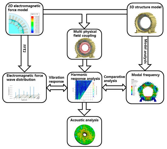
Figure 1.
Flowchart of motor electromagnetic vibration noise calculation.
3.2. Radial Electromagnetic Force Analysis
In Figure 2, a two-dimensional electromagnetic simulation model of a 36-slot, 12-pole PMSM is presented, and its main dimensional structural parameters are shown in Table 3. In this paper, ANSYS Workbench 2022 R1 was used to calculate the electromagnetic force at the rated speed of 4300 rpm by employing the transient finite element method.
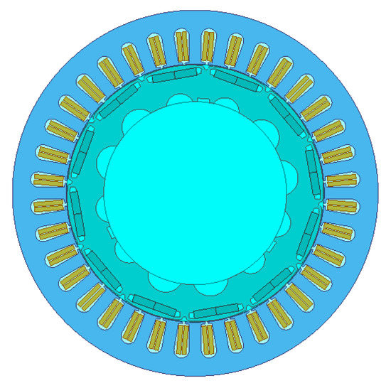
Figure 2.
Two-dimensional structural model of the motor.
Table 3.
The main structure parameters of the motor.
Figure 3 shows the radial electromagnetic force density distribution of the stator teeth under the rated load at 4300 rpm. The spatial waveform and its Fourier series decomposition of the radial electromagnetic force in no-load and loading conditions at 0.007 s are shown in Figure 4.
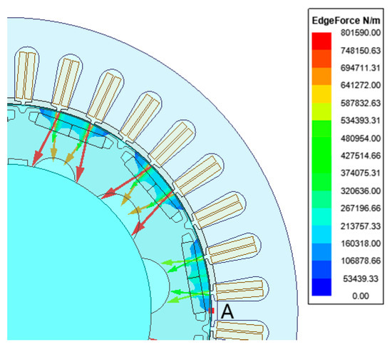
Figure 3.
Radial electromagnetic force density of stator teeth.
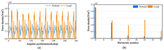
Figure 4.
Spatial waveform and order spectrum of radial electromagnetic force density: (a) radial electromagnetic force density; (b) harmonic components.
In Figure 4a, the radial electromagnetic force density has 12 peaks in the circumferential waveforms under no-load and rated load conditions. Figure 4b illustrates that the main spatial order of harmonics under no-load and load conditions are 0, 12, 24, 36, 48, , . The comparison between the spatial harmonic amplitudes of the radial electromagnetic force density in no-load conditions shows that the 24th, 36th, and 48th harmonic orders under rated load conditions significantly increase. From Equations (14) and (15), the interaction between armature-reaction fields and permanent magnet fields under rated load conditions increases the 24th, 36th, and 48th-order spatial harmonic components. In the non-zero spatial order, the radial electromagnetic force density amplitude of the 36th harmonic component is maximum in rated load conditions.
As shown in Table 2, the coupling effect of the 30th and 42nd order rotor tooth harmonics with the 6th order stator fundamental, and the coupling effect of the 6th order rotor fundamental with the −30th order stator tooth harmonics, lead to the 36th order electromagnetic force harmonics. As a result of the slot effect, there is a large radial electromagnetic force density amplitude.
When the motor speed is 4300 rpm, the fundamental frequency is . The waveform diagram of point A on the stator tooth in Figure 3 and its Fourier series decomposition at one cycle are shown in Figure 5. As can be seen, the same 12 peaks of electromagnetic force appear in the radial electromagnetic force density waveform in Figure 4a. The main harmonic frequencies of the radial electromagnetic force in Figure 4b are 860 Hz (12 ), 1720 Hz (24 ), 2580 Hz (36 ), 3440 Hz (48 )…
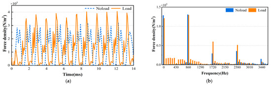
Figure 5.
Time waveform and amplitude spectrum of radial electromagnetic force density: (a) radial electromagnetic force density; (b) harmonic components.
The frequency component is significantly higher in rated load conditions than in no-load conditions due to the combined effect of the armature magnetic field and the permanent magnet magnetic field. Moreover, the amplitude of the harmonic component at a 0~12 low frequency is larger. The radial electromagnetic force density under load conditions at frequency 0 is slightly larger than that under no-load conditions because the fundamental amplitude of the air-gap flux density of the motor under load conditions is smaller than that in no-load conditions.
The temporal and spatial distributions of radial electromagnetic force density in the loaded condition are shown in Figure 6. The space–temporal order distribution of the radial electromagnetic force density is consistent with the theoretical analysis, and the space–temporal orders have mainly orders. Among the selected space orders (0 to 51) and temporal orders (0 to 36), there are seven more obvious orders in Figure 5, which can be expressed in the form of (space order, temporal order) as (0, 0), (0, 36), (12, 12), (24, 24), (36, 0), (36, 36), (48, 12).
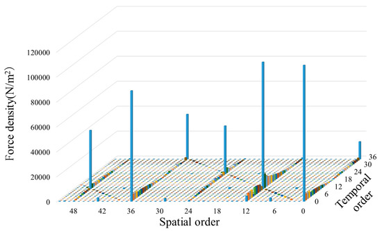
Figure 6.
Temporal and spatial order of radial electromagnetic force density under load.
The previous analysis depicts that the 36th order spatial harmonics are mainly influenced by the interaction between the stator-rotor tooth harmonics and the fundamental wave. In Table 2, (0, 36) is affected by the interaction between −30 order and 42 order stator tooth harmonics and 30 order and 42 order rotor magnetic field harmonics. Moreover, (12, 12) is affected by the fundamental wave of the 6th order armature magnetic field. Similarly, the radial electromagnetic force density amplitude corresponding to the other harmonic components results from the combined effect of the stator-rotor fundamental wave and the stator-rotor tooth harmonic field.
The previous study correctly provided the distribution rule of radial electromagnetic force density with the time and space position, laying the groundwork for the subsequent study of electromagnetic vibration characteristics of motors under multiple physical field coupling.
3.3. Modal and Vibration Response Analysis of PMSM
The stator frequency response is imported into the acoustic field for coupled magnetic-solid-acoustic field simulation and the stator housing acoustic analysis. In addition to the radial electromagnetic force as the excitation source, the motor structural mode affects its vibration. The stator, as the electromagnetic vibration source of the motor, has a complex physical structure due to the density of the winding coil and different materials. Considering the impact of the winding on the stator core mode and the stator shell on the overall mode, the three-dimensional (3D) finite element model of the stator core, winding, and shell can be established, as shown in Figure 7.
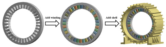
Figure 7.
Finite element model of stator core, winding and housing.
The stator core is made of laminated silicon steel sheet DW310_35 with a paint coating and the winding consists of copper wires filled with epoxy resin. Therefore, the stator core and winding materials should be calculated according to the composite material for its equivalent structural properties. The equivalent modulus of elasticity of the composite can be calculated using the Halpain–Tsai formula [18], i.e., Equation (17):
where is the interfacial shear modulus of the composite, which can generally be approximated by Equation (18):
where and are the elastic moduli for two materials; are the volume shares of the two materials in the composite; are their Poisson ratios. Using the core superposition coefficient of 0.95 in the study, the equivalent density of the stator core is 7458 , and its axial modulus of elasticity is calculated using Equations (17) and (18). Similarly, as shown in Table 4 and Table 5, the core and winding equivalent material parameters are obtained.
Table 4.
Equivalent properties of stator materials.
Table 5.
Radial modal frequencies of different core models.
The magnitude of the radial electromagnetic force in most motors is the same in the motor axial direction (Figure 8). Thus, the focus is on the consistent axial mode when analyzing the stator mode. By considering the influence of winding, the modal frequency of the stator core decreases as a whole because adding the winding has little effect on the overall stiffness and increases the overall mass. Simultaneously, adding the motor housing increases the overall stiffness and modal frequency. As can be seen, the structure with the winding and shell greatly influences the modal frequency of the stator.
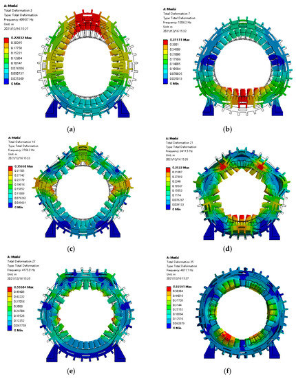
Figure 8.
Radial modal shapes of stator: (a) Model 2 f2 = 499.87 Hz; (b) Model 3 f3 = 1206.2 Hz; (c) Model 4 f4 = 2764.2 Hz; (d) Model 5 f5 = 3411.5 Hz; (e) Model 6 f6 = 4175.9 Hz; (f) Model 0 f0 = 4611.1 Hz.
4. Analysis and Discussion
The magnitude of the radial electromagnetic force in most motors is the same in the motor axial direction. Thus, the focus is on the consistent axial mode when analyzing the stator mode.
The equivalent radiated power level waterfall diagram of the stator surface vibration under the excitation of the electromagnetic force is shown in Figure 9 once the motor speed rises from 1300 rpm to 4300 rpm.
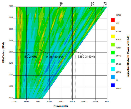
Figure 9.
Waterfall diagram of equivalent radiated power levels.
Figure 9 shows that the stator vibration intensity is relatively larger in the frequency range of 180–240 Hz, 1400–1500 Hz, and 3360–3440 Hz at most speeds. It can be seen from Figure 4b and Table 3 that besides the frequency harmonic of stator teeth, the other frequency harmonics also have radial electromagnetic forces that cannot be ignored. The second-order modal frequency of the stator structure is 204 Hz. Due to resonance bands, stator resonance occurs when the radial electromagnetic excitation frequency approaches the natural frequency. The 1400–1500 Hz frequency range falls in the resonance band of the stator’s third-order natural frequency of 1206 Hz. Moreover, the frequency range of 3360–3440 Hz falls in the stator’s 5th natural frequency 3411 Hz resonance band.
The results illustrate that the maximum vibration point in the frequency range of 1400–1500 Hz appears at 2500 rpm and 36th order frequency. Furthermore, the maximum vibration point in the 3360–3440 Hz frequency range occurs at 3400 rpm and 60th order frequency. The reason for this is that the 36th and 60th orders are orders, and the harmonics of these orders have a relatively large electromagnetic force amplitude, making it easy to produce a larger vibration response.
There are relatively larger vibration responses at 72 times the frequency at 2800 rpm, and 3400 rpm to 4000 rpm, and their frequencies are close to the modal frequency of the stator. Therefore, the harmonic in the radial electromagnetic force of the motor is more likely to produce a larger vibration response.
According to the stator electromagnetic vibration results, the radial electromagnetic force frequency is close to the stator’s natural frequency. Order 36 of electromagnetic force harmonics excite order 3 of stator resonance, and order 60 of electromagnetic force harmonics excite order 5 of stator resonance. Therefore, the resonance excitation does not necessarily require the force order to equal the modal order. Generally, the analysis of stator electromagnetic vibration is mainly concerned with the vibration generated by the non-zero minimum order harmonic of radial electromagnetic wave theory, before or after the spatial harmonic component of the radial electromagnetic force reaches a theoretical non-zero minimum spatial order.
When the frequency component is close to or equal to the frequency band of the stator radial mode, the electromagnetic force may induce large vibration in the stator even if the amplitude of the harmonic component of the excitation force wave is small. Figure 10 shows that the highest point of the equivalent radiation power level under the rated operating condition of 4300 rpm is 215 Hz, which is the resonance peak, and second-order resonance of the stator occurs. The second peak is 1648.3 Hz, the radial electromagnetic force density amplitude is near 1720 Hz, which is large, and the frequency is close to the stator fourth-order modal frequency of 1659 Hz. Thus, the fourth-order resonance also occurs. Then, the radiation power is large at 2221.7 Hz, near stator 4th mode frequency 2241 Hz, and the resonance peak. At 2580 Hz, 5160 Hz, and other frequency doubling places, it is relatively far from the modal frequency of 2241 Hz, but also in the resonance band, and its electromagnetic force amplitude is large.
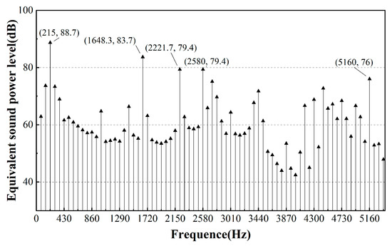
Figure 10.
Equivalent radiation power level diagrams at 4300 rpm.
The motor has multiple vibration peaks in operation. As the excitation frequency of electromagnetic force is close to the stator structure’s natural frequency, the spatial order of large electromagnetic force amplitude at this frequency is not equal to the modal order corresponding to the stator structure’s natural frequency. Hence, the resonance response is not significant. Figure 11 depicts that the vibration and noise of the sound field mainly diffuse from the motor shell to the surroundings, and the sound pressure decreases when the distance increases. The maximum A-weighted sound pressure at 1 m from the motor is about 80 dB(A).
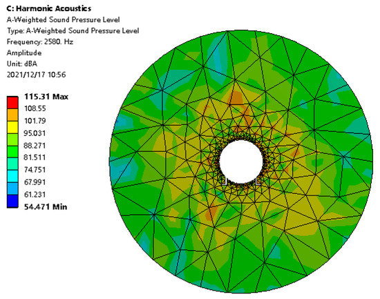
Figure 11.
A weighted sound pressure level cloud chart at 4300 rpm.
5. Experimental Verification
The results of the theoretical analysis compared with the experimental data in [19,20] are shown in Table 6. The vibration experiments were conducted on the CWSPM-12s10p motor under variable speed conditions with constant-load torque, and 3D waterfall plots of motor sound pressure levels versus motor speed and frequency were obtained. In the experiment, the input variables were the operational speed, the operational torque, the dc bus voltage, and the modulation strategy. The experimental results show that the motor produces larger vibration noise at the order of 10, 20, 30, …, 2np, and at the frequency of mode 2, due to resonance [19]. The experimental results are in agreement with the presented theoretical analysis.
Table 6.
Comparison of the results of theoretical analysis and experiments.
The experiments were carried out on a 4-pole, 6-slot PMSM with a constant output torque of 8 N.m, and a 3D waterfall plot of stator sound pressure level (SPL) versus motor speed and frequency under load was obtained. The experimental results show that the motor has a larger vibration noise in the frequency range of 1900~2400 Hz, which corresponds to the stator’s second-order natural frequency resonance band. Therefore, the electromagnetic force wave of the eight-pole motor has a larger amplitude in the spatial order harmonics of . During the speeding up of the motor, larger vibrations and noise are generated in the order of 4, 8, 12 ..., 4 n, and the second-order resonance is generated in the order of 40, 48 [20]. The experimental results are also consistent with the theoretical conclusions.
6. Conclusions
The electromagnetic vibration characteristics of the internal PMSM based on multi-physics coupled fields were comprehensively studied in this paper, and the main conclusions are as follows:
The influential factors in the spatial order and temporal frequency of air-gap flux density and the electromagnetic force wave of the interior PMSM are motor pole number , the number of stator slots , harmonic frequency of rotor , harmonic frequency of armature field , and harmonic frequency of armature field . For the integer-slot interior PMSM, the spatial order of the electromagnetic force wave and the temporal frequency is mainly and , respectively.
The stator structure mode is affected by the winding and the structure of the stator shell. When the excitation frequency of radial air-gap electromagnetic force is close to the stator natural frequency band, even if the order of the electromagnetic force harmonic space is not equal to the order corresponding to the stator mode, electromagnetic force may also induce larger vibration in the stator structure.
The frequency component is near or equal to the stator radial modal frequency in the spatial harmonic component of radial electromagnetic force before or after the theoretical non-zero minimum spatial order. Even if the excitation electromagnetic wave harmonic component amplitude is smaller, electromagnetic force may also induce larger vibration intensity in the stator.
Author Contributions
Conceptualization, W.Y.; methodology, K.J.; software, D.W.; formal analysis, J.Y. and Y.F. All authors have read and agreed to the published version of the manuscript.
Funding
This research is supported by the National Natural Science Foundation of China (Grant No. 52272361).
Conflicts of Interest
The authors declare that they have no known competing financial interests or personal relationships that could have appeared to influence the work reported in this paper.
References
- Liu, C.; Chau, K.T.; Lee, C.H.T.; Song, Z. A Critical Review of Advanced Electric Machines and Control Strategies for Electric Vehicles. Proc. IEEE 2021, 109, 1004–1028. [Google Scholar] [CrossRef]
- Yang, Z.; Shang, F.; Brown, I.P.; Krishnamurthy, M. Comparative study of interior permanent magnet, induction, and switched reluctance motor drives for EV and HEV applications. IEEE Trans. Transp. Electr. 2015, 1, 245–254. [Google Scholar] [CrossRef]
- Saponara, S.; Lee, C.H.T.; Wang, N.X.; Kirtley, J.L. Electric Drives and Power Chargers: Recent Solutions to Improve Performance and Energy Efficiency for Hybrid and Fully Electric Vehicles. IEEE Veh. Technol. Mag. 2020, 15, 73–83. [Google Scholar] [CrossRef]
- Lu, Y.; Li, J.; Qu, R.; Ye, D.; Lu, H.; Sun, J.; Ge, M.; Xu, H. Electromagnetic Force and Vibration Analysis of Permanent-Magnet-Assisted Synchronous Reluctance Machines. IEEE Trans. Ind. Appl. 2018, 54, 4246–4256. [Google Scholar] [CrossRef]
- Xing, Z.; Zhao, W.; Wang, X.; Sun, Y. Reduction of Radial Electromagnetic Force Waves Based on PM Segmentation in SPMSMs. IEEE Trans. Magn. 2020, 56, 1–7. [Google Scholar] [CrossRef]
- Wang, X.; Sun, X.; Gao, P. Study on the effects of rotor-step skewing on the vibration and noise of a PMSM for electric vehicles. IET Electr. Power Appl. 2020, 14, 131–138. [Google Scholar] [CrossRef]
- Chen, Y.; Zhu, Z.; Howe, D. Vibration of Permanent Magnet Brushless Machines Having a Fractional Number of Slots per Pole; Institute of Electrical and Electronics Engineers Computer Society: San Diego, CA, USA, 2006; p. 496. [Google Scholar]
- Islam, R.; Husain, I. Analytical model for predicting noise and vibration in permanent-magnet synchronous motors. IEEE Trans. Ind. Appl. 2010, 46, 2346–2354. [Google Scholar] [CrossRef]
- Fang, Y.; Zhang, T. Vibroacoustic characterization of a permanent magnet synchronous motor powertrain for electric vehicles. IEEE Trans. Energy Conver. 2018, 33, 272–280. [Google Scholar] [CrossRef]
- Wu, S.; Zuo, S.; Wu, X.; Lin, F.; Zhong, H.; Zhang, Y. Vibroacoustic Prediction and Mechanism Analysis of Claw Pole Alternators. IEEE Trans. Ind. Electron. 2017, 64, 4463–4473. [Google Scholar] [CrossRef]
- Yang, H.; Chen, Y. Influence of radial force harmonics with low mode number on electromagnetic vibration of PMSM. IEEE Trans. Energy Conver. 2014, 29, 38–45. [Google Scholar] [CrossRef]
- Zhu, Z.Q.; Xia, Z.P.; Wu, L.J.; Jewell, G.W. Analytical modeling and finite-element computation of radial vibration force in fractional-slot permanent-magnet brushless machines. IEEE Trans. Ind. Appl. 2010, 46, 1908–1918. [Google Scholar] [CrossRef]
- Yang, Z.; Wang, S.; Hong, J.; Li, J. Analysis of electromagnetic exciting force and vibration of rotating armature permanent magnet synchronous motor. J. Eng. 2018, 2018, 1903–1908. [Google Scholar] [CrossRef]
- Verez, G.; Barakat, G.; Amara, Y.; Hoblos, G. Impact of pole and slot combination on vibrations and noise of electromagnetic origins in permanent magnet synchronous motors. IEEE Trans. Magn. 2015, 51, 1–4. [Google Scholar] [CrossRef]
- Lin, F.; Zuo, S.; Deng, W.; Wu, S. Noise Prediction and Sound Quality Analysis of Variable-Speed Permanent Magnet Synchronous Motor. IEEE Trans. Energy Conver. 2017, 32, 698–706. [Google Scholar] [CrossRef]
- Wu, S.; Tong, W.; Li, W.; Yu, S.; Tang, R. Electromagnetic Vibration Analysis of High-Speed Permanent Magnet Synchronous Machines with Amorphous Metal Stator Cores Considering Current Harmonics. IEEE Trans. Ind. Electron. 2020, 67, 10156–10167. [Google Scholar] [CrossRef]
- Lan, H. Research on Electromagnetic Force Waves and Electromagnetic Vibration of PMSMs. Ph.D. Thesis, Harbin Institute of Technology, Harbin, China, 2019. [Google Scholar]
- Zhang, J.; Yang, H.; Li, X.; Ye, W. A method of reducing motor vibration: Natural frequency, damping ratio, and vibration analysis of CFRP motor frame. Shock Vib. 2020, 2020, 6021640. [Google Scholar] [CrossRef]
- Fakam, M.; Hecquet, M.; Lanfranchi, V.; Randria, A. Design and magnetic noise reduction of the surface permanent magnet synchronous machine using complex air-gap permeance. IEEE Trans. Magn. 2015, 51, 1–9. [Google Scholar] [CrossRef]
- Lee, S.H.; Hong, J.P.; Hwang, S.M.; Lee, W.T.; Lee, J.Y.; Kim, Y.K. Optimal Design for Noise Reduction in Interior Permanent-Magnet Motor. IEEE Trans. Ind. Appl. 2009, 45, 1954–1960. [Google Scholar]


Disclaimer/Publisher’s Note: The statements, opinions and data contained in all publications are solely those of the individual author(s) and contributor(s) and not of MDPI and/or the editor(s). MDPI and/or the editor(s) disclaim responsibility for any injury to people or property resulting from any ideas, methods, instructions or products referred to in the content. |
© 2023 by the authors. Licensee MDPI, Basel, Switzerland. This article is an open access article distributed under the terms and conditions of the Creative Commons Attribution (CC BY) license (https://creativecommons.org/licenses/by/4.0/).